Embed Size (px)
Citation preview
The Journal of Implant & Advanced Clinical Dentistry
Volume 10, No. 1 JaNuary 2018
Palatal Torus Removal
Stereolithographic Modeling
Palatal Torus Removal
Stereolithographic Modeling

The Best Things in Life Are FREE!
Subscribe now to enjoy articles free of charge that will benefit you, the actively practicing dental provider. With each JIACD issue, readers are afforded the opportunity to
assess clinical techniques, cases, literature reviews, and expert commentary that can immediately impact their daily dental practice.
Email notification when new issues are available online.
Start your FREE subscription today at www.jiacd.com
The Journal of Implant & Advanced Clinical Dentistry
Volume 8, No. 8 December 2016
Full Mouth Rehabilitation of Periodontitis Patient
Implant-Supported Milled Bar
Overdenture
The Journal of Implant & Advanced Clinical Dentistry
Volume 8, No. 1 march 2016
Treatment of the Atrophic Maxilla with Autogenous Blocks
Modified Mandibular Implant Bar Overdenture
The Journal of Implant & Advanced Clinical Dentistry
Volume 8, No. 3 may/JuNe 2016
Treatment of Mandibular Central Giant Cell Granuloma
Titanium Mesh Ridge Augmentation for Dental
Implant Placement
The Journal of Implant & Advanced Clinical Dentistry
Volume 8, No. 4 July/August 2016
Mandibular Overdentures with Mini-Implants
Augmentation of Severe Ridge Defect with rhBMP-2
and Titanium Mesh
The Journal of Implant & Advanced Clinical DentistryVolume 10, No. 1 • JaNuary 2018
Table of Contents
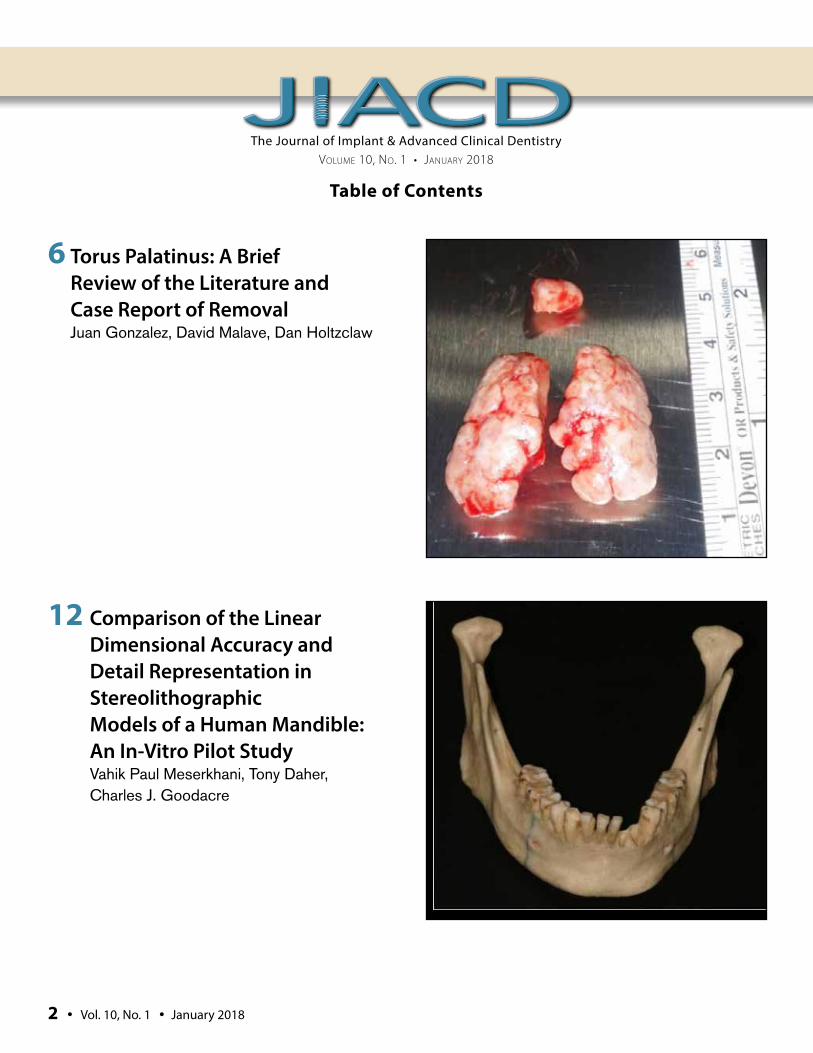
6 Torus Palatinus: A Brief Review of the Literature and Case Report of Removal Juan Gonzalez, David Malave, Dan Holtzclaw
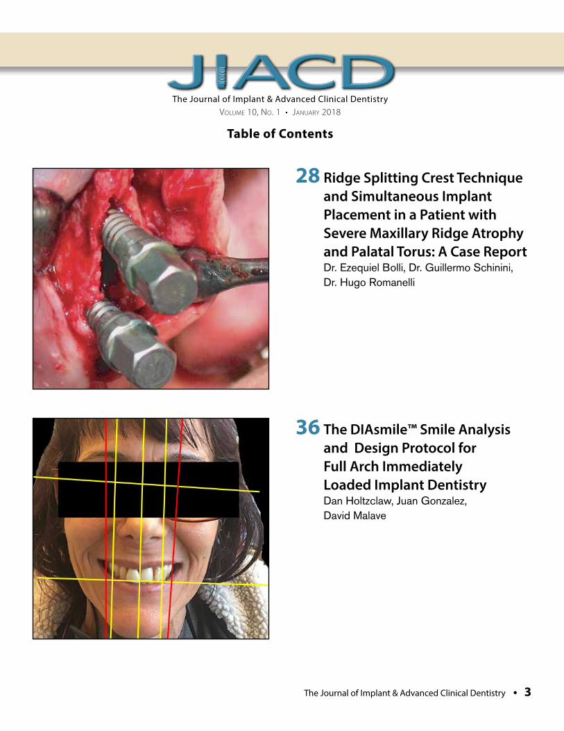
12 Comparison of the Linear Dimensional Accuracy and Detail Representation in Stereolithographic Models of a Human Mandible: An In-Vitro Pilot Study Vahik Paul Meserkhani, Tony Daher, Charles J. Goodacre
2 • Vol. 10, No. 1 • January 2018
The Journal of Implant & Advanced Clinical Dentistry • 3
The Journal of Implant & Advanced Clinical DentistryVolume 10, No. 1 • JaNuary 2018
Table of Contents
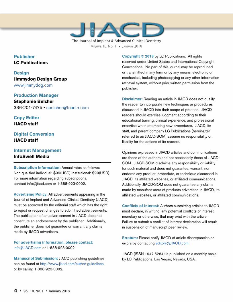
28 Ridge Splitting Crest Technique and Simultaneous Implant Placement in a Patient with Severe Maxillary Ridge Atrophy and Palatal Torus: A Case Report Dr. Ezequiel Bolli, Dr. Guillermo Schinini, Dr. Hugo Romanelli
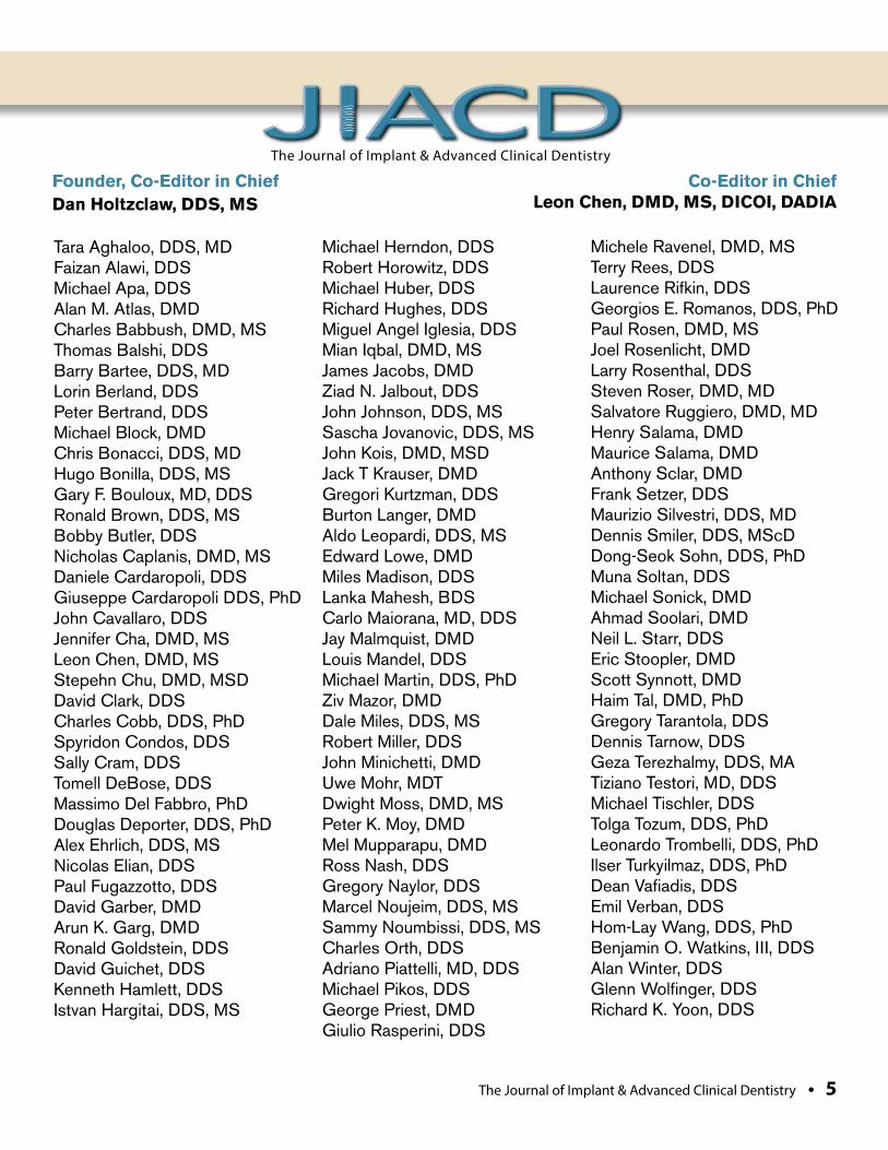
36 The DIAsmile™ Smile Analysis and Design Protocol for Full Arch Immediately Loaded Implant Dentistry Dan Holtzclaw, Juan Gonzalez, David Malave
The Journal of Implant & Advanced Clinical DentistryVolume 10, No. 1 • JaNuary 2018
PublisherLC Publications
DesignJimmydog Design Group www.jimmydog.com
Production ManagerStephanie Belcher 336-201-7475 • [email protected]
Copy EditorJIACD staff
Digital ConversionJIACD staff
Internet ManagementInfoSwell Media
Subscription Information: Annual rates as follows: Non-qualified individual: $99(USD) Institutional: $99(USD). For more information regarding subscriptions, contact [email protected] or 1-888-923-0002.
Advertising Policy: All advertisements appearing in the Journal of Implant and Advanced Clinical Dentistry (JIACD) must be approved by the editorial staff which has the right to reject or request changes to submitted advertisements. The publication of an advertisement in JIACD does not constitute an endorsement by the publisher. Additionally, the publisher does not guarantee or warrant any claims made by JIACD advertisers.
For advertising information, please contact:[email protected] or 1-888-923-0002
Manuscript Submission: JIACD publishing guidelines can be found at http://www.jiacd.com/author-guidelines or by calling 1-888-923-0002.
Copyright © 2018 by LC Publications. All rights reserved under United States and International Copyright Conventions. No part of this journal may be reproduced or transmitted in any form or by any means, electronic or mechanical, including photocopying or any other information retrieval system, without prior written permission from the publisher.
Disclaimer: Reading an article in JIACD does not qualify the reader to incorporate new techniques or procedures discussed in JIACD into their scope of practice. JIACD readers should exercise judgment according to their educational training, clinical experience, and professional expertise when attempting new procedures. JIACD, its staff, and parent company LC Publications (hereinafter referred to as JIACD-SOM) assume no responsibility or liability for the actions of its readers.
Opinions expressed in JIACD articles and communications are those of the authors and not necessarily those of JIACD-SOM. JIACD-SOM disclaims any responsibility or liability for such material and does not guarantee, warrant, nor endorse any product, procedure, or technique discussed in JIACD, its affiliated websites, or affiliated communications. Additionally, JIACD-SOM does not guarantee any claims made by manufact-urers of products advertised in JIACD, its affiliated websites, or affiliated communications.
Conflicts of Interest: Authors submitting articles to JIACD must declare, in writing, any potential conflicts of interest, monetary or otherwise, that may exist with the article. Failure to submit a conflict of interest declaration will result in suspension of manuscript peer review.
Erratum: Please notify JIACD of article discrepancies or errors by contacting [email protected]
JIACD (ISSN 1947-5284) is published on a monthly basis by LC Publications, Las Vegas, Nevada, USA.
4 • Vol. 10, No. 1 • January 2018
The Journal of Implant & Advanced Clinical Dentistry • 5
Tara Aghaloo, DDS, MDFaizan Alawi, DDSMichael Apa, DDSAlan M. Atlas, DMDCharles Babbush, DMD, MSThomas Balshi, DDSBarry Bartee, DDS, MDLorin Berland, DDSPeter Bertrand, DDSMichael Block, DMDChris Bonacci, DDS, MDHugo Bonilla, DDS, MSGary F. Bouloux, MD, DDSRonald Brown, DDS, MSBobby Butler, DDSNicholas Caplanis, DMD, MSDaniele Cardaropoli, DDSGiuseppe Cardaropoli DDS, PhDJohn Cavallaro, DDSJennifer Cha, DMD, MSLeon Chen, DMD, MSStepehn Chu, DMD, MSD David Clark, DDSCharles Cobb, DDS, PhDSpyridon Condos, DDSSally Cram, DDSTomell DeBose, DDSMassimo Del Fabbro, PhDDouglas Deporter, DDS, PhDAlex Ehrlich, DDS, MSNicolas Elian, DDSPaul Fugazzotto, DDSDavid Garber, DMDArun K. Garg, DMDRonald Goldstein, DDSDavid Guichet, DDSKenneth Hamlett, DDSIstvan Hargitai, DDS, MS
Michael Herndon, DDSRobert Horowitz, DDSMichael Huber, DDSRichard Hughes, DDSMiguel Angel Iglesia, DDSMian Iqbal, DMD, MSJames Jacobs, DMDZiad N. Jalbout, DDSJohn Johnson, DDS, MSSascha Jovanovic, DDS, MSJohn Kois, DMD, MSDJack T Krauser, DMDGregori Kurtzman, DDSBurton Langer, DMDAldo Leopardi, DDS, MSEdward Lowe, DMDMiles Madison, DDSLanka Mahesh, BDSCarlo Maiorana, MD, DDSJay Malmquist, DMDLouis Mandel, DDSMichael Martin, DDS, PhDZiv Mazor, DMDDale Miles, DDS, MSRobert Miller, DDSJohn Minichetti, DMDUwe Mohr, MDTDwight Moss, DMD, MSPeter K. Moy, DMDMel Mupparapu, DMDRoss Nash, DDSGregory Naylor, DDSMarcel Noujeim, DDS, MSSammy Noumbissi, DDS, MSCharles Orth, DDSAdriano Piattelli, MD, DDSMichael Pikos, DDSGeorge Priest, DMDGiulio Rasperini, DDS
Michele Ravenel, DMD, MSTerry Rees, DDSLaurence Rifkin, DDSGeorgios E. Romanos, DDS, PhDPaul Rosen, DMD, MSJoel Rosenlicht, DMDLarry Rosenthal, DDSSteven Roser, DMD, MDSalvatore Ruggiero, DMD, MDHenry Salama, DMDMaurice Salama, DMDAnthony Sclar, DMDFrank Setzer, DDSMaurizio Silvestri, DDS, MDDennis Smiler, DDS, MScDDong-Seok Sohn, DDS, PhDMuna Soltan, DDSMichael Sonick, DMDAhmad Soolari, DMDNeil L. Starr, DDSEric Stoopler, DMDScott Synnott, DMDHaim Tal, DMD, PhDGregory Tarantola, DDSDennis Tarnow, DDSGeza Terezhalmy, DDS, MATiziano Testori, MD, DDSMichael Tischler, DDSTolga Tozum, DDS, PhDLeonardo Trombelli, DDS, PhDIlser Turkyilmaz, DDS, PhDDean Vafiadis, DDSEmil Verban, DDSHom-Lay Wang, DDS, PhDBenjamin O. Watkins, III, DDSAlan Winter, DDSGlenn Wolfinger, DDSRichard K. Yoon, DDS
Founder, Co-Editor in ChiefDan Holtzclaw, DDS, MS
Co-Editor in ChiefLeon Chen, DMD, MS, DICOI, DADIA
The Journal of Implant & Advanced Clinical Dentistry
Gonzalez et al
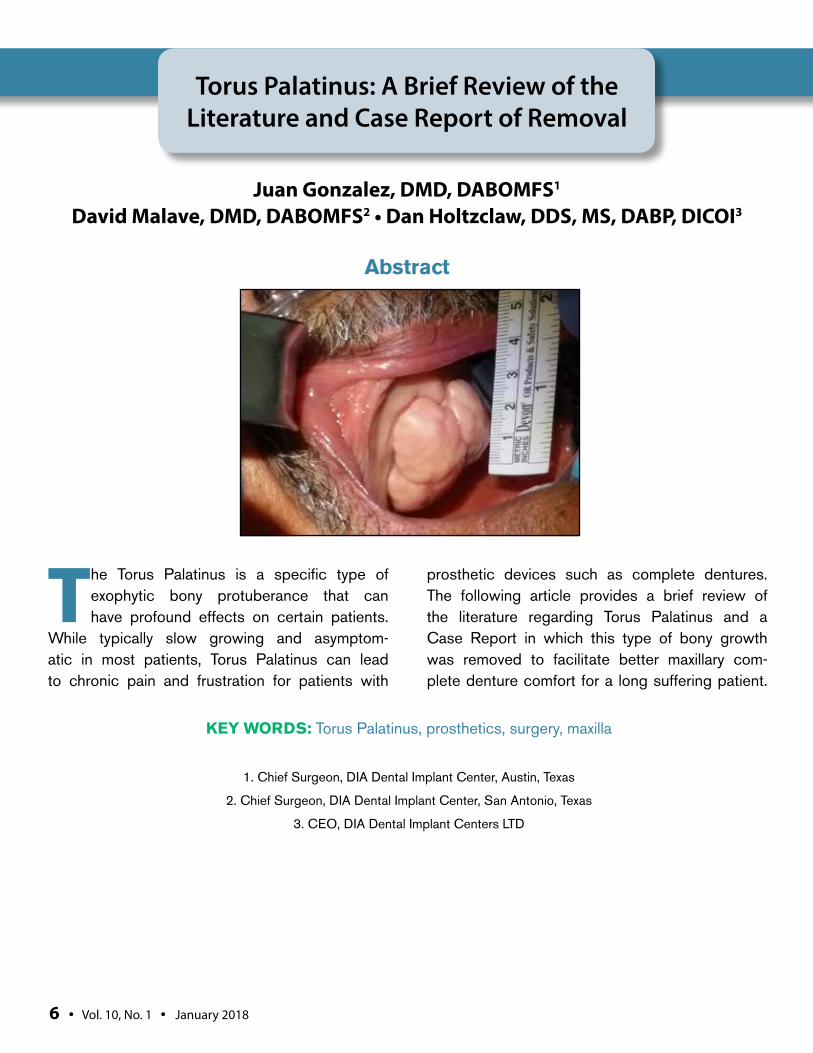
The Torus Palatinus is a specific type of exophytic bony protuberance that can have profound effects on certain patients.
While typically slow growing and asymptom-atic in most patients, Torus Palatinus can lead to chronic pain and frustration for patients with
prosthetic devices such as complete dentures. The following article provides a brief review of the literature regarding Torus Palatinus and a Case Report in which this type of bony growth was removed to facilitate better maxillary com-plete denture comfort for a long suffering patient.
Torus Palatinus: A Brief Review of the Literature and Case Report of Removal
Juan Gonzalez, DMD, DABOMFS1 David Malave, DMD, DABOMFS2 • Dan Holtzclaw, DDS, MS, DABP, DICOI3
1. Chief Surgeon, DIA Dental Implant Center, Austin, Texas
2. Chief Surgeon, DIA Dental Implant Center, San Antonio, Texas
3. CEO, DIA Dental Implant Centers LTD
Abstract
KEY WORDS: Torus Palatinus, prosthetics, surgery, maxilla
6 • Vol. 10, No. 1 • January 2018
Gonzalez et al
The Journal of Implant & Advanced Clinical Dentistry • 7
Gonzalez et al
BACKGROUNDIn general, tori are benign bony protuberances composed of dense cortical bone and covered with a friable and poorly vascularized mucosa.1,2 The Torus Palatinus (TP), specifically, most com-monly occurs at the palatal midline at the union of the palatine apophysis of the maxillae.3 Etiol-ogy of TP are poorly understood and a number of reasons for their development have been sug-gested. Genetics is a widely postulated theory for the development of TP4-7 as these bony pro-tuberances have shown higher prevalence in certain ethnic population groups.5-12 Although findings of elevated TP prevalence in certain populations have been noted, little consistency has been found amongst these studies and, as such, genetics has been unable to be confirmed as a firm etiology. Another suggestion for the development of TP is an association with brux-ism or heavy occlusal forces as these have also been somewhat linked to the etiology of mandib-ular tori.13,14 This etiology, specifically in relation to TP, has been questioned as several studies have shown that the prevalence of TP may not necessarily correspond with parafunctional hab-its14,15 or dentate status.8 Other suggested causes of TP include trauma, vitamin deficien-cies, diet, and use of certain medications.16-19
A number of studies have reported on the prevalence of TP in various populations. Son-nier et al.8 found a 22.8% prevalence of TP in Caucasian North Americans and 12.2% preva-lence in African American – North Americans. Studies of Norwegian populations found preva-lence of TP to be 9.22-36.1%9,10 while studies of Thais found TP prevalence of 23.1-58%.6,11 In a study of Israeli Jews, Gorsky et al.12 found TP prevalence of 21% while a study of Saudi
Arabians found prevalence of only 7.79%20 and a study of Germans found TP preva-lence of 13.5%.11 Concerning sex, most stud-ies have shown a higher prevalence of TP in females.4-12 A recent study by al Zarea et al.,20
however, noted that men had higher prevalence of TP. Concerning age, the onset of TP seems to occur earlier in life compared to other types of oral exophytic bony protuberances such as mandibular tori.5,11 However, due to their slow and asymptomatic growth, TP are not commonly noted until the third to sixth decades of life.7,9-11 Concerning size, TP tend to be larger than other oral bony protuberances.8 While most TP tend to be classified as “small” (less than 2mm)9,11,18 some studies have shown TP to reach average sizes exceeding 20mm in length.5,8 Concerning shape, TP have been classified as flat, spindle shaped, nodular, and lobular.5,11,18,21 Very little consistency, however, has been found amongst studies concerning the shape of TP. In general, most TP are asymptomatic although exception-ally large TP interfere with speech, create food traps, or ulcerate/lacerate during mastication of particular foods.3,8,20,21 The most common prob-lem associated with TP is prosthetic interfer-ence leading to prosthetic instability.20 These prosthetic issues, particularly in the case of complete maxillary dentures, is the most fre-quent impetus for TP removal.3,8 In the pres-ent Case Report, surgical removal of a large TP is described for this reason in particular.
CASE REPORTAn 80 year old male with an unremarkable med-ical history presented with a chief complaint of being unable to comfortably wear his upper denture due to “the large bump on the roof of
8 • Vol. 10, No. 1 • January 2018
my mouth.” The patient noted that the “bump” had been present for as long as he could remember and had not changed in size as far as he could tell. Furthermore, the patient stated that the bump was asymptomatic other than causing interference with being able to wear an upper denture. Intraoral examination revealed
an edentulous maxilla with a large, non-mobile, lobular, exophytic protuberance of the mid-max-illa (Figure 1). Cone beam computed tomog-raphy (CBCT) scanning suggested the growth to be dense, radiopaque bone. The growth in question had characteristics consistent with a Torus Palatinus and measured approximately
Figure 1: Pre-surgical examination showing extremely large Torus Palatinus that is interfering with the patient’s maxillary complete denture.
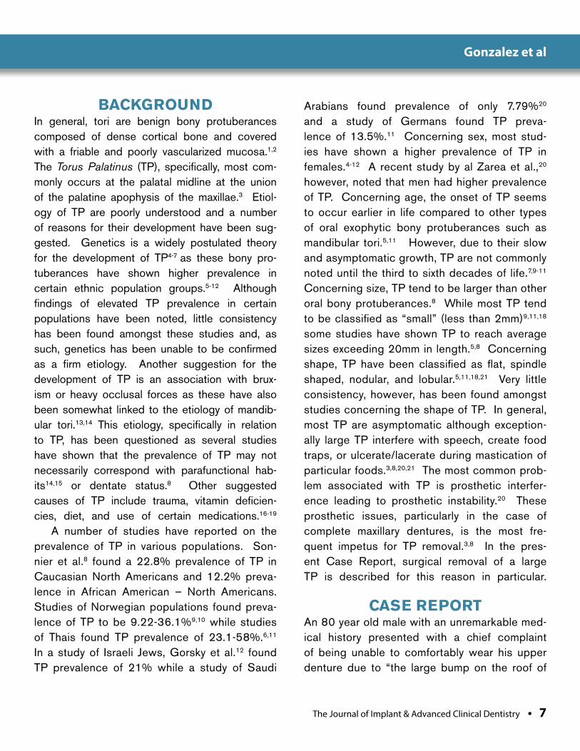
Figure 2: Excised Torus Palatinus following sectioning with a surgical high speed hand piece and mallet/chisel removal.
Gonzalez et al
The Journal of Implant & Advanced Clinical Dentistry • 9
30x35mm in size. The patient was informed of the diagnosis of Torus Palatinus and sur-gical removal was recommended to facilitate better fit of a complete maxillary denture. The patient was consented for treatment and a com-plete history and physical was performed. With findings of an unremarkable medical history,
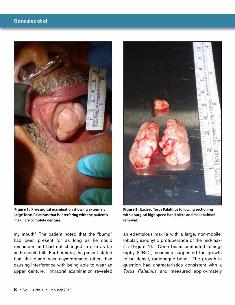
the patient was prepped for surgery with intra-venous and local anesthesia. A full thickness palatal flap was accomplished with an incision lateral to one side of the TP for exposure of the bony growth. The TP was sectioned in half with a surgical high speed hand piece and removed from the palate with a mallet and sharp chisel (Figure 2). The palate was carefully evaluated for any remaining sharp bony ledges which were subsequently removed and the surgical site was copiously irrigated with sterile saline. Closure was achieved with 4-0 chromic gut sutures (Figure 3). Post-operative pain medica-tion and antibiotics were provided to the patient in the usual fashion. Healing was unevent-ful and the patient had his maxillary complete denture remade to accommodate the healed palate. The patient reported a dramatically improved fit of his new maxillary denture and no longer reported any discomfort with its use.
CONCLUSION Although not a pathologically worrisome entity, the Torus Palatinus is a commonly seen condition that can negatively affect cer-tain patients. The removal of TP is a relatively simple procedure for surgically trained den-tal providers and can significantly improve the quality of life for many patients, espe-cially those with maxillary prosthetics. l
Figure 3: Sutured palate following removal of Torus Palatinus. Notice the immediate and dramatic change in palatal anatomy following the surgical procedure.
Correspondence:Dr. Juan GonzalezDIA Dental Implant Center11515 Toepperwein RoadSuite 102Live Oak, Texas 78233
Gonzalez et al

10 • Vol. 10, No. 1 • January 2018
DisclosureThe authors report no conflicts of interest with anything mentioned in this article.
References1. Goldman M, Denduluri N, Berman A. A novel case of bisphosphonate related
osteonecrosis of the torus palatinus in a patient with metastatic breast cancer. Oncology 2006;71:306-308.
2. Cawson R, Odell E – editors. Cawson’s essentials of oral pathology and oral medicine. London: Churchill Livingstone;2008.
3. García-García AS, Martínez-González JM, Gómez-Font R, Soto-Rivadeneira A, Oviedo-Roldán L. Current status of the torus palatinus and torus mandibularis. Med Oral Patol Oral Cir Bucal. 2010 Mar 1;15(2):e353-60.
4. Gorsky M, Bukai A, Shohat M. Genetic influence on the prevalence of torus palatinus. Am J Med Genet. 1998 Jan 13;75(2):138-40.
5. Al-Bayaty HF, Murti PR, Matthews R, Gupta PC. An epidemiological study of tori among 667 dental outpatients in Trinidad & Tobago, West Indies. Int Dent J. 2001 Aug;51(4):300-4.
6. Sirirungrojying S, Kerdpon D. Relationship between oral tori and temporomandibular disorders. Int Dent J. 1999 Apr;49(2):101-4.
7. Bruce I, Ndanu TA, Addo ME. Epidemiological aspects of oral tori in a Ghanaian community.. Int Dent J. 2004 Apr;54(2):78-82.
8. Sonnier KE, Horning GM, Cohen ME. Palatal tubercles, palatal tori, and mandibular tori: prevalence and anatomical features in a U.S. population. J Periodontol. 1999 Mar;70(3):329-36.
9. Eggen S, Natvig B. Concurrence of torus mandibularis and torus palatinus. Scand J Dent Res. 1994 Feb;102(1):60-3.
10. Haugen LK.Palatine and mandibular tori. A morphologic study in the current Norwegian population. Acta Odontol Scand. 1992 Apr;50(2):65-77.
11. Reichart PA, Neuhaus F, Sookasem M. Prevalence of torus palatinus and torus mandibularis in Germans and Thai. Community Dent Oral Epidemiol. 1988 Feb;16(1):61-4.
12. Gorsky M, Raviv M, Kfir E, Moskona D. Prevalence of torus palatinus in a population of young and adult Israelis. Arch Oral Biol. 1996 Jun;41(6):623-5
13. Jeong CW, Kim KH, Jang HW, Kim HS, Huh JK. The relationship between oral tori and bite force. Cranio. 2018 Jan 12:1-8.
14. Yoshinaka M, Ikebe K, Furuya-Yoshinaka M, Maeda Y. Prevalence of torus mandibularis among a group of elderly Japanese and its relationship with occlusal force. Gerodontology. 2014 Jun;31(2):117-22.
15. Yoshinaka M, Ikebe K, Furuya-Yoshinaka M, Hazeyama T, Maeda Y. Prevalence of torus palatinus among a group of Japanese elderly. J Oral Rehabil. 2010 Nov;37(11):848-53.
16. Morrison MD, Tamimi F. Oral tori are associated with local mechanical and systemic factors: a case-control study. J Oral Maxillofac Surg. 2013 Jan;71(1):14-22.
17. Khan S, Shah SAH, Ali F, Rasheed D. Concurrence of Torus Palatinus, Torus Mandibularis and Buccal Exostosis. J Coll Physicians Surg Pak. 2016 Nov;26(11):111-113.
18. Eggen S, Natvig B, Gåsemyr J. Variation in torus palatinus prevalence in Norway. Scand J Dent Res. 1994 Feb;102(1):54-9.
19. Sasaki H, Ikedo D, Kataoka M, Kido J, Kitamura S, Nagata T. Pronounced palatal and mandibular tori observed in a patient with chronic phenytoin therapy: a case report. J Periodontol. 1999 Apr;70(4):445-8.
20. Al Zarea BK. Prevalence and pattern of torus palatinus and torus mandibularis among edentulous patients of Saudi Arabia. Clin Interv Aging. 2016 Feb 24;11:209-13.
21. El Achkar VN, Lopes SL, Pinto AS, do Prado RF, Kaminagakura E. Imaging Aspects of Palatal Torus in Cone Beam Computed Tomography and Magnetic Resonance: Case Report. Acta Stomatol Croat. 2016 Dec;50(4):359-364.
ATTENTION PROSPECTIVE
AUTHORSJIACD wants
to publish your article!
The Journal of Implant & Advanced Clinical Dentistry
For complete details regarding publication in
JIACD, please refer to our author guidelines
at the following link: jiacd.com/
author-guidelines or email us at:
Gonzalez et al
The Journal of Implant & Advanced Clinical Dentistry • XX
Gonzalez et al
The Journal of Implant and Advanced Clinical Dentistry has been providing high quality, peer reviewed dental journals since 2007. We take pride in knowing that tens of thousands of readers around the world continue to read and contribute articles to JIACD. As you can imagine, there is a lot of expense involved in managing a top quality dental journal and we sincerely appreciate our advertisers purchasing ad space in both the journal and on the website which allows our monthly journals to continue to be free to all of our readers. In an e�ort to streamline our business practice and continue to provide no-fee, open access journals, JIACD is now sponsored exclusively by Osseofuse International Inc., a cutting edge dental implant company that provides exceptional implants and prosthetics and believes in the free distribution of information towards clinical advancements to dentists in the U.S. and around the world.
This generous sponsorship, which provides funding towards our operating expenses, allows JIACD to focus on the more important aspects of our journal; monthly publishing of relevant clinical practices.
As a reader or author of JIACD, nothing will change. In fact, readers will see less advertisements overall and authors can continue to submit articles relating to any clinical topic. We here at JIACD sincerely appreciate the continued �nancial support by Osseofuse International Inc., and are excited about the opportunity it a�ords. Thank you once again for your generous support.
Sincerely,
Leon Chen MD, MS, Co-Editor-in-Chief | Dave Beller, Director |The JIACD Team
International Inc.
Meserkhani et al
Statement of Problem: The accu-racy of stereolithographic models pro-duced by commercial biomedical laboratories using cone beam computed tomog-raphy (CBCT) data has not been investigated.
Purpose: The purpose of this study was to determine the accuracy of stereolithographic models of a human mandible produced by three commercial biomedical laboratories using data acquired from cone-beam technology. Materials and Methods: One adult dry human mandible served as the reference object, and was cut into three segments. Reference notches were placed in each segment to permit measurement and comparisons of linear dimensional accuracy and height of contour at 10 different sites. The sections were imaged using cone-beam tech-nology. The acquired data were sent to three different medical modeling laboratories to pro-duce one stereolithographic model for each seg-ment. These models were then measured using the reference notches and the data were ana-lyzed using an analysis of variance ANOVA and the LSD test at the significance level of α=0.05.
Results: Comparison of the linear measure-ments of the original human specimen and the
three stereolithographic models at the 10 dif-ferent sites at, revealed statistically significant differences when the reference notches were used for measurements at all 10 measurement points due to the poor surface detail repro-duction of all the models. However, when the heights of contour of the same sites were used 6 out of ten sites with Protomed Laboratory, 4 out of ten sites with Biomedical Modeling labo-ratory and 3 out of ten sites with Medical mod-eling laboratory had no significant differences. Conclusion: All three laboratories models exhibited significant differences when the mea-surement were at the reference notches, only thirteen out of 30 sites had no significant dif-ferences when height of contour were used for measurements. The result of this study indi-cates adequate dimensional accuracy and lack of surface details of stereolithographic models produced by different commercial laboratories.
Clinical Implications: The stereolitho-graphic models produced in this study served as valuable aids in overall pre-surgical plan-ning but lacked the surface detail that may be required for highly precise guided implant sur-geries and immediate prosthetic placement.
Comparison of the Linear Dimensional Accuracy and Detail Representation in Stereolithographic
Models of a Human Mandible: An In-Vitro Pilot Study
Vahik Paul Meserkhani, DDS, MSD1 • Tony Daher, DDS, MSEd2 Charles J. Goodacre, DDS, MSD3
1. Private Practice, Glendale, California
2. Former Clinical Associate Professor; Loma Linda University School of Dentistry; Private Practice, LaVerne, California
3. Professor and Former Dean; Department of Restorative Dentistry, Loma Linda University School of Dentistry
Abstract
KEY WORDS: Cone Beam, Stereolithographic models, linear dimensions, accuracy, guided surgery, immediate prosthetic placement.
12 • Vol. 10, No. 1 • January 2018
Meserkhani et al
The Journal of Implant & Advanced Clinical Dentistry • 13
INTRODUCTIONAlthough x-ray computed tomography (CT) was developed in the 1960s, it was not until 1972 that Godfrey Hounsfield introduced this tech-nology for clinical studies.1 CT was a chosen technique to diagnose the maxillofacial com-plex and to plan implant and bone graft place-ment. In fact radiological tomography went on to gain widespread use and quickly became one of the essential imaging techniques in medical and dental radiology.1 Mozzo et al.2 and Arai et al.3 were the first to present CBCT machines to use in dentistry. Since then, many publications have described its applications and its characteristics.
A subsequent development of from CT tech-nology, digital volume tomography or cone-beam volumetric imaging (CBVI) has emerged around 2001 and was introduced to dentistry in North America.2 This technology is frequently a part of maxillofacial radiology, because of its characteris-tic low radiation dose, relatively high spatial res-olution, less time spent during image acquisition
and lower cost compared to computerized tomog-raphy.3,4,8, A typical CT scan of a potential maxillary implant site assessment can produce radiation exposure as high as 2,100µSV, or the dose equiv-alent to approximately 375 panoramic films or digi-tal images. In contrast, CBCT machines produce much lower radiation doses, ranging from 40 to 500µSV or as little as the equivalence to approxi-mately to six panoramic equivalents.4,5,9 However, publications evaluating the accuracy of the CBCT images have appeared from 2003 onwards.6 Accuracy of CBCT also has been investigated by Pinsky et al, and their result indicates that the technology is not only reliable but accurate.7
Of particular importance is the fact that data obtained from CT and cone beam technol-ogy can be used to generate medical models and reproductions of actual human anatomy by means of a process known as rapid prototyping (RP). Rapid prototyping is already in use to pro-duce physical replicas (models) of human body parts to aid in medical and dental diagnosis and
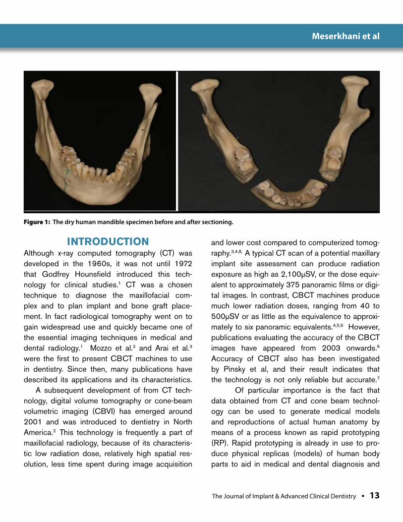
Figure 1: The dry human mandible specimen before and after sectioning.
Meserkhani et al
14 • Vol. 10, No. 1 • January 2018
treatment planning. In fact, with the first gen-eration of rapid prototyping models, computer-aided design (CAD) was used to translate the 3-D data into physical models by milling solid
blocks of Styrofoam or polyurethane. A leading technology for rapid prototyping in recent years has been Stereolithography or (SLA). Stereo-lithography creates 3-D models by selectively
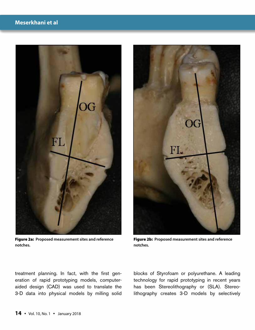
Figure 2a: Proposed measurement sites and reference notches.
Figure 2b: Proposed measurement sites and reference notches.
Meserkhani et al
The Journal of Implant & Advanced Clinical Dentistry • 15
solidifying UV-sensitive liquid acrylic resin using a laser beam.10 The technology has gained a great amount of attention, particularly in oral and maxillofacial surgery.11 An important and ongo-
ing challenge in RP applications in this field is how to produce RP models that are complete and anatomically accurate for each patient.
In previously reported investigations on the
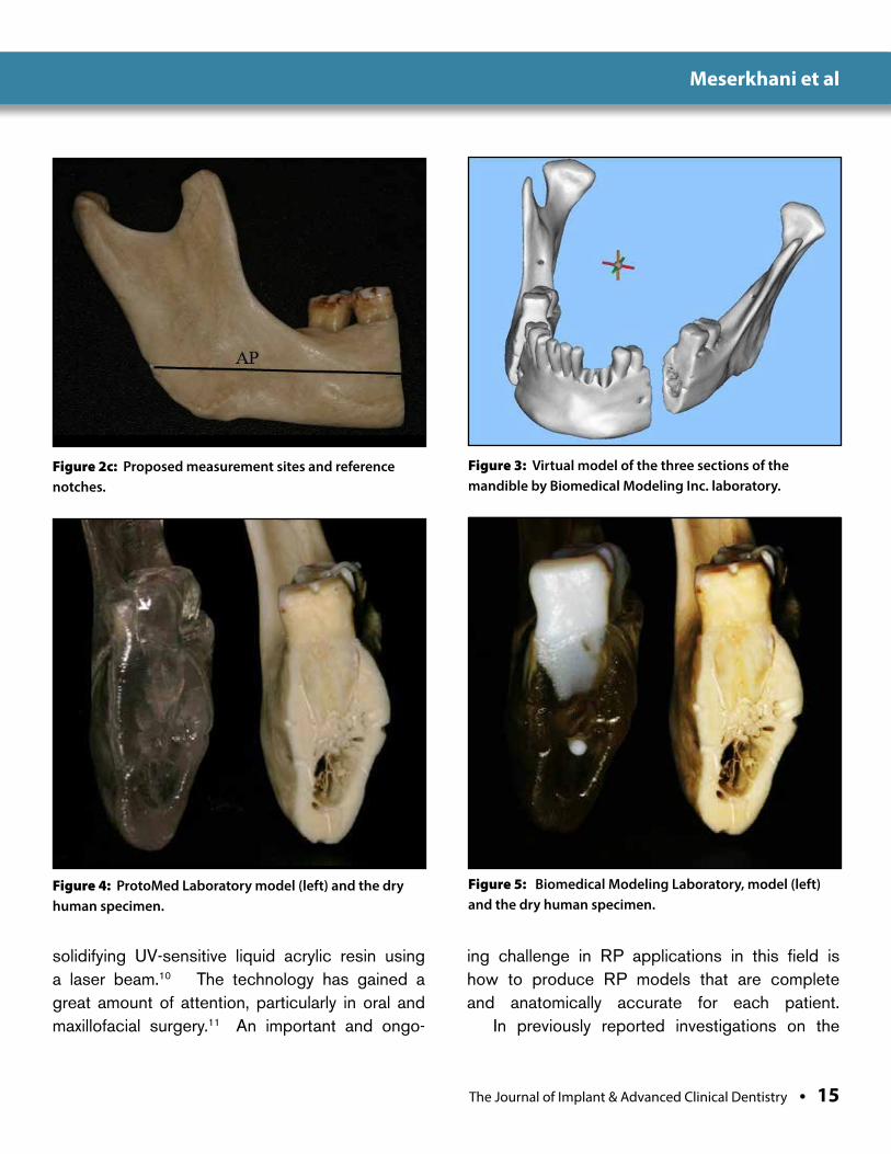
Figure 2c: Proposed measurement sites and reference notches.
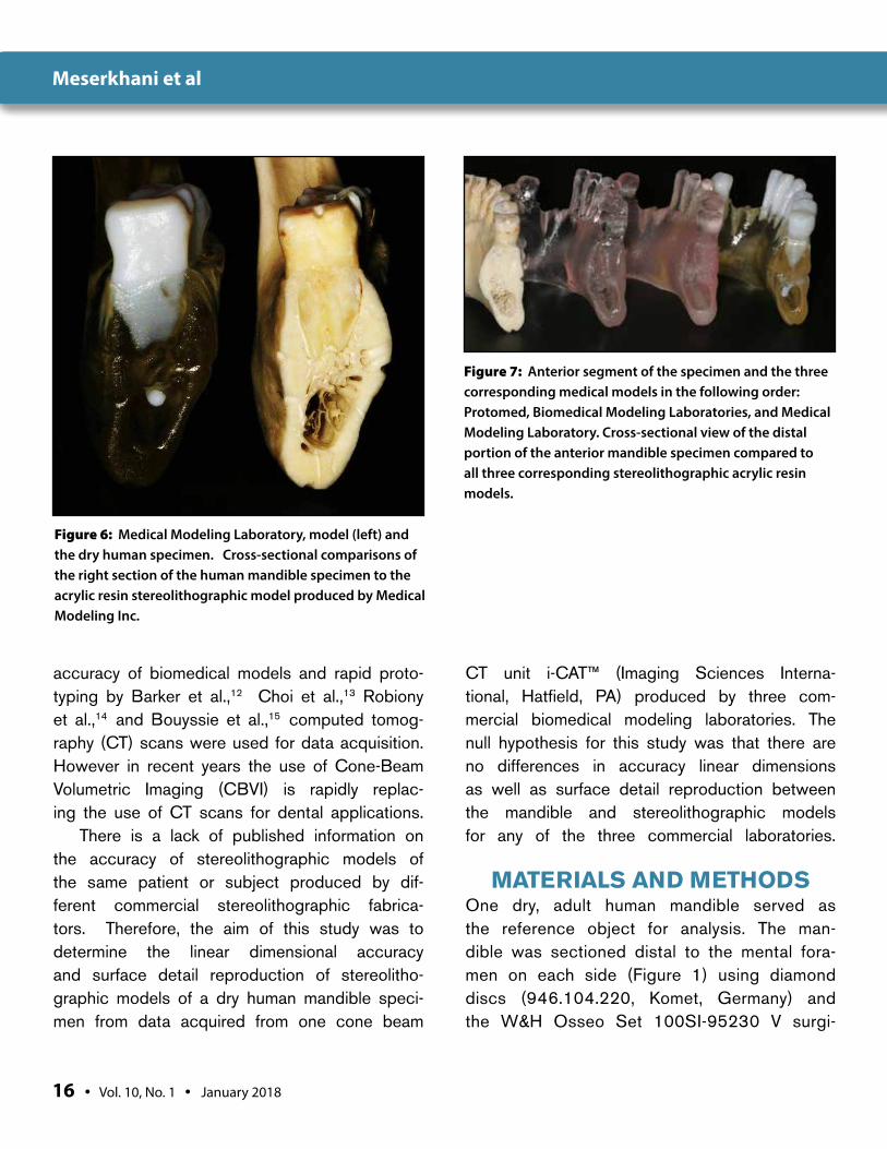
Figure 3: Virtual model of the three sections of the mandible by Biomedical Modeling Inc. laboratory.
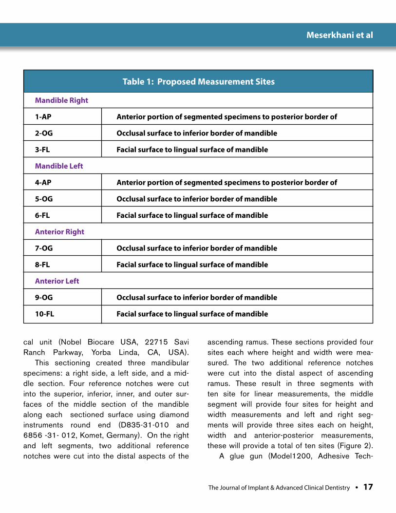
Figure 4: ProtoMed Laboratory model (left) and the dry human specimen.
Figure 5: Biomedical Modeling Laboratory, model (left) and the dry human specimen.
Meserkhani et al
16 • Vol. 10, No. 1 • January 2018
accuracy of biomedical models and rapid proto-typing by Barker et al.,12 Choi et al.,13 Robiony et al.,14 and Bouyssie et al.,15 computed tomog-raphy (CT) scans were used for data acquisition. However in recent years the use of Cone-Beam Volumetric Imaging (CBVI) is rapidly replac-ing the use of CT scans for dental applications.
There is a lack of published information on the accuracy of stereolithographic models of the same patient or subject produced by dif-ferent commercial stereolithographic fabrica-tors. Therefore, the aim of this study was to determine the linear dimensional accuracy and surface detail reproduction of stereolitho-graphic models of a dry human mandible speci-men from data acquired from one cone beam
CT unit i-CAT™ (Imaging Sciences Interna-tional, Hatfield, PA) produced by three com-mercial biomedical modeling laboratories. The null hypothesis for this study was that there are no differences in accuracy linear dimensions as well as surface detail reproduction between the mandible and stereolithographic models for any of the three commercial laboratories.
MATERIALS AND METHODSOne dry, adult human mandible served as the reference object for analysis. The man-dible was sectioned distal to the mental fora-men on each side (Figure 1) using diamond discs (946.104.220, Komet, Germany) and the W&H Osseo Set 100SI-95230 V surgi-
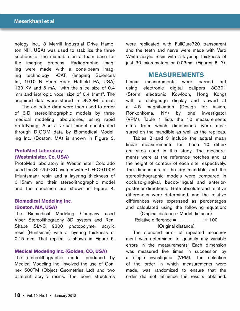
Figure 6: Medical Modeling Laboratory, model (left) and the dry human specimen. Cross-sectional comparisons of the right section of the human mandible specimen to the acrylic resin stereolithographic model produced by Medical Modeling Inc.
Figure 7: Anterior segment of the specimen and the three corresponding medical models in the following order: Protomed, Biomedical Modeling Laboratories, and Medical Modeling Laboratory. Cross-sectional view of the distal portion of the anterior mandible specimen compared to all three corresponding stereolithographic acrylic resin models.
Meserkhani et al
The Journal of Implant & Advanced Clinical Dentistry • 17
cal unit (Nobel Biocare USA, 22715 Savi Ranch Parkway, Yorba Linda, CA, USA).
This sectioning created three mandibular specimens: a right side, a left side, and a mid-dle section. Four reference notches were cut into the superior, inferior, inner, and outer sur-faces of the middle section of the mandible along each sectioned surface using diamond instruments round end (D835-31-010 and 6856 -31- 012, Komet, Germany). On the right and left segments, two additional reference notches were cut into the distal aspects of the
ascending ramus. These sections provided four sites each where height and width were mea-sured. The two additional reference notches were cut into the distal aspect of ascending ramus. These result in three segments with ten site for linear measurements, the middle segment will provide four sites for height and width measurements and left and right seg-ments will provide three sites each on height, width and anterior-posterior measurements, these will provide a total of ten sites (Figure 2).
A glue gun (Model1200, Adhesive Tech-
Table 1: Proposed Measurement Sites
Mandible Right
1-AP Anterior portion of segmented specimens to posterior border of
2-OG Occlusal surface to inferior border of mandible
3-FL Facial surface to lingual surface of mandible
Mandible Left
4-AP Anterior portion of segmented specimens to posterior border of
5-OG Occlusal surface to inferior border of mandible
6-FL Facial surface to lingual surface of mandible
Anterior Right
7-OG Occlusal surface to inferior border of mandible
8-FL Facial surface to lingual surface of mandible
Anterior Left
9-OG Occlusal surface to inferior border of mandible
10-FL Facial surface to lingual surface of mandible
Meserkhani et al
18 • Vol. 10, No. 1 • January 2018
nology Inc., 3 Merrill Industrial Drive Hamp-ton NH, USA) was used to stabilize the three sections of the mandible on a foam base for the imaging process. Radiographic imag-ing were made with a cone-beam imag-ing technology i-CAT, (Imaging Sciences Int, 1910 N Penn Road Hatfield PA, USA) 120 KV and 5 mA, with the slice size of 0.4 mm and isotropic voxel size of 0.4 (mm)3. The acquired data were stored in DICOM format.
The collected data were then used to order of 3-D stereolithographic models by three medical modeling laboratories, using rapid prototyping. Also a virtual model constructed through DICOM data by Biomedical Model-ing Inc. (Boston, MA) is shown in Figure 3.
ProtoMed Laboratory (Westminister, Co, USA)ProtoMed laboratory in Westminster Colorado used the SL-250 3D system with SL H-C9100R (Huntsman) resin and a layering thickness of 0.15mm and their stereolithographic model and the specimen are shown in Figure 4.
Biomedical Modeling Inc. (Boston, MA, USA) The Biomedical Modeling Company used Viper Stereolithography 3D system and Ren-Shape SLY-C 9300 photopolymer acrylic resin (Huntsman) with a layering thickness of 0.15 mm. That replica is shown in Figure 5.
Medical Modeling Inc. (Golden, CO, USA)The stereolithographic model produced by Medical Modeling Inc. involved the use of Con-nex 500TM (Object Geometries Ltd) and two different acrylic resins. The bone structures
were replicated with FullCure720 transparent and the teeth and nerve were made with Vero White acrylic resin with a layering thickness of just 30 micrometers or 0.03mm (Figures 6, 7).
MEASUREMENTSLinear measurements were carried out using electronic digital calipers 3C301 (Storm electronic Kowloon, Hong Kong) with a dial-gauge display and viewed at a 4.5 magnification (Design for Vision, Ronkonkoma, NY) by one investigator (VPM). Table 1 lists the 10 measurements sites from which dimensions were mea-sured on the mandible as well as the replicas.
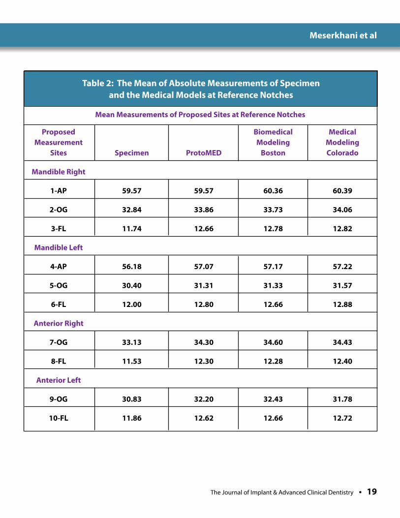
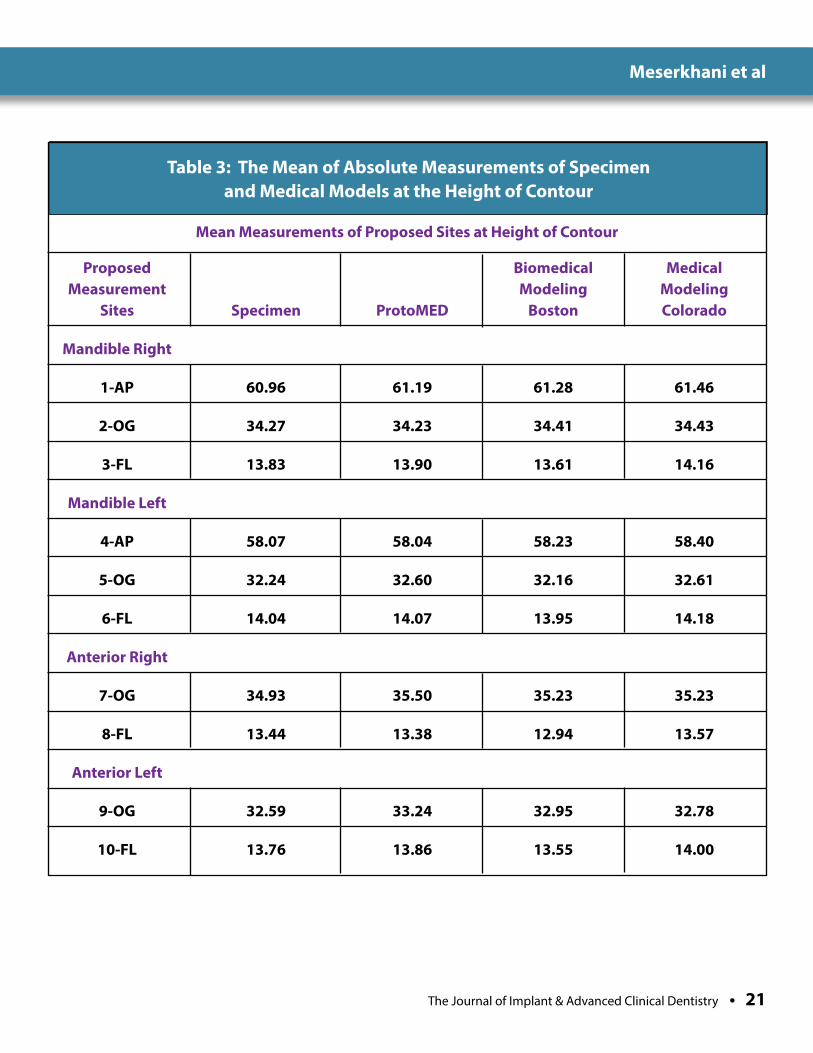
Tables 2 and 3 include the actual mean linear measurements for those 10 differ-ent sites used in this study. The measure-ments were at the reference notches and at the height of contour of each site respectively. The dimensions of the dry mandible and the stereolithographic models were compared in occluso-gingival, bucco-lingual and anterior-posterior directions. Both absolute and relative differences were determined, and the relative differences were expressed as percentages and calculated using the following equation:
(Original distance - Model distance)Relative difference = ------------------- × 100
(Original distance)The standard error of repeated measure-
ment was determined to quantify any variable errors in the measurements. Each dimension was measured five times in succession by a single investigator (VPM). The selection of the order in which measurements were made, was randomized to ensure that the order did not influence the results obtained.
Meserkhani et al
The Journal of Implant & Advanced Clinical Dentistry • 19
Table 2: The Mean of Absolute Measurements of Specimen and the Medical Models at Reference Notches
Proposed Biomedical Medical Measurement Modeling Modeling Sites Specimen ProtoMED Boston Colorado
Mandible Right
1-AP 59.57 59.57 60.36 60.39
2-OG 32.84 33.86 33.73 34.06
3-FL 11.74 12.66 12.78 12.82
Mandible Left
4-AP 56.18 57.07 57.17 57.22
5-OG 30.40 31.31 31.33 31.57
6-FL 12.00 12.80 12.66 12.88
Anterior Right
7-OG 33.13 34.30 34.60 34.43
8-FL 11.53 12.30 12.28 12.40
Anterior Left
9-OG 30.83 32.20 32.43 31.78
10-FL 11.86 12.62 12.66 12.72
Mean Measurements of Proposed Sites at Reference Notches
Meserkhani et al
20 • Vol. 10, No. 1 • January 2018
The measurements were made in the following manner: 1. Each section of the mandibular specimens
was measured followed by the same location on each of the three corresponding medical models.
2. Five successive measurement readings were collected in the occluso-gingival and facial-lingual dimensions at the sectioned surfaces.
3. Two additional measurements were made at the anterio-posterior aspects of the right and left segments for the mandible and the three ste-reolithographic replicas. These readings were recorded using the reference notches and at the height of contour of each proposed site.
STATISTICAL ANALYSIS A one- way analysis of variance (ANOVA) was use with the stereolithographic models as a fac-tor for comparison. The Least Squared Dif-ferences (LSD) tests were used for post hoc comparisons. All tests were considered to be significant at an alpha level of p < 0.05.
RESULTSComparisons of the three human mandible specimens, using the reference notches, with their corresponding medical models at the 10 different sites showed statistically signifi-cant differences between the specimens and medical models when the reference notches were used for measurement. Based on the F and P-value, at 5% level of significance (α = 0.05), the null hypothesis was rejected, not all of the means were statistically equal.
However, when the heights of contour of the same sites were used 6 out of ten sites with Pro-tomed Laboratory, 4 out of ten sites with Biomedi-
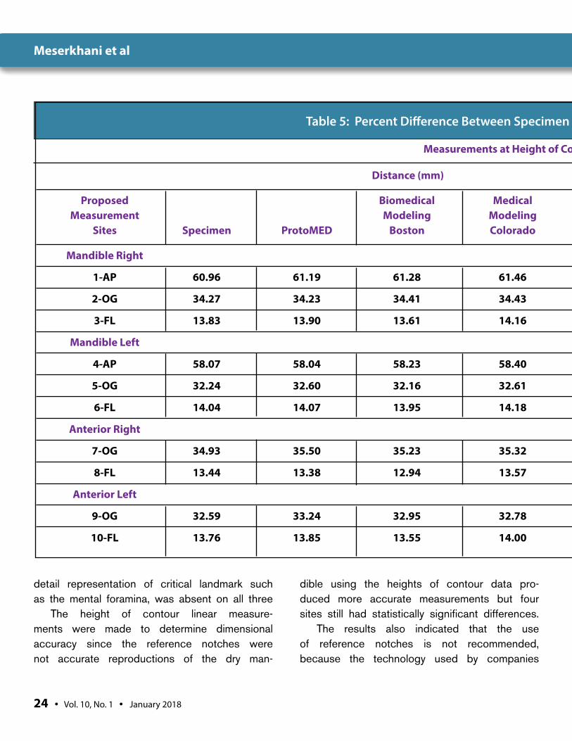
cal Modeling laboratory and 3 out of ten sites with Medical modeling laboratory had no significant differences. The heights of contour comparisons indicated that medical models were dimensionally accurate only in thirteen out of 30 sites measured.
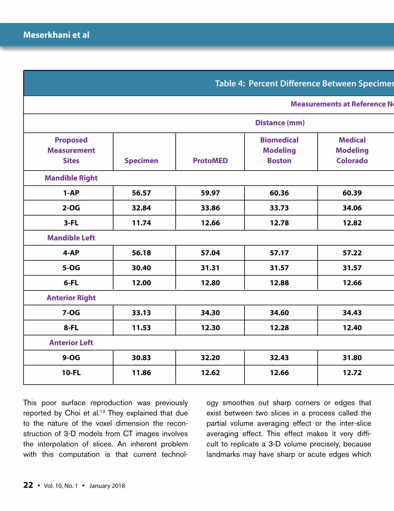
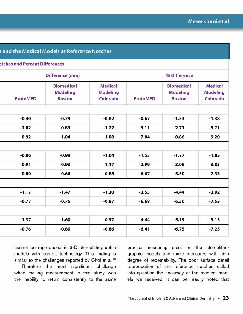
Relative differences between the man-dibular specimens and each the three corre-sponding medical models were calculated to determine the difference in mm and percent-age errors. Table 4 includes the mean of abso-lute distances, the difference in mm and the relative differences by percentage for measure-ments at the reference notches. Table 5 lists the mean of absolute distances, the difference in mm and the relative differences by percent-age for measurements at the height of contour.
DISCUSSIONThe value of biomedical modeling in evaluating craniofacial anomalies and maxillofacial recon-structive surgeries have been extensively dis-cussed by several authors.16,17,18,19 In fact in recent years multiple articles have been pub-lished regarding implant placement using stereolithographic surgical guides.20,21,22
It is the opinion of the authors that both the dimensions of stereolithographic models and their detail reproduction are important characteristics that can affect the outcome of sensitive surger-ies such as implant guided surgery and immedi-ate placement of implant prostheses. A review of all three types of medical models revealed signifi-cant variations in the level of detail captured at the pre-determined reference notches as well as the natural anatomical landmarks found in a mandible.
Proper measurement of the models was a challenge, because the reference notches were missing or poorly reproduced on all the models.
Meserkhani et al
The Journal of Implant & Advanced Clinical Dentistry • 21
Table 3: The Mean of Absolute Measurements of Specimen and Medical Models at the Height of Contour
Proposed Biomedical Medical Measurement Modeling Modeling Sites Specimen ProtoMED Boston Colorado
Mandible Right
1-AP 60.96 61.19 61.28 61.46
2-OG 34.27 34.23 34.41 34.43
3-FL 13.83 13.90 13.61 14.16
Mandible Left
4-AP 58.07 58.04 58.23 58.40
5-OG 32.24 32.60 32.16 32.61
6-FL 14.04 14.07 13.95 14.18
Anterior Right
7-OG 34.93 35.50 35.23 35.23
8-FL 13.44 13.38 12.94 13.57
Anterior Left
9-OG 32.59 33.24 32.95 32.78
10-FL 13.76 13.86 13.55 14.00
Mean Measurements of Proposed Sites at Height of Contour
Meserkhani et al
22 • Vol. 10, No. 1 • January 2018
Table 4: Percent Difference Between Specimen and the Medical Models at Reference Notches
Distance (mm) Difference (mm) % Difference
Proposed Biomedical Medical Biomedical Medical Biomedical Medical Measurement Modeling Modeling Modeling Modeling Modeling Modeling Sites Specimen ProtoMED Boston Colorado ProtoMED Boston Colorado ProtoMED Boston Colorado
Mandible Right
1-AP 56.57 59.97 60.36 60.39 -0.40 -0.79 -0.82 -0.67 -1.33 -1.38
2-OG 32.84 33.86 33.73 34.06 -1.02 -0.89 -1.22 -3.11 -2.71 -3.71
3-FL 11.74 12.66 12.78 12.82 -0.92 -1.04 -1.08 -7.84 -8.86 -9.20
Mandible Left
4-AP 56.18 57.04 57.17 57.22 -0.86 -0.99 -1.04 -1.53 -1.77 -1.85
5-OG 30.40 31.31 31.57 31.57 -0.91 -0.93 -1.17 -2.99 -3.06 -3.85
6-FL 12.00 12.80 12.88 12.66 -0.80 -0.66 -0.88 -6.67 -5.50 -7.33
Anterior Right
7-OG 33.13 34.30 34.60 34.43 -1.17 -1.47 -1.30 -3.53 -4.44 -3.92
8-FL 11.53 12.30 12.28 12.40 -0.77 -0.75 -0.87 -6.68 -6.50 -7.55
Anterior Left
9-OG 30.83 32.20 32.43 31.80 -1.37 -1.60 -0.97 -4.44 -5.19 -3.15
10-FL 11.86 12.62 12.66 12.72 -0.76 -0.80 -0.86 -6.41 -6.75 -7.25
Measurements at Reference Notches and Percent Differences
This poor surface reproduction was previously reported by Choi et al.13 They explained that due to the nature of the voxel dimension the recon-struction of 3-D models from CT images involves the interpolation of slices. An inherent problem with this computation is that current technol-
ogy smoothes out sharp corners or edges that exist between two slices in a process called the partial volume averaging effect or the inter-slice averaging effect. This effect makes it very diffi-cult to replicate a 3-D volume precisely, because landmarks may have sharp or acute edges which
Meserkhani et al
The Journal of Implant & Advanced Clinical Dentistry • 23
Table 4: Percent Difference Between Specimen and the Medical Models at Reference Notches
Distance (mm) Difference (mm) % Difference
Proposed Biomedical Medical Biomedical Medical Biomedical Medical Measurement Modeling Modeling Modeling Modeling Modeling Modeling Sites Specimen ProtoMED Boston Colorado ProtoMED Boston Colorado ProtoMED Boston Colorado
Mandible Right
1-AP 56.57 59.97 60.36 60.39 -0.40 -0.79 -0.82 -0.67 -1.33 -1.38
2-OG 32.84 33.86 33.73 34.06 -1.02 -0.89 -1.22 -3.11 -2.71 -3.71
3-FL 11.74 12.66 12.78 12.82 -0.92 -1.04 -1.08 -7.84 -8.86 -9.20
Mandible Left
4-AP 56.18 57.04 57.17 57.22 -0.86 -0.99 -1.04 -1.53 -1.77 -1.85
5-OG 30.40 31.31 31.57 31.57 -0.91 -0.93 -1.17 -2.99 -3.06 -3.85
6-FL 12.00 12.80 12.88 12.66 -0.80 -0.66 -0.88 -6.67 -5.50 -7.33
Anterior Right
7-OG 33.13 34.30 34.60 34.43 -1.17 -1.47 -1.30 -3.53 -4.44 -3.92
8-FL 11.53 12.30 12.28 12.40 -0.77 -0.75 -0.87 -6.68 -6.50 -7.55
Anterior Left
9-OG 30.83 32.20 32.43 31.80 -1.37 -1.60 -0.97 -4.44 -5.19 -3.15
10-FL 11.86 12.62 12.66 12.72 -0.76 -0.80 -0.86 -6.41 -6.75 -7.25
Measurements at Reference Notches and Percent Differences
cannot be reproduced in 3-D stereolithographic models with current technology. This finding is similar to the challenges reported by Choi et al.13
Therefore the most significant challenge when making measurement in this study was the inability to return consistently to the same
precise measuring point on the stereolitho-graphic models and make measures with high degree of repeatability. The poor surface detail reproduction of the reference notches called into question the accuracy of the medical mod-els we received. It can be readily noted that
Meserkhani et al
24 • Vol. 10, No. 1 • January 2018
Table 5: Percent Difference Between Specimen and the Medical Models at the Height of Contour
Distance (mm) Difference (mm) % Difference
Proposed Biomedical Medical Biomedical Medical Biomedical Medical Measurement Modeling Modeling Modeling Modeling Modeling Modeling Sites Specimen ProtoMED Boston Colorado ProtoMED Boston Colorado ProtoMED Boston Colorado
Mandible Right
1-AP 60.96 61.19 61.28 61.46 -0.23 -0.32 -0.50 -0.38 -0.52 -0.82
2-OG 34.27 34.23 34.41 34.43 -0.04 -0.14 -0.16 0.12 -0.41 -0.47
3-FL 13.83 13.90 13.61 14.16 -0.07 0.22 -0.33 -0.51 1.59 -2.39
Mandible Left
4-AP 58.07 58.04 58.23 58.40 0.03 -0.16 -0.33 0.05 -0.28 -0.57
5-OG 32.24 32.60 32.16 32.61 -0.36 0.08 -0.37 -1.12 0.25 -1.15
6-FL 14.04 14.07 13.95 14.18 -0.03 0.09 -0.14 -0.21 0.64 -1.00
Anterior Right
7-OG 34.93 35.50 35.23 35.32 -0.57 -0.30 -0.39 -1.63 -0.86 -1.12
8-FL 13.44 13.38 12.94 13.57 -0.06 0.50 -0.13 0.45 3.72 -0.97
Anterior Left
9-OG 32.59 33.24 32.95 32.78 -0.65 -0.36 -0.19 -1.99 -1.10 -0.58
10-FL 13.76 13.85 13.55 14.00 -0.10 0.21 -0.24 -0.73 1.53 -1.74
Measurements at Height of Contour and Percent Differences
detail representation of critical landmark such as the mental foramina, was absent on all three
The height of contour linear measure-ments were made to determine dimensional accuracy since the reference notches were not accurate reproductions of the dry man-
dible using the heights of contour data pro-duced more accurate measurements but four sites still had statistically significant differences.
The results also indicated that the use of reference notches is not recommended, because the technology used by companies
Meserkhani et al

The Journal of Implant & Advanced Clinical Dentistry • 25
Table 5: Percent Difference Between Specimen and the Medical Models at the Height of Contour
Distance (mm) Difference (mm) % Difference
Proposed Biomedical Medical Biomedical Medical Biomedical Medical Measurement Modeling Modeling Modeling Modeling Modeling Modeling Sites Specimen ProtoMED Boston Colorado ProtoMED Boston Colorado ProtoMED Boston Colorado
Mandible Right
1-AP 60.96 61.19 61.28 61.46 -0.23 -0.32 -0.50 -0.38 -0.52 -0.82
2-OG 34.27 34.23 34.41 34.43 -0.04 -0.14 -0.16 0.12 -0.41 -0.47
3-FL 13.83 13.90 13.61 14.16 -0.07 0.22 -0.33 -0.51 1.59 -2.39
Mandible Left
4-AP 58.07 58.04 58.23 58.40 0.03 -0.16 -0.33 0.05 -0.28 -0.57
5-OG 32.24 32.60 32.16 32.61 -0.36 0.08 -0.37 -1.12 0.25 -1.15
6-FL 14.04 14.07 13.95 14.18 -0.03 0.09 -0.14 -0.21 0.64 -1.00
Anterior Right
7-OG 34.93 35.50 35.23 35.32 -0.57 -0.30 -0.39 -1.63 -0.86 -1.12
8-FL 13.44 13.38 12.94 13.57 -0.06 0.50 -0.13 0.45 3.72 -0.97
Anterior Left
9-OG 32.59 33.24 32.95 32.78 -0.65 -0.36 -0.19 -1.99 -1.10 -0.58
10-FL 13.76 13.85 13.55 14.00 -0.10 0.21 -0.24 -0.73 1.53 -1.74
Measurements at Height of Contour and Percent Differences
in this study cannot replicate these features in the stereolithographic models they produce.
Previous investigations such as Baker et al.12 and Choi et al.13 used CT imaging rather than cone beam technology. Because more dental clinicians are incorporating cone beam
technology into their practices, additional research is needed into the use of CBCT data in the fabrication of stereolithographic mod-els. Additionally, future studies should com-pare the accuracy of different cone beam units.
Meserkhani et al
26 • Vol. 10, No. 1 • January 2018
CONCLUSIONStereolithographic models fabricated using data from one cone beam unit were dimensionally accurate in thirteen out of 30 sites when heights of contour measurements were made. How-ever, surface details were not recorded at a level that permitted accurate replication of the refer-ence notches. Consequently, none of the stereo-lithographic models manufactured by the three companies included in this pilot study could be used to make accurate linear measurements to assess dimensional accuracy. The accuracy of
stereolithographic models might not be so sig-nificant in pre-surgical assessments of surgical site but the accuracy of biomedical models could be very critical in procedures such as guided implant surgeries and the assessment of the prosthesis in immediate loading techniques. l
Correspondence:Dr. Tony [email protected]
AcknowledgmentsThe authors want to acknowledge the contribution of Dr. Hamid Pourmohammadi for assistance with the statistical analyses. Also, the authors want to thank Dr. Patrick Naylor in helping and editing this manuscript.
DisclosureThe authors report no conflicts of interest with anything in this paper.
References1. Zoller JE, Neugebauer J. Cone-beam Volumetric
Imaging in Dental, Oral and Maxillofacial Medicine. Fundamentals, Diagnostic and Treatment Planning Quintessence Pub Ltd 2008
2. Mozzo P, Procacci C, Tacconi A, Martini PT, Andreis IA. A new volumetric CT machine for dental imaging based on the cone-beam technique: preliminary results. Eur Radiol 1998; 8: 1558-1564.
3. Arai Y, Tammisalo E, Iwai K, Hashimoto K, Shinoda K. Development of compact computed tomographic apparatus for dental use. Dentomaxillofac Radiol 1999; 28: 245-248.
4. Winter AA, Pollack AS, Frommer HH, Koenig L. Cone beam volumetric tomography vs. medical CT scanners. NY State Dent J. 2005 Jun-Jul;71(4):28-33.
5. Hashimoto K, Arai Y, Iwai K, Araki M, Kawashima S, Terakado M. A comparison of new limited cone beam computed tomography machine for dental use and multidetector row helical CT machine. Oral Surg Oral Med Oral Pathol Oral Radiol Endod 2003; 95:371-377.
6. Panzarella FK, Junqueira JLC, Oliveira LB, de Araujo NS, Costa C. Accuracy assessment of the axial images obtained from cone beam computed tomography. Dentomaxillo Radiol 2011; 40:369-378
7. Pinsky HM, Dyda S, Pinsky RW, Misch KA, Sarment DP. Accuracy of three-dimensional measurements using cone-beam CT. DentoMaxfac Rad; 2006; 35:410-416.
8. Miles DA, Danforth RA, A clinician’s guide to understanding cone beam volumetric imaging (CBVI) CE Course published by Academy of Dental Therapeutics and Stomatology 2007.
9. Ludlow JB, Davies-Ludlow LE, Brooks SL, Howerton WB. Dosimetry of 3 CBCT devices for oral and maxillofacial radiology: CB Mercury, NewTom 3G, and i-CAT. Dentomaxillofac Radiol.2006:35:219-226.
10. McGurk M, Potamianos P, Amis AA, Goodger NM, Rapid prototyping techniques for anatomical modeling in medicine. Ann R Coll Surg Engl 1997; 79: 169-174.
11. Lambrecht JT. Modeling technology in maxillofacial surgery. Place: Quintessence Books 1995: 61-64, 72-75, 132-135.
12. Barker TM, Earwaker WJS, Lisle DA. Accuracy of stereolithographic models of human anatomy. Australasian Radiol 1994: 38; 106-111.
13. Choi JY, Choi JH, Kim NK, Kim Y, Lee JK, Kim MK, Lee JH, Kim MJ. Analysis of errors in medical rapid prototyping models. Int J Maxillofacial Surg 2002: 31; 23-32.
14. Robiony M, Salvo I, Costa F, Zerman N, Bandera C, Filippi S, Felice M, Politi M. Accuracy of virtual reality and stereolithographic models in maxillo-facial surgical planning. J of Craniofacial Surg2008:19; 482-489.
15. Bouyssie, J.F., Bouyssie, S., Sharrock, P., Duran, D. Stereolithographic models derived from x-ray computed tomography, Reproduction accuracy. Surg Radiol. Anat., 1997: Vol. 19 No.3, pp. 193-199.
16. Kragskov J, Sindet-Pedersen S, Gyldensted C, Jensen KL. A comparison of three-dimensional computed tomography scans and stereolithographic model for evaluation of craniofacial anomalies. J Oral Maxillofacial Surg 1996:54; 402-411.
17. Lill W, Solar P, Ulm C, Watzek G, Blahout R, Matejka M. Reproducibility of three-dimensional CT-assisted model production in the maxillofacial area. Br J Oral Maxillofacial Surg 1992: 30; 233-236.
18. Cheng A, Wee A. Reconstruction of cranial bone defects using alloplastic implants produced from stereolithographically generated cranial model. Ann Acad Med 1999; 20:692-696.
19. Erickson D, Chance D, Schmitt S, Mathis J. An opinion survey of reported benefits from the use of stereolithographic models. J Oral Maxillofacial Surg 1999; 57:1040-1043.
20. Sarment D, Sukovic P, Clinthorne N. Accuracy of implant placement with a stereolithographic surgical guide. Int J Oral Maxillofac Implants 2003; 18:571-577.
21. Rosenfeld A, Mandelaris G, Tardieu P, Prosthetically directed implant placement using computer software to ensure precise placement and predictable prosthetic outcome. Part 1: Diagnostics, imaging, and collaborative accountability. Int J Periodontics Restorative Dent 2006; 26:215-221.
22. Rosenfeld A, Mandelaris G, Tardieu P, Prosthetically directed implant placement using computer software to ensure precise placement and predictable prosthetic outcome. Part 2: Rapid prototype medical modeling and stereolithographic drilling guide requiring bone exposure. Int J Periodontics Restorative Dent 2006; 26:347-353.
Meserkhani et al
The Journal of Implant & Advanced Clinical Dentistry • XX
Meserkhani et al
Bolli et al
Background: Severe maxillary atrophy frequently limits dental implant placement. In the presence of a protruding palatal torus, such a situation may fur-ther condition the final prosthetic reconstruction.
Methods: An edentulous patient with a severely resorbed alveolar ridge and a big palatal torus was treated. A ridge splitting crest technique was used and four 3.3 mm wide by 10 mm long implants (Lance, MIS®) were immediately inserted. The space between the implants and the bone disjunction was filled with particles of autog-enous bone and bovine bone without membrane.
Results: The width of the average preoperative alveolar ridge measured in the CBCT was 2.8 mm and increased to 5.2 mm 5 years after surgery.
Conclusions: This technique allows the volume to be increased horizontally and the simultane-ous placement of the implants, being highly pre-dictable, safe and comfortable for the patient, with no need for a donor site which may cause greater morbidity or postoperative complications
Ridge Splitting Crest Technique and Simultaneous Implant Placement in a Patient with Severe Maxillary
Ridge Atrophy and Palatal Torus: A Case Report
Dr. Ezequiel Bolli1 • Dr. Guillermo Schinini1 • Dr. Hugo Romanelli1
1. Department of Postgraduate Periodontology, Maimónides University, Bs As, Argentina
Abstract
KEY WORDS: Dental implant, ridge split, bone augmentation, palatal torus
28 • Vol. 10, No. 1 • January 2018
Bolli et al
The Journal of Implant & Advanced Clinical Dentistry • 29
Bolli et al
INTRODUCTIONOver the last few decades, implant place-ment in partially or fully edentulous patients has become a reliable technique with suc-cessful long-term outcomes. However, in fully edentulous patients with a severely resorbed alveolar ridge and a protruding palatal torus, it may pose certain limitations and a major chal-lenge for the future prosthetic rehabilitation.1
Palatal tori in dentate patients do not pro-duce any functional modifications. Neverthe-less, due to the loss of the teeth over the years and without early treatment with implants, prob-lems begin in the use of removable partial appli-ances, since their design must avoid contact with the palatal torus.2 When the loss of bone exceeds the retention that the appliances may exert, it will be necessary to make mucosal abut-ments that will eventually determine greater resorption of the bony pre-maxilla by compres-sion since there is no palatal abutment, which is responsible for withstanding the compression and distributing the strengths.2 As a result, patients will become fully edentulous with atrophic maxil-lae both vertically and horizontally, making it dif-ficult or impossible to place dental implants.3 In these cases, Guided Bone Regeneration (GBR) or block bone grafts become relevant.4,5
Both methods present numerous limitations or drawbacks to increase the maxilla ridge width, such as: secondary donor site, higher morbidity, resorption of the grafted material, and membrane collapse/exposure which increases the chances of infection. These techniques are more invasive and require a longer waiting time for the grafted mate-rial to integrate, which will delay implant placement and treatment will therefore be longer.6 In order to avoid such limitations, an alternative might be the
maxilla bone disjunction, expansion of the alveolar bone plates and simultaneous implant placement. In 1992 Simion et al. and in 1994 Scipioni et al. proposed a surgical technique that split the alve-olar ridge longitudinally into two parts, creating a greenstick fracture where to place the implants.7,8 Nevertheless, this procedure does not come with-out postoperative complications, such as buc-cal wall fracture and ridge resorption, among the most typical ones. The following article describes implant placement in atrophic upper maxilla with a severe palatal torus using the split-crest technique by means of piezoelectric scalpel (Piezosurgery).
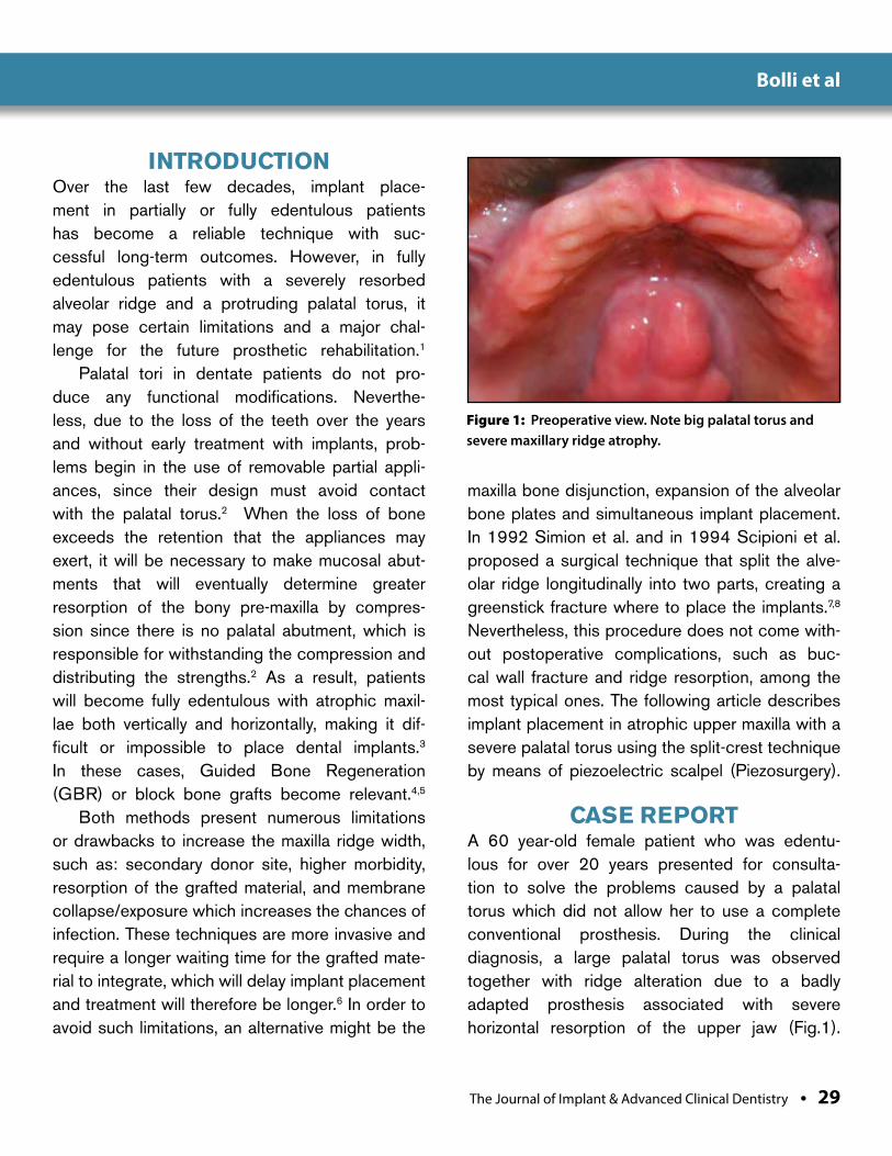
CASE REPORTA 60 year-old female patient who was edentu-lous for over 20 years presented for consulta-tion to solve the problems caused by a palatal torus which did not allow her to use a complete conventional prosthesis. During the clinical diagnosis, a large palatal torus was observed together with ridge alteration due to a badly adapted prosthesis associated with severe horizontal resorption of the upper jaw (Fig.1).
Figure 1: Preoperative view. Note big palatal torus and severe maxillary ridge atrophy.
30 • Vol. 10, No. 1 • January 2018
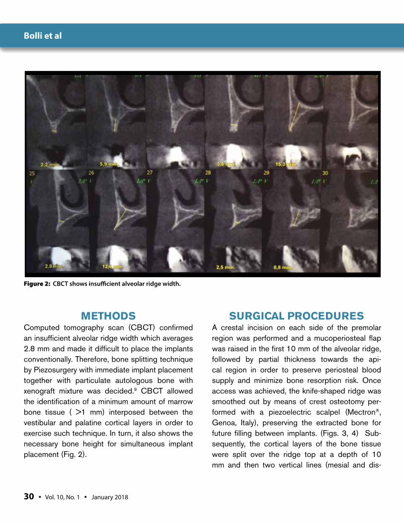
METHODSComputed tomography scan (CBCT) confirmed an insufficient alveolar ridge width which averages 2.8 mm and made it difficult to place the implants conventionally. Therefore, bone splitting technique by Piezosurgery with immediate implant placement together with particulate autologous bone with xenograft mixture was decided.9 CBCT allowed the identification of a minimum amount of marrow bone tissue ( >1 mm) interposed between the vestibular and palatine cortical layers in order to exercise such technique. In turn, it also shows the necessary bone height for simultaneous implant placement (Fig. 2).
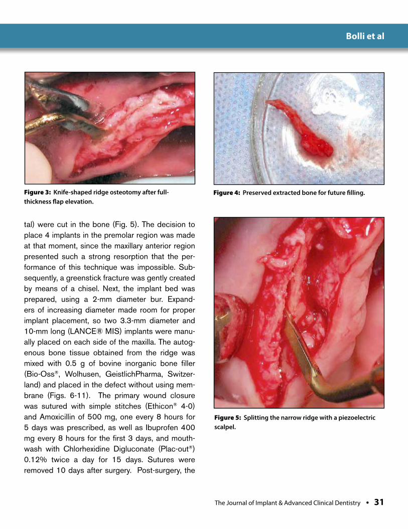
SURGICAL PROCEDURESA crestal incision on each side of the premolar region was performed and a mucoperiosteal flap was raised in the first 10 mm of the alveolar ridge, followed by partial thickness towards the api-cal region in order to preserve periosteal blood supply and minimize bone resorption risk. Once access was achieved, the knife-shaped ridge was smoothed out by means of crest osteotomy per-formed with a piezoelectric scalpel (Mectron®, Genoa, Italy), preserving the extracted bone for future filling between implants. (Figs. 3, 4) Sub-sequently, the cortical layers of the bone tissue were split over the ridge top at a depth of 10 mm and then two vertical lines (mesial and dis-
Figure 2: CBCT shows insufficient alveolar ridge width.
Bolli et al
The Journal of Implant & Advanced Clinical Dentistry • 31
tal) were cut in the bone (Fig. 5). The decision to place 4 implants in the premolar region was made at that moment, since the maxillary anterior region presented such a strong resorption that the per-formance of this technique was impossible. Sub-sequently, a greenstick fracture was gently created by means of a chisel. Next, the implant bed was prepared, using a 2-mm diameter bur. Expand-ers of increasing diameter made room for proper implant placement, so two 3.3-mm diameter and 10-mm long (LANCE® MIS) implants were manu-ally placed on each side of the maxilla. The autog-enous bone tissue obtained from the ridge was mixed with 0.5 g of bovine inorganic bone filler (Bio-Oss®, Wolhusen, GeistlichPharma, Switzer-land) and placed in the defect without using mem-brane (Figs. 6-11). The primary wound closure was sutured with simple stitches (Ethicon® 4-0) and Amoxicillin of 500 mg, one every 8 hours for 5 days was prescribed, as well as Ibuprofen 400 mg every 8 hours for the first 3 days, and mouth-wash with Chlorhexidine Digluconate (Plac-out®) 0.12% twice a day for 15 days. Sutures were removed 10 days after surgery. Post-surgery, the
Figure 3: Knife-shaped ridge osteotomy after full-thickness flap elevation.
Figure 4: Preserved extracted bone for future filling.
Figure 5: Splitting the narrow ridge with a piezoelectric scalpel.
Bolli et al
32 • Vol. 10, No. 1 • January 2018
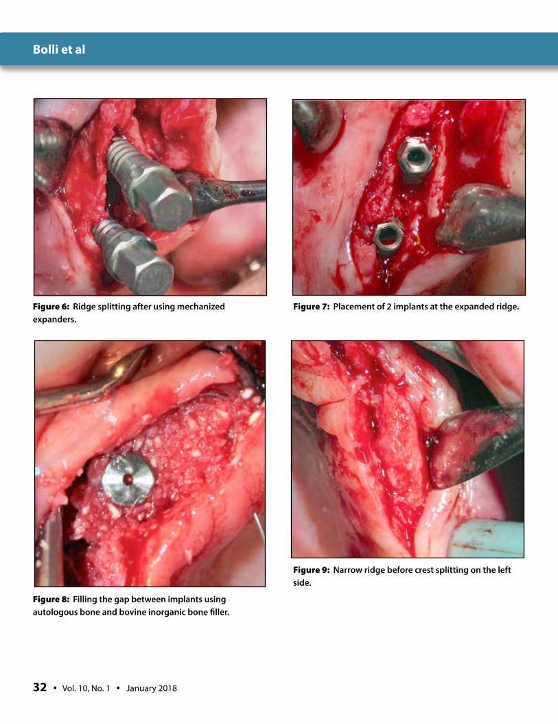
Figure 6: Ridge splitting after using mechanized expanders.
Figure 7: Placement of 2 implants at the expanded ridge.
Figure 8: Filling the gap between implants using autologous bone and bovine inorganic bone filler.
Figure 9: Narrow ridge before crest splitting on the left side.
Bolli et al
The Journal of Implant & Advanced Clinical Dentistry • 33
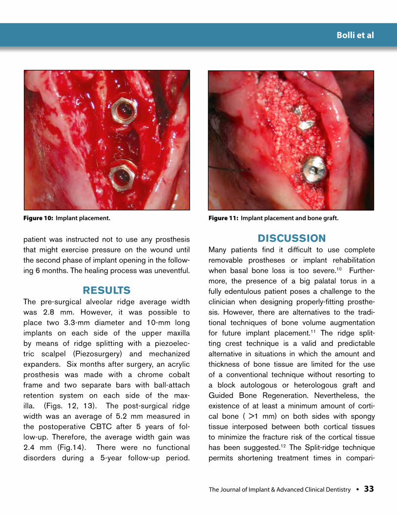
Figure 10: Implant placement. Figure 11: Implant placement and bone graft.
patient was instructed not to use any prosthesis that might exercise pressure on the wound until the second phase of implant opening in the follow-ing 6 months. The healing process was uneventful.
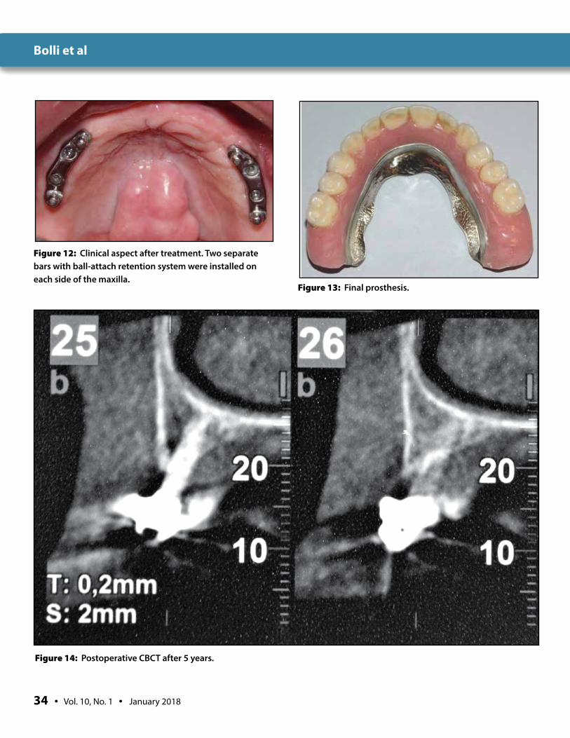
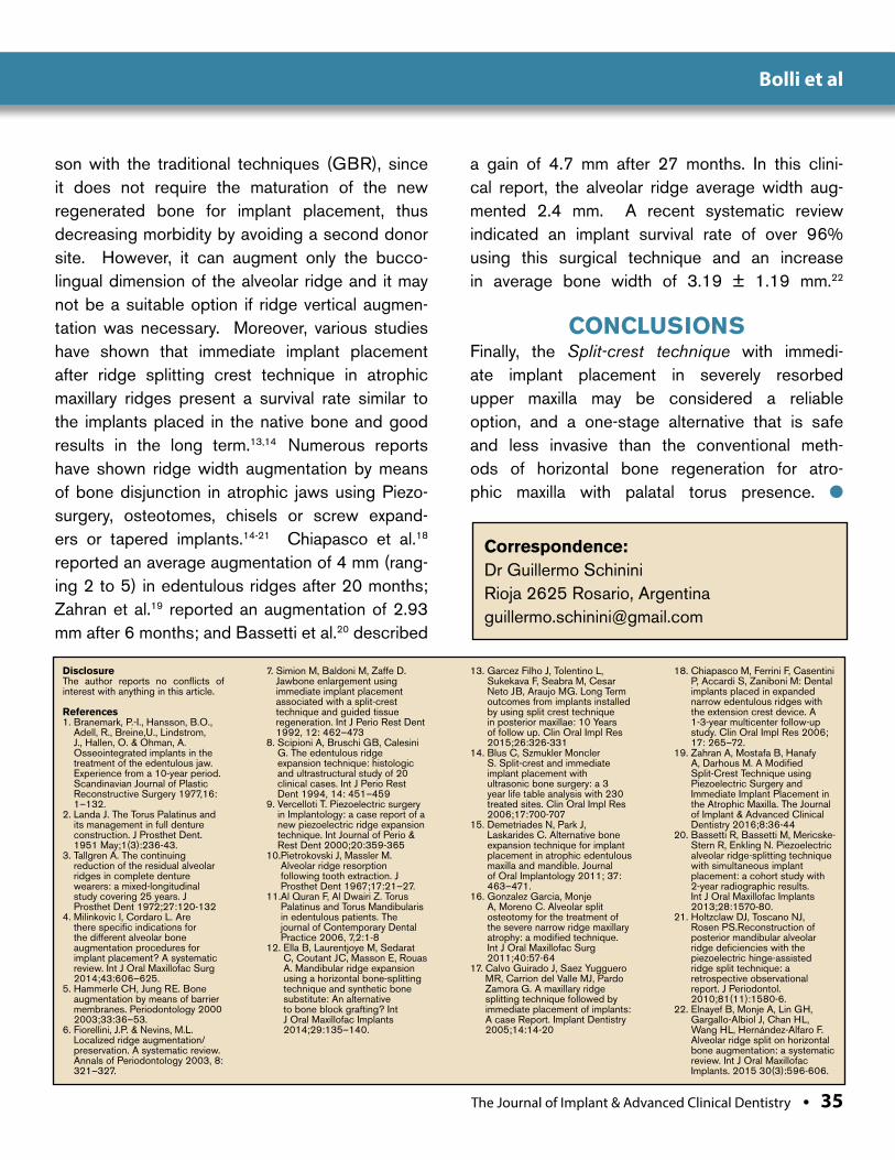
RESULTSThe pre-surgical alveolar ridge average width was 2.8 mm. However, it was possible to place two 3.3-mm diameter and 10-mm long implants on each side of the upper maxilla by means of ridge splitting with a piezoelec-tric scalpel (Piezosurgery) and mechanized expanders. Six months after surgery, an acrylic prosthesis was made with a chrome cobalt frame and two separate bars with ball-attach retention system on each side of the max-illa. (Figs. 12, 13). The post-surgical ridge width was an average of 5.2 mm measured in the postoperative CBTC after 5 years of fol-low-up. Therefore, the average width gain was 2.4 mm (Fig.14). There were no functional disorders during a 5-year follow-up period.
DISCUSSIONMany patients find it difficult to use complete removable prostheses or implant rehabilitation when basal bone loss is too severe.10 Further-more, the presence of a big palatal torus in a fully edentulous patient poses a challenge to the clinician when designing properly-fitting prosthe-sis. However, there are alternatives to the tradi-tional techniques of bone volume augmentation for future implant placement.11 The ridge split-ting crest technique is a valid and predictable alternative in situations in which the amount and thickness of bone tissue are limited for the use of a conventional technique without resorting to a block autologous or heterologous graft and Guided Bone Regeneration. Nevertheless, the existence of at least a minimum amount of corti-cal bone ( >1 mm) on both sides with spongy tissue interposed between both cortical tissues to minimize the fracture risk of the cortical tissue has been suggested.12 The Split-ridge technique permits shortening treatment times in compari-
Bolli et al
34 • Vol. 10, No. 1 • January 2018
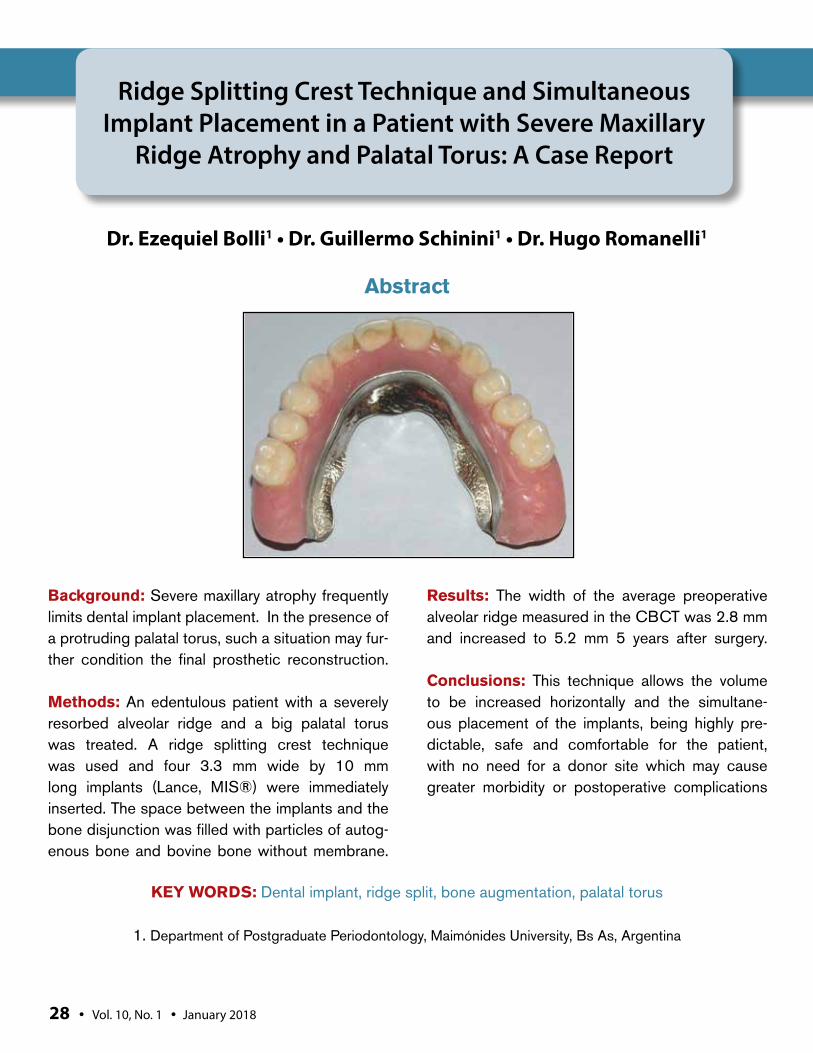
Figure 12: Clinical aspect after treatment. Two separate bars with ball-attach retention system were installed on each side of the maxilla.
Figure 13: Final prosthesis.
Figure 14: Postoperative CBCT after 5 years.
Bolli et al
The Journal of Implant & Advanced Clinical Dentistry • 35
son with the traditional techniques (GBR), since it does not require the maturation of the new regenerated bone for implant placement, thus decreasing morbidity by avoiding a second donor site. However, it can augment only the bucco-lingual dimension of the alveolar ridge and it may not be a suitable option if ridge vertical augmen-tation was necessary. Moreover, various studies have shown that immediate implant placement after ridge splitting crest technique in atrophic maxillary ridges present a survival rate similar to the implants placed in the native bone and good results in the long term.13,14 Numerous reports have shown ridge width augmentation by means of bone disjunction in atrophic jaws using Piezo-surgery, osteotomes, chisels or screw expand-ers or tapered implants.14-21 Chiapasco et al.18 reported an average augmentation of 4 mm (rang-ing 2 to 5) in edentulous ridges after 20 months; Zahran et al.19 reported an augmentation of 2.93 mm after 6 months; and Bassetti et al.20 described
a gain of 4.7 mm after 27 months. In this clini-cal report, the alveolar ridge average width aug-mented 2.4 mm. A recent systematic review indicated an implant survival rate of over 96% using this surgical technique and an increase in average bone width of 3.19 ± 1.19 mm.22
CONCLUSIONS Finally, the Split-crest technique with immedi-ate implant placement in severely resorbed upper maxilla may be considered a reliable option, and a one-stage alternative that is safe and less invasive than the conventional meth-ods of horizontal bone regeneration for atro-phic maxilla with palatal torus presence. l
Correspondence:Dr Guillermo SchininiRioja 2625 Rosario, [email protected]
DisclosureThe author reports no conflicts of interest with anything in this article.
References1. Branemark, P.-I., Hansson, B.O.,
Adell, R., Breine,U., Lindstrom, J., Hallen, O. & Ohman, A. Osseointegrated implants in the treatment of the edentulous jaw. Experience from a 10-year period. Scandinavian Journal of Plastic Reconstructive Surgery 1977,16: 1–132.
2. Landa J. The Torus Palatinus and its management in full denture construction. J Prosthet Dent. 1951 May;1(3):236-43.
3. Tallgren A. The continuing reduction of the residual alveolar ridges in complete denture wearers: a mixed-longitudinal study covering 25 years. J Prosthet Dent 1972;27:120-132
4. Milinkovic I, Cordaro L. Are there specific indications for the different alveolar bone augmentation procedures for implant placement? A systematic review. Int J Oral Maxillofac Surg 2014;43:606–625.
5. Hammerle CH, Jung RE. Bone augmentation by means of barrier membranes. Periodontology 2000 2003;33:36–53.
6. Fiorellini, J.P. & Nevins, M.L. Localized ridge augmentation/preservation. A systematic review. Annals of Periodontology 2003, 8: 321–327.
7. Simion M, Baldoni M, Zaffe D. Jawbone enlargement using immediate implant placement associated with a split-crest technique and guided tissue regeneration. Int J Perio Rest Dent 1992, 12: 462–473
8. Scipioni A, Bruschi GB, Calesini G. The edentulous ridge expansion technique: histologic and ultrastructural study of 20 clinical cases. Int J Perio Rest Dent 1994, 14: 451–459
9. Vercelloti T. Piezoelectric surgery in Implantology: a case report of a new piezoelectric ridge expansion technique. Int Journal of Perio & Rest Dent 2000;20:359-365
10. Pietrokovski J, Massler M. Alveolar ridge resorption following tooth extraction. J Prosthet Dent 1967;17:21–27.
11. Al Quran F, Al Dwairi Z. Torus Palatinus and Torus Mandibularis in edentulous patients. The journal of Contemporary Dental Practice 2006, 7,2:1-8
12. Ella B, Laurentjoye M, Sedarat C, Coutant JC, Masson E, Rouas A. Mandibular ridge expansion using a horizontal bone-splitting technique and synthetic bone substitute: An alternative to bone block grafting? Int J Oral Maxillofac Implants 2014;29:135–140.
13. Garcez Filho J, Tolentino L, Sukekava F, Seabra M, Cesar Neto JB, Araujo MG. Long Term outcomes from implants installed by using split crest technique in posterior maxillae: 10 Years of follow up. Clin Oral Impl Res 2015;26:326-331
14. Blus C, Szmukler Moncler S. Split-crest and immediate implant placement with ultrasonic bone surgery: a 3 year life table analysis with 230 treated sites. Clin Oral Impl Res 2006;17:700-707
15. Demetriades N, Park J, Laskarides C. Alternative bone expansion technique for implant placement in atrophic edentulous maxilla and mandible. Journal of Oral Implantology 2011; 37: 463–471.
16. Gonzalez Garcia, Monje A, Moreno C. Alveolar split osteotomy for the treatment of the severe narrow ridge maxillary atrophy: a modified technique. Int J Oral Maxillofac Surg 2011;40:57-64
17. Calvo Guirado J, Saez Yugguero MR, Carrion del Valle MJ, Pardo Zamora G. A maxillary ridge splitting technique followed by immediate placement of implants: A case Report. Implant Dentistry 2005;14:14-20
18. Chiapasco M, Ferrini F, Casentini P, Accardi S, Zaniboni M: Dental implants placed in expanded narrow edentulous ridges with the extension crest device. A 1-3-year multicenter follow-up study. Clin Oral Impl Res 2006; 17: 265–72.
19. Zahran A, Mostafa B, Hanafy A, Darhous M. A Modified Split-Crest Technique using Piezoelectric Surgery and Immediate Implant Placement in the Atrophic Maxilla. The Journal of Implant & Advanced Clinical Dentistry 2016;8:36-44
20. Bassetti R, Bassetti M, Mericske-Stern R, Enkling N. Piezoelectric alveolar ridge-splitting technique with simultaneous implant placement: a cohort study with 2-year radiographic results. Int J Oral Maxillofac Implants 2013;28:1570-80.
21. Holtzclaw DJ, Toscano NJ, Rosen PS.Reconstruction of posterior mandibular alveolar ridge deficiencies with the piezoelectric hinge-assisted ridge split technique: a retrospective observational report. J Periodontol. 2010;81(11):1580-6.
22. Elnayef B, Monje A, Lin GH, Gargallo-Albiol J, Chan HL, Wang HL, Hernández-Alfaro F. Alveolar ridge split on horizontal bone augmentation: a systematic review. Int J Oral Maxillofac Implants. 2015 30(3):596-606.
Bolli et al
Holtzclaw et al
Background: While smile analysis and design has been routinely used by cosmetic dentists, prosthodontists, and orthodontists to help plan and execute treatment, they are not typically uti-lized by dental implant surgeons. Because of this, a breakdown in communications between the lab, surgeon, and restorative dentist can sometimes lead to less than optimal final results for full arch immediately loaded dental implant cases. Utilization of a standardized and sys-tematic means of smile analysis and design may eliminate many of these issues as all members of the treatment team will be utilizing the same thought process. The current article describes the DIAsmile™ smile analysis and design proto-col which was developed by the authors over the course of treating and restoring 1,000+ full arch immediately loaded dental implant cases.
Methods: The DIAsmile™ smile analysis and design process was developed over many years using a variety of information including a number of articles from PUBMED and Google Scholar searches, facial analysis of 200 celebrity pho-tos, and the authors’ personal experiences with full arch dental implant treatment and resto-ration. The authors now routinely employ the
DIAsmile™ protocol on all full arch immediately loaded dental implant cases and present a Case Report to show a sample of the process.
Results: Articles regarding smile analysis and design are generally consistent in their rec-ommendations, although some minor varia-tions do exist. In utilizing this information to analyze 200 celebrity smiles, patterns were identified for what is considered by many to be an “ideal” smile. These patterns are dis-cussed in this paper and were used in the establishment of the DIAsmile™ smile analy-sis and design protocol. The Case Report in this paper documents use of the DIAsmile™ protocol and shows an aesthetically pleas-ing final outcome that retains solid function. Conclusion: The DIAsmile™ smile analy-sis and design protocol provides a systematic and standardized manner in which the smile of a patient can be analyzed pre-surgically and an aesthetic restoration planned. This pro-cess helps to ensure consistent thought pro-cesses amongst all members of the full arch treatment team and improves the chances for predictably aesthetic final outcomes.
The DIAsmile™ Smile Analysis and Design Protocol for Full Arch Immediately Loaded Implant Dentistry
Dan Holtzclaw, DDS, MS, DABP, DICIO1 • Juan Gonzalez, DMD, DABOMS2 David Malave, DMD, DABOMS2
1. CEO, DIA Dental Implant Centers, LTD.2. Chief Surgeon, DIA Dental Implant Center of Austin, Texas
3. Chief Surgeon, DIA Dental Implant Center of San Antonio, Texas
Abstract
KEY WORDS: Dental implants, smile analysis, smile design, prosthetics
36 • Vol. 10, No. 1 • January 2018
Holtzclaw et al
The Journal of Implant & Advanced Clinical Dentistry • 37
Holtzclaw et al
INTRODUCTIONSmile analysis and design has long been used by prosthodontists and cosmetic dentists for the aesthetic fabrication of full mouth rehabili-tations.1-14 Orthodontists have also used smile analysis and design to plan and finalize orthodon-tic tooth movement.15-17 Recently, full arch imme-diately loaded implant dentistry has become a widely accepted protocol18-40 and this treatment heavily relies on pre-surgical smile analysis and design for the fabrication of both the transitional and final restorations. Typically, full arch immedi-ately loaded dental implant treatment such as the All-On-4™, NeoArch™, ProArch™, and TeethX-press™ protocols have relied on a team approach with a surgical provider performing the place-ment of dental implants/abutments while a sepa-rate restorative provider performs the restorative phase. In some cases, a lack of communication between the laboratory, the surgical provider, and the restorative provider results in implant/abut-ment positioning that may not always be condu-cive to a harmonious aesthetic restorative result. Considering this, a better understanding of smile analysis and design principles on the part of the surgical team would allow for improved dental implant/abutment placement when performing non-computer-guided procedures. The authors of this paper have both performed and restored more than 1,000 cases of full arch immediately loaded implant dentistry. By performing both the surgery and the commensurate accompa-nying restorations, valuable insight has been gained regarding dental implant/abutment posi-tioning and how they affect both the form and function of the restorative phase. In the current paper, the authors discuss the smile analysis and design principles they use for the planning of the
restorative phase of full arch immediately loaded dental implant procedures. Collectively, these analysis and design principles have been bun-dled into a process the authors call DIAsmile™.
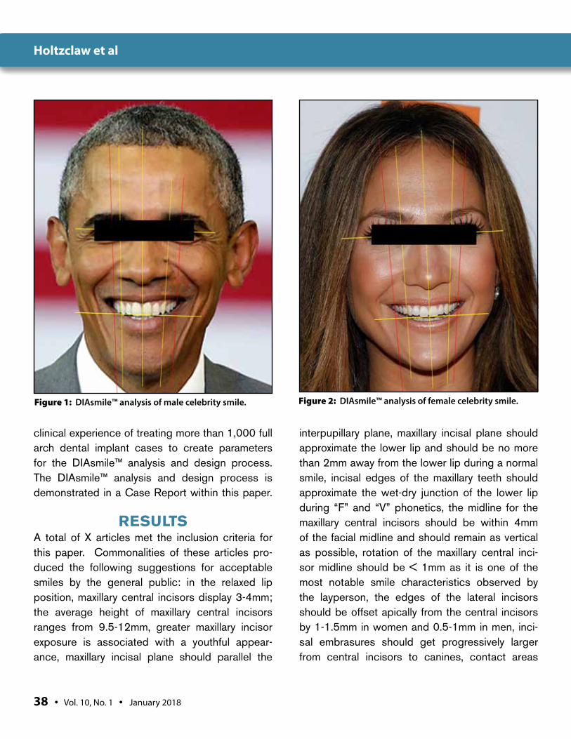
MATERIALS AND METHODSThe DIAsmile™ analysis and design process was developed over many years using a variety of infor-mation. First, a PUBMED database and a sub-sequent Google Scholar search were performed using the following keywords: smile design, smile analysis, dental prosthetic design, and orthodon-tic smile analysis. Of the results returned from this search, only those articles which pertained to external smile characteristics in adults were selected. Second, publicly available photos for 200 celebrities were obtained from Google searches on the internet. Acceptable celebrity photos included only those in which the celeb-rity was smiling and directly facing the camera. A total of 100 male and 100 female celebrities were obtained. Each photo was then inserted into a computer application (Microsoft Powerpoint) and applied to a grid with 0.042 inch gridline spacing. The following parameters were then evaluated by tracing analysis: maxillary incisal plane parallelism to the interpupillary plane; maxillary central incisor midline plane relationship to the chin midline, max-illary central incisor midline plane relationship to the nasal midline, maxillary canine-to-canine width relationship to the width of the nose, buccal cor-ridor relationship to the pupils of the eye, maxillary incisal plane relationship to the body of the lower lip. Celebrity photos were analyzed for smile char-acteristics (Figures 1, 2) because, in the authors’ experience, most patients tend to request smiles that mimic those of particular celebrities. This information was then combined with the authors’
38 • Vol. 10, No. 1 • January 2018
Holtzclaw et al
clinical experience of treating more than 1,000 full arch dental implant cases to create parameters for the DIAsmile™ analysis and design process. The DIAsmile™ analysis and design process is demonstrated in a Case Report within this paper.
RESULTSA total of X articles met the inclusion criteria for this paper. Commonalities of these articles pro-duced the following suggestions for acceptable smiles by the general public: in the relaxed lip position, maxillary central incisors display 3-4mm; the average height of maxillary central incisors ranges from 9.5-12mm, greater maxillary incisor exposure is associated with a youthful appear-ance, maxillary incisal plane should parallel the
interpupillary plane, maxillary incisal plane should approximate the lower lip and should be no more than 2mm away from the lower lip during a normal smile, incisal edges of the maxillary teeth should approximate the wet-dry junction of the lower lip during “F” and “V” phonetics, the midline for the maxillary central incisors should be within 4mm of the facial midline and should remain as vertical as possible, rotation of the maxillary central inci-sor midline should be < 1mm as it is one of the most notable smile characteristics observed by the layperson, the edges of the lateral incisors should be offset apically from the central incisors by 1-1.5mm in women and 0.5-1mm in men, inci-sal embrasures should get progressively larger from central incisors to canines, contact areas
Figure 2: DIAsmile™ analysis of female celebrity smile.Figure 1: DIAsmile™ analysis of male celebrity smile.
The Journal of Implant & Advanced Clinical Dentistry • 39
Holtzclaw et al
between central incisors should approximate 50% the length of the central incisors, contact area between the central incisor and lateral incisor should be 40% of the length of the central incisor, contact area between the lateral incisor and the canine should be 30% of the length of the max-illary central incisor, axial inclination of the maxil-lary teeth should be medially directed, diastemas should be avoided, gingival display during smiling should range from 0-3mm, if gingival tissue is dis-played, the gingival margins of the maxillary cen-tral incisors, lateral incisors, and canines should either be equal or within 1mm of each other (lat-eral incisors being 1mm shorter than the central incisor and canine if chosen to be offset), buccal corridor space should be moderate as too much buccal corridor space gives the appearance of an “empty” smile and too little or no buccal corridor space gives the appearance of a “toothy” or “full” smile, teeth forming the buccal corridor should have a slight medially directed axial inclination and should avoid a flared appearance. In general, the
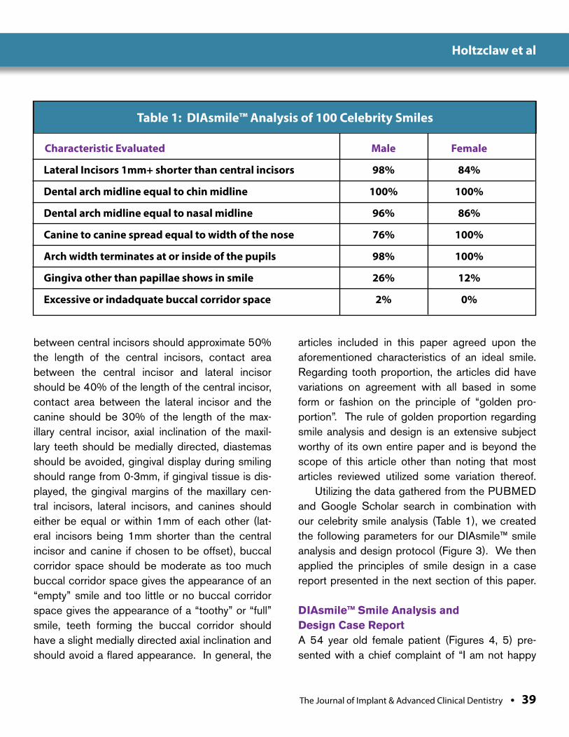
articles included in this paper agreed upon the aforementioned characteristics of an ideal smile. Regarding tooth proportion, the articles did have variations on agreement with all based in some form or fashion on the principle of “golden pro-portion”. The rule of golden proportion regarding smile analysis and design is an extensive subject worthy of its own entire paper and is beyond the scope of this article other than noting that most articles reviewed utilized some variation thereof.
Utilizing the data gathered from the PUBMED and Google Scholar search in combination with our celebrity smile analysis (Table 1), we created the following parameters for our DIAsmile™ smile analysis and design protocol (Figure 3). We then applied the principles of smile design in a case report presented in the next section of this paper.
DIAsmile™ Smile Analysis and Design Case Report A 54 year old female patient (Figures 4, 5) pre-sented with a chief complaint of “I am not happy
Table 1: DIAsmile™ Analysis of 100 Celebrity Smiles
Characteristic Evaluated Male Female
Lateral Incisors 1mm+ shorter than central incisors 98% 84%
Dental arch midline equal to chin midline 100% 100%
Dental arch midline equal to nasal midline 96% 86%
Canine to canine spread equal to width of the nose 76% 100%
Arch width terminates at or inside of the pupils 98% 100%
Gingiva other than papillae shows in smile 26% 12%
Excessive or indadquate buccal corridor space 2% 0%
40 • Vol. 10, No. 1 • January 2018
Holtzclaw et al
with my upper teeth.” The patient had a history of orthodontic treatment during which teeth 1, 5, 12, 16, 17, 21, 28, and 32 were removed. Specifi-cally concerning the maxilla, teeth 8, 14, and 15 were also missing. Carious lesions were noted on teeth 2, 3, 7, 8, 10, and 12. Teeth 3 and 8 dis-played apical radiolucencies and were tender to palpation. Probing depths in the maxilla ranged from 2-6mm with localized bleeding upon prob-ing. A class 2 furcation was noted at the distal of tooth #3, grade 2 mobility was noted on teeth 2, 3, 4, 7, 8, 11, and 12, while class 3 mobility was noted on tooth 10. The patient wore a temporary removable prosthesis to replace missing tooth #9. The mandibular teeth displayed probing depths of 2-4mm with localized bleeding upon probing and
generalized mobility of 0-1 on all teeth. Multiple treatment options regarding the maxilla were pre-sented to the patient with the patient ultimately electing to proceed with immediately loaded full arch dental implant treatment of the maxillary arch. DIAsmile™ analysis of the patient’s existing smile was performed (Figure 6) and the results were discussed with the patient. The patient expressed desire for a “fuller” smile, different tooth shape, whiter teeth, and a final smile that did not appear “fake”. The surgical process was carried out in the standard fashion and a total of 5 dental implants (Neodent CM Drive, Neodent) were used to support an immediately loaded fixed transitional prosthesis. After 4 months of heal-ing, the transitional prosthesis was removed and
Figure 3: DIAsmile™ principles
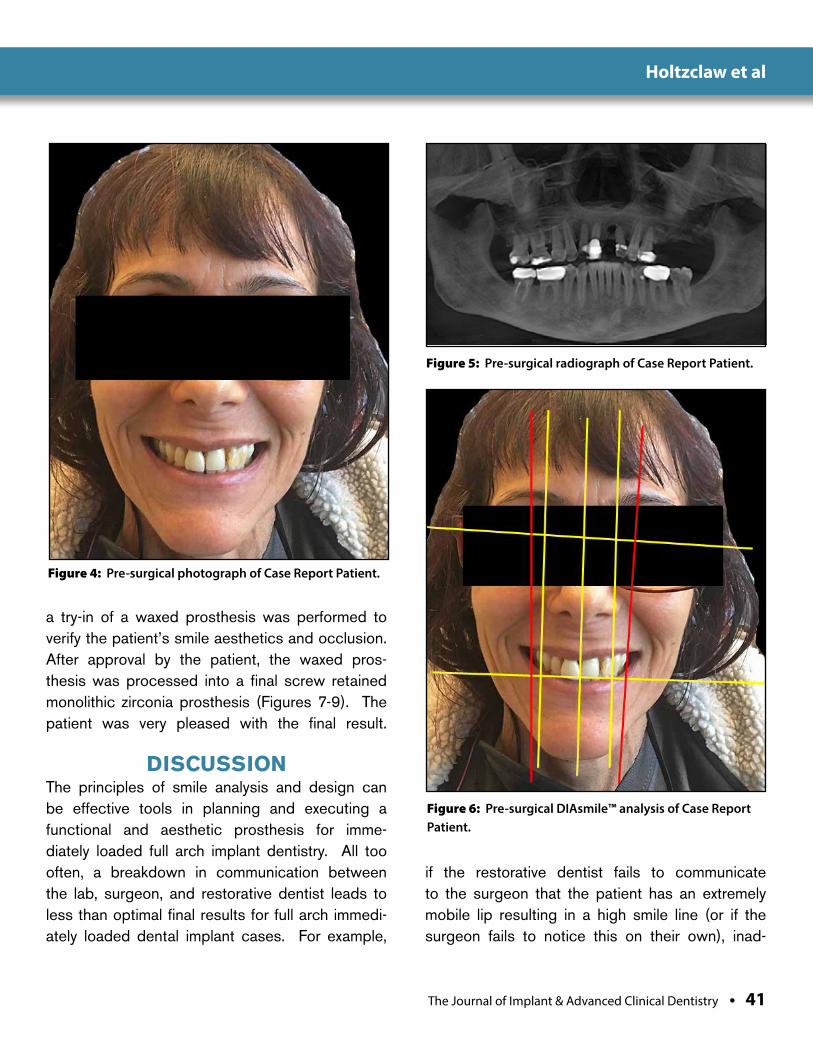
The Journal of Implant & Advanced Clinical Dentistry • 41
Holtzclaw et al
Figure 4: Pre-surgical photograph of Case Report Patient.
Figure 5: Pre-surgical radiograph of Case Report Patient.
a try-in of a waxed prosthesis was performed to verify the patient’s smile aesthetics and occlusion. After approval by the patient, the waxed pros-thesis was processed into a final screw retained monolithic zirconia prosthesis (Figures 7-9). The patient was very pleased with the final result.
DISCUSSION The principles of smile analysis and design can be effective tools in planning and executing a functional and aesthetic prosthesis for imme-diately loaded full arch implant dentistry. All too often, a breakdown in communication between the lab, surgeon, and restorative dentist leads to less than optimal final results for full arch immedi-ately loaded dental implant cases. For example,
if the restorative dentist fails to communicate to the surgeon that the patient has an extremely mobile lip resulting in a high smile line (or if the surgeon fails to notice this on their own), inad-
Figure 6: Pre-surgical DIAsmile™ analysis of Case Report Patient.
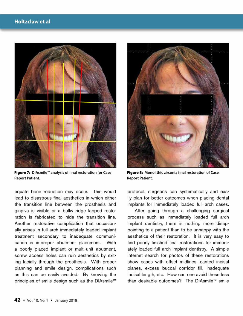
42 • Vol. 10, No. 1 • January 2018
Holtzclaw et al
Figure 7: DIAsmile™ analysis of final restoration for Case Report Patient.
Figure 8: Monolithic zirconia final restoration of Case Report Patient.
equate bone reduction may occur. This would lead to disastrous final aesthetics in which either the transition line between the prosthesis and gingiva is visible or a bulky ridge lapped resto-ration is fabricated to hide the transition line. Another restorative complication that occasion-ally arises in full arch immediately loaded implant treatment secondary to inadequate communi-cation is improper abutment placement. With a poorly placed implant or multi-unit abutment, screw access holes can ruin aesthetics by exit-ing facially through the prosthesis. With proper planning and smile design, complications such as this can be easily avoided. By knowing the principles of smile design such as the DIAsmile™
protocol, surgeons can systematically and eas-ily plan for better outcomes when placing dental implants for immediately loaded full arch cases.
After going through a challenging surgical process such as immediately loaded full arch implant dentistry, there is nothing more disap-pointing to a patient than to be unhappy with the aesthetics of their restoration. It is very easy to find poorly finished final restorations for immedi-ately loaded full arch implant dentistry. A simple internet search for photos of these restorations show cases with offset midlines, canted incisal planes, excess buccal corridor fill, inadequate incisal length, etc. How can one avoid these less than desirable outcomes? The DIAsmile™ smile
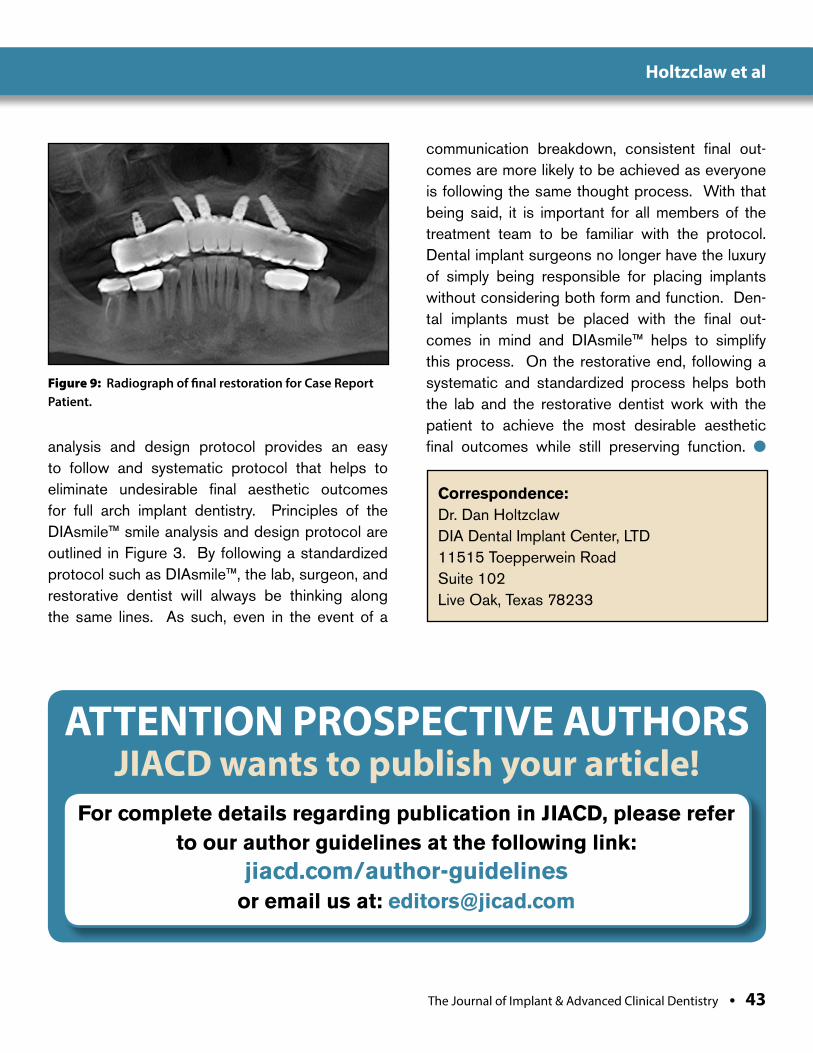
The Journal of Implant & Advanced Clinical Dentistry • 43
Holtzclaw et al
Figure 9: Radiograph of final restoration for Case Report Patient.
analysis and design protocol provides an easy to follow and systematic protocol that helps to eliminate undesirable final aesthetic outcomes for full arch implant dentistry. Principles of the DIAsmile™ smile analysis and design protocol are outlined in Figure 3. By following a standardized protocol such as DIAsmile™, the lab, surgeon, and restorative dentist will always be thinking along the same lines. As such, even in the event of a
communication breakdown, consistent final out-comes are more likely to be achieved as everyone is following the same thought process. With that being said, it is important for all members of the treatment team to be familiar with the protocol. Dental implant surgeons no longer have the luxury of simply being responsible for placing implants without considering both form and function. Den-tal implants must be placed with the final out-comes in mind and DIAsmile™ helps to simplify this process. On the restorative end, following a systematic and standardized process helps both the lab and the restorative dentist work with the patient to achieve the most desirable aesthetic final outcomes while still preserving function. l
Correspondence:Dr. Dan HoltzclawDIA Dental Implant Center, LTD11515 Toepperwein RoadSuite 102Live Oak, Texas 78233
ATTENTION PROSPECTIVE AUTHORSJIACD wants to publish your article!
For complete details regarding publication in JIACD, please refer to our author guidelines at the following link:
jiacd.com/author-guidelines or email us at: [email protected]
44 • Vol. 10, No. 1 • January 2018
Holtzclaw et al
DisclosureDIAsmile™ is a registered trademark of DIA Dental Implant Centers, LTD.
References1. Kirtley G. The Art of a Beautiful Smile. J Cosmetic
Dent 2008;24(3):122-131.
2. Lombardi R. The Principles of Visual Perception and Their Clinical Application to Denture Esthetics. J Prosthet Dent 1973;29:358-382.
3. Ward D. Proportional Smile Design Using the Recurring Esthetic Dental Proportion. Dent Clin North Am 2001;45:143-154.
4. Mistry S. Principles of Smile Design Demystified. J Cosmetic Dent 2012;28(2):116-124.
5. McLaren A, Rifkin R. Macroesthetics: Facial and Dentofacial Analysis. Calif Dent Assoc 2002;30(11):839-846.
6. Morley J, Eubank J. Macroesthetic Elements of Smile Design. J Am Dent Assoc 2001;132(1):39-45.
7. Sulikowski A, Yoshida A. Three Dimensional Management of Dental Proportions: A New Esthetic Prinicple “The Frame of Reference”. QDT 2002;25:8-20.
8. McLaren E, Culp L. Smile Analysis: The Photoshop Design Technique: Part 1. J Cosmetic Dent 2013;29(1):94-108.
9. McLaren E, Tran Cao P. Smile Analysis and Esthetic Design “In the Zone”. Inside Dent 2009;5(7):46-48.
10. Davis N. Smile Design. Dent Clin North Am 2007;51:299-318.
11. Preston J. The Gold Proprtion Revisited. J Esthetic Dent 1993;5:247-251.
12. Bidra A. Three Dimensional Esthetic Analysis in Treatment Planning for Implant Supported Fixed Prosthesis in the Edentulous Maxilla: Review of the Esthetics Literature. J Esthetic Restor Dent 2011;23(4):219-236.
13. Coachman C, Calamita M, Sesma N. Dynamic Documentation of the Smile and the 2D/3D Digital Smile Design Process. Int J Periodont Res Dent 2017;37(2):183-193.
14. LeSage B, Dalloca L. Approaches to Smile Design: Mathematical to Artistic Interpretation. J Cosmetic Dent 2012;28(1):126-147.
15. Machado A. 10 Commandments of Smile Esthetics. J Orthod 2014;19(4):136-157.
16. Machado A, Moon W, Gandini L. Influence of Maxillary Incisor Edge Asymmetries on the Perception of Smile Esthetics Among Orthodontists and Laypersons. Am J Orthod Dentofacial Orthop 2013;143(5):658-664.
17. Ackerman M, Ackerman J. Smile Analysis and Design in the Digital Era. JCO 2002;4:221-236.
18. Maló P, Araújo Nobre MD, Lopes A, Rodrigues R. Double Full-Arch Versus Single Full-Arch, Four Implant-Supported Rehabilitations: A Retrospective, 5-Year Cohort Study. J Prosthodont 2014;Oct 1
19. Maló P, Rangert B, Nobre M. “All-on-Four” immediate-function concept with Brånemark System implants for completely edentulous mandibles: a retrospective clinical study. Clin Implant Dent Relat Res 2003;5:2-9.
20. Krekmanov L, Kahn M, Rangert B, Lindström H. Tilting of posterior mandibular and maxillary implants for improved prosthesis support. Int J Oral Maxillofac Implants 2000;15:405-14.
21. Butura CC, Galindo DF, Jensen OT. Mandibular all-on-four therapy using angled implants: a three-year clinical study of 857 implants in 219 jaws. Dent Clin North Am 2011;55:795-811.
22. Maló P, Rangert B, Nobre M. All-on-4 immediate-function concept with Brånemark System implants for completely edentulous maxillae: a 1-year retrospective clinical study. Clin Implant Dent Relat Res 2005;7:88-94.
23. Balshi TJ, Wolfinger GJ, Slauch RW, Balshi SF. A retrospective analysis of 800 Brånemark System implants following the All-on-Four™ protocol. J Prosthodont 2014;23:83-88.
24. Jensen OT, Adams MW. All-on-4 treatment of highly atrophic mandible with mandibular V-4: report of 2 cases. J Oral Maxillofac Surg 2009;67:1503-9.
25. Acocella A, Ercoli C, Geminiani A, Feng C, Billi M, Acocella G, Giannini D, Sacco R. Clinical evaluation of immediate loading of electroeroded screw-retained titanium fixed prostheses supported by tilted implant: a multicenter retrospective study. Clin Implant Dent Relat Res 2012;14:98-108.
26. Chu P. A case study: The all-on-4 treatment concept using Biohorizons tapered internal implants. Clin Pract Oral Implantol 2010;1:28-36.
27. Alves CC, Correia AR, Neves M. Immediate implants and immediate loading in periodontally compromised patients-a 3-year prospective clinical study. Int J Periodontics Restorative Dent 2010;30:447-55.
28. Lazzara RJ, Testori T, Meltzer A, Misch C, Porter S, del Castillo R, Goené RJ. Immediate Occlusal Loading (IOL) of dental implants: predictable results through DIEM guidelines. Pract Proced Aesthet Dent 2004;16:3-15.
29. Capelli M, Zuffetti F, Del Fabbro M, Testori T. Immediate rehabilitation of the completely edentulous jaw with fixed prostheses supported by either upright or tilted implants: a multicenter clinical study. Int J Oral Maxillofac Implants 2007;22:639-44.
30. Testori T, Del Fabbro M, Capelli M, Zuffetti F, Francetti L, Weinstein RL. Immediate occlusal loading and tilted implants for the rehabilitation of the atrophic edentulous maxilla: 1-year interim results of a multicenter prospective study. Clin Oral Implants Res 2008;19:227-32.
31. Boyse B, Sullivan S. Implant placement and immediate provisional restoration of edentulous arches: A case presentation. J Implant Reconstruc Dent 2011;2:1-5.
32. Pomares C. A retrospective clinical study of edentulous patients rehabilitated according to the ‘all on four’ or the ‘all on six’ immediate function concept. Eur J Oral Implantol 2009;2:55-60.
33. Agliardi E, Clericò M, Ciancio P, Massironi D. Immediate loading of full-arch fixed prostheses supported by axial and tilted implants for the treatment of edentulous atrophic mandibles. Quintessence Int 2010;41:285-93.
34. Babbush CA, Kutsko GT, Brokloff J. The all-on-four immediate function treatment concept with NobelActive implants: a retrospective study. J Oral Implantol 2011;37:431-45.
35. Malo P, de Araújo Nobre M, Lopes A, Moss SM, Molina GJ. A longitudinal study of the survival of All-on-4 implants in the mandible with up to 10 years of follow-up. J Am Dent Assoc 2011;142:310-20.
36. Maló P, de Araújo Nobre M, Lopes A, Francischone C, Rigolizzo M. “All-on-4” immediate-function concept for completely edentulous maxillae: a clinical report on the medium (3 years) and long-term (5 years) outcomes. Clin Implant Dent Relat Res 2012;14:139-50.
37. Maló P, de Araújo Nobre M. Partial rehabilitation of the posterior edentulous maxilla using axial and tilted implants in immediate function to avoid bone grafting. Compend Contin Educ Dent 2011;32:136-45.
38. Maló P, Nobre Md, Lopes A. The rehabilitation of completely edentulous maxillae with different degrees of resorption with four or more immediately loaded implants: a 5-year retrospective study and a new classification. Eur J Oral Implantol 2011;4:227-43.
39. Malo P, Nobre Mde A, Lopes A. Immediate rehabilitation of completely edentulous arches with a four-implant prosthesis concept in difficult conditions: an open cohort study with a mean follow-up of 2 years. Int J Oral Maxillofac Implants 2012;27:1177-90.
40. Agliardi E, Panigatti S, Clericò M, Villa C, Malò P. Immediate rehabilitation of the edentulous jaws with full fixed prostheses supported by four implants: interim results of a single cohort prospective study. Clin Oral Implants Res 2010;21:459-65.

The Journal of Implant & Advanced Clinical Dentistry • XX
Holtzclaw et al Get Social with
@JIACD on twitter
“JIACD dental journal” on LinkedIn
JIACD on FB
The Best Things in Life Are FREE!
Subscribe now to enjoy articles free of charge that will benefit you, the actively practicing dental provider. With each JIACD issue, readers are afforded the opportunity to
assess clinical techniques, cases, literature reviews, and expert commentary that can immediately impact their daily dental practice.
Email notification when new issues are available online.
Start your FREE subscription today at www.jiacd.com
The Journal of Implant & Advanced Clinical Dentistry
Volume 9, No. 4 may/JuNe 2017
Xenograft Socket Preservation
The MIMS Technique for Gingival Grafting
The Journal of Implant & Advanced Clinical Dentistry
Volume 9, No. 2 February 2017
Updated Primer on Amnion-Chorion Allografts
Computer Guided Full Arch Immediately Loaded
Dental Implants
The Journal of Implant & Advanced Clinical Dentistry
Volume 9, No. 6 August 2017
Impacted Canine Replacement
6 Year Multi-Center Study onOsseofuse Dental Implants
The Journal of Implant & Advanced Clinical Dentistry
Volume 9, No. 7 September 2017
Biotype Tissue Change at Second Stage Implant Surgery
Immediate vs. Early Loading of Short Implants