Embed Size (px)
Citation preview
PanasonicLIQI
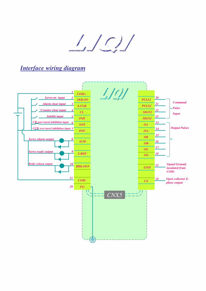
COM+
SER-ON
A-CLR
CL
INH
NOT
POT
ALM
S-RDY
BRK-OFF
FG
Servo-on input
1
2
3
4
5
6
7
Alarm clear input
Counter clear input
Inhibit input
CW over travel inhibition input
CCW over travel inhibition input
COM-
Servo Alarm output
Servo ready output
Brake release output
8
9
10
11
26
20
21
22
23
Command
Pulse
Input
13
14
15
16
17
18
PULS1
PULS2
SIGN1
SIGN2
OA
OA-
OB
OB-
OZ
OZ-
CZOpen collector Z-phase output
CNX5
Output Pulses
Interface wiring diagram
GNDSignal Ground, insulated from COM-
12
19
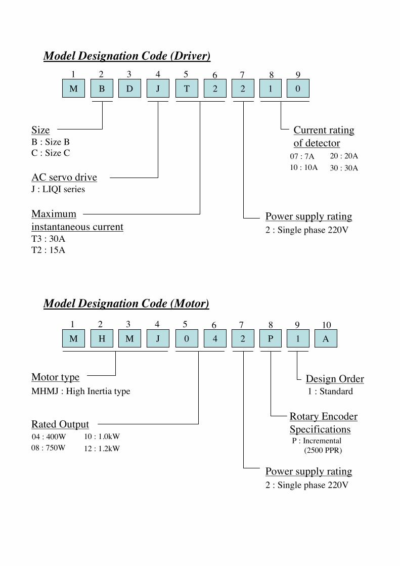
Model Designation Code (Driver)
M B D J T 2 2 1 01 2 3 4 5 6 7 8 9
Size
AC servo driveJ : LIQI series
Maximum instantaneous current
Current rating of detector
07 : 7A10 : 10A
20 : 20A30 : 30A
Power supply rating2 : Single phase 220V
T2 : 15AT3 : 30A
Model Designation Code (Motor)
M H M J 0 4 2 P 11 2 3 4 5 6 7 8 9
Motor type
Rated Output
Power supply rating2 : Single phase 220V
A10
MHMJ : High Inertia type
04 : 400W08 : 750W
10 : 1.0kW12 : 1.2kW
Rotary Encoder SpecificationsP : Incremental
(2500 PPR)
Design Order1 : Standard
B : Size BC : Size C
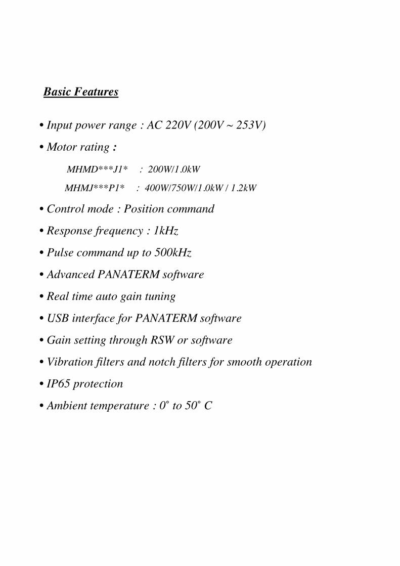
• Input power range : AC 220V (200V ~ 253V)
• Motor rating :
MHMD***J1* 㧦 200W/1.0kW
MHMJ***P1* 㧦 400W/750W/1.0kW / 1.2kW
• Control mode : Position command
• Response frequency : 1kHz
• Pulse command up to 500kHz
• Advanced PANATERM software
• Real time auto gain tuning
• USB interface for PANATERM software
• Gain setting through RSW or software
• Vibration filters and notch filters for smooth operation
• IP65 protection
• Ambient temperature : 0˚ to 50˚ C
Basic Features
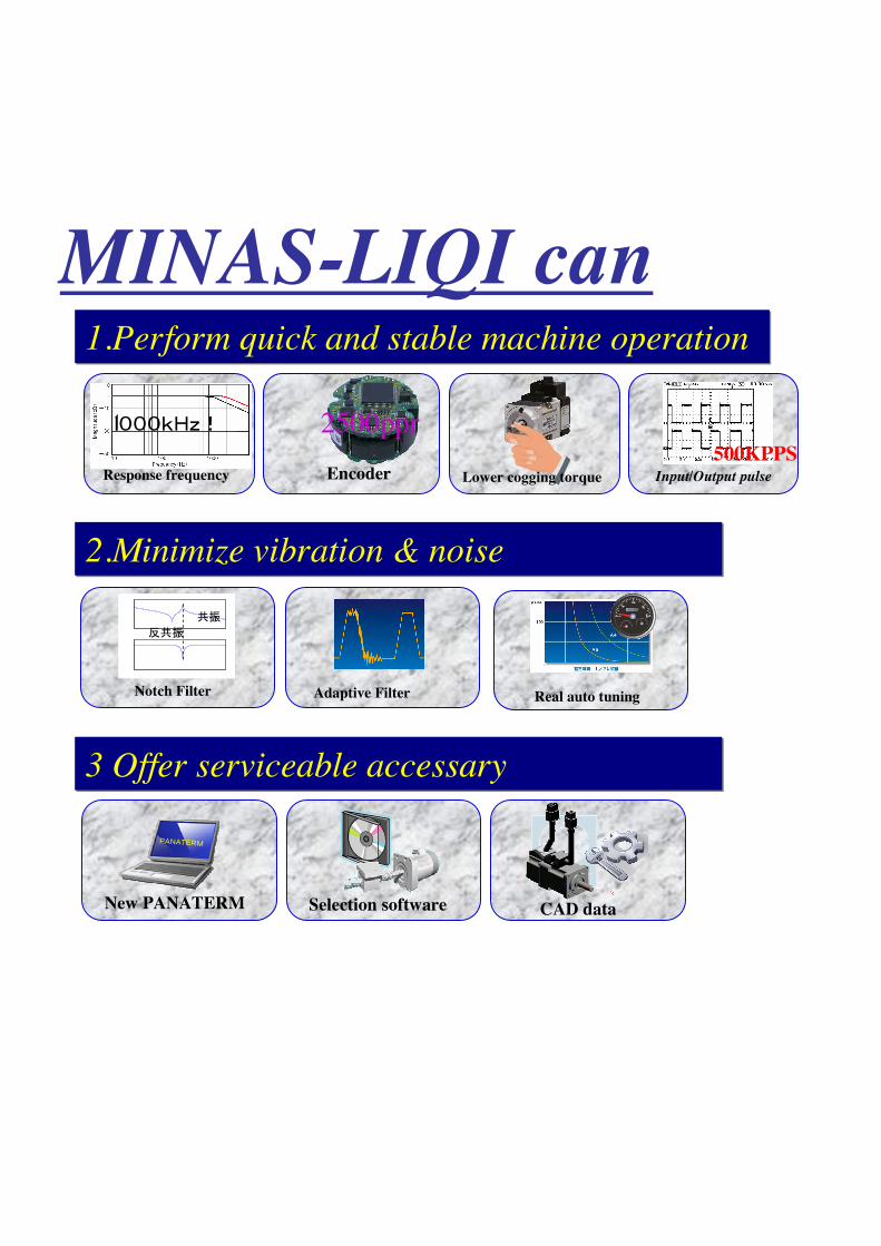
1.Perform quick and stable machine operation 1.Perform quick and stable machine operation
2.Minimize vibration & noise2.Minimize vibration & noise
3 Offer serviceable accessary3 Offer serviceable accessary
MINAS-LIQI can
1䋰䋰䋰䌫䌈䌺䋣
Response frequency
2500pprEncoder Lower cogging torque
ᝄ
ᝄ
Notch Filter Adaptive Filter
500KPPSInput/Output pulse
䌐䌁䌎䌁䌔䌅䌒䌍
New PANATERM Selection software CAD data
Real auto tuning
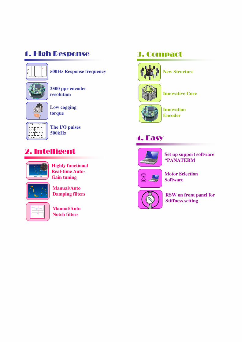
1. High Response
500Hz Response frequency
2500 ppr encoder resolution
Low cogging torque
The I/O pulses 500kHz
2. Intelligent
Highly functional Real-time Auto-Gain tuning
Manual/Auto Damping filters
Manual/Auto Notch filters
3. Compact
New Structure
Innovative Core
Innovation Encoder
4. Easy
Set up support software “PANATERM
Motor Selection Software
RSW on front panel for Stiffness setting
SR-DSV10739 - 2 -
! ! ! Motor Business Unit, Home Appliances Company, Panasonic
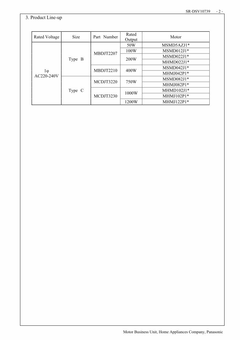
3. Product Line-up
Rated Voltage Size Part NumberRated Output
Motor
50W MSMD5AZJ1*
100W MSMD012J1*
MSMD022J1* MBDJT2207
200W MHMD022J1*
MSMD042J1*
Type B
MBDJT2210 400W MHMJ042P1*
MSMD082J1* MCDJT3220 750W
MHMJ082P1*
MHMD102J1* 1000W
MHMJ102P1*
1! AC220-240V
Type C
MCDJT3230
1200W MHMJ122P1*
SR-DSV10739 - 3 -
! ! ! Motor Business Unit, Home Appliances Company, Panasonic
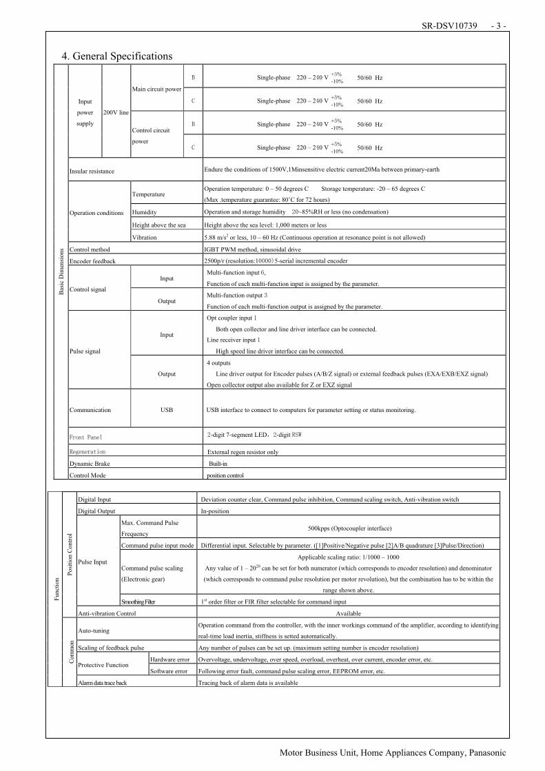
4. General Specifications
Single-phase 220 – 2 0 V+ %
-1 %!50/60 Hz!
Main circuit power
Single-phase 220 – 2 0 V+ %
-1 %!50/60 Hz!
Single-phase 220 – 2 0 V+ %
-1 %!50/60 Hz!
Input
power
supply
200V line
Control circuit
power Single-phase 220 – 2 0 V
+ %
-1 %!50/60 Hz!
Insular resistance Endure the conditions of 1500V,1Minsensitive electric current20Ma between primary-earth
Temperature Operation temperature: 0 – 50 degrees C Storage temperature: -20 – 65 degrees C
(Max .temperature guarantee: 80!C for 72 hours)
Humidity Operation and storage humidity ~85%RH or less (no condensation)
Height above the sea Height above the sea level: 1,000 meters or less
Operation conditions
Vibration 5.88 m/s2 or less, 10 – 60 Hz (Continuous operation at resonance point is not allowed)
Control method IGBT PWM method, sinusoidal drive
Encoder feedback 2500p/r (resolution:1 5-serial incremental encoder
Input Multi-function input ,
Function of each multi-function input is assigned by the parameter. Control signal
Output Multi-function output
Function of each multi-function output is assigned by the parameter.
Input
Opt coupler input
Both open collector and line driver interface can be connected.
Line receiver input
High speed line driver interface can be connected. Pulse signal
Output
4 outputs
Line driver output for Encoder pulses (A/B/Z signal) or external feedback pulses (EXA/EXB/EXZ signal)
Open collector output also available for Z or EXZ signal
Communication USB USB interface to connect to computers for parameter setting or status monitoring.
"#$%&!'(%)* -digit 7-segment LED -digit
+),)%)#(&-$% External regen resistor only
Dynamic Brake Built-in
Bas
ic D
imen
sio
ns
Control Mode position control
Digital Input Deviation counter clear, Command pulse inhibition, Command scaling switch, Anti-vibration switch
Digital Output In-position
Max. Command Pulse
Frequency 500kpps (Optocoupler interface)
Command pulse input mode Differential input. Selectable by parameter. ([1]Positive/Negative pulse [2]A/B quadrature [3]Pulse/Direction)
Command pulse scaling
(Electronic gear)
Applicable scaling ratio: 1/1000 – 1000
Any value of 1 – 2020 can be set for both numerator (which corresponds to encoder resolution) and denominator
(which corresponds to command pulse resolution per motor revolution), but the combination has to be within the
range shown above.
Pulse Input
Smoothing Filter 1st order filter or FIR filter selectable for command input
Po
siti
on
Con
trol
Anti-vibration Control Available
Auto-tuning Operation command from the controller, with the inner workings command of the amplifier, according to identifying
real-time load inertia, stiffness is setted automatically.
Scaling of feedback pulse Any number of pulses can be set up. (maximum setting number is encoder resolution)
Hardware error Overvoltage, undervoltage, over speed, overload, overheat, over current, encoder error, etc. Protective Function
Software error Following error fault, command pulse scaling error, EEPROM error, etc.
Fu
nct
ion
Com
mon
Alarm data trace back Tracing back of alarm data is available
SR-DSV10739 - 4 -
! ! ! Motor Business Unit, Home Appliances Company, Panasonic
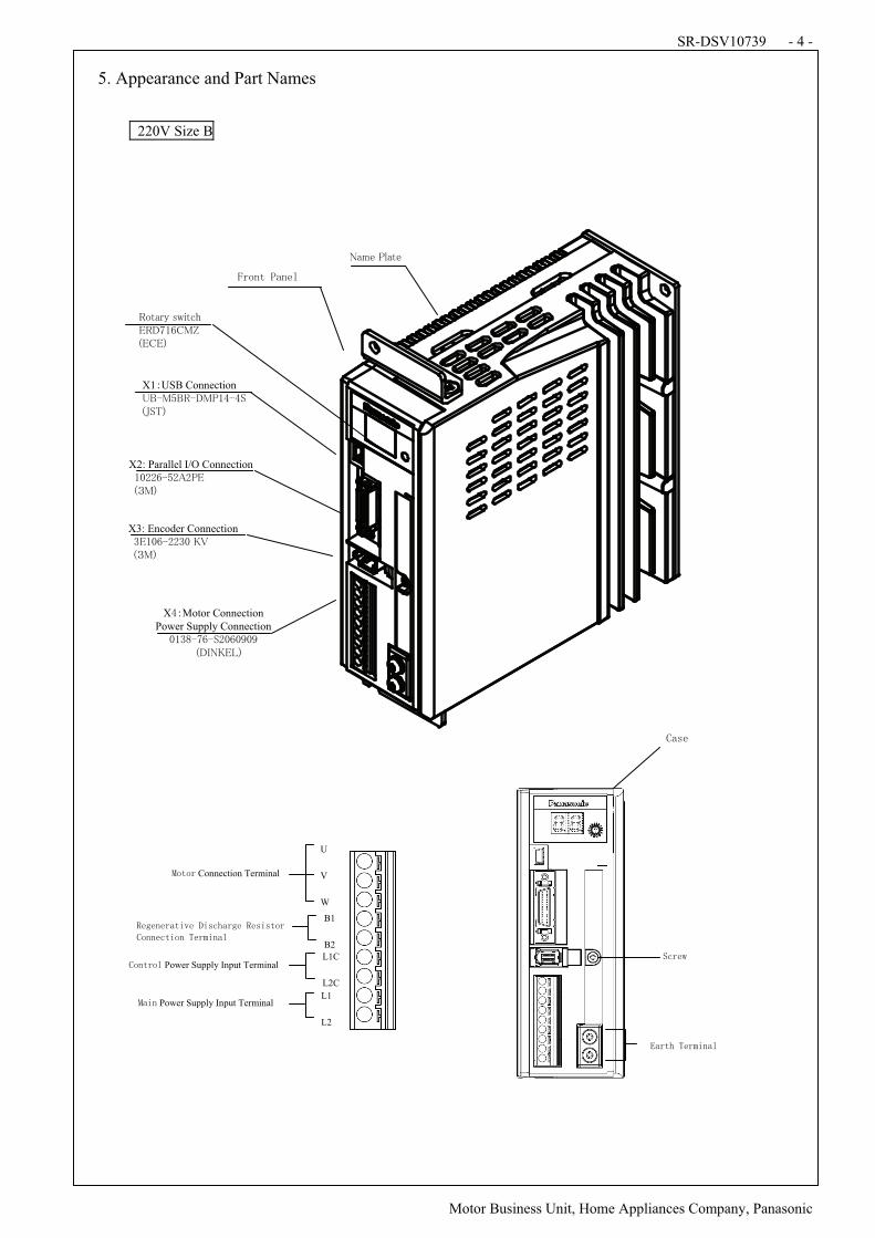
5. Appearance and Part Names
220V Size B
X !Motor Connection Power Supply Connection
"#$%&'(&)*"("+"+,-./01234,
X1!USB Connection 56&7869&.7:#;&;),-<)=4,
X2: Parallel I/O Connection #"**(&8*>*:2, ,-?74,
X3: Encoder Connection $2#"(&**$",1@, ,-?74,
9ABCDE,FGHBIJ,29.'#(K7L, ,-2K24,
0CMN,:OCBN,
,
,
U
V
W
Connection Terminal
B1
B2
L1C
L2C
Power Supply Input Terminal
L1
L2
Power Supply Input Terminal
SR-DSV10739 - 5 -
! ! ! Motor Business Unit, Home Appliances Company, Panasonic
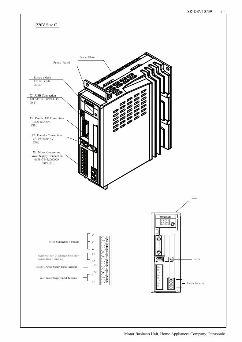
220V Size C
0CMN,:OCBN,
,
X !Motor Connection Power Supply Connection
"#$%&'(&)*"("+"+,-./01234,
X1!USB Connection 56&7869&.7:#;&;),-<)=4,
X2: Parallel I/O Connection #"**(&8*>*:2, ,-?74,
X3: Encoder Connection $2#"(&**$",1@, ,-?74,
9ABCDE,FGHBIJ,29.'#(K7L, ,-2K24,
,
B1
B2
L1
L2
L1C
L2C
U
V
W
Power Supply Input Terminal
Connection Terminal
Power Supply Input Terminal
SR-DSV10739 - 6 -
! ! ! Motor Business Unit, Home Appliances Company, Panasonic
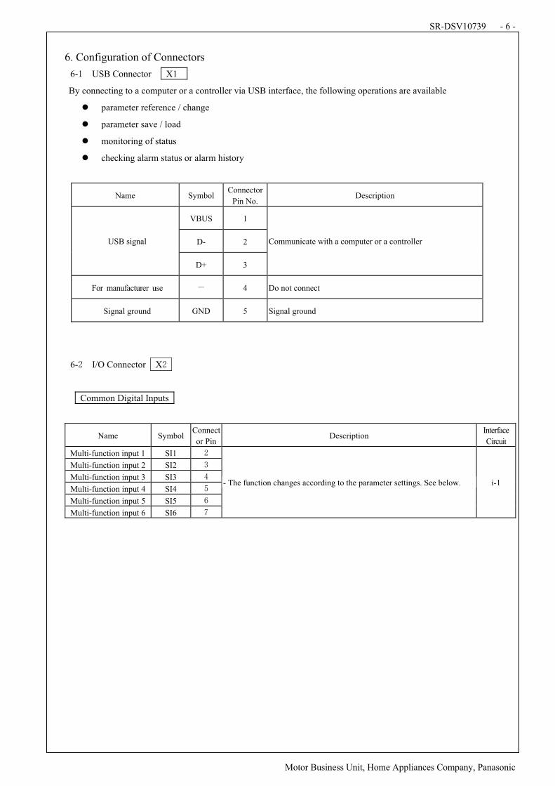
6. Configuration of Connectors
6- USB Connector! X1
By connecting to a computer or a controller via USB interface, the following operations are available
! parameter reference / change
! parameter save / load
! monitoring of status
! checking alarm status or alarm history
!
Name Symbol Connector
Pin No. Description
VBUS 1
D- 2 USB signal
D+ 3
Communicate with a computer or a controller
For manufacturer use . 4 Do not connect
Signal ground GND 5 Signal ground
!
! 6- I/O Connector X
Common Digital Inputs
Name Symbol Connect
or Pin Description
Interface
Circuit
Multi-function input 1 SI1
Multi-function input 2 SI2
Multi-function input 3 SI3
Multi-function input 4 SI4
Multi-function input 5 SI5
Multi-function input 6 SI6
- The function changes according to the parameter settings. See below. i-1
SR-DSV10739 - 7 -
! ! ! Motor Business Unit, Home Appliances Company, Panasonic
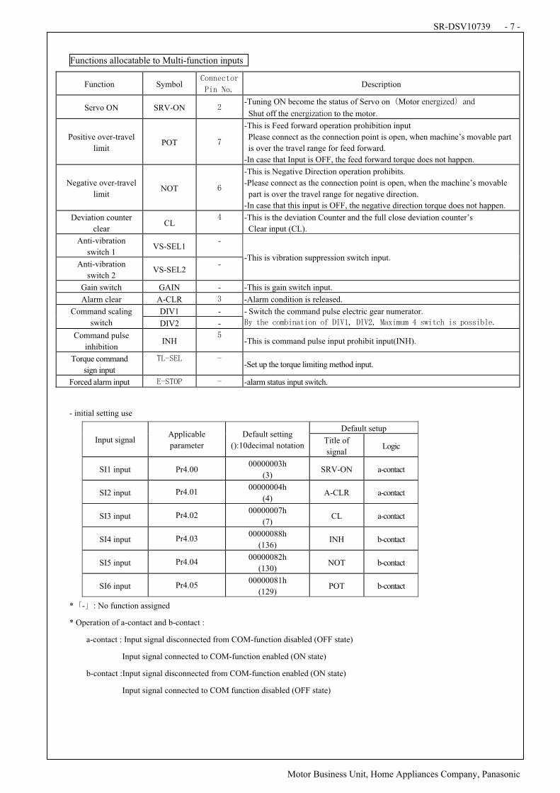
Functions allocatable to Multi-function inputs
Function Symbol !
Description
Servo ON SRV-ON !-Tuning ON become the status of Servo on/Motor energized0and
Shut off the energization to the motor.
Positive over-travel
limit POT !
-This is Feed forward operation prohibition input
Please connect as the connection point is open, when machine’s movable part
is over the travel range for feed forward.
-In case that Input is OFF, the feed forward torque does not happen.
Negative over-travel
limit NOT !
-This is Negative Direction operation prohibits.
-Please connect as the connection point is open, when the machine’s movable
part is over the travel range for negative direction.
-In case that this input is OFF, the negative direction torque does not happen.
Deviation counter
clear CL
-This is the deviation Counter and the full close deviation counter’s
Clear input (CL).
Anti-vibration
switch 1 VS-SEL1
-
Anti-vibration
switch 2 VS-SEL2
--This is vibration suppression switch input.
Gain switch GAIN - -This is gain switch input.
Alarm clear A-CLR -Alarm condition is released.
DIV1 - Command scaling
switch DIV2 -
- Switch the command pulse electric gear numerator.
12!&3)!4$56-%(&-$%!$7!89:;<!89:=<!>(?-5@5!A!BC-&43!-B!D$BB-6*)E
Command pulse
inhibition INH
-This is command pulse input prohibit input(INH).
Torque command
sign input
FGHIJG! H!-Set up the torque limiting method input.
Forced alarm input JHIFK'! H! -alarm status input switch.
- initial setting use
Default setup
Input signal Applicable
parameter
Default setting
():10decimal notationTitle of
signal Logic
SI1 input Pr4.00 00000003h
(3) SRV-ON a-contact
SI2 input Pr4.01 00000004h
(4) A-CLR a-contact
SI3 input Pr4.02 00000007h
(7) CL a-contact
SI4 input Pr4.03 00000088h
(136) INH b-contact
SI5 input Pr4.04 00000082h
(130) NOT b-contact
SI6 input Pr4.05 00000081h
(129) POT b-contact
*L-M: No function assigned
* Operation of a-contact and b-contact :
a-contact : Input signal disconnected from COM-function disabled (OFF state)
Input signal connected to COM-function enabled (ON state)
b-contact :Input signal disconnected from COM-function enabled (ON state)
Input signal connected to COM function disabled (OFF state)
SR-DSV10739 - 8 -
! ! ! Motor Business Unit, Home Appliances Company, Panasonic
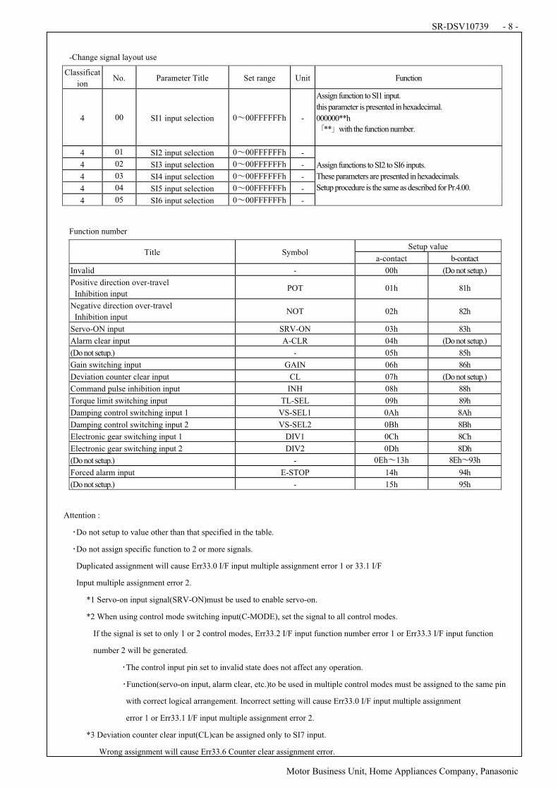
-Change signal layout use
Classificat
ion No. Parameter Title Set range Unit Function
4 00 SI1 input selection 0N00FFFFFFh -
Assign function to SI1 input.
this parameter is presented in hexadecimal.
000000**h
L**Mwith the function number.
4 01 SI2 input selection 0N00FFFFFFh -
4 02 SI3 input selection 0N00FFFFFFh -
4 03 SI4 input selection 0N00FFFFFFh -
4 04 SI5 input selection 0N00FFFFFFh -
4 05 SI6 input selection 0N00FFFFFFh -
Assign functions to SI2 to SI6 inputs.
These parameters are presented in hexadecimals.
Setup procedure is the same as described for Pr.4.00.
Function number
Setup value Title Symbol
a-contact b-contact
Invalid - 00h (Do not setup.)
Positive direction over-travel
Inhibition input POT 01h 81h
Negative direction over-travel
Inhibition input NOT 02h 82h
Servo-ON input SRV-ON 03h 83h
Alarm clear input A-CLR 04h (Do not setup.)
(Do not setup.) - 05h 85h
Gain switching input GAIN 06h 86h
Deviation counter clear input CL 07h (Do not setup.)
Command pulse inhibition input INH 08h 88h
Torque limit switching input TL-SEL 09h 89h
Damping control switching input 1 VS-SEL1 0Ah 8Ah
Damping control switching input 2 VS-SEL2 0Bh 8Bh
Electronic gear switching input 1 DIV1 0Ch 8Ch
Electronic gear switching input 2 DIV2 0Dh 8Dh
(Do not setup.) - 0EhN13h 8EhN93h
Forced alarm input E-STOP 14h 94h
(Do not setup.) - 15h 95h
Attention :
ODo not setup to value other than that specified in the table.
ODo not assign specific function to 2 or more signals.
Duplicated assignment will cause Err33.0 I/F input multiple assignment error 1 or 33.1 I/F
Input multiple assignment error 2.
*1 Servo-on input signal(SRV-ON)must be used to enable servo-on.
*2 When using control mode switching input(C-MODE), set the signal to all control modes.
If the signal is set to only 1 or 2 control modes, Err33.2 I/F input function number error 1 or Err33.3 I/F input function
number 2 will be generated.
OThe control input pin set to invalid state does not affect any operation.
OFunction(servo-on input, alarm clear, etc.)to be used in multiple control modes must be assigned to the same pin
with correct logical arrangement. Incorrect setting will cause Err33.0 I/F input multiple assignment
error 1 or Err33.1 I/F input multiple assignment error 2.
*3 Deviation counter clear input(CL)can be assigned only to SI7 input.
Wrong assignment will cause Err33.6 Counter clear assignment error.
SR-DSV10739 - 9 -
! ! ! Motor Business Unit, Home Appliances Company, Panasonic
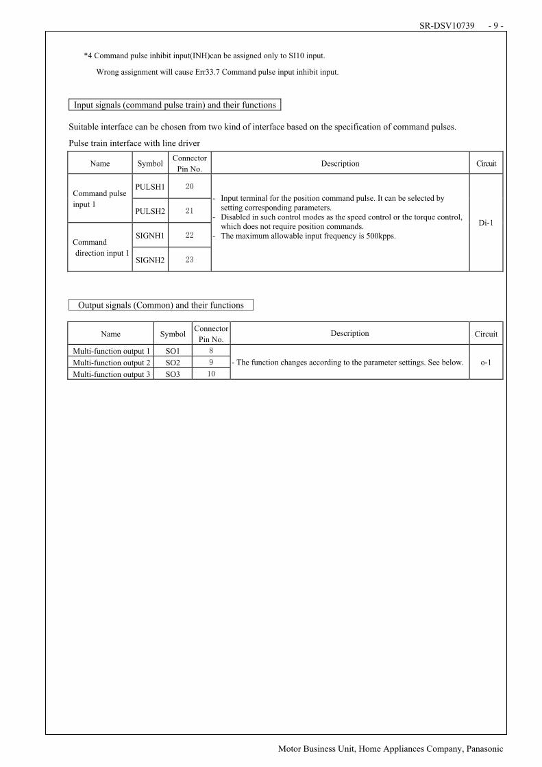
*4 Command pulse inhibit input(INH)can be assigned only to SI10 input.
Wrong assignment will cause Err33.7 Command pulse input inhibit input.
Input signals (command pulse train) and their functions
Suitable interface can be chosen from two kind of interface based on the specification of command pulses.
Pulse train interface with line driver
Name SymbolConnector
Pin No. Description Circuit
PULSH1 Command pulse
input 1 PULSH2
SIGNH1 Command
direction input 1 SIGNH2
- Input terminal for the position command pulse. It can be selected by setting corresponding parameters.
- Disabled in such control modes as the speed control or the torque control, which does not require position commands.
- The maximum allowable input frequency is 500kpps.
Di-
Output signals (Common) and their functions
Name Symbol Connector
Pin No. Description Circuit
Multi-function output 1 SO1
Multi-function output 2 SO2
Multi-function output 3 SO3
- The function changes according to the parameter settings. See below. o-1
SR-DSV10739 - 10 -
! ! ! Motor Business Unit, Home Appliances Company, Panasonic
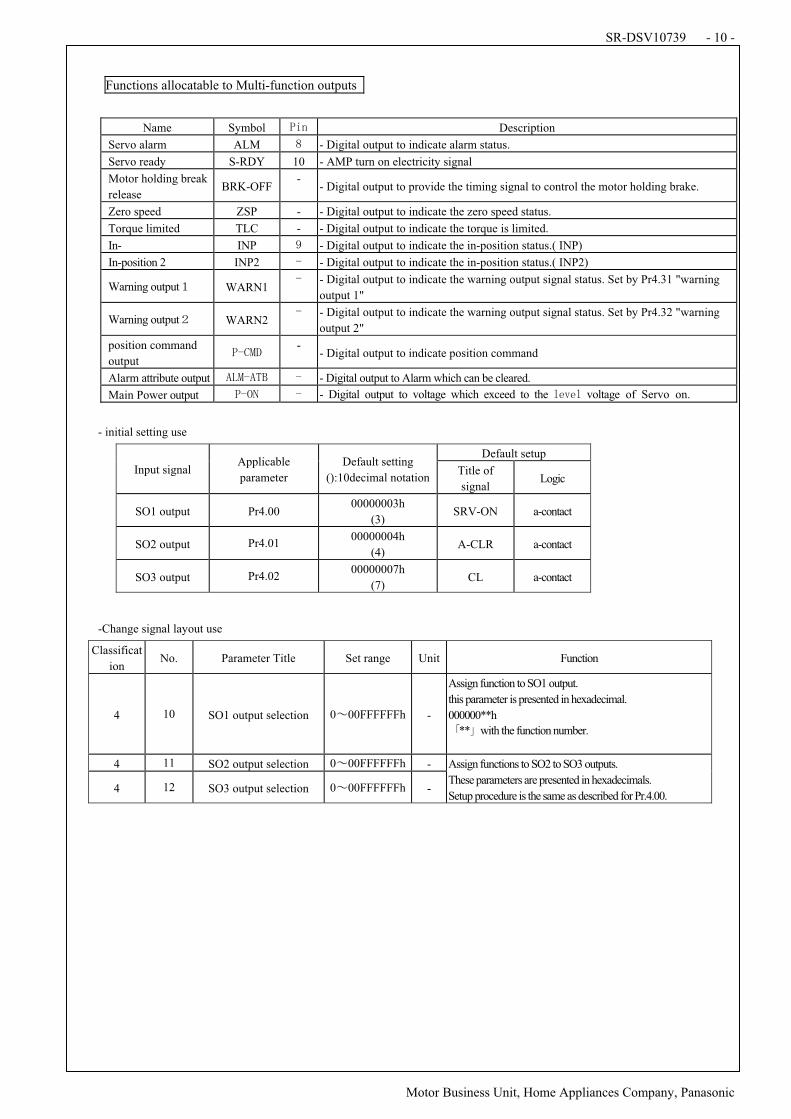
Functions allocatable to Multi-function outputs
- initial setting use
Default setup
Input signal Applicable
parameter
Default setting
():10decimal notationTitle of
signal Logic
SO1 output Pr4.00 00000003h
(3) SRV-ON a-contact
SO2 output Pr4.01 00000004h
(4) A-CLR a-contact
SO3 output Pr4.02 00000007h
(7) CL a-contact
-Change signal layout use
Classificat
ion No. Parameter Title Set range Unit Function
4 10 SO1 output selection 0N00FFFFFFh -
Assign function to SO1 output.
this parameter is presented in hexadecimal.
000000**h
L**Mwith the function number.
4 11 SO2 output selection 0N00FFFFFFh -
4 12 SO3 output selection 0N00FFFFFFh -
Assign functions to SO2 to SO3 outputs.
These parameters are presented in hexadecimals.
Setup procedure is the same as described for Pr.4.00.
Name Symbol Description
Servo alarm ALM - Digital output to indicate alarm status.
Servo ready S-RDY 10 - AMP turn on electricity signal
Motor holding break
release BRK-OFF
- - Digital output to provide the timing signal to control the motor holding brake.
Zero speed ZSP - - Digital output to indicate the zero speed status.
Torque limited TLC - - Digital output to indicate the torque is limited.
In- INP P - Digital output to indicate the in-position status.( INP)
In-position 2 INP2 H! - Digital output to indicate the in-position status.( INP2)
Warning outputQ WARN1 H! - Digital output to indicate the warning output signal status. Set by Pr4.31 "warning
output 1"
Warning outputR WARN2 H! - Digital output to indicate the warning output signal status. Set by Pr4.32 "warning
output 2"
position command
output 'HS>8!
- - Digital output to indicate position command
Alarm attribute output TG>HTF1! H - Digital output to Alarm which can be cleared.
Main Power output 'HKU! H - Digital output to voltage which exceed to the *)V)* voltage of Servo on.
SR-DSV10739 - 11 -
! ! ! Motor Business Unit, Home Appliances Company, Panasonic
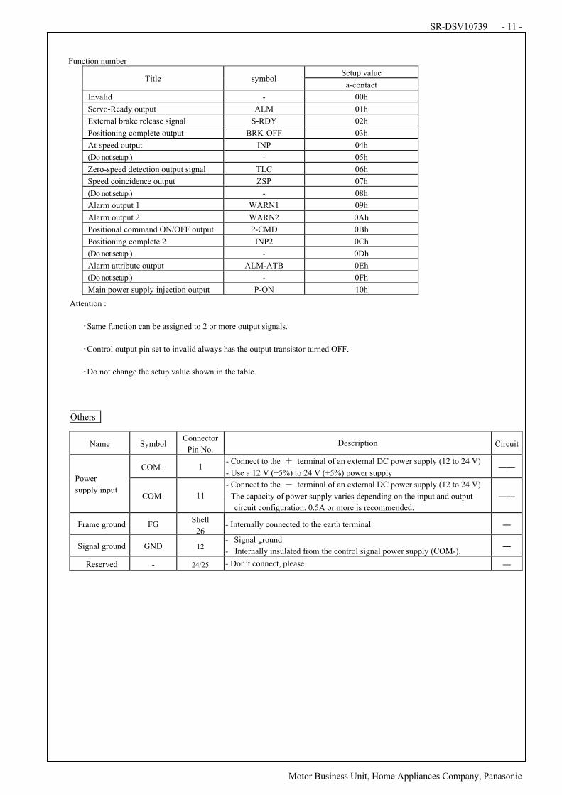
Function number
Setup value Title symbol
a-contact
Invalid - 00h
Servo-Ready output ALM 01h
External brake release signal S-RDY 02h
Positioning complete output BRK-OFF 03h
At-speed output INP 04h
(Do not setup.) - 05h
Zero-speed detection output signal TLC 06h
Speed coincidence output ZSP 07h
(Do not setup.) - 08h
Alarm output 1 WARN1 09h
Alarm output 2 WARN2 0Ah
Positional command ON/OFF output P-CMD 0Bh
Positioning complete 2 INP2 0Ch
(Do not setup.) - 0Dh
Alarm attribute output ALM-ATB 0Eh
(Do not setup.) - 0Fh
Main power supply injection output P-ON 10h
Attention :
OSame function can be assigned to 2 or more output signals.
OControl output pin set to invalid always has the output transistor turned OFF.
ODo not change the setup value shown in the table.
Others
Name Symbol Connector
Pin No. Description Circuit
COM+ - Connect to the W terminal of an external DC power supply (12 to 24 V)
- Use a 12 V (±5%) to 24 V (±5%) power supply ""
Power
supply input COM- 1
- Connect to the . terminal of an external DC power supply (12 to 24 V)
- The capacity of power supply varies depending on the input and output
circuit configuration. 0.5A or more is recommended.
""
Frame ground FG Shell
26 - Internally connected to the earth terminal. "
Signal ground GND 12 - Signal ground
- Internally insulated from the control signal power supply (COM-). "
Reserved - 24/25 - Don’t connect, please "
SR-DSV10739 - 12 -
! ! ! Motor Business Unit, Home Appliances Company, Panasonic
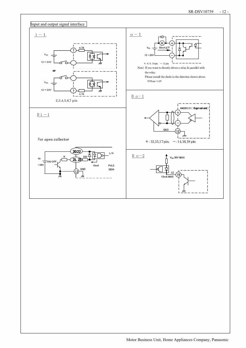
Input and output signal interface
!
!
!
!
!
!
!
!
!
!
!
!
!
!
!
!
!
!
!
!
!
!
!
!
!
!
!
!
!
!
!
!
!
!
X.Q Y.Q
!
"#$#%&'
&()'
%*!+'
"# $#%&'
&()'
%*!+'
or '
!
2,3,4,5,6,7 pin
''''',-8.9.10 pin. /-11 pin
Note0 If you want to directly driver a relay,In parallel with
the relay.
Please install the diode in the direction shown above.
' ' ' ' ' VCE sat = 1.2V
&()
"#$#%&
123456
7 ,
/
48#9):"! Equi val ent" '
;<("#'
'',-12,15,17pin. /-14,16,18 pin
,'
/'
.
For open collector
##2'
;<('"#'
21. 23!
20"22!
#$%&!
'!()!
!
*+,(!
-./0
123-
345
604677!
!"
89!
(::!;$(!<&=!
#>%&!<&=#?!
"
SR-DSV10739 - 13 -
# # # Motor Business Unit, Home Appliances Company, Panasonic
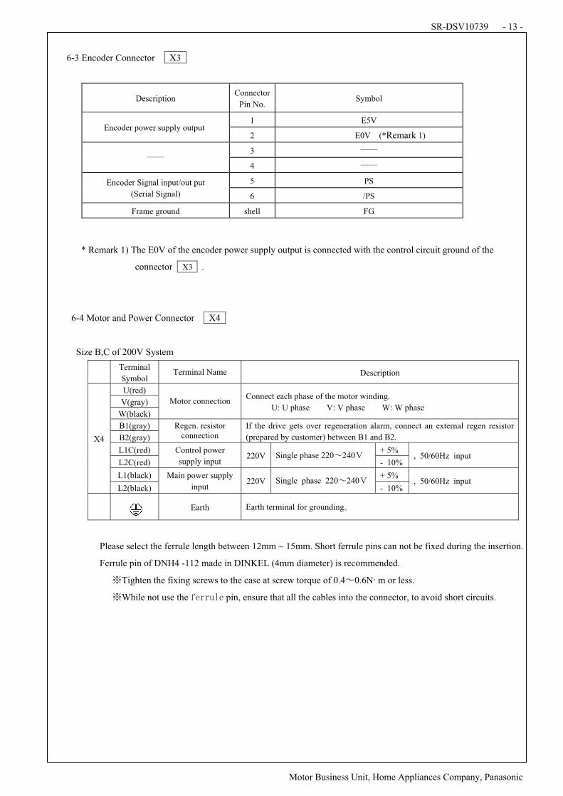
# 6-3 Encoder Connector X3
Description Connector
Pin No. Symbol
1 E5V Encoder power supply output
2 E0V (*Remark 1)
3 $$ $$
4 $$
5 PS Encoder Signal input/out put
(Serial Signal) 6 /PS
Frame ground shell FG
* Remark 1) The E0V of the encoder power supply output is connected with the control circuit ground of the
connector X3 .
6-4 Motor and Power Connector# X4
Size B,C of 200V System
Terminal#
Symbol Terminal Name Description
U(red)
V(gray)
W(black)
Motor connection Connect each phase of the motor winding.
U: U phase V: V phase W: W phase
B1(gray)
B2(gray)
Regen. resistor connection
If the drive gets over regeneration alarm, connect an external regen resistor
(prepared by customer) between B1 and B2.
L1C(red) + 5%
L2C(red)
Control power
supply input 220V Single phase 220%240&
- 10% , 50/60Hz input
L1(black) + 5%
X4
L2(black)
Main power supply
input 220V Single phase 220%240&
- 10% , 50/60Hz input
Earth Earth terminal for grounding'
Please select the ferrule length between 12mm ~ 15mm. Short ferrule pins can not be fixed during the insertion.
Ferrule pin of DNH4 -112 made in DINKEL (4mm diameter) is recommended.
(Tighten the fixing screws to the case at screw torque of 0.4%0.6N)m or less.
(While not use the pin, ensure that all the cables into the connector, to avoid short circuits.
#
#
#
#
#
#
#
#
#
#
#
#
#
#
SR-DSV10739 - 14 -
# # # Motor Business Unit, Home Appliances Company, Panasonic
#
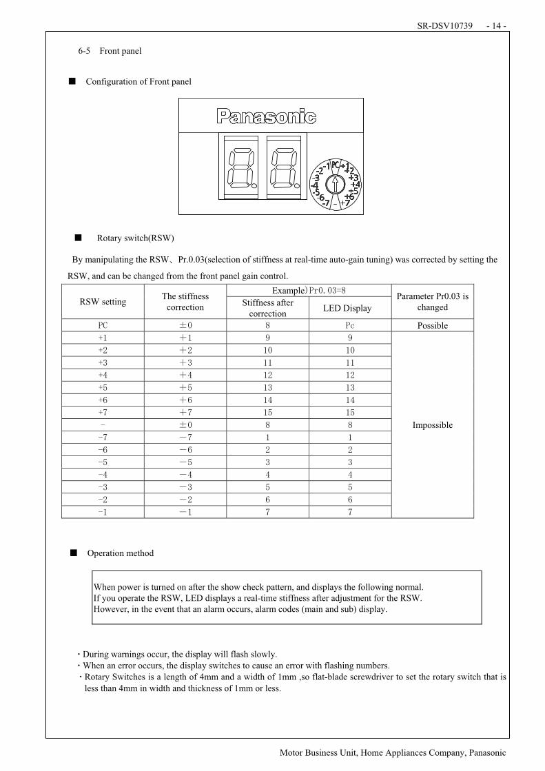
6-5# Front panel
*# Configuration of Front panel#
##*# Rotary switch(RSW)
By manipulating the RSW+Pr.0.03(selection of stiffness at real-time auto-gain tuning) was corrected by setting the
RSW, and can be changed from the front panel gain control.
Example,-./0/123#RSW setting
The stiffness correction
Stiffness after correction
LED Display
Parameter Pr0.03 is changed
-4# 5/# 3# -6# Possible#
78# 98# :# :#
7;# 9;# 8/# 8/#
71# 91# 88# 88#
7<# 9<# 8;# 8;#
7=# 9=# 81# 81#
7># 9># 8<# 8<#
7?# 9?# 8=# 8=#
@# 5/# 3# 3#
@?# "?# 8# 8#
@># "># ;# ;#
@=# "=# 1# 1#
@<# "<# <# <#
@1# "1# =# =#
@;# ";# ># >#
@8# "8# ?# ?#
Impossible#
#
*# Operation method#
#
When power is turned on after the show check pattern, and displays the following normal. If you operate the RSW, LED displays a real-time stiffness after adjustment for the RSW. However, in the event that an alarm occurs, alarm codes (main and sub) display.
#
#
ADuring warnings occur, the display will flash slowly.#
AWhen an error occurs, the display switches to cause an error with flashing numbers.
ARotary Switches is a length of 4mm and a width of 1mm ,so flat-blade screwdriver to set the rotary switch that is
less than 4mm in width and thickness of 1mm or less.
LIQI
Page 1
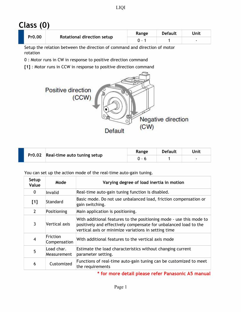
Class (0)
Pr0.00 Rotational direction setupRange Default Unit
0 – 1 1 -
0 : Motor runs in CW in response to positive direction command
Pr0.02 Real-time auto tuning setupRange Default Unit
0 – 6 1 -
You can set up the action mode of the real-time auto-gain tuning.
Mode Varying degree of load inertia in motion
0 Invalid Real-time auto-gain tuning function is disabled.
[1] Standard
2 Positioning Main application is positioning.
3 Vertical axis
4 With additional features to the vertical axis mode
5
6 Customized
* for more detail please refer Panasonic A5 manual
Setup the relation between the direction of command and direction of motor
rotation
[1] : Motor runs in CCW in response to positive direction command
Setup
Value
Basic mode. Do not use unbalanced load, friction compensation or
gain switching.
With additional features to the positioning mode - use this mode to
positively and effectively compensate for unbalanced load to the
vertical axis or minimize variations in setting time
Friction
Compensation
Load char.
Measurement
Estimate the load characteristics without changing current
parameter setting.
Functions of real-time auto-gain tuning can be customized to meet
the requirements
LIQI
Page 2
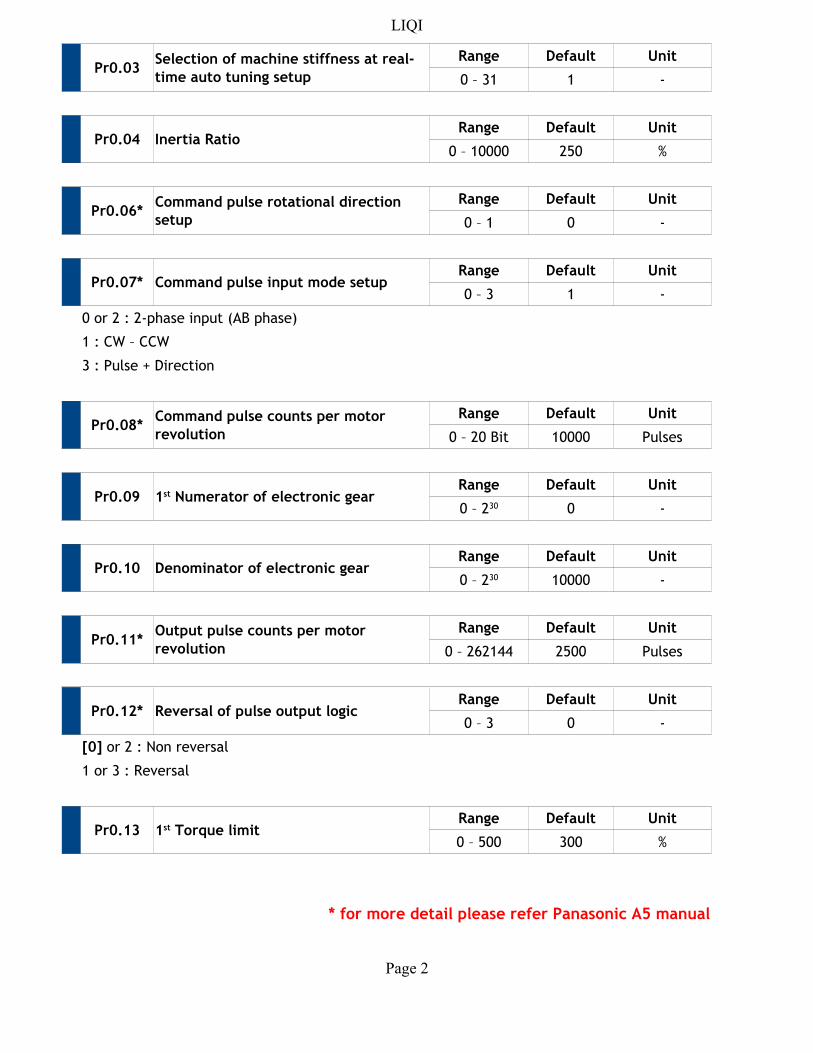
Pr0.03Range Default Unit
0 – 31 1 -
Pr0.04 Inertia RatioRange Default Unit
0 – 10000 250 %
Pr0.06*Range Default Unit
0 – 1 0 -
Pr0.07* Command pulse input mode setupRange Default Unit
0 – 3 1 -
0 or 2 : 2-phase input (AB phase)
1 : CW – CCW
3 : Pulse + Direction
Pr0.08*Range Default Unit
0 – 20 Bit 10000 Pulses
Pr0.09Range Default Unit
0 -
Pr0.10 Denominator of electronic gearRange Default Unit
10000 -
Pr0.11*Range Default Unit
0 – 262144 2500 Pulses
Pr0.12* Reversal of pulse output logicRange Default Unit
0 – 3 0 -
1 or 3 : Reversal
Pr0.13Range Default Unit
0 – 500 300 %
* for more detail please refer Panasonic A5 manual
Selection of machine stiffness at real-
time auto tuning setup
Command pulse rotational direction
setup
Command pulse counts per motor
revolution
1st Numerator of electronic gear0 – 230
0 – 230
Output pulse counts per motor
revolution
[0] or 2 : Non reversal
1st Torque limit
LIQI
Page 3
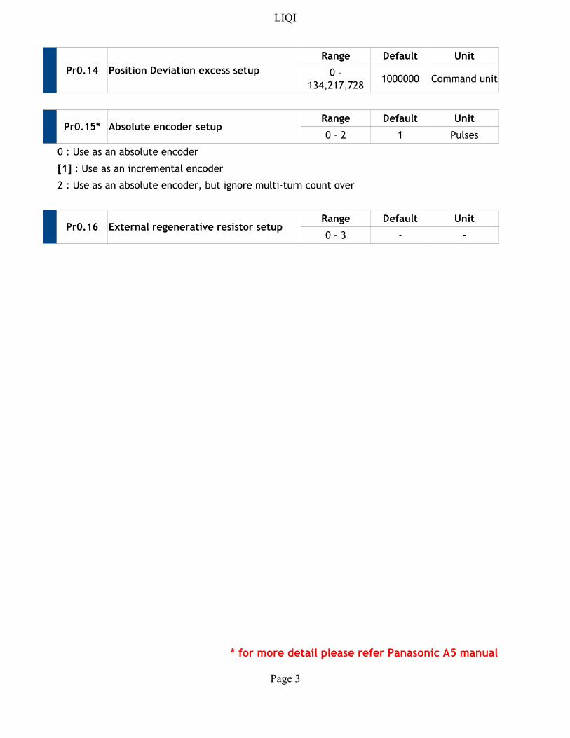
Pr0.14 Position Deviation excess setup
Range Default Unit
1000000 Command unit
Pr0.15* Absolute encoder setupRange Default Unit
0 – 2 1 Pulses
0 : Use as an absolute encoder
Pr0.16 External regenerative resistor setupRange Default Unit
0 – 3 - -
* for more detail please refer Panasonic A5 manual
0 –
134,217,728
[1] : Use as an incremental encoder
2 : Use as an absolute encoder, but ignore multi-turn count over
LIQI
Page 4
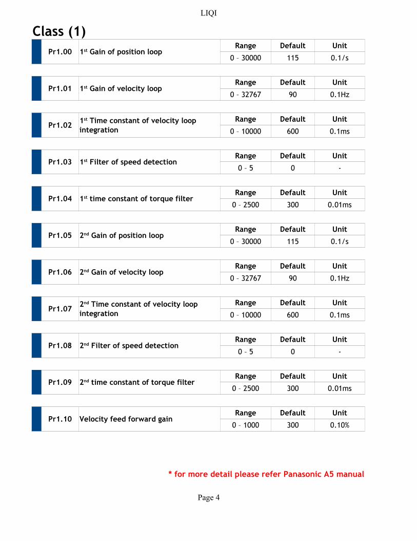
Class (1)
Pr1.00Range Default Unit
0 – 30000 115 0.1/s
Pr1.01Range Default Unit
0 – 32767 90 0.1Hz
Pr1.02Range Default Unit
0 – 10000 600 0.1ms
Pr1.03Range Default Unit
0 – 5 0 -
Pr1.04Range Default Unit
0 – 2500 300 0.01ms
Pr1.05Range Default Unit
0 – 30000 115 0.1/s
Pr1.06Range Default Unit
0 – 32767 90 0.1Hz
Pr1.07Range Default Unit
0 – 10000 600 0.1ms
Pr1.08Range Default Unit
0 – 5 0 -
Pr1.09Range Default Unit
0 – 2500 300 0.01ms
Pr1.10 Velocity feed forward gainRange Default Unit
0 – 1000 300 0.10%
* for more detail please refer Panasonic A5 manual
1st Gain of position loop
1st Gain of velocity loop
1st Time constant of velocity loop
integration
1st Filter of speed detection
1st time constant of torque filter
2nd Gain of position loop
2nd Gain of velocity loop
2nd Time constant of velocity loop
integration
2nd Filter of speed detection
2nd time constant of torque filter
LIQI
Page 5
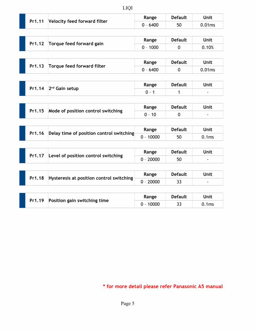
Pr1.11 Velocity feed forward filterRange Default Unit
0 – 6400 50 0.01ms
Pr1.12 Torque feed forward gainRange Default Unit
0 – 1000 0 0.10%
Pr1.13 Torque feed forward filterRange Default Unit
0 – 6400 0 0.01ms
Pr1.14Range Default Unit
0 – 1 1 -
Pr1.15 Mode of position control switchingRange Default Unit
0 – 10 0 -
Pr1.16 Delay time of position control switchingRange Default Unit
0 – 10000 50 0.1ms
Pr1.17 Level of position control switchingRange Default Unit
0 – 20000 50 -
Pr1.18Range Default Unit
0 – 20000 33 -
Pr1.19 Position gain switching timeRange Default Unit
0 – 10000 33 0.1ms
* for more detail please refer Panasonic A5 manual
2nd Gain setup
Hysteresis at position control switching
LIQI
Page 6
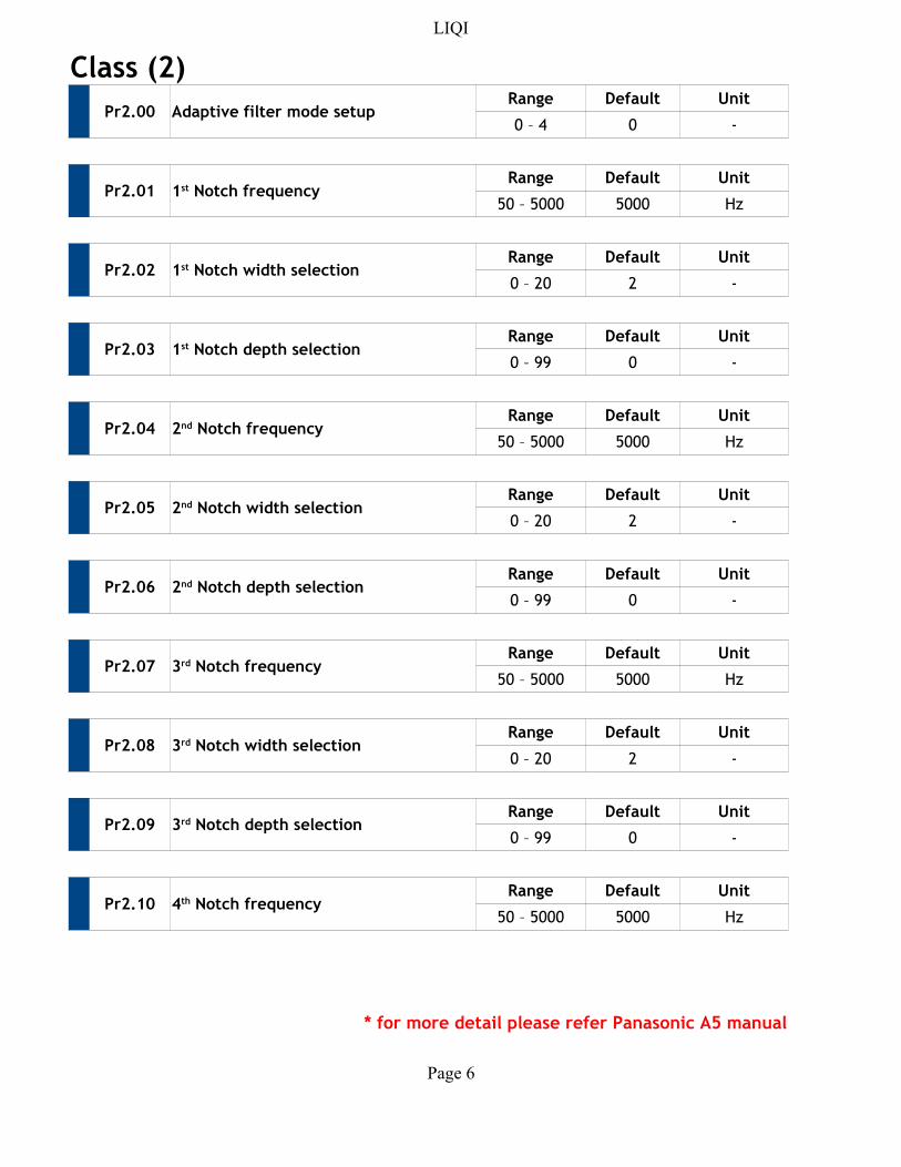
Class (2)
Pr2.00 Adaptive filter mode setupRange Default Unit
0 – 4 0 -
Pr2.01Range Default Unit
50 – 5000 5000 Hz
Pr2.02Range Default Unit
0 – 20 2 -
Pr2.03Range Default Unit
0 – 99 0 -
Pr2.04Range Default Unit
50 – 5000 5000 Hz
Pr2.05Range Default Unit
0 – 20 2 -
Pr2.06Range Default Unit
0 – 99 0 -
Pr2.07Range Default Unit
50 – 5000 5000 Hz
Pr2.08Range Default Unit
0 – 20 2 -
Pr2.09Range Default Unit
0 – 99 0 -
Pr2.10Range Default Unit
50 – 5000 5000 Hz
* for more detail please refer Panasonic A5 manual
1st Notch frequency
1st Notch width selection
1st Notch depth selection
2nd Notch frequency
2nd Notch width selection
2nd Notch depth selection
3rd Notch frequency
3rd Notch width selection
3rd Notch depth selection
4th Notch frequency
LIQI
Page 7
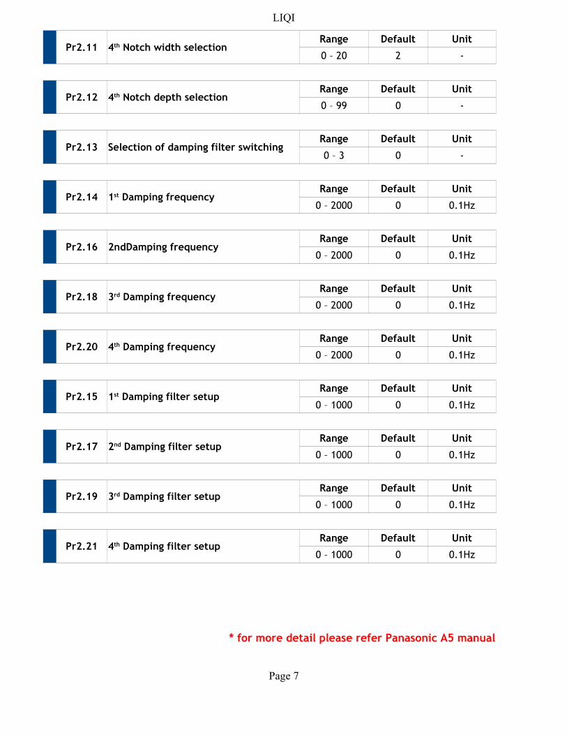
Pr2.11Range Default Unit
0 – 20 2 -
Pr2.12Range Default Unit
0 – 99 0 -
Pr2.13 Selection of damping filter switchingRange Default Unit
0 – 3 0 -
Pr2.14Range Default Unit
0 – 2000 0 0.1Hz
Pr2.16 2ndDamping frequencyRange Default Unit
0 – 2000 0 0.1Hz
Pr2.18Range Default Unit
0 – 2000 0 0.1Hz
Pr2.20Range Default Unit
0 – 2000 0 0.1Hz
Pr2.15Range Default Unit
0 – 1000 0 0.1Hz
Pr2.17Range Default Unit
0 – 1000 0 0.1Hz
Pr2.19Range Default Unit
0 – 1000 0 0.1Hz
Pr2.21Range Default Unit
0 – 1000 0 0.1Hz
* for more detail please refer Panasonic A5 manual
4th Notch width selection
4th Notch depth selection
1st Damping frequency
3rd Damping frequency
4th Damping frequency
1st Damping filter setup
2nd Damping filter setup
3rd Damping filter setup
4th Damping filter setup
LIQI
Page 8
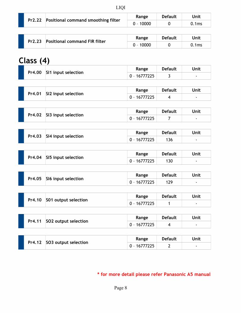
Pr2.22 Positional command smoothing filterRange Default Unit
0 – 10000 0 0.1ms
Pr2.23 Positional command FIR filterRange Default Unit
0 – 10000 0 0.1ms
Class (4)
Pr4.00 SI1 input selectionRange Default Unit
0 – 16777225 3 -
Pr4.01 SI2 input selectionRange Default Unit
0 – 16777225 4 -
Pr4.02 SI3 input selectionRange Default Unit
0 – 16777225 7 -
Pr4.03 SI4 input selectionRange Default Unit
0 – 16777225 136 -
Pr4.04 SI5 input selectionRange Default Unit
0 – 16777225 130 -
Pr4.05 SI6 input selectionRange Default Unit
0 – 16777225 129 -
Pr4.10 S01 output selectionRange Default Unit
0 – 16777225 1 -
Pr4.11 SO2 output selectionRange Default Unit
0 – 16777225 4 -
Pr4.12 SO3 output selectionRange Default Unit
0 – 16777225 2 -
* for more detail please refer Panasonic A5 manual
LIQI
Page 9
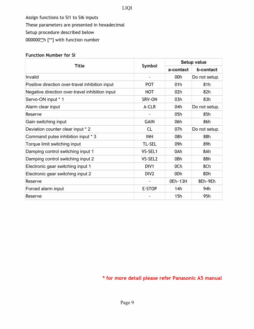
Assign functions to SI1 to SI6 inputs
These parameters are presented in hexadecimal
Setup procedure described below
Function Number for SI
Title SymbolSetup value
a-contact b-contact
Invalid - 00h Do not setup.
Positive direction over-travel inhibition input POT 01h 81h
Negative direction over-travel inhibition input NOT 02h 82h
Servo-ON input * 1 SRV-ON 03h 83h
Alarm clear input A-CLR 04h Do not setup.
Reserve - 05h 85h
Gain switching input GAIN 06h 86h
Deviation counter clear input * 2 CL 07h Do not setup.
Command pulse inhibition input * 3 INH 08h 88h
Torque limit switching input TL-SEL 09h 89h
Damping control switching input 1 VS-SEL1 0Ah 8Ah
Damping control switching input 2 VS-SEL2 0Bh 8Bh
Electronic gear switching input 1 DIV1 0Ch 8Ch
Electronic gear switching input 2 DIV2 0Dh 8Dh
Reserve - 0Eh~13H 8Eh~9Eh
Forced alarm input E-STOP 14h 94h
Reserve - 15h 95h
* for more detail please refer Panasonic A5 manual
000000**h [**] with function number
LIQI
Page 10
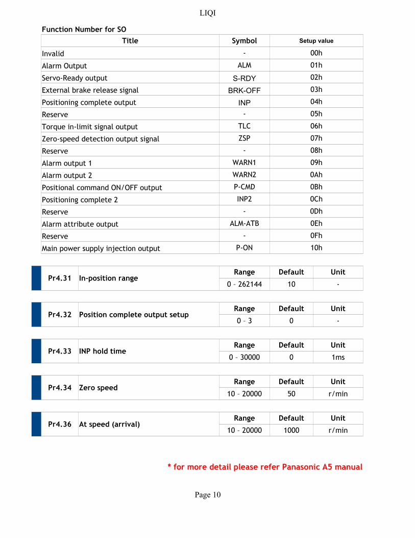
Function Number for SO
Title Symbol Setup value
Invalid - 00h
Alarm Output ALM 01h
Servo-Ready output S-RDY 02h
External brake release signal BRK-OFF 03h
Positioning complete output INP 04h
Reserve - 05h
Torque in-limit signal output TLC 06h
Zero-speed detection output signal ZSP 07h
Reserve - 08h
Alarm output 1 WARN1 09h
Alarm output 2 WARN2 0Ah
Positional command ON/OFF output P-CMD 0Bh
Positioning complete 2 INP2 0Ch
Reserve - 0Dh
Alarm attribute output ALM-ATB 0Eh
Reserve - 0Fh
Main power supply injection output P-ON 10h
Pr4.31 In-position rangeRange Default Unit
0 – 262144 10 -
Pr4.32 Position complete output setupRange Default Unit
0 – 3 0 -
Pr4.33 INP hold timeRange Default Unit
0 – 30000 0 1ms
Pr4.34 Zero speedRange Default Unit
10 – 20000 50 r/min
Pr4.36 At speed (arrival)Range Default Unit
10 – 20000 1000 r/min
* for more detail please refer Panasonic A5 manual
LIQI
Page 11
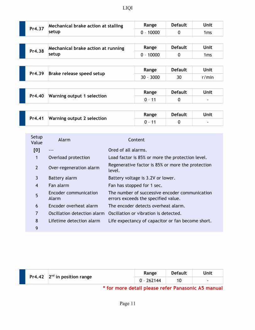
Pr4.37Range Default Unit
0 – 10000 0 1ms
Pr4.38Range Default Unit
0 – 10000 0 1ms
Pr4.39 Brake release speed setupRange Default Unit
30 – 3000 30 r/min
Pr4.40 Warning output 1 selectionRange Default Unit
0 – 11 0 -
Pr4.41 Warning output 2 selectionRange Default Unit
0 – 11 0 -
Alarm Content
[0] ---
1 Overload protection Load factor is 85% or more the protection level.
2 Over-regeneration alarm
3 Battery alarm Battery voltage is 3.2V or lower.
4 Fan alarm Fan has stopped for 1 sec.
5
6 Encoder overheat alarm The encoder detects overheat alarm.
7 Oscillation detection alarm Oscillation or vibration is detected.
8 Lifetime detection alarm Life expectancy of capacitor or fan become short.
9
Pr4.42Range Default Unit
0 – 262144 10 -
* for more detail please refer Panasonic A5 manual
Mechanical brake action at stalling
setup
Mechanical brake action at running
setup
Setup
Value
Ored of all alarms.
Regenerative factor is 85% or more the protection
level.
Encoder communication
Alarm
The number of successive encoder communication
errors exceeds the specified value.
2nd in position range
LIQI
Page 12
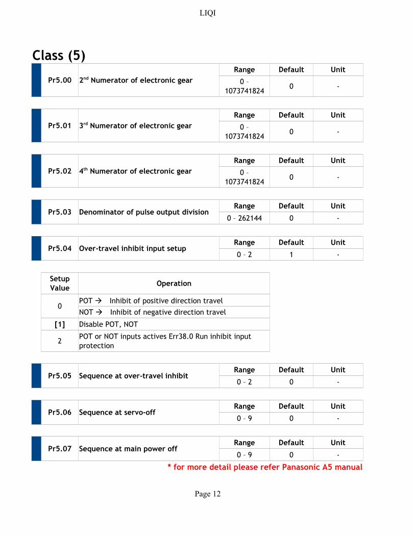
Class (5)
Pr5.00
Range Default Unit
0 -
Pr5.01
Range Default Unit
0 -
Pr5.02
Range Default Unit
0 -
Pr5.03 Denominator of pulse output divisionRange Default Unit
0 – 262144 0 -
Pr5.04 Over-travel inhibit input setupRange Default Unit
0 – 2 1 -
Operation
0
[1] Disable POT, NOT
2
Pr5.05 Sequence at over-travel inhibitRange Default Unit
0 – 2 0 -
Pr5.06 Sequence at servo-offRange Default Unit
0 – 9 0 -
Pr5.07 Sequence at main power offRange Default Unit
0 – 9 0 -
* for more detail please refer Panasonic A5 manual
2nd Numerator of electronic gear 0 –
1073741824
3rd Numerator of electronic gear 0 –
1073741824
4th Numerator of electronic gear 0 –
1073741824
Setup
Value
POT Inhibit of positive direction travel
NOT Inhibit of negative direction travel
POT or NOT inputs actives Err38.0 Run inhibit input
protection
LIQI
Page 13
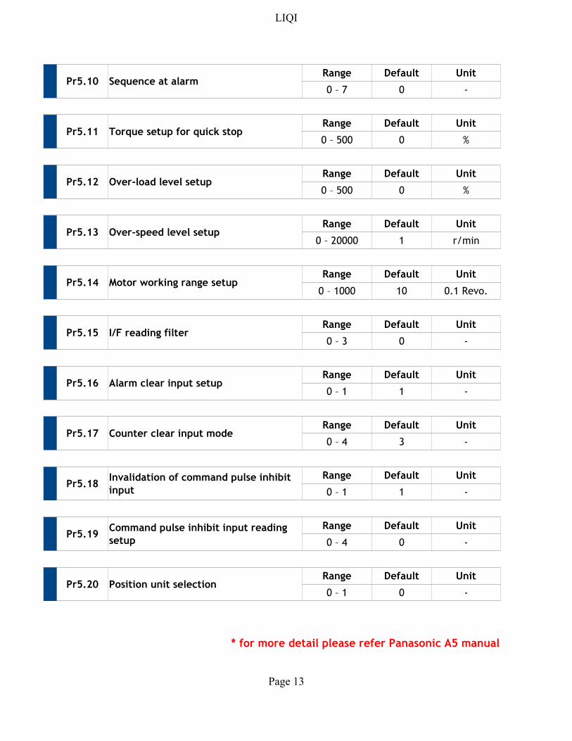
Pr5.10 Sequence at alarmRange Default Unit
0 – 7 0 -
Pr5.11 Torque setup for quick stopRange Default Unit
0 – 500 0 %
Pr5.12 Over-load level setupRange Default Unit
0 – 500 0 %
Pr5.13 Over-speed level setupRange Default Unit
0 – 20000 1 r/min
Pr5.14 Motor working range setupRange Default Unit
0 – 1000 10
Pr5.15 I/F reading filterRange Default Unit
0 – 3 0 -
Pr5.16 Alarm clear input setupRange Default Unit
0 – 1 1 -
Pr5.17 Counter clear input modeRange Default Unit
0 – 4 3 -
Pr5.18Range Default Unit
0 – 1 1 -
Pr5.19Range Default Unit
0 – 4 0 -
Pr5.20 Position unit selectionRange Default Unit
0 – 1 0 -
* for more detail please refer Panasonic A5 manual
0.1 Revo.
Invalidation of command pulse inhibit
input
Command pulse inhibit input reading
setup
LIQI
Page 14
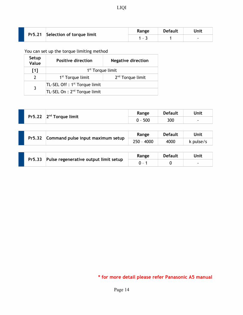
Pr5.21 Selection of torque limitRange Default Unit
1 – 3 1 -
You can set up the torque limiting method
Positive direction Negative direction
[1]
2
3
Pr5.22Range Default Unit
0 – 500 300 -
Pr5.32 Command pulse input maximum setupRange Default Unit
250 – 4000 4000 k pulse/s
Pr5.33 Pulse regenerative output limit setupRange Default Unit
0 – 1 0 -
* for more detail please refer Panasonic A5 manual
Setup
Value
1st Torque limit
1st Torque limit 2nd Torque limit
TL-SEL Off : 1st Torque limit
TL-SEL On : 2nd Torque limit
2nd Torque limit
LIQI
Page 15
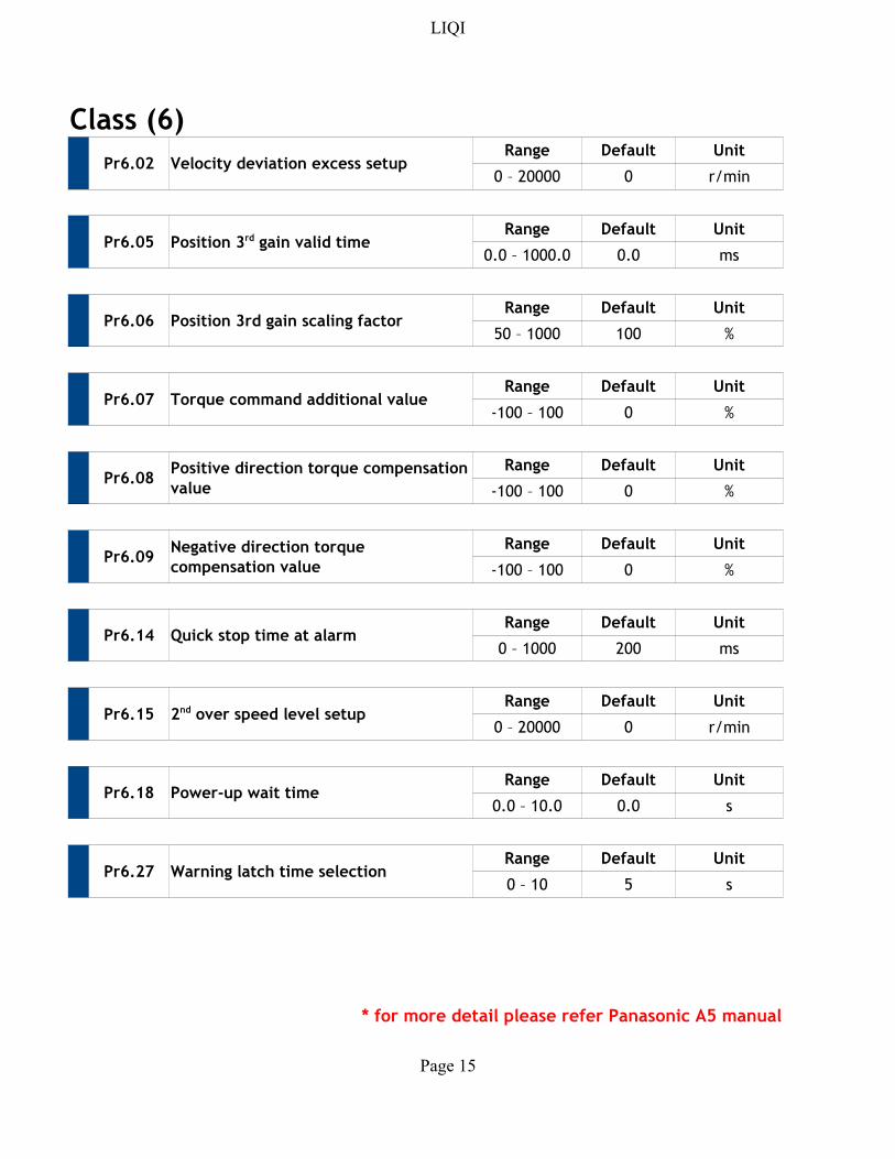
Class (6)
Pr6.02 Velocity deviation excess setupRange Default Unit
0 – 20000 0 r/min
Pr6.05Range Default Unit
0.0 – 1000.0 0.0 ms
Pr6.06 Position 3rd gain scaling factorRange Default Unit
50 – 1000 100 %
Pr6.07 Torque command additional valueRange Default Unit
-100 – 100 0 %
Pr6.08Range Default Unit
-100 – 100 0 %
Pr6.09Range Default Unit
-100 – 100 0 %
Pr6.14 Quick stop time at alarmRange Default Unit
0 – 1000 200 ms
Pr6.15Range Default Unit
0 – 20000 0 r/min
Pr6.18 Power-up wait timeRange Default Unit
0.0 – 10.0 0.0 s
Pr6.27 Warning latch time selectionRange Default Unit
0 – 10 5 s
* for more detail please refer Panasonic A5 manual
Position 3rd gain valid time
Positive direction torque compensation
value
Negative direction torque
compensation value
2nd over speed level setup
LIQI
Page 16
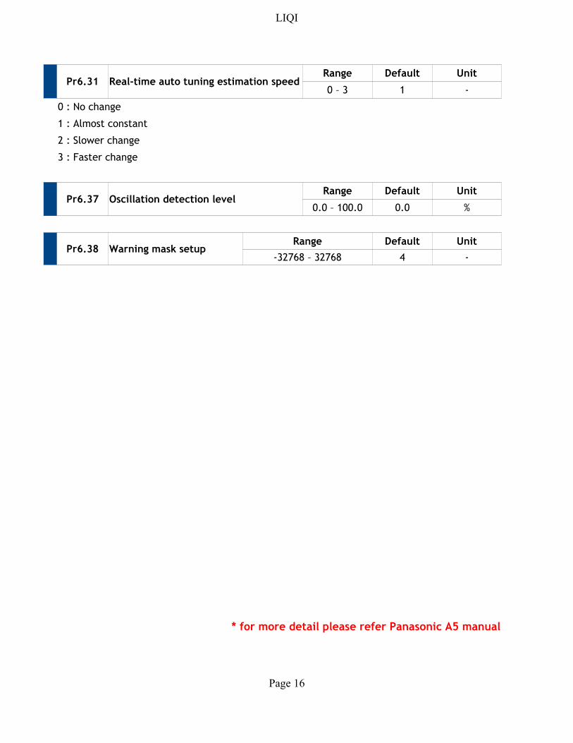
Pr6.31 Real-time auto tuning estimation speedRange Default Unit
0 – 3 1 -
0 : No change
1 : Almost constant
2 : Slower change
3 : Faster change
Pr6.37 Oscillation detection levelRange Default Unit
0.0 – 100.0 0.0 %
Pr6.38 Warning mask setupRange Default Unit
-32768 – 32768 4 -
* for more detail please refer Panasonic A5 manual