Embed Size (px)
Citation preview

PANDORA DAC
ROMULUS CD Player-DAC
Owner’s Manual
Aesthetix Audio Corporation
5220 Gabbert Rd., Suite A ♦ Moorpark, CA. 93021 Phone: (805) 529-9901

The lightning flash with arrowhead symbol, within an equilateral triangle, is intended to alert the user to the presence of uninsulated “dangerous voltage” within the product’s enclosure that may be of significant magnitude to constitute a risk of electric shock to persons. The exclamation point within an equilateral triangle is intended to alert the user to the presence of important operating and maintenance (servicing) instructions in the literature accompanying the product.
WARNING
TO REDUCE THE RISK OF FIRE OR ELECTRIC SHOCK, DO NOT EXPOSE THIS PRODUCT TO RAIN OR MOISTURE
CAUTION: TO PREVENT ELECTRIC SHOCK, DO NOT USE THE AC (POLARIZED) PLUG WITH AN EXTENSION CORD, RECEPTACLE OR OTHER OUTLET UNLESS THE BLADES CAN BE FULLY INSERTED TO PREVENT BLADE EXPOSURE. Extension cords are not recommended for use with this product.
2
3
PREFACE INTRODUCTION
This manual covers the use for both the Pandora DAC and The Romulus DAC/CD Player. The name Pandora will be used where it applies to both products and the name Romulus will be used where it applies to the Romulus only. Thank you for purchasing the Pandora/Romulus CD player-DAC. It has been engineered to deliver the highest attainable sound quality. This is its sole purpose. Only the highest grade electronic components are used in the Pandora, including: non-inductive Roederstein metal film resistors in the signal path; polystyrene, polypropylene, and electrolytic power supply, bypass, and signal capacitors; low noise matched vacuum tubes; glass epoxy circuit boards; 16 gauge aluminum chassis; custom wound low flux power transformers. The integration of the personal computer (PC) into the home stereo system has provided a revolutionary way to purchase, organize, and play your digital music collection. The Pandora digital-to-audio (D/A or DAC) converter provides an equally revolutionary way to play back your music files with unprecedented fidelity and realism. Connected via the omnipresent USB port, the Pandora generates a fixed-frequency master audio clock and requests the data from the computer at the correct time for jitter-free playback of your music. This is all done using the standard device drivers (up to 96K for Windows, additional driver required for 192K) supplied with all recent operating systems, allowing simple installation and operation with most computers. The Pandora also utilizes opto-couplers to provide total electrical isolation for the connections between your computer and music system. This minimizes the introduction of unwanted radio-frequency interference (RFI), generated by all computers. Note: Avoiding the use of wireless networks (e.g., Wi-Fi) by employing wired connections instead, will reduce RFI levels in your home and results in improved sound quality for any music system.
PLACEMENT The Pandora should be located away from possible sources of hum such as power cords, power transformers and the like. It should not be located near any other heat source such as a power amplifier or power supply. It must be kept well ventilated any time it is on. If it is positioned within an enclosed space then fans may be warranted. All air vents must remain unobstructed.
BURN IN TIME This unit has a break in period of about 400 hours during which continuous improvement in sound quality will be observed.
4
IMPORTANT Save all packaging in a dry place away from fire hazards. Your Pandora is a precision electronic instrument and should be properly packaged any time shipment is made. In the unlikely event that you have to return your Pandora to the factory for service, or if you send it to us for updating, the original packaging will best protect the unit from shipping damage. In order to achieve the fullest flexibility and enjoyment from your Pandora, we highly recommend that you read this manual in full before connecting the unit to your audio system. Note: It is imperative that the Pandora be operated in a well ventilated environment and the
immediate external temperature be maintained as specified. External cooling fans may be required in some cases. Do not stack any equipment directly above or below the Pandora to protect it from overheating, as well as the continued functionality of any equipment near and around it.
WARNING United States law prohibits disposition of these commodities to Libya, Laos, North Korea, Cambodia or Cuba unless otherwise authorized by the United States. AFTER MARKET and THIRD PARTY MODIFICATIONS Please note that any after market and/or third party modifications will void the warranty. In the case of changing the feet on a unit, in order to prevent any damage (which will also not be covered under warranty), please verify that the screws being used to secure non-Aesthetix feet do not screw any deeper into the chassis than the original ones. The original screw is 10-32 by 3/8” and extends into the chassis 1/8 inch. Acknowledgements © 2011-20 Aesthetix Audio Corporation. All rights reserved. Written and Illustrated by Glenn Buckley No part of this publication may be reproduced or transmitted in any form or by any means, electronic or mechanical, for any purpose, without the express written permission of Aesthetix Audio Corporation.

5
SAFETY PRECAUTIONS Please carefully read each item of the operating instructions and safety precautions before installing and using this product. Use extra care to follow the warnings written on the product itself and/or in the operating instructions. Keep the operating instructions and safety precautions for future reference. CAUTION: TO REDUCE THE RISK OF ELECTRICAL SHOCK, DO NOT REMOVE ANY OF THE COVER PANELS.
NO USER-SERVICEABLE PARTS INSIDE. REFER ALL SERVICING TO QUALIFIED SERVICE PERSONNEL ONLY.
TO PREVENT FIRE OR SHOCK HAZARD, DO NOT ALLOW LIQUIDS TO SPILL OR OBJECTS TO FALL INTO ANY OPENINGS OF THE PRODUCT.
THIS UNIT IS SUPPLIED WITH A 3 PIN GROUNDED AC PLUG. ALWAYS INSERT THE AC PLUG INTO A GROUNDED OUTLET. DO NOT REMOVE THE GROUND PIN OR DISABLE THE GROUND FOR ANY PURPOSE.
BEFORE MAKING ANY CONNECTIONS TO THE PANDORA, FIRST TURN OFF THE POWER AND THEN DISCONNECT THE AC POWER CORD.
WHEN INSTALLING THE PANDORA IN YOUR SYSTEM, MAKE CERTAIN TO ALLOW A MINIMUM OF 4 INCHES OF VENTILATION ON EACH SIDE OF THE UNIT. ALSO ALLOW AT LEAST 3 INCHES OF VENTILATION SPACE ABOVE THE UNIT. IMPROPER VENTILATION OF THE UNIT MAY CAUSE OVERHEATING, WHICH MAY DAMAGE THE UNIT AND CAUSE A FIRE. PLACE THE UNIT ON A SOLID SURFACE ONLY. I.E. NOT ON CARPET, ETC.
DO NOT PLACE THE PANDORA NEAR HEAT SOURCES SUCH AS DIRECT SUNLIGHT, STOVES, HEAT REGISTERS, RADIATORS OR OTHER HEAT PRODUCING EQUIPMENT.
IF REPLACEMENT OF THE AC LINE FUSE AND/OR ANY INTERNAL FUSE BECOMES NECESSARY, REPLACE ONLY WITH SAME VALUE AND TYPE OF FUSE. NEVER BYPASS THE FUSE.
IF THE AC CORD BECOMES DAMAGED, DO NOT USE IT. IMMEDIATELY REPLACE IT WITH A NEW ONE OF THE SAME OR BETTER RATING.
IT IS IMPERATIVE THAT THE PANDORA BE OPERATED IN A WELL VENTILATED ENVIRONMENT AND THE IMMEDIATE EXTERNAL TEMPERATURE BE MAINTAINED AS SPECIFIED. EXTERNAL COOLING FANS MAY BE REQUIRED IN SOME CASES. DO NOT STACK ANY EQUIPMENT DIRECTLY ABOVE OR BELOW THE PANDORA AS TO PROTECT IT FROM OVERHEATING, AS WELL AS THE CONTINUED FUNCTIONALITY OF ANY EQUIPMENT NEAR AND AROUND IT.
IF THE TOP COVER HAS TO BE REMOVED, FIRST TURN OFF THE REAR PANEL POWER SWITCH AND WAIT A MINIMUM OF 15 MINUTES.
6
Table Of Contents
PREFACE............................................................................................................................3!INTRODUCTION ..............................................................................................................3!PLACEMENT....................................................................................................................3!BURN IN TIME .................................................................................................................3!IMPORTANT ....................................................................................................................4!WARNING........................................................................................................................4!
AFTER MARKET and THIRD PARTY MODIFICATIONS..............................................4!Acknowledgements........................................................................................................4!
SAFETY PRECAUTIONS ...................................................................................................5!The Hand Held Remote.......................................................................................................7!Pandora Front Panel Layout................................................................................................8!Pandora Display Layout.......................................................................................................9!Rear Panel Layout.............................................................................................................10!CONNECTIONS ................................................................................................................11!
AC Power: ......................................................................................................................11!USB Audio Input Speed..................................................................................................11!
OPERATION .....................................................................................................................12!STANDBY.......................................................................................................................12!INPUT Select Buttons.....................................................................................................12!MUTE .............................................................................................................................12!Volume Control (VC) ......................................................................................................12!DISPLAY ........................................................................................................................12!
Advanced display functionality.....................................................................................13!REMOTE TRIGGER.......................................................................................................13!RS232.............................................................................................................................13!Memory Buffering ...........................................................................................................13!SETUP............................................................................................................................13!
Configuring your computer ..........................................................................................13!Romulus.............................................................................................................................. 14!Romulus Front Panel Layout .............................................................................................14!Romulus Display Layout ....................................................................................................15!Operation...........................................................................................................................16!
INPUT.............................................................................................................................16!CD CONTROL buttons ...................................................................................................16!
Appendix A! Troubleshooting Guide ...............................................................................17!Display Codes ................................................................................................................17!
Appendix B! Specifications .............................................................................................18!
The Hand Held Remote
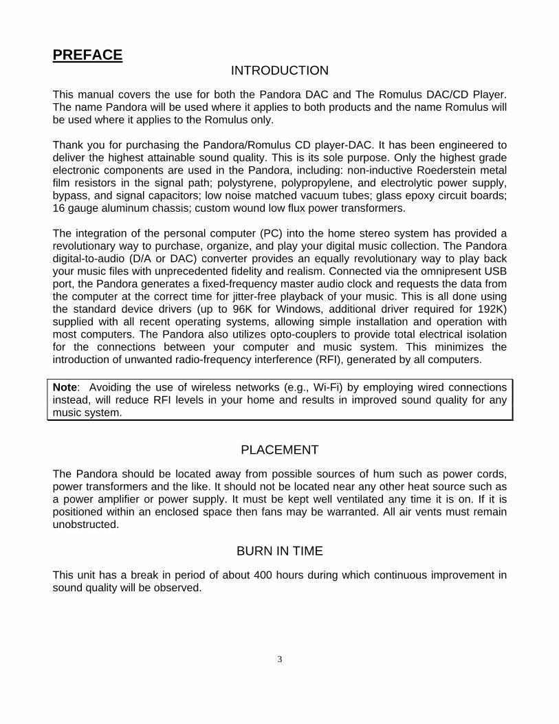
The Pandora/Romulus CD player-DAC can be controlled using either the front panel buttons or the supplied hand held remote control. Basic functions are selectable from both locations. Additional functions are accessible only on the remote control. This remote control can also be used with the Rhea, Calypso and Janus preamplifiers. Functions for these other products will be discussed in their respective Owner’s manuals. Please note that all CD functions apply to the Romulus only. 1. Standby button. Toggles the Pandora between Standby and Operate.
2. Display. Toggle to turn the Display on and off.
3. Numeric entry and Enter buttons.
4. Information button. Press to view track or disc information.
5. Repeat. Press once to repeat the current Romulus track, twice to repeat the current disc and 3 times to always repeat the entire disc, even if the disc has been changed.
6. Random Romulus track play.
7. Up and Down. Press to control volume when the optional volume controls are installed.
8. Mute. Say no more.
9. Left and Right. Not used.
10. Scan Back. When quickly pressed once, advances to the previous Romulus track and begins playing. When held, it scans back through the current track until released. Also closes the drawer, if open.
11. When pressed once quickly, advances to the next Romulus track and begins playing. When held, it scans forward through the current track until released. Also closes the drawer, if open.
12. Pauses the CD in play. Press Pause again, or play to continue playing the CD. Also closes the drawer, if open.
13. Stops the disc from playing.
14. Plays the current CD track. Restarts play when paused.
15. Eject. Opens or closes the drawer.
16. Input Select buttons.
17. Toggles absolute phase.
18. Pressing either the left of right Input arrow buttons motions the unit through its inputs.
19. Used to sync the video from a different device with the audio output of the Pandora.
20 - 23 N/A with Pandora.
24 - 26. Unit select buttons. Pandora/Romulus must be selected. Figure 1 – Hand Held Remote HRC-2
7

Pandora Front Panel Layout
STANDBY
AESTHETIX
1 4 5 1211 1332 6 7 8 9 10
PHASERNDM
ALL FOREVER
LOCK
ONE
REPEAT
AES
MUTE
RCA TOS USB AUX
PANDORA
DISPLAY
Figure 2 – Pandora Front Panel Layout 1. STANDBY button. After the rear panel MAIN POWER switch is turned on and the information pages are
displayed, press the front panel STANDBY button to exit the standby mode. Pressing this button again will put the Pandora into STANDBY and illuminate the Standby LED. Place Pandora in standby when not in use.
2. Standby LED. Illuminates when the Pandora is in Standby. 3. DISPLAY button. Press to extinguish or turn on the display. 4. DISPLAY. Refer to the next page for a detailed description. 5. Pressing the left side of the DISPLAY will decrement* the volume, when the optional volume control is installed. 6. AES/EBU input select button. 7. RCA S/PDIF input select button. 8. TOSLINK input select button. 9. USB1 input select button. 10. USB2 input select button. This button is inactive if only one USB card is installed. 11. Pressing the right side of the DISPLAY will increment* the volume, when the optional volume control is installed. 12. MUTE button. Toggle to mute or un-mute the Pandora. 13. Mute LED. Illuminates when the unit is muted.
8
Pandora Display Layout
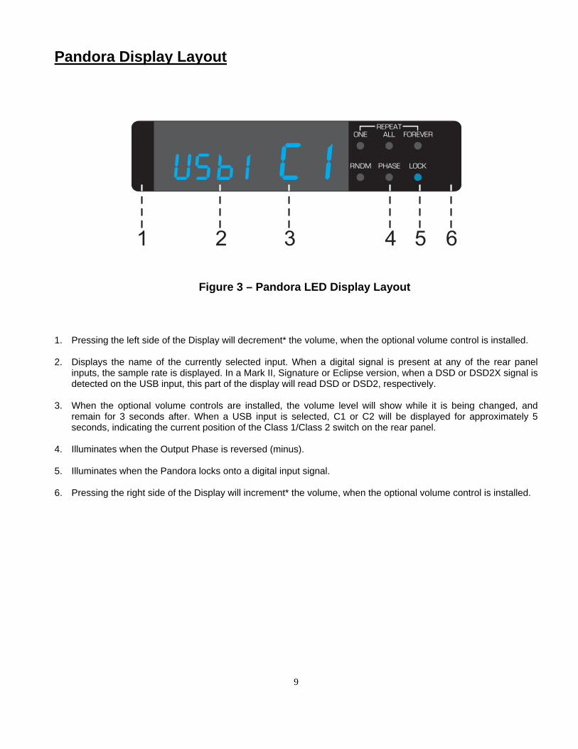
Figure 3 – Pandora LED Display Layout 1. Pressing the left side of the Display will decrement* the volume, when the optional volume control is installed. 2. Displays the name of the currently selected input. When a digital signal is present at any of the rear panel
inputs, the sample rate is displayed. In a Mark II, Signature or Eclipse version, when a DSD or DSD2X signal is detected on the USB input, this part of the display will read DSD or DSD2, respectively.
3. When the optional volume controls are installed, the volume level will show while it is being changed, and
remain for 3 seconds after. When a USB input is selected, C1 or C2 will be displayed for approximately 5 seconds, indicating the current position of the Class 1/Class 2 switch on the rear panel.
4. Illuminates when the Output Phase is reversed (minus). 5. Illuminates when the Pandora locks onto a digital input signal. 6. Pressing the right side of the Display will increment* the volume, when the optional volume control is installed.
9
Rear Panel Layout
ANALOG OUTPUTS
MADE IN USA
AESTHETIX
RS-232 TRIGGER
LEFT
3
RIGHT
12
ON
OFFTOS
COAX
DIGITAL
INPUTS
AES EBU
DIGITAL
INPUTS
USB
Class 2
Class 1
SERIAL NUMBER
0000
1 2 3 4 5 6 7 9 11 1108Left channel outputs 2
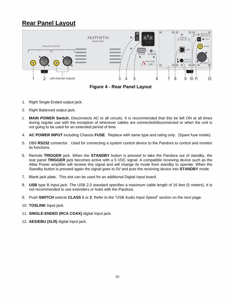
Figure 4 - Rear Panel Layout 1. Right Single-Ended output jack. 2. Right Balanced output jack. 3. MAIN POWER Switch. Disconnects AC to all circuits. It is recommended that this be left ON at all times
during regular use with the exception of whenever cables are connected/disconnected or when the unit is not going to be used for an extended period of time.
4. AC POWER INPUT including Chassis FUSE. Replace with same type and rating only. (Spare fuse inside). 5. DB9 RS232 connector. Used for connecting a system control device to the Pandora to control and monitor
its functions. 6. Remote TRIGGER jack. When the STANDBY button is pressed to take the Pandora out of standby, the
rear panel TRIGGER jack becomes active with a 5 VDC signal. A compatible receiving device such as the Atlas Power amplifier will receive this signal and will change its mode from standby to operate. When the Standby button is pressed again the signal goes to 0V and puts the receiving device into STANDBY mode.
7. Blank jack plate. This slot can be used for an additional Digital Input board. 8. USB type B Input jack. The USB 2.0 standard specifies a maximum cable length of 16 feet (5 meters). It is
not recommended to use extenders or hubs with the Pandora. 9. Push SWITCH selects CLASS 1 or 2. Refer to the “USB Audio Input Speed” section on the next page. 10. TOSLINK Input jack. 11. SINGLE-ENDED (RCA COAX) digital Input jack. 12. AES/EBU (XLR) digital Input jack.
10
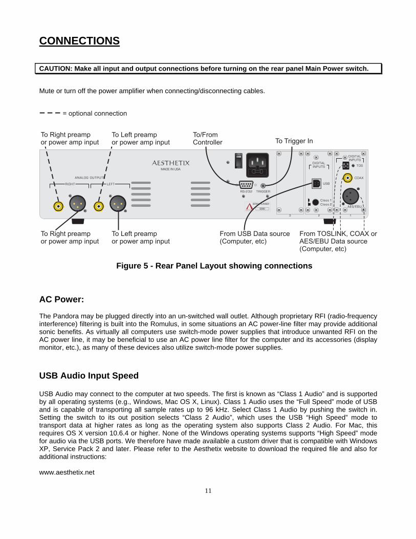
CONNECTIONS CAUTION: Make all input and output connections before turning on the rear panel Main Power switch.
Mute or turn off the power amplifier when connecting/disconnecting cables.
Figure 5 - Rear Panel Layout showing connections AC Power: The Pandora may be plugged directly into an un-switched wall outlet. Although proprietary RFI (radio-frequency interference) filtering is built into the Romulus, in some situations an AC power-line filter may provide additional sonic benefits. As virtually all computers use switch-mode power supplies that introduce unwanted RFI on the AC power line, it may be beneficial to use an AC power line filter for the computer and its accessories (display monitor, etc.), as many of these devices also utilize switch-mode power supplies. USB Audio Input Speed USB Audio may connect to the computer at two speeds. The first is known as “Class 1 Audio” and is supported by all operating systems (e.g., Windows, Mac OS X, Linux). Class 1 Audio uses the “Full Speed” mode of USB and is capable of transporting all sample rates up to 96 kHz. Select Class 1 Audio by pushing the switch in. Setting the switch to its out position selects “Class 2 Audio”, which uses the USB “High Speed” mode to transport data at higher rates as long as the operating system also supports Class 2 Audio. For Mac, this requires OS X version 10.6.4 or higher. None of the Windows operating systems supports “High Speed” mode for audio via the USB ports. We therefore have made available a custom driver that is compatible with Windows XP, Service Pack 2 and later. Please refer to the Aesthetix website to download the required file and also for additional instructions: www.aesthetix.net
11

12
OPERATION Important note: When first installing the Pandora, both it and the computer must first be set up. Once all connections have been made, turn on the rear panel Main Power switch. After the information pages are displayed, the Standby LED will illuminate.
STANDBY
Once the Standby LED is illuminated, press the Standby button once. The Standby LED will blink for approximately 30 seconds, then it will turn off. The display will be on and the Mute LED will be off. Pressing the Standby button when the Standby LED is off will put the Pandora into Standby, at which time the Standby LED will turn on. Place Pandora in standby when not in use.
INPUT Select Buttons Select the desired Input button that corresponds to the rear panel input connector being used.
MUTE Pressing the mute button will alternately mute or unmute the unit. When the mute light is illuminated, the Pandora is muted. When muted, the volume is internally set to zero and the output is shorted to ground.
Volume Control (VC) If the optional volume control is installed, pressing the Up and Down arrows on the hand held remote will raise and lower the volume respectively. Another method is to press the left or right side of the LCD display on the front panel. When connecting the output to a line preamp, *The optional Volume Control in the Romulus Signature VC and Pandora Signature VC operates both in the digital and analog domain for no loss in resolution. The DSD audio format does not allow for any alteration of data, including volume attenuation, mixing, etc. Any form of attenuation requires a conversion to PCM, negating the purpose of DSD. Aesthetix’ pure unadulterated implementation of DSD does not allow the small volume steps implemented with PCM, so the volume steps when listening to DSD files are not as fine as they normally would be when listening to non-DSD files or CD. If it is desirable to have small volume steps when playing DSD files, many computer audio players have the option of converting DSD to PCM, thereby allowing the small volume steps.
DISPLAY
In normal operation, the level setting is displayed and various indicator lights will be illuminated. When the display button is pressed, all LED’s will extinguish. Pressing any button will turn on the display and indicator LED’s for 5 seconds, and then they will extinguish. The only exception is standby, which will always have the Standby light illuminated. Pressing the display button while the display is off, or during the 5 second timeout period, will turn on the display and normal operation will return.
13
Advanced display functionality This unit contains the ability to sense the ambient light level in the room and adjust the display and LEDs accordingly. Additional information about this can be found on the Aesthetix website – www.aesthetix.net REMOTE TRIGGER
The remote trigger control allows the Pandora to control the standby state of a remote unit, such as the Atlas. Power Amplifier. Connect the Trigger Out jack from the Pandora to the Remote Trigger jack on the receiving device. Then turn on the main Power switch of both units. Pressing the Standby button on the Pandora should take the other device out of Standby. Pressing the Standby button on the Pandora once more should put both devices into Standby. The trigger voltage of the receiving device should respond to a constant +5VDC signal. Use a 1/8” (3.5mm) mono plug for this jack. The tip is positive and the sleeve is ground.
RS232
All functions of the Pandora can be controlled and monitored via RS232, using the DB9 connector. As long as the rear panel power switch in turned on, the RS232 circuitry is always active, thus allowing the Pandora to be taken out of STANDBY via RS232.
Memory Buffering
In Pandora/Romulus, SPDIF data (RCA coax, TosLink and AES/EBU XLR) is memory buffered. When the Pandora is being used with video, such as a satellite receiver or DVD player, lip sync issues can occur.
Please refer to technical documentation on the Aesthetix website for information on configuring this feature; www.aesthetix.net SETUP
Configuring your computer No matter what operating system (OS) your computer uses — Apple, Windows, or Linux — you’ll need to set up your computer to perform several different tasks:
• Transferring music to your computer’s hard drive, either by converting the files from your CD collection, commonly called “ripping”, or by purchasing files that are downloaded via the internet.
• Labeling the files you have transferred with the names of the song, artist, album, etc, commonly called “tagging”. (Downloaded files will normally already have the “tags” included.)
• Using a music player program to organize your music collection and play it back.
• Optionally record music selections back onto CDs for playback in your car or other places, commonly called “burning”.
• Optionally transfer part of your music collection to a portable music player.
A few programs can perform all of these functions, for example iTunes (Apple and Windows), J.River Media Center (Windows), and Windows Media Player (Windows). Some users will prefer to use a combination of other specialized programs to perform these functions. An introductory guide to setting up your computer is available at the Aesthetix website at: www.aesthetix.net
Romulus This section provides Instructions and information unique to the Romulus and is intended to be in addition to the Pandora instructions.
Romulus Front Panel Layout
STANDBY INPUT
DISPLAY MUTE
AESTHETIX
EJECT
STOP
ROMULUS
PAUSE PLAY
<SCAN SCAN>
1 4 5 6 8 9 10 12 13 14 15 161132 7
PHASERNDM
ALL FOREVER
LOCK
ONE
REPEAT
743.38
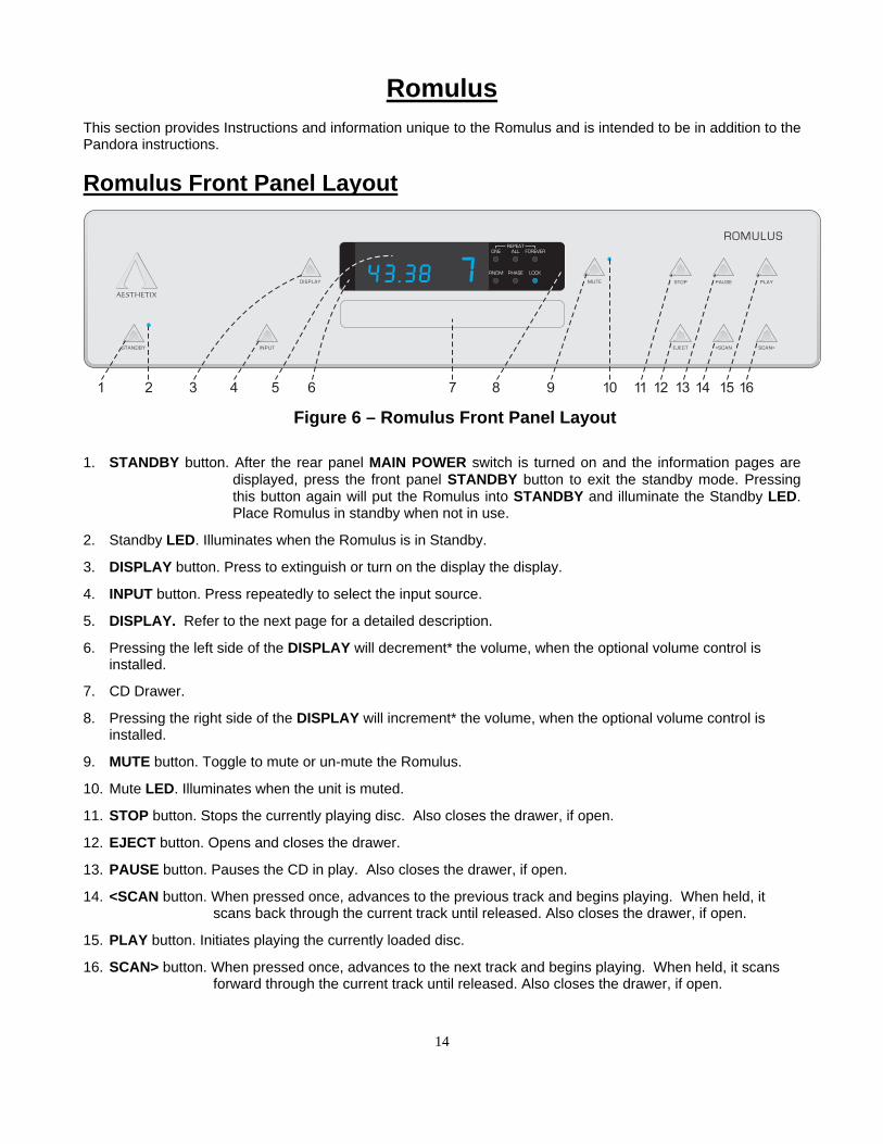
Figure 6 – Romulus Front Panel Layout 1. STANDBY button. After the rear panel MAIN POWER switch is turned on and the information pages are
displayed, press the front panel STANDBY button to exit the standby mode. Pressing this button again will put the Romulus into STANDBY and illuminate the Standby LED. Place Romulus in standby when not in use.
2. Standby LED. Illuminates when the Romulus is in Standby.
3. DISPLAY button. Press to extinguish or turn on the display the display.
4. INPUT button. Press repeatedly to select the input source.
5. DISPLAY. Refer to the next page for a detailed description.
6. Pressing the left side of the DISPLAY will decrement* the volume, when the optional volume control is installed.
7. CD Drawer.
8. Pressing the right side of the DISPLAY will increment* the volume, when the optional volume control is installed.
9. MUTE button. Toggle to mute or un-mute the Romulus.
10. Mute LED. Illuminates when the unit is muted.
11. STOP button. Stops the currently playing disc. Also closes the drawer, if open.
12. EJECT button. Opens and closes the drawer.
13. PAUSE button. Pauses the CD in play. Also closes the drawer, if open.
14. <SCAN button. When pressed once, advances to the previous track and begins playing. When held, it scans back through the current track until released. Also closes the drawer, if open.
15. PLAY button. Initiates playing the currently loaded disc.
16. SCAN> button. When pressed once, advances to the next track and begins playing. When held, it scans forward through the current track until released. Also closes the drawer, if open.
14
Romulus Display Layout
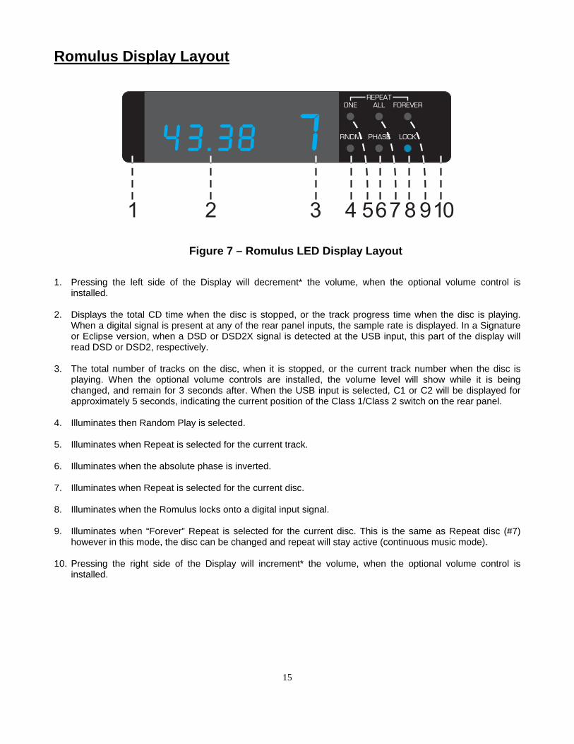
Figure 7 – Romulus LED Display Layout 1. Pressing the left side of the Display will decrement* the volume, when the optional volume control is
installed. 2. Displays the total CD time when the disc is stopped, or the track progress time when the disc is playing.
When a digital signal is present at any of the rear panel inputs, the sample rate is displayed. In a Signature or Eclipse version, when a DSD or DSD2X signal is detected at the USB input, this part of the display will read DSD or DSD2, respectively.
3. The total number of tracks on the disc, when it is stopped, or the current track number when the disc is
playing. When the optional volume controls are installed, the volume level will show while it is being changed, and remain for 3 seconds after. When the USB input is selected, C1 or C2 will be displayed for approximately 5 seconds, indicating the current position of the Class 1/Class 2 switch on the rear panel.
4. Illuminates then Random Play is selected. 5. Illuminates when Repeat is selected for the current track. 6. Illuminates when the absolute phase is inverted. 7. Illuminates when Repeat is selected for the current disc. 8. Illuminates when the Romulus locks onto a digital input signal. 9. Illuminates when “Forever” Repeat is selected for the current disc. This is the same as Repeat disc (#7)
however in this mode, the disc can be changed and repeat will stay active (continuous music mode). 10. Pressing the right side of the Display will increment* the volume, when the optional volume control is
installed.
15
16
Operation When first installing the Romulus, the CD will play by selecting the CD input and pressing play. To use the DAC, both the Romulus and the computer must first be set up. INPUT Pressing the Input button repeatedly will cycle through all inputs. Use this button to select the desired input. The order is: CD, AES1, RCA1, TOS1, USB1. When CD is selected, the Romulus takes a few seconds to read the disc, if installed, so that it can show the disc information in the display. CD CONTROL buttons The STOP button stops the currently playing disc. It closes the drawer if it is open. The EJECT button opens and closes the drawer. The PAUSE button pauses the CD in play as well as closes the drawer if it is open. The <SCAN button, when pressed once, advances to the previous track and begins playing. When held, it scans back through the current track until released. It closes the drawer, if open. The PLAY button initiates playing the currently loaded disc, also closing the drawer if it is open. The SCAN> button, when pressed once, advances to the next track and begins playing. When held, it scans forward through the current track until released. It also closes the drawer if it is open.
17
Appendix A Troubleshooting Guide If the Romulus should function abnormally during operation, please review the items in the following checklist. Please be sure to thoroughly check all other connected components such as speakers, preamplifiers, as well as cables. Symptom Possible Cause(s) Remedy No power or front panel lights and no sound.
Power cable is not inserted 100% into AC input connector.
Ensure that the AC cord is inserted all the way into the Pandora and that the wall outlet is active with the appropriate voltage.
Power Supply fuse(s) is (are) open. Replace with same type and rating ONLY Rear panel fuse is open. Replace with same type and rating ONLY. Circuit breaker is open (AC outlet). Check the AC outlet circuit breaker and reset,
if necessary, or contact your dealer. No audio output. Incorrect source is selected. Look in the display to verify that the correct
source is shown. If it is not, press the Input button repeatedly until it is.
Mute is active Unmute the Pandora. Volume control (if installed) is turned down. Use the hand held remote of the left/right
edges of the display to set the volume accordingly.
Lock light not on. When using a non CD source, verify that the correct input is selected and the source is playing.
LO AC, HI AC The wall AC voltage rose or dropped. Turn off the rear panel AC power switch. Check wall AC voltage. If it fluctuates too much, a power conditioner with Spike and Brown Out protection may be required. Turn on the rear panel AC power switch to reset the unit, then take it out of Standby.
Hot/Warm Normal operation Display Codes If the Romulus displays the following message in the display upon power up: Lo AC or Hi AC. The wall AC voltage rose or dropped. Turn off the rear panel AC power switch. Check wall AC voltage. If it fluctuates too much, a power conditioner with Spike and Brown Out protection may be required. Turn on the rear panel AC power switch to reset the unit, then take it out of Standby. If one of these messages is in the display on power up, the Romulus will not come out of Standby until the error is corrected.

18
Appendix B Specifications USB Audio Input Signal: 44.1, 48, 88.2, 96, 176.4, and 192 kHz 16, 20, and 24 bits. In a MK II, Signature or Eclipse
version, DSD 1x and DSD 2x. S/PDIF Audio Input Signal: 44.1, 48, 88.2, 96, 176.4, and 192 kHz 16, 20, and 24 bits. Maximum Output Level: Balanced: 4.8 V rms without optional volume controls installed. Single-Ended: 2.4 V rms without optional volume controls installed.
Pandora/Romulus with volume controls – the volume setting for standard 2v (SE) / 4v (bal) output is 80 (unity gain). In a Signature or Eclipse version the output level is slightly lower. In this case, the setting for the same output level as a non-volume control unit (unity gain) is 82 (2.5v se, 5v bal).
Output Impedance: 300 ohms balanced. It can drive a balanced impedance of 20K ohms or higher. Recommended Load > 20Kohm balanced, >10Kohm Single-Ended. Impedance: Analog XLR Output Polarity: Pin 1 = Ground. Pin 2 = Non-inverting (Positive). Pin 3 = Inverting (Negative). Frequency Response: 20 Hz - 20 kHz (44.1 kHz sample rate). 20 Hz - 22 kHz (48 kHz sample rate). 20 Hz - 40 kHz (88.2 kHz sample rate). 20 Hz - 44 kHz (96 kHz sample rate). 20 Hz - 80 kHz (176.4 kHz sample rate). 20 Hz - 88 kHz (192 kHz sample rate). Tubes: V401 E83CCS or 12AX7.
V402 6922 (6DJ8). Power Consumption: 25W in standby, 60W locked to an S/PDIF source, 70W with a CD playing. Trigger Output: 1/8” Jack, operates on 5VDC. Dimensions: 17-7/8” W 4-1/4” H 18-1/8" D (45.4 x 10.8 x 46cm). Weight: 30 Lbs. Stand alone (13.6 Kg), 37 Lbs. Boxed with accessories (16.8 Kg). Maximum Operating Internal: 176° F (80° C). Temperature: Room: 122° F (50° C). Fuses: Mains: 2A SB 250V @ 100, 117VAC, 5 x 20mm; 1A SB 250V @ 230 & 245VAC,
5 x 20mm. Power Supply: 250mA SB 250V, 5 x 20mm (x3 in Romulus, x2 in Pandora). Specifications subject to improvement or change without notice.
90 DAY LIMITED WARRANTY TERMS AND CONDITIONS (3 Year optional extended service contract)
1. Aesthetix warrants the product designated herein to be free of manufacturing defects in material and
workmanship, subject to the conditions herein set forth, for a period of 90 days from the date of purchase by the original purchaser. If the purchaser registers the unit with Aesthetix by mailing in the warranty card, together with a copy of the bill of sale, within 14 days of the date of purchase, said purchaser will be registered for an extended service contract. The extended service contract extends the 90 days to a period of 3 years from the date of purchase by the original purchaser or no later than 4 years from the date of shipment to the authorized Aesthetix dealer, whichever comes first. This extension does not apply to tubes. The warranty period for factory tubes does not get extended and therefore remains at 90 days.
2. CONDITIONS This warranty is subject to the following conditions and limitations. The warranty is void and
inapplicable if the product has been used or handled other than in accordance with the instructions in the owner's manual, abused or misused, damaged by accident or neglect or in being transported, or the defect is due to the product being repaired or tampered with or modified by anyone other than Aesthetix. The product must be packed and returned to Aesthetix by the customer at his or her sole expense. A written description of the defect and a photocopy of the original purchase receipt must accompany a returned product. This receipt must clearly list model and serial number, the date of purchase, the name and address of the purchaser and authorized dealer and the purchase price. Aesthetix reserves the right to modify the design of any product without obligation to purchasers of previously manufactured products and to change the prices or specifications of any product without notice or obligation to any person.
3. REMEDY In the event the above product fails to meet the warranty, and the above conditions have been met,
the purchaser's sole remedy under the limited warranty shall be to return the product to Aesthetix where the defect will be rectified without charge for parts or labor. Aesthetix reserves the right to inspect any product that is the subject of any warranty claim prior to repairing it. Final determination of warranty coverage lies solely with Aesthetix.
4. LIMITED TO ORIGINAL PURCHASER This warranty is for the sole benefit of the original purchaser of the covered product and shall not
be transferred to a subsequent purchaser of the product. 5. DURATION OF WARRANTY This warranty expires 90 days after the date of original purchase. If Aesthetix receives the warranty
registration card, this period is extended to the third anniversary of the date of purchase or no later that the fourth anniversary of the shipment to the authorized Aesthetix dealer, whichever comes first. This extension does not apply to tubes. The warranty period for factory tubes does not get extended and therefore remains at 90 days.
6. MISCELLANEOUS ANY IMPLIED WARRANTIES RELATING TO THE ABOVE PRODUCT SHALL BE LIMITED TO
THE DURATION OF THIS WARRANTY. THE WARRANTY DOES NOT EXTEND TO ANY INCIDENTAL OR CONSEQUENTIAL COSTS OR DAMAGES TO THE PURCHASER. Some states do not allow limitations on how long an implied warranty lasts or an exclusion or limitation of incidental or consequential damages, so the above limitations or exclusions may not apply to you. This Warranty gives you specific legal rights, and you may also have other rights which vary from state to state.
7. WARRANTY OUTSIDE THE USA Aesthetix has formal distribution in many of the countries of the free world, in each country the
Aesthetix importer has contractually accepted the responsibility for product warranty. Warranty should normally be obtained from the importing dealer or distributor from whom you obtain your product.
19 Rev 2.33 2020-03-12


![Romulus - NISTRomulus-M follows the general construction of MRAE called SIV [38]. Romulus-M reuses the components of Romulus-N as much as possible, and Romulus-M is simply obtained](https://img.pdfslide.net/doc/110x75/611904b69cf9ca7cb67fc5b0/romulus-nist-romulus-m-follows-the-general-construction-of-mrae-called-siv-38.jpg)