Embed Size (px)
Citation preview
PantherPantherPantherPanther Fan Coil Units Fan Coil Units Fan Coil Units Fan Coil Units
Installation, Operation and Maintenance InstructionsInstallation, Operation and Maintenance InstructionsInstallation, Operation and Maintenance InstructionsInstallation, Operation and Maintenance Instructions....
Dunham-Bush Ltd, Downley Road, Havant, Hants PO9 2JD
Tel. 023 9247 7700 Fax. 023 9245 3601 PDSPDSPDSPDS----1200120012001200----FFFF----0202020222226666----00004444
(Global) www.dunham-bush.com Document Part No: 126-000-001
(UK) www.dunham-bush.co.uk Date : April 2013
INTRODUCTIONINTRODUCTIONINTRODUCTIONINTRODUCTION
This booklet provides guidance to identify, handle,
install and commission Dunham-Bush Panther fan coil
units as well as guidance for operation and
maintenance.
These instructions are to be read in These instructions are to be read in These instructions are to be read in These instructions are to be read in
conjunction with the wiring diagramconjunction with the wiring diagramconjunction with the wiring diagramconjunction with the wiring diagram suppl suppl suppl supplied ied ied ied
with the unitwith the unitwith the unitwith the unit....
The instructions apply to units from the standard
range only. Please study the instructions carefully
before commencing any installation work.
IDENTIFICATIONIDENTIFICATIONIDENTIFICATIONIDENTIFICATION
The fan coil unit serial number, description, figure
number (size) are displayed on a label found on the
unit discharge plenum. If specified, a stencil reference
may also be marked on the discharge plenum for on-
site identification.
DESCRIPTIONDESCRIPTIONDESCRIPTIONDESCRIPTION
Dunham-Bush Panther fan coil unit comprises a self-
finished galvanised sheet steel casing with multiple
access panels to each part of the fan coil unit,
including fans, motors, air filter, dual purpose
heating/cooling coil, electrical connections box and
discharge plenum.
STANDARD RANGE MODELS & SIZESSTANDARD RANGE MODELS & SIZESSTANDARD RANGE MODELS & SIZESSTANDARD RANGE MODELS & SIZES
Panther is a horizontal basic chassis fan coil,
available in seven sizes, figs 1 to 7 inclusive Each size
is available with octagonal or rectangular discharge
plenums, as well as optional inlet spigot plenums. Panthers are available with AC motors or EC/DC
motors.
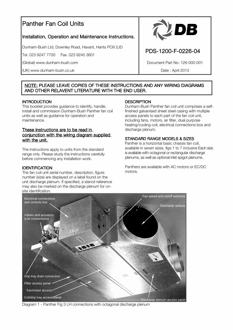
Diagram 1 - Panther Fig 3 LH connections with octagonal discharge plenum
NOTE:NOTE:NOTE:NOTE: PLEASE LEAVE COPIES OF THESE INSTRUCTIONS AND ANY WIRING DI PLEASE LEAVE COPIES OF THESE INSTRUCTIONS AND ANY WIRING DI PLEASE LEAVE COPIES OF THESE INSTRUCTIONS AND ANY WIRING DI PLEASE LEAVE COPIES OF THESE INSTRUCTIONS AND ANY WIRING DIAGRAMS AGRAMS AGRAMS AGRAMS
AND OTHER RELAVENT LITERATURE WITH THE END USER.AND OTHER RELAVENT LITERATURE WITH THE END USER.AND OTHER RELAVENT LITERATURE WITH THE END USER.AND OTHER RELAVENT LITERATURE WITH THE END USER.
Electrical connections and controls box
Fan speed and on/off switches
Discharge spigots
Drip tray drain connection
Valves and actuators (coil connections)
Coil/drip tray access panel
Filter access panel
Fan/motor access
Discharge plenum access panel
Page 2 of 12
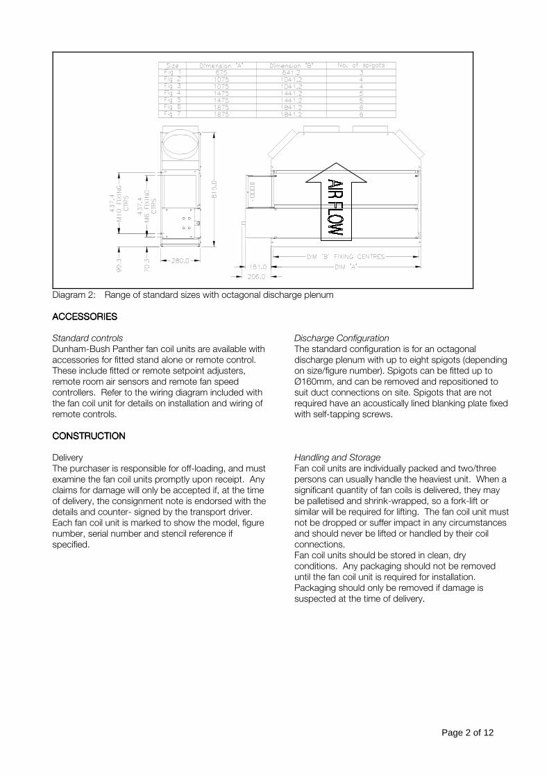
Diagram 2: Range of standard sizes with octagonal discharge plenum
ACCESSORIESACCESSORIESACCESSORIESACCESSORIES
Standard controls
Dunham-Bush Panther fan coil units are available with
accessories for fitted stand alone or remote control.
These include fitted or remote setpoint adjusters,
remote room air sensors and remote fan speed
controllers. Refer to the wiring diagram included with
the fan coil unit for details on installation and wiring of
remote controls.
Discharge Configuration
The standard configuration is for an octagonal
discharge plenum with up to eight spigots (depending
on size/figure number). Spigots can be fitted up to
Ø160mm, and can be removed and repositioned to
suit duct connections on site. Spigots that are not
required have an acoustically lined blanking plate fixed
with self-tapping screws.
CONSTRUCTIONCONSTRUCTIONCONSTRUCTIONCONSTRUCTION
Delivery
The purchaser is responsible for off-loading, and must
examine the fan coil units promptly upon receipt. Any
claims for damage will only be accepted if, at the time
of delivery, the consignment note is endorsed with the
details and counter- signed by the transport driver.
Each fan coil unit is marked to show the model, figure
number, serial number and stencil reference if
specified.
Handling and Storage
Fan coil units are individually packed and two/three
persons can usually handle the heaviest unit. When a
significant quantity of fan coils is delivered, they may
be palletised and shrink-wrapped, so a fork-lift or
similar will be required for lifting. The fan coil unit must
not be dropped or suffer impact in any circumstances
and should never be lifted or handled by their coil
connections.
Fan coil units should be stored in clean, dry
conditions. Any packaging should not be removed
until the fan coil unit is required for installation.
Packaging should only be removed if damage is
suspected at the time of delivery.
Page 3 of 12
WARNINGWARNINGWARNINGWARNING: : : : PantherPantherPantherPanther fan coil units are designed with fan coil units are designed with fan coil units are designed with fan coil units are designed with minimal sharp edges on the chassis. Some internal minimal sharp edges on the chassis. Some internal minimal sharp edges on the chassis. Some internal minimal sharp edges on the chassis. Some internal
components on the fan coil may have sharp edges. Care must be taken when handling the product; components on the fan coil may have sharp edges. Care must be taken when handling the product; components on the fan coil may have sharp edges. Care must be taken when handling the product; components on the fan coil may have sharp edges. Care must be taken when handling the product;
protective gloves should be worn.protective gloves should be worn.protective gloves should be worn.protective gloves should be worn.
FIGUREFIGUREFIGUREFIGURE 1111 2222 3333 4444 5555 6666 7777
Dry mass of basic unit with discharge
spigot plenum only (kg)
37 51 56 70 75 92 96
Table 1: Approximate masses of Panther fan coil units
INSTALLATIONINSTALLATIONINSTALLATIONINSTALLATION
General
Before removing any packaging, check the identity of
the fan coil unit against the stencil reference marked
on the access panel. Packaging should be retained to
protect the fan coil unit from damage by other works
after installation.
Fitting
1. Prepare drop rods to accept the fan coil. M6,
M8 or M10 drop rods are recommended, with
appropriate washers. Refer to diagram 2 for
positions of fixings.
2. Suspend the fan coil unit and ensure it is level in
both directions. Use a spirit level on the casing.
(The drip tray is graded internally to ensure
drainage of condensate).
3. Connect ductwork to the fan coil unit. Flexible
duct connections are recommended where
sheet metal ductwork is used. Do not suspend
any ductwork from the fan coil unit alone. Refer
to diagram 4 for spigot positions.
4. Connect pipework as shown in Diagram 4.
5. Connect a suitable drain to the drip tray.
6. Connect electrical supply and control
accessories as shown in wiring diagrams
enclosed with the fan coil unit.
7. After filling the hot and chilled water systems,
check for leaks (refer to Commissioning).
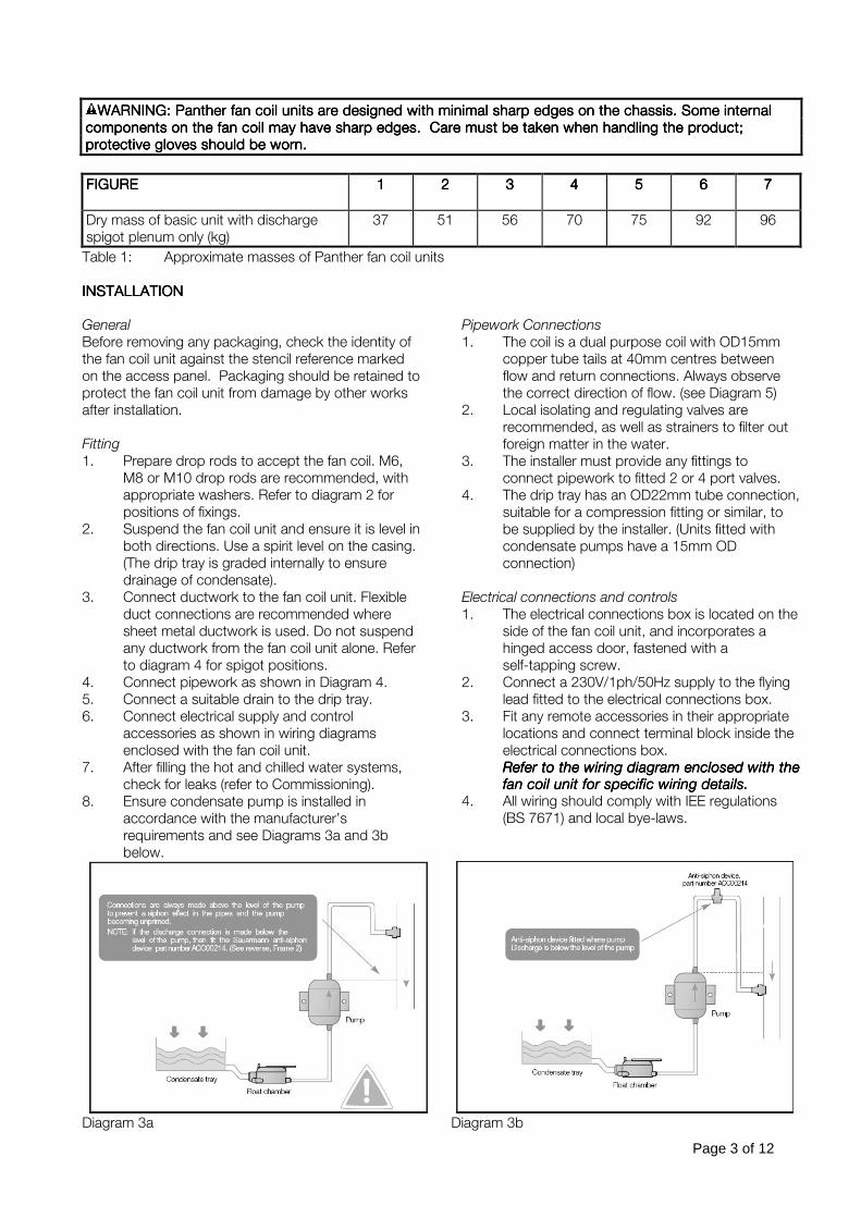
8. Ensure condensate pump is installed in
accordance with the manufacturer’s
requirements and see Diagrams 3a and 3b
below.
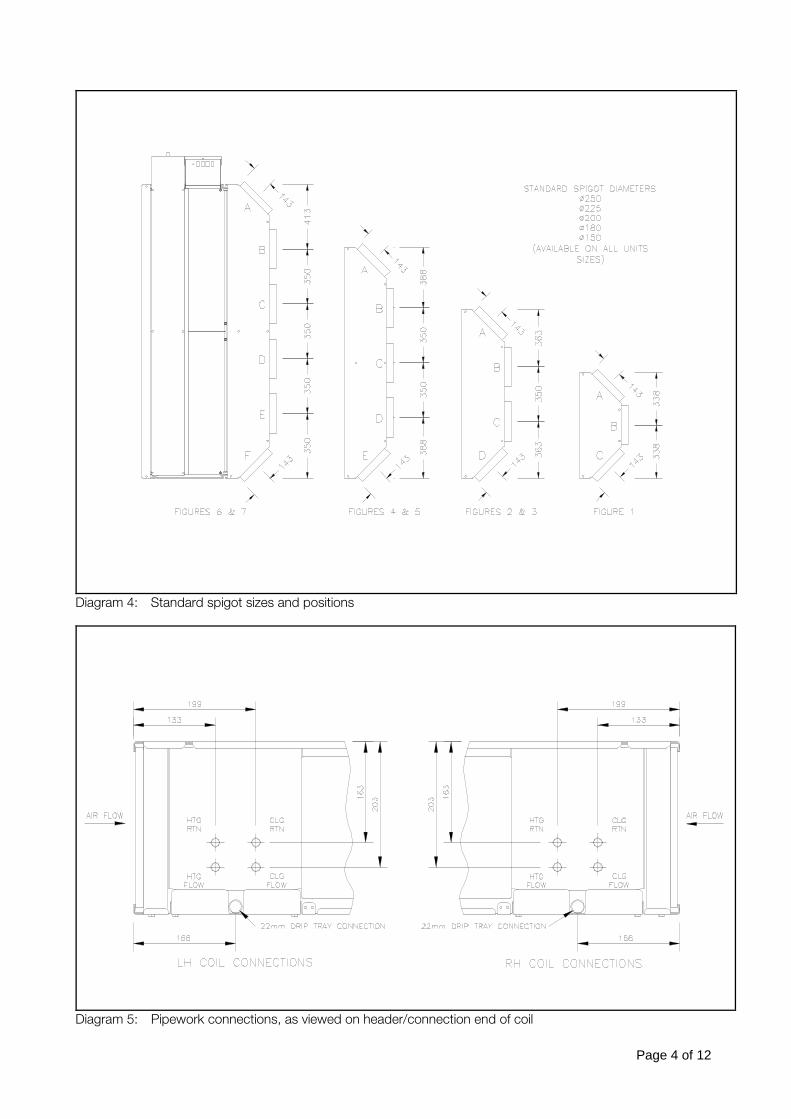
Pipework Connections
1. The coil is a dual purpose coil with OD15mm
copper tube tails at 40mm centres between
flow and return connections. Always observe
the correct direction of flow. (see Diagram 5)
2. Local isolating and regulating valves are
recommended, as well as strainers to filter out
foreign matter in the water.
3. The installer must provide any fittings to
connect pipework to fitted 2 or 4 port valves.
4. The drip tray has an OD22mm tube connection,
suitable for a compression fitting or similar, to
be supplied by the installer. (Units fitted with
condensate pumps have a 15mm OD
connection)
Electrical connections and controls
1. The electrical connections box is located on the
side of the fan coil unit, and incorporates a
hinged access door, fastened with a
self-tapping screw.
2. Connect a 230V/1ph/50Hz supply to the flying
lead fitted to the electrical connections box.
3. Fit any remote accessories in their appropriate
locations and connect terminal block inside the
electrical connections box. Refer to the wiring diagram enclosed with the Refer to the wiring diagram enclosed with the Refer to the wiring diagram enclosed with the Refer to the wiring diagram enclosed with the fan coil unifan coil unifan coil unifan coil unit for specific wiring details.t for specific wiring details.t for specific wiring details.t for specific wiring details.
4. All wiring should comply with IEE regulations
(BS 7671) and local bye-laws.
Diagram 3a Diagram 3b
Page 4 of 12
Diagram 4: Standard spigot sizes and positions
Diagram 5: Pipework connections, as viewed on header/connection end of coil
Page 5 of 12
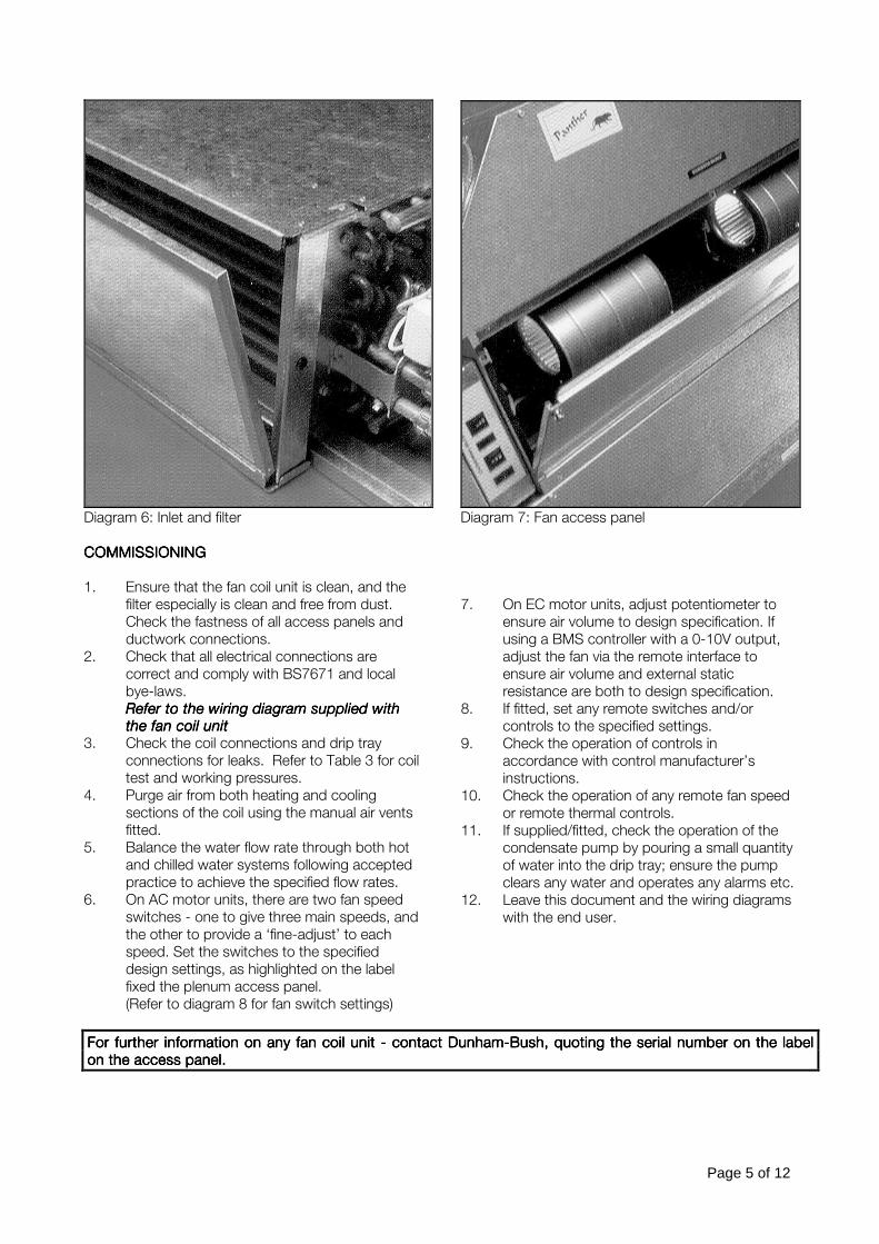
Diagram 6: Inlet and filter Diagram 7: Fan access panel
COMMISSIONINGCOMMISSIONINGCOMMISSIONINGCOMMISSIONING
1. Ensure that the fan coil unit is clean, and the
filter especially is clean and free from dust.
Check the fastness of all access panels and
ductwork connections.
2. Check that all electrical connections are
correct and comply with BS7671 and local
bye-laws. Refer to the wiring diagram supplied with Refer to the wiring diagram supplied with Refer to the wiring diagram supplied with Refer to the wiring diagram supplied with the fan coil unitthe fan coil unitthe fan coil unitthe fan coil unit
3. Check the coil connections and drip tray
connections for leaks. Refer to Table 3 for coil
test and working pressures.
4. Purge air from both heating and cooling
sections of the coil using the manual air vents
fitted.
5. Balance the water flow rate through both hot
and chilled water systems following accepted
practice to achieve the specified flow rates.
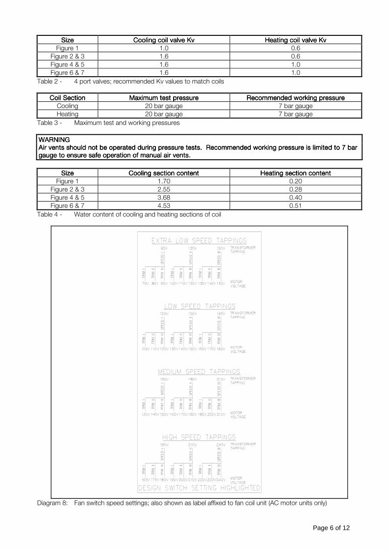
6. On AC motor units, there are two fan speed
switches - one to give three main speeds, and
the other to provide a ‘fine-adjust’ to each
speed. Set the switches to the specified
design settings, as highlighted on the label
fixed the plenum access panel.
(Refer to diagram 8 for fan switch settings)
7. On EC motor units, adjust potentiometer to
ensure air volume to design specification. If
using a BMS controller with a 0-10V output,
adjust the fan via the remote interface to
ensure air volume and external static
resistance are both to design specification.
8. If fitted, set any remote switches and/or
controls to the specified settings.
9. Check the operation of controls in
accordance with control manufacturer’s
instructions.
10. Check the operation of any remote fan speed
or remote thermal controls.
11. If supplied/fitted, check the operation of the
condensate pump by pouring a small quantity
of water into the drip tray; ensure the pump
clears any water and operates any alarms etc.
12. Leave this document and the wiring diagrams
with the end user.
For further information on any fan coil unit For further information on any fan coil unit For further information on any fan coil unit For further information on any fan coil unit ---- contact Dunham contact Dunham contact Dunham contact Dunham----Bush, quoting the serial number on the label Bush, quoting the serial number on the label Bush, quoting the serial number on the label Bush, quoting the serial number on the label
on the access panel.on the access panel.on the access panel.on the access panel.
Page 6 of 12
SizeSizeSizeSize Cooling coil valve KvCooling coil valve KvCooling coil valve KvCooling coil valve Kv Heating coil valve KvHeating coil valve KvHeating coil valve KvHeating coil valve Kv
Figure 1 1.0 0.6
Figure 2 & 3 1.6 0.6
Figure 4 & 5 1.6 1.0
Figure 6 & 7 1.6 1.0
Table 2 - 4 port valves; recommended Kv values to match coils
Coil SectionCoil SectionCoil SectionCoil Section Maximum test pressureMaximum test pressureMaximum test pressureMaximum test pressure Recommended working pressureRecommended working pressureRecommended working pressureRecommended working pressure
Cooling 20 bar gauge 7 bar gauge
Heating 20 bar gauge 7 bar gauge
Table 3 - Maximum test and working pressures
WARNINGWARNINGWARNINGWARNING
Air vents should not be operated during pressure tests. Recommended working pressure is limited to 7 Air vents should not be operated during pressure tests. Recommended working pressure is limited to 7 Air vents should not be operated during pressure tests. Recommended working pressure is limited to 7 Air vents should not be operated during pressure tests. Recommended working pressure is limited to 7 bar bar bar bar
gaugegaugegaugegauge to ensure safe operation of manual air vents. to ensure safe operation of manual air vents. to ensure safe operation of manual air vents. to ensure safe operation of manual air vents.
SizeSizeSizeSize Cooling section contentCooling section contentCooling section contentCooling section content Heating section contentHeating section contentHeating section contentHeating section content
Figure 1 1.70 0.20
Figure 2 & 3 2.55 0.28
Figure 4 & 5 3.68 0.40
Figure 6 & 7 4.53 0.51
Table 4 - Water content of cooling and heating sections of coil
Diagram 8: Fan switch speed settings; also shown as label affixed to fan coil unit (AC motor units only)
Page 7 of 12
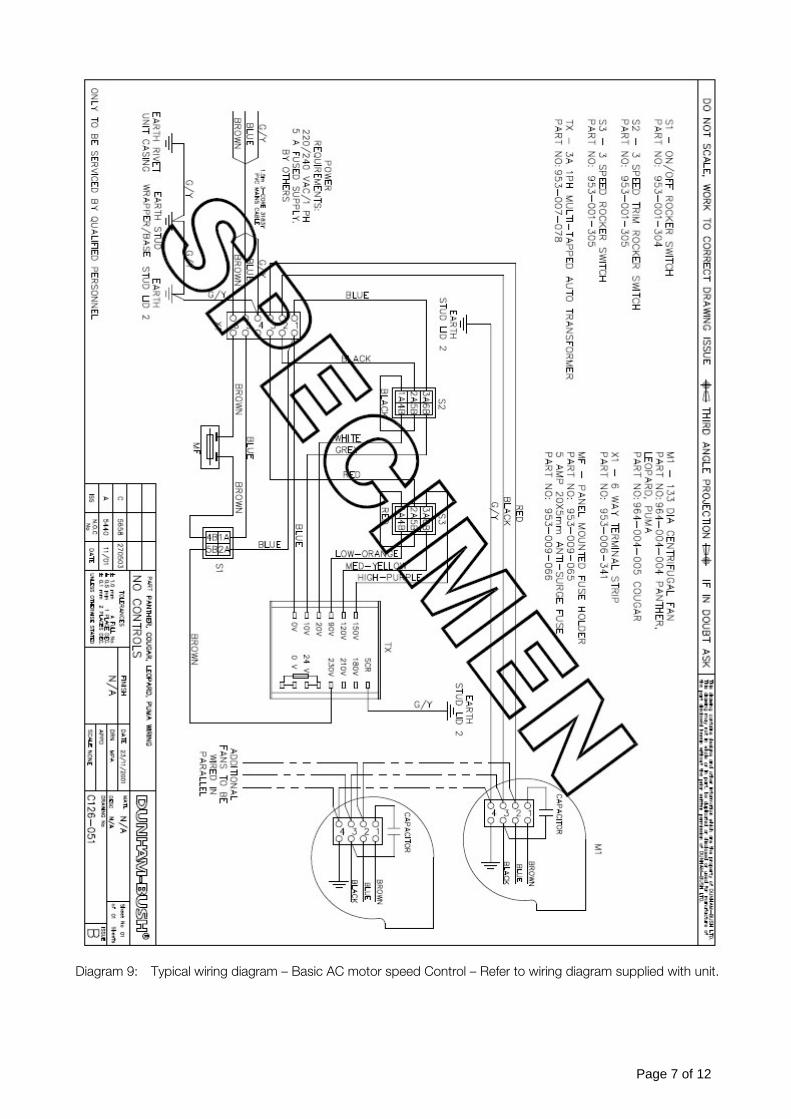
Diagram 9: Typical wiring diagram – Basic AC motor speed Control – Refer to wiring diagram supplied with unit.
Page 8 of 12
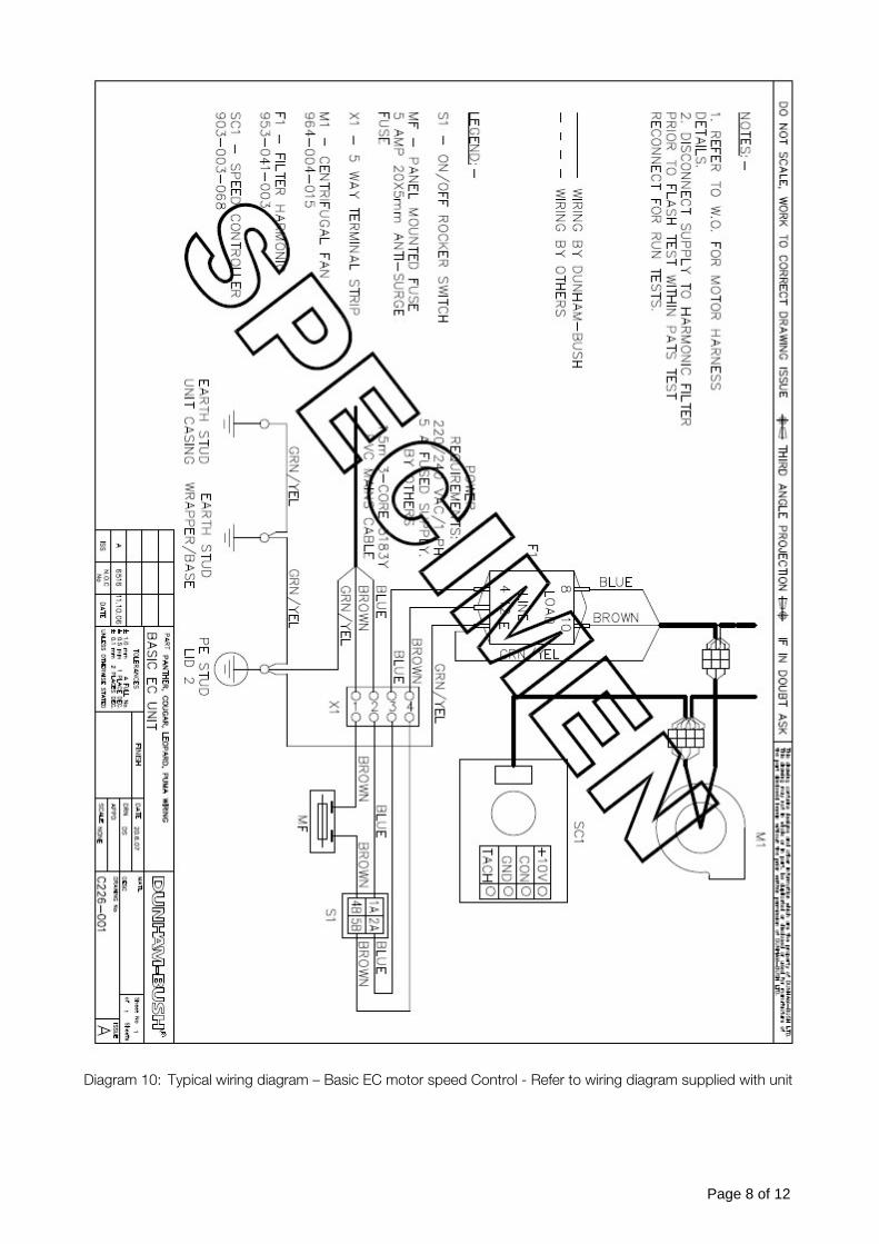
Diagram 10: Typical wiring diagram – Basic EC motor speed Control - Refer to wiring diagram supplied with unit
Page 9 of 12
OPERATIONOPERATIONOPERATIONOPERATION
Panther fan coils provide cooling and heating of air
when used in conjunction with chilled water and/or
low temperature hot water systems. They are
designed for mounting in a ceiling or roof void,
connected to ductwork.
When running, the fan draws air from the room and
the primary air supply, through an inlet filter and over
the finned tubes of a heating/cooling coil. The air is
then discharged through spigots, along ductwork
and through grilles or diffusers to the room space.
Alternative options include chilled water cooling only,
and intake through ductwork and spigots.
Fans normally run continuously, with an automatic
control system varying the flow rates of chilled water
and hot water through the coil (waterside control),
thus varying the cooling and heating outputs.
Depending upon the particular type of controls fitted,
user control is provided by fan speed switches and/or
temperature control.
CONTROLSCONTROLSCONTROLSCONTROLS
Panther fan coil units are fitted with a waterside
control system, which typically comprises the
following elements :-
Fitted fan on/off switch
Fan speed change switches (AC motor units)
Fan speed potentiometer (EC motor units)
Fan coil controller
Return air sensor
Valve actuators (Two or four port valves)
Additional optional accessories include :-
Remote room air sensor
Remote setpoint adjuster
Remote fan on/off and speed switches
Fitted relays for master/slave or BMS control
Dunham-Bush also fit non-standard controls supplied
by others; refer to the wiring diagram supplied with
the unit.
CLEANING CLEANING CLEANING CLEANING
Cleaning and maintenance must be carried out by
competent persons Inspection
The frequency of cleaning and inspection depends
upon the conditions in which the fan coil unit
operates. Initially, it is suggested that the air filter and
drip tray are inspected after 6-8 weeks normal
operation.
Access
There are four access panels - filter, drip tray/coil,
fans/motors and discharge plenum. All access panels
can be opened by removing screws and turning
quarter-turn fasteners.
The filter can be removed by sliding it out from its
mounting on the fan coil inlet, or from below by
removing its access panel. Cleaning
Panther fan coil units are fitted with an air filter on the
inlet. The filter comprises a filter frame, mesh
and filter material that is retained with wire clips into
the filter frame. The filter can be removed by either sliding the filter sideways, out of its channels on the
unit chassis or by pushing and tilting the filter out of
the channels, as shown in diagrams 11 to 14
overleaf.
1. Air filters can be cleaned by tapping out
excess dust and washing in warm water (up to
40°C), using detergent if necessary. The filter
must be rinsed and allow to dry naturally
before replacing. Do not use a vacuum
cleaner, as it can damage the filter media.
Filters should be replaced after approximately
20 washes.
2. The drip tray can be cleaned with warm, soapy
water. Ensure the drip tray drains freely.
3. If a condensate pump is fitted, check any
sensors are clean and wiped dry. Test the
operation of the pump by pouring clean water
into the drip tray.
Because the air filter retains most of the dusty
particles, it will only be necessary to clean the fans,
motors and coil annually. An industrial vacuum
cleaner can be used to clean the inside of the fan
coil, in particular the coil and fans, with the air being
sucked through the coil in the opposite direction to
normal air flow. All accessible surfaces can be
cleaned with a cloth.
Page 10 of 12
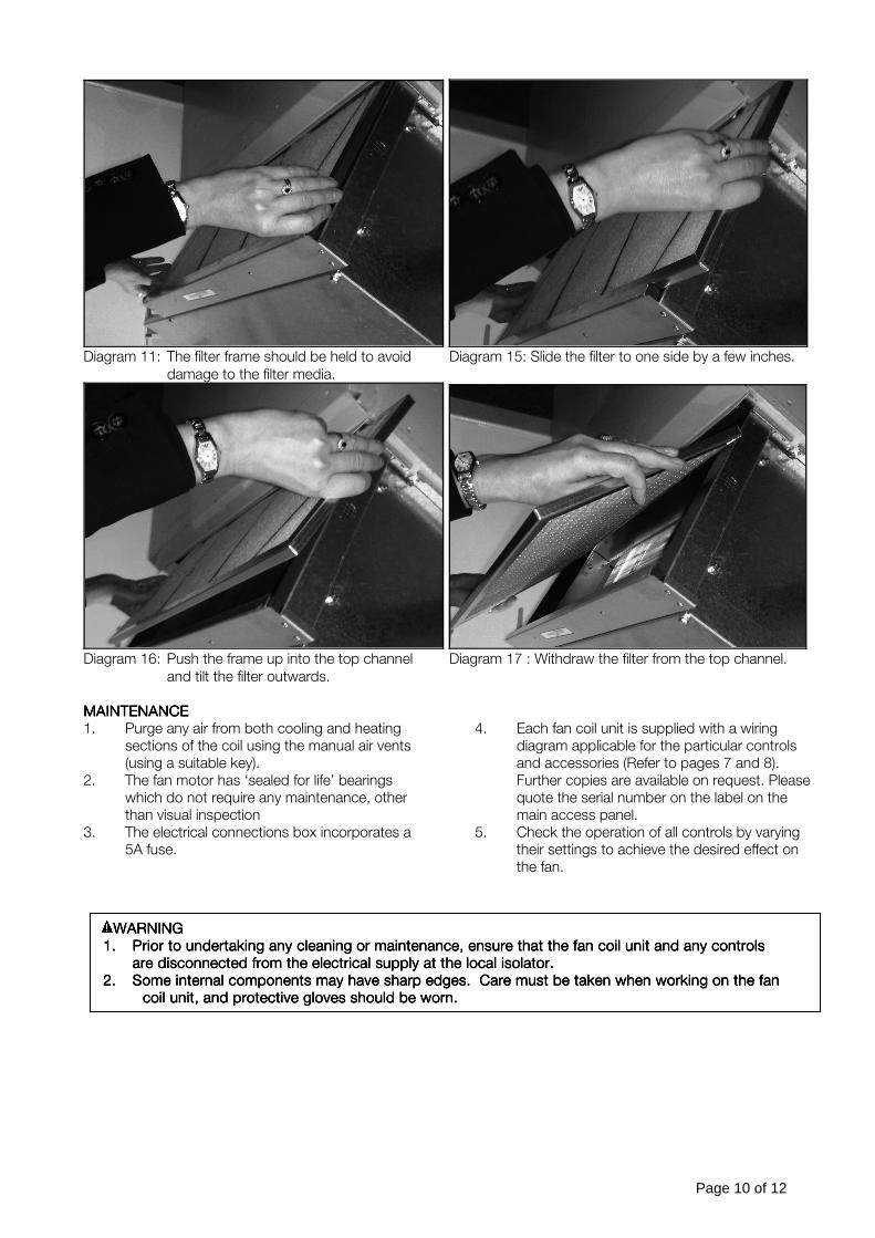
Diagram 11: The filter frame should be held to avoid Diagram 15: Slide the filter to one side by a few inches.
damage to the filter media.
Diagram 16: Push the frame up into the top channel Diagram 17 : Withdraw the filter from the top channel.
and tilt the filter outwards.
MAINTENANCEMAINTENANCEMAINTENANCEMAINTENANCE
1. Purge any air from both cooling and heating
sections of the coil using the manual air vents
(using a suitable key).
2. The fan motor has ‘sealed for life’ bearings
which do not require any maintenance, other
than visual inspection
3. The electrical connections box incorporates a
5A fuse.
4. Each fan coil unit is supplied with a wiring
diagram applicable for the particular controls
and accessories (Refer to pages 7 and 8).
Further copies are available on request. Please
quote the serial number on the label on the
main access panel.
5. Check the operation of all controls by varying
their settings to achieve the desired effect on
the fan.
WARNINGWARNINGWARNINGWARNING
1.1.1.1. PPPPrior to undertaking any cleaning or maintenance, ensure that the fan coil unit andrior to undertaking any cleaning or maintenance, ensure that the fan coil unit andrior to undertaking any cleaning or maintenance, ensure that the fan coil unit andrior to undertaking any cleaning or maintenance, ensure that the fan coil unit and any controls any controls any controls any controls
are disconnected from the electrical supply at the local isolator.are disconnected from the electrical supply at the local isolator.are disconnected from the electrical supply at the local isolator.are disconnected from the electrical supply at the local isolator.
2.2.2.2. Some internal components may have sharp edges. Care must bSome internal components may have sharp edges. Care must bSome internal components may have sharp edges. Care must bSome internal components may have sharp edges. Care must be taken when working on the fane taken when working on the fane taken when working on the fane taken when working on the fan
coil unit, and protective gloves should be worn.coil unit, and protective gloves should be worn.coil unit, and protective gloves should be worn.coil unit, and protective gloves should be worn.
Page 11 of 12
Page 12 of 12
SPARES/SERVICESPARES/SERVICESPARES/SERVICESPARES/SERVICE
PLEASE WRPLEASE WRPLEASE WRPLEASE WRITE THE DETAILS OF THE UNIT HERE.ITE THE DETAILS OF THE UNIT HERE.ITE THE DETAILS OF THE UNIT HERE.ITE THE DETAILS OF THE UNIT HERE.
These details will be required when ordering spares for you Dunham-Bush Panther Fancoil Unit
UNIT TYPE AND MODEL INFORMATION
SERIAL NUMBER
DATE OF INSTALLATION
Spare parts/service – Please contact our office, contact information shown below.
Manufacturer reserves the right to change any product specification without notice.Manufacturer reserves the right to change any product specification without notice.Manufacturer reserves the right to change any product specification without notice.Manufacturer reserves the right to change any product specification without notice.
Dunham-Bush Ltd, Downley Road, Havant, Hants, PO9 2JD
Sales and Technical Support Spare Parts and Service
Tel: 023 9247 7700 Fax: 023 9245 3601 Tel: 023 9247 7700 Fax: 023 9245 3601
Email: [email protected] Email: [email protected]