Embed Size (px)
Citation preview
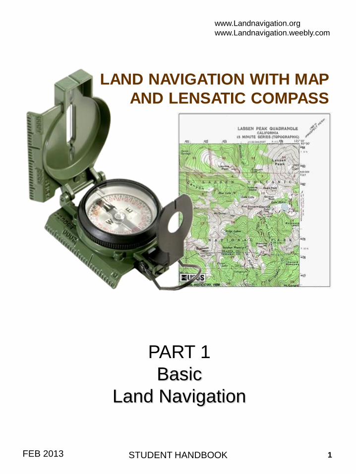
LAND NAVIGATION WITH MAP
AND LENSATIC COMPASS
PART 1
Basic
Land Navigation
STUDENT HANDBOOKFEB 2013
www.Landnavigation.org
www.Landnavigation.weebly.com
1
PART 1 Basic Land Navigation
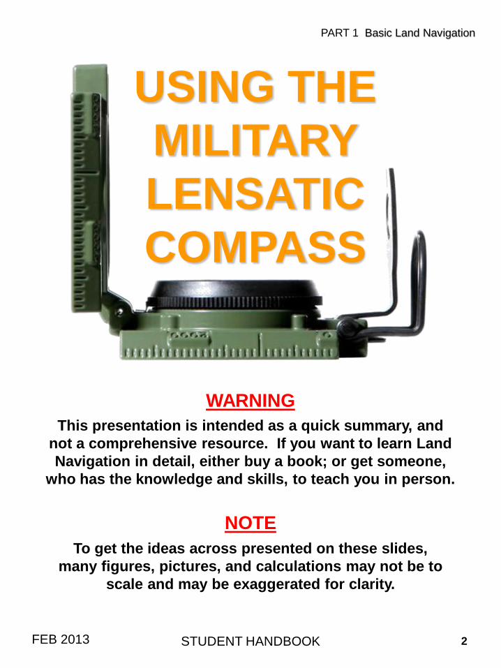
This presentation is intended as a quick summary, and
not a comprehensive resource. If you want to learn Land
Navigation in detail, either buy a book; or get someone,
who has the knowledge and skills, to teach you in person.
WARNING
NOTE
To get the ideas across presented on these slides,
many figures, pictures, and calculations may not be to
scale and may be exaggerated for clarity.
USING THE
MILITARY
LENSATIC
COMPASS
STUDENT HANDBOOK 2FEB 2013
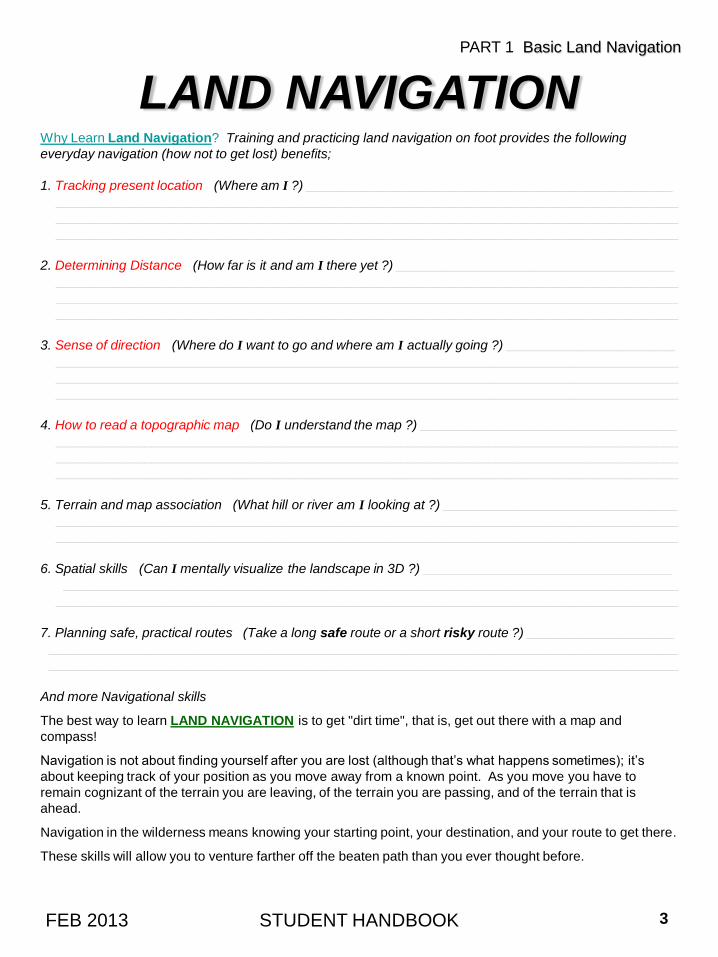
LAND NAVIGATIONWhy Learn Land Navigation? Training and practicing land navigation on foot provides the following
everyday navigation (how not to get lost) benefits;
1. Tracking present location (Where am I ?) __________________________________________________
_____________________________________________________________________________________
_____________________________________________________________________________________
_____________________________________________________________________________________
2. Determining Distance (How far is it and am I there yet ?) ______________________________________
_____________________________________________________________________________________
_____________________________________________________________________________________
_____________________________________________________________________________________
3. Sense of direction (Where do I want to go and where am I actually going ?) _______________________
_____________________________________________________________________________________
_____________________________________________________________________________________
_____________________________________________________________________________________
4. How to read a topographic map (Do I understand the map ?) ___________________________________
_____________________________________________________________________________________
_____________________________________________________________________________________
_____________________________________________________________________________________
5. Terrain and map association (What hill or river am I looking at ?) ________________________________
_____________________________________________________________________________________
_____________________________________________________________________________________
6. Spatial skills (Can I mentally visualize the landscape in 3D ?) __________________________________
____________________________________________________________________________________
_____________________________________________________________________________________
7. Planning safe, practical routes (Take a long safe route or a short risky route ?) ____________________
______________________________________________________________________________________
______________________________________________________________________________________
And more Navigational skills
The best way to learn LAND NAVIGATION is to get "dirt time", that is, get out there with a map and
compass!
Navigation is not about finding yourself after you are lost (although that’s what happens sometimes); it’s
about keeping track of your position as you move away from a known point. As you move you have to
remain cognizant of the terrain you are leaving, of the terrain you are passing, and of the terrain that is
ahead.
Navigation in the wilderness means knowing your starting point, your destination, and your route to get there .
These skills will allow you to venture farther off the beaten path than you ever thought before.
PART 1 Basic Land Navigation
STUDENT HANDBOOK 3FEB 2013
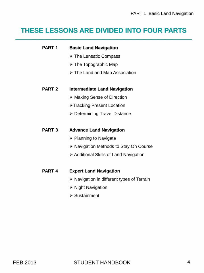
THESE LESSONS ARE DIVIDED INTO FOUR PARTS________________________________________________________________________________________________________
PART 1 Basic Land Navigation
The Lensatic Compass
The Topographic Map
The Land and Map Association
PART 2 Intermediate Land Navigation
Making Sense of Direction
Tracking Present Location
Determining Travel Distance
PART 3 Advance Land Navigation
Planning to Navigate
Navigation Methods to Stay On Course
Additional Skills of Land Navigation
PART 4 Expert Land Navigation
Navigation in different types of Terrain
Night Navigation
Sustainment
PART 1 Basic Land Navigation
STUDENT HANDBOOK 4FEB 2013
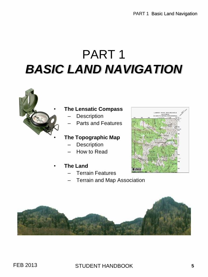
PART 1
BASIC LAND NAVIGATION
• The Lensatic Compass
– Description
– Parts and Features
• The Topographic Map
– Description
– How to Read
• The Land
– Terrain Features
– Terrain and Map Association
PART 1 Basic Land Navigation
STUDENT HANDBOOK 5FEB 2013
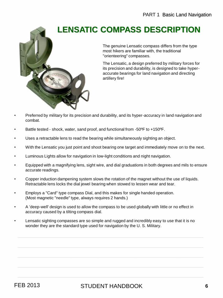
The genuine Lensatic compass differs from the type
most hikers are familiar with, the traditional
"orienteering" compasses.
The Lensatic, a design preferred by military forces for
its precision and durability, is designed to take hyper-
accurate bearings for land navigation and directing
artillery fire!
LENSATIC COMPASS DESCRIPTION
STUDENT HANDBOOK 6FEB 2013
PART 1 Basic Land Navigation
• Preferred by military for its precision and durability, and its hyper-accuracy in land navigation and
combat.
• Battle tested - shock, water, sand proof, and functional from -50ºF to +150ºF.
• Uses a retractable lens to read the bearing while simultaneously sighting an object.
• With the Lensatic you just point and shoot bearing one target and immediately move on to the next.
• Luminous Lights allow for navigation in low-light conditions and night navigation.
• Equipped with a magnifying lens, sight wire, and dial graduations in both degrees and mils to ensure
accurate readings.
• Copper induction dampening system slows the rotation of the magnet without the use of liquids.
Retractable lens locks the dial jewel bearing when stowed to lessen wear and tear.
• Employs a "Card" type compass Dial, and this makes for single handed operation.
(Most magnetic "needle" type, always requires 2 hands.)
• A 'deep-well' design is used to allow the compass to be used globally with little or no effect in
accuracy caused by a tilting compass dial.
• Lensatic sighting compasses are so simple and rugged and incredibly easy to use that it is no
wonder they are the standard type used for navigation by the U. S. Military.
____________________________________________________________________
____________________________________________________________________
____________________________________________________________________
____________________________________________________________________
____________________________________________________________________
LENSATIC COMPASS
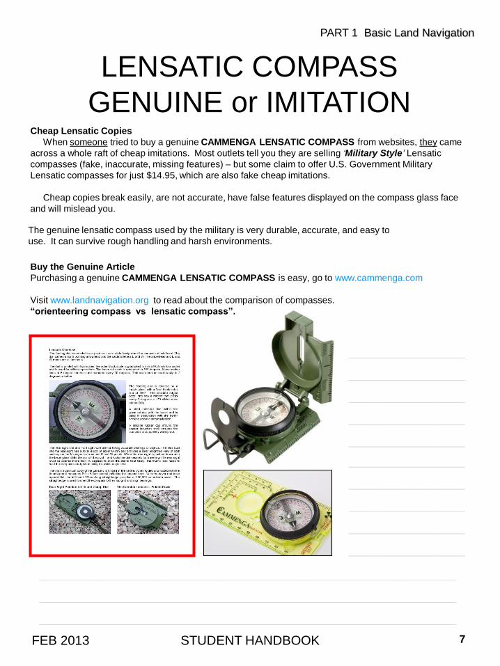
GENUINE or IMITATIONCheap Lensatic Copies
When someone tried to buy a genuine CAMMENGA LENSATIC COMPASS from websites, they came
across a whole raft of cheap imitations. Most outlets tell you they are selling ‘Military Style’ Lensatic
compasses (fake, inaccurate, missing features) – but some claim to offer U.S. Government Military
Lensatic compasses for just $14.95, which are also fake cheap imitations.
Cheap copies break easily, are not accurate, have false features displayed on the compass glass face
and will mislead you.
The genuine lensatic compass used by the military is very durable, accurate, and easy to
use. It can survive rough handling and harsh environments.
Buy the Genuine Article
Purchasing a genuine CAMMENGA LENSATIC COMPASS is easy, go to www.cammenga.com
Visit www.landnavigation.org to read about the comparison of compasses.
“orienteering compass vs lensatic compass”.
STUDENT HANDBOOK 7FEB 2013
PART 1 Basic Land Navigation
___________________
___________________
___________________
___________________
___________________
___________________
___________________
___________________
___________________
___________________
____________________________________________________________________
____________________________________________________________________
____________________________________________________________________
STUDENT HANDBOOK 8FEB 2013
PART 1 Basic Land Navigation
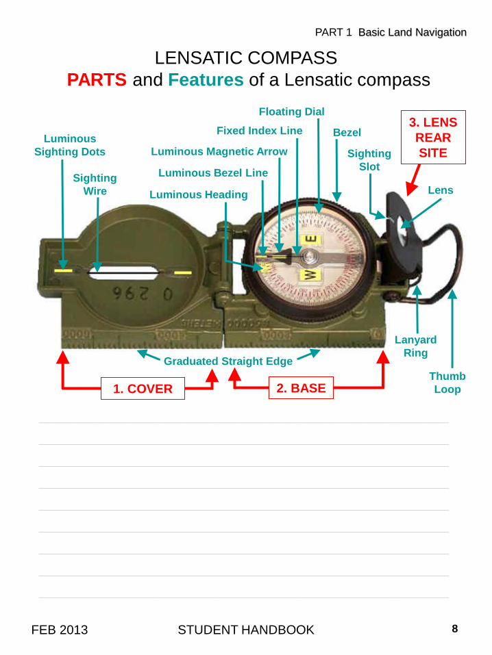
LENSATIC COMPASS
PARTS and Features of a Lensatic compass
____________________________________________________________________
____________________________________________________________________
____________________________________________________________________
____________________________________________________________________
____________________________________________________________________
____________________________________________________________________
____________________________________________________________________
____________________________________________________________________
____________________________________________________________________
Luminous
Sighting Dots
Sighting
Wire Luminous Heading
Luminous Bezel Line
Fixed Index Line
Floating Dial
Bezel
Sighting
Slot
Lens
3. LENS
REAR
SITE
Lanyard
Ring
Thumb
Loop
Graduated Straight Edge
1. COVER 2. BASE
Luminous Magnetic Arrow
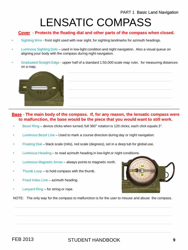
• Bezel Ring – device clicks when turned; full 360° rotation is 120 clicks; each click equals 3°.
• Luminous Bezel Line – Used to mark a course direction during day or night navigation.
• Floating Dial – black scale (mils), red scale (degrees), set in a deep tub for global use.
• Luminous Heading – to read azimuth heading in low-light or night conditions.
• Luminous Magnetic Arrow – always points to magnetic north.
• Thumb Loop – to hold compass with the thumb.
• Fixed Index Line – azimuth heading.
• Lanyard Ring – for string or rope.
NOTE: The only way for the compass to malfunction is for the user to misuse and abuse the compass.
• Sighting Wire - front sight used with rear sight, for sighting landmarks for azimuth headings.
• Luminous Sighting Dots – used in low-light condition and night navigation. Also a visual queue on
aligning your body with the compass during night navigation.
• Graduated Straight Edge - upper half of a standard 1:50,000 scale map ruler, for measuring distances
on a map.
LENSATIC COMPASSCover - Protects the floating dial and other parts of the compass when closed.
STUDENT HANDBOOK 9FEB 2013
PART 1 Basic Land Navigation
Base - The main body of the compass. If, for any reason, the lensatic compass were
to malfunction, the base would be the piece that you would want to still work.
_____________________________________________
_____________________________________________
_____________________________________________
_____________________________________________
_____________________________________________
____________________________________________________________________
____________________________________________________________________
____________________________________________________________________
____________________________________________________________________
____________________________
____________________________
____________________________
____________________________
____________________________
____________________________
____________________________
____________________________
____________________________
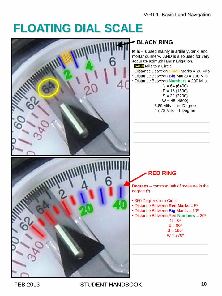
FLOATING DIAL SCALEBLACK RING
Mils - is used mainly in artillery, tank, and
mortar gunnery. AND is also used for very
accurate azimuth land navigation.
• 6400 Mils to a Circle
• Distance Between Small Marks = 20 Mils
• Distance Between Big Marks = 100 Mils
• Distance Between Numbers = 200 Mils
N = 64 (6400)
E = 16 (1600)
S = 32 (3200)
W = 48 (4800)
8.89 Mils = ½ Degree
17.78 Mils = 1 Degree
STUDENT HANDBOOK 10FEB 2013
PART 1 Basic Land Navigation
Degrees – common unit of measure is the
degree (º).
• 360 Degrees to a Circle
• Distance Between Red Marks = 5º
• Distance Between Big Marks = 10º
• Distance Between Red Numbers = 20º
N = 0º
E = 90º
S = 180º
W = 270º
RED RING
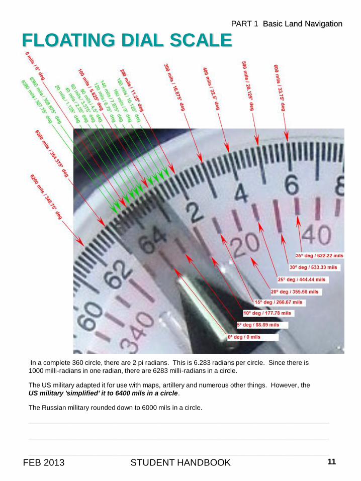
FLOATING DIAL SCALE
STUDENT HANDBOOK 11FEB 2013
PART 1 Basic Land Navigation
In a complete 360 circle, there are 2 pi radians. This is 6.283 radians per circle. Since there is
1000 milli-radians in one radian, there are 6283 milli-radians in a circle.
The US military adapted it for use with maps, artillery and numerous other things. However, the
US military 'simplified' it to 6400 mils in a circle.
The Russian military rounded down to 6000 mils in a circle.
____________________________________________________________________
____________________________________________________________________
____________________________________________________________________
LENSATIC COMPASS
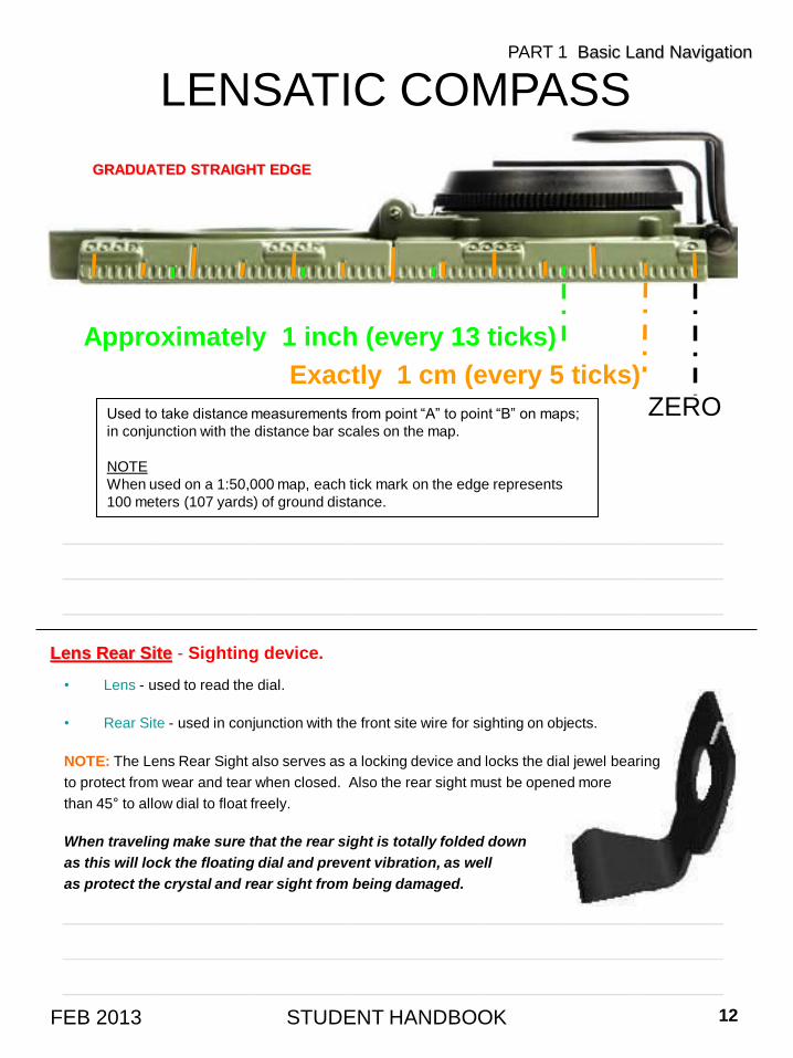
STUDENT HANDBOOK 12FEB 2013
Exactly 1 cm (every 5 ticks)
Approximately 1 inch (every 13 ticks)
ZERO
PART 1 Basic Land Navigation
Used to take distance measurements from point “A” to point “B” on maps;
in conjunction with the distance bar scales on the map.
NOTE
When used on a 1:50,000 map, each tick mark on the edge represents
100 meters (107 yards) of ground distance.
• Lens - used to read the dial.
• Rear Site - used in conjunction with the front site wire for sighting on objects.
NOTE: The Lens Rear Sight also serves as a locking device and locks the dial jewel bearing
to protect from wear and tear when closed. Also the rear sight must be opened more
than 45° to allow dial to float freely.
When traveling make sure that the rear sight is totally folded down
as this will lock the floating dial and prevent vibration, as well
as protect the crystal and rear sight from being damaged.
Lens Rear Site - Sighting device.
GRADUATED STRAIGHT EDGE
____________________________________________________________________
____________________________________________________________________
____________________________________________________________________
____________________________________________________________________
____________________________________________________________________
____________________________________________________________________
Compasses are delicate instruments and should be cared for accordingly. A detailed inspection is required
when first obtaining and using a compass. Important serviceability checks are outlined below:
VISUAL INSPECTION
• Your compass should be opened to see that the cover glass is not broken, clouded, or cracked and
that the compass dial does not stick.
• The front cover should be inspected to see if the cover sighting wire is missing or bent. If it is, use
the center of the opening for sighting purposes, not the wire.
• The eyepiece should be placed flat against the cover glass. The index line on the cover glass should
bisect the sight slot. Then, with the compass closed, it should be noted that the sighting wire also
bisects the sight slot.
This procedure will ensure that the eyepiece is not bent. Gently bend the eyepiece back into
proper alignment, if necessary.
• Check the bezel ring around the face of the compass; it should make a distinct click as it is rotated. If
it does not click, you will have to use an alternate method for night azimuth settings.
MAINTENANCE
• The lensatic compass is built to detailed specifications that were developed in an attempt to increase its
serviceable life. Adherence to very simple maintenance procedures will significantly increase the life of
the lensatic compass. Maintenance procedures are outlined below:
• Rinse in fresh water. This is extremely important, especially after exposure to salt water.
• Brush off dirt and grime. Ensure the "ridges" on the bezel ring are free of dirt. Check movement of the
rear sight to ensure it is free moving.
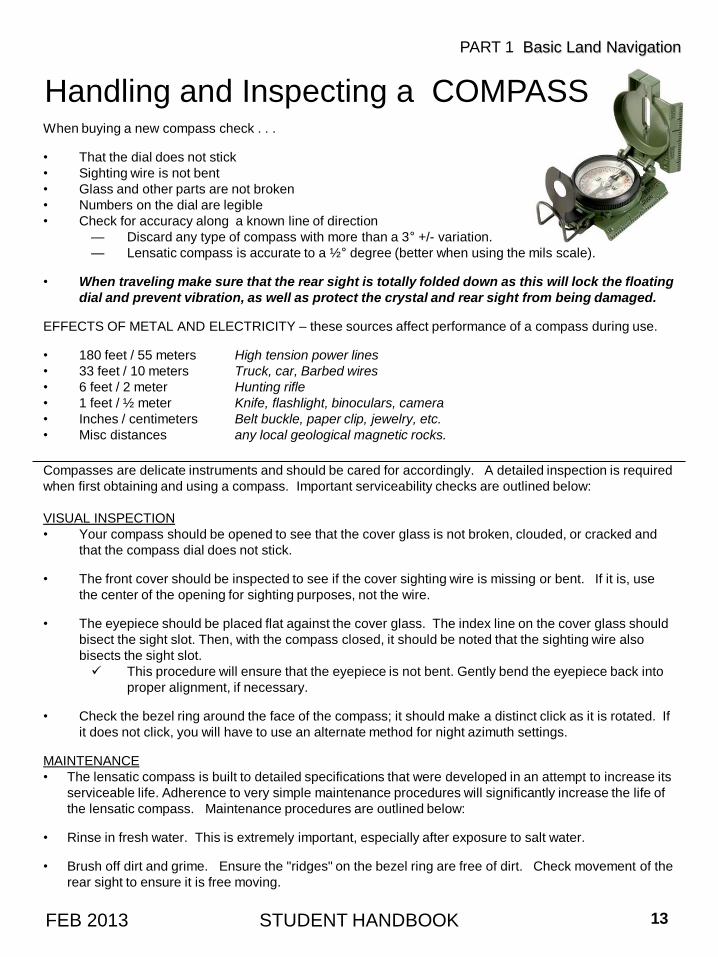
Handling and Inspecting a COMPASSWhen buying a new compass check . . .
• That the dial does not stick
• Sighting wire is not bent
• Glass and other parts are not broken
• Numbers on the dial are legible
• Check for accuracy along a known line of direction
— Discard any type of compass with more than a 3° +/- variation.
— Lensatic compass is accurate to a ½° degree (better when using the mils scale).
• When traveling make sure that the rear sight is totally folded down as this will lock the floating
dial and prevent vibration, as well as protect the crystal and rear sight from being damaged.
EFFECTS OF METAL AND ELECTRICITY – these sources affect performance of a compass during use.
• 180 feet / 55 meters High tension power lines
• 33 feet / 10 meters Truck, car, Barbed wires
• 6 feet / 2 meter Hunting rifle
• 1 feet / ½ meter Knife, flashlight, binoculars, camera
• Inches / centimeters Belt buckle, paper clip, jewelry, etc.
• Misc distances any local geological magnetic rocks.
STUDENT HANDBOOK 13FEB 2013
PART 1 Basic Land Navigation
CALIBRATED / SURVEY
COMPASS ROSE
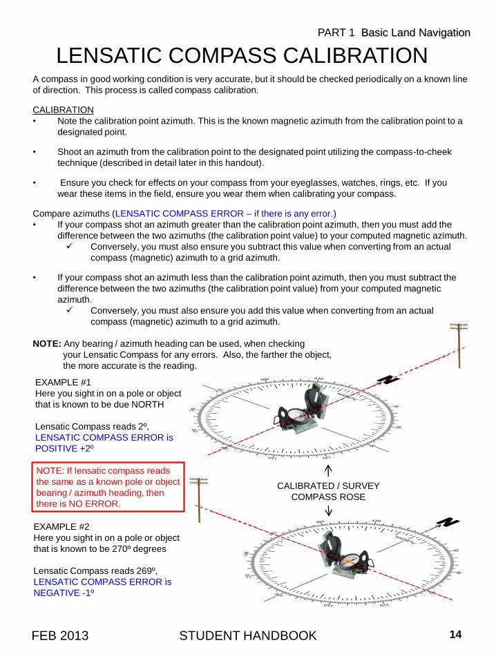
LENSATIC COMPASS CALIBRATIONA compass in good working condition is very accurate, but it should be checked periodically on a known line
of direction. This process is called compass calibration.
CALIBRATION
• Note the calibration point azimuth. This is the known magnetic azimuth from the calibration point to a
designated point.
• Shoot an azimuth from the calibration point to the designated point utilizing the compass-to-cheek
technique (described in detail later in this handout).
• Ensure you check for effects on your compass from your eyeglasses, watches, rings, etc. If you
wear these items in the field, ensure you wear them when calibrating your compass.
Compare azimuths (LENSATIC COMPASS ERROR – if there is any error.)
• If your compass shot an azimuth greater than the calibration point azimuth, then you must add the
difference between the two azimuths (the calibration point value) to your computed magnetic azimuth.
Conversely, you must also ensure you subtract this value when converting from an actual
compass (magnetic) azimuth to a grid azimuth.
• If your compass shot an azimuth less than the calibration point azimuth, then you must subtract the
difference between the two azimuths (the calibration point value) from your computed magnetic
azimuth.
Conversely, you must also ensure you add this value when converting from an actual
compass (magnetic) azimuth to a grid azimuth.
NOTE: Any bearing / azimuth heading can be used, when checking
your Lensatic Compass for any errors. Also, the farther the object,
the more accurate is the reading.
STUDENT HANDBOOK 14FEB 2013
PART 1 Basic Land Navigation
EXAMPLE #1
Here you sight in on a pole or object
that is known to be due NORTH
Lensatic Compass reads 2º,
LENSATIC COMPASS ERROR is
POSITIVE +2º
EXAMPLE #2
Here you sight in on a pole or object
that is known to be 270º degrees
Lensatic Compass reads 269º,
LENSATIC COMPASS ERROR is
NEGATIVE -1º
NOTE: If lensatic compass reads
the same as a known pole or object
bearing / azimuth heading, then
there is NO ERROR.
LENSATIC COMPASS CALIBRATION
STUDENT HANDBOOK 15FEB 2013
PART 1 Basic Land Navigation
Calibrated/ Surveyed
Compass Rose
65º
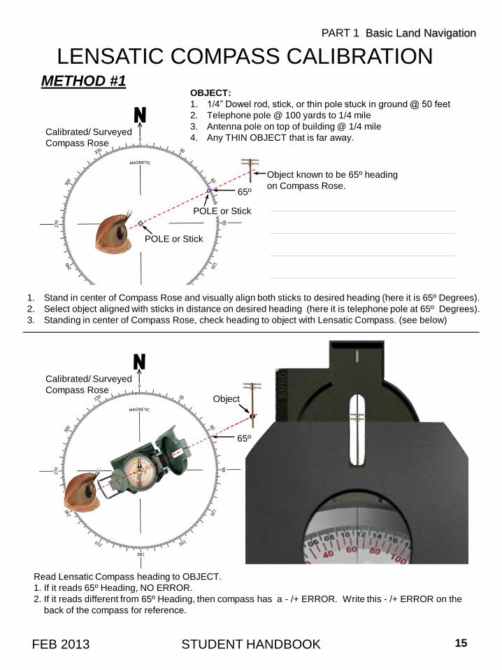
Read Lensatic Compass heading to OBJECT.
1. If it reads 65º Heading, NO ERROR.
2. If it reads different from 65º Heading, then compass has a - /+ ERROR. Write this - /+ ERROR on the
back of the compass for reference.
METHOD #1
Object known to be 65º heading
on Compass Rose.65º
OBJECT:
1. 1/4” Dowel rod, stick, or thin pole stuck in ground @ 50 feet
2. Telephone pole @ 100 yards to 1/4 mile
3. Antenna pole on top of building @ 1/4 mile
4. Any THIN OBJECT that is far away.
POLE or Stick
POLE or Stick
1. Stand in center of Compass Rose and visually align both sticks to desired heading (here it is 65º Degrees).
2. Select object aligned with sticks in distance on desired heading (here it is telephone pole at 65º Degrees).
3. Standing in center of Compass Rose, check heading to object with Lensatic Compass. (see below)
Calibrated/ Surveyed
Compass Rose
Object
______________________________
______________________________
______________________________
______________________________
LENSATIC COMPASS CALIBRATION
STUDENT HANDBOOK 16FEB 2013
PART 1 Basic Land Navigation
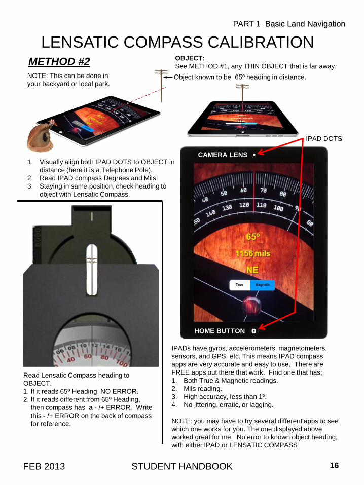
Read Lensatic Compass heading to
OBJECT.
1. If it reads 65º Heading, NO ERROR.
2. If it reads different from 65º Heading,
then compass has a - /+ ERROR. Write
this - /+ ERROR on the back of compass
for reference.
METHOD #2
1. Visually align both IPAD DOTS to OBJECT in
distance (here it is a Telephone Pole).
2. Read IPAD compass Degrees and Mils.
3. Staying in same position, check heading to
object with Lensatic Compass.
OBJECT:
See METHOD #1, any THIN OBJECT that is far away.
Object known to be 65º heading in distance.
IPAD DOTS
IPADs have gyros, accelerometers, magnetometers,
sensors, and GPS, etc. This means IPAD compass
apps are very accurate and easy to use. There are
FREE apps out there that work. Find one that has;
1. Both True & Magnetic readings.
2. Mils reading.
3. High accuracy, less than 1º.
4. No jittering, erratic, or lagging.
NOTE: you may have to try several different apps to see
which one works for you. The one displayed above
worked great for me. No error to known object heading,
with either IPAD or LENSATIC COMPASS
CAMERA LENS
HOME BUTTON
NOTE: This can be done in
your backyard or local park.
______________________
______________________
______________________
______________________
______________________
LENSATIC COMPASS CALIBRATION
STUDENT HANDBOOK 17FEB 2013
PART 1 Basic Land Navigation
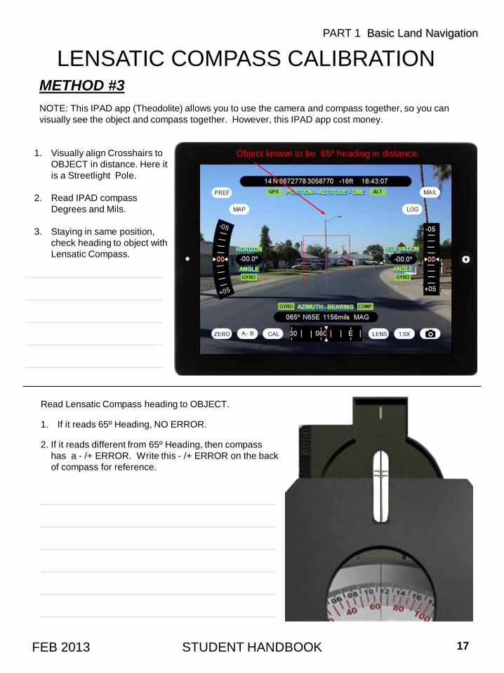
Read Lensatic Compass heading to OBJECT.
1. If it reads 65º Heading, NO ERROR.
2. If it reads different from 65º Heading, then compass
has a - /+ ERROR. Write this - /+ ERROR on the back
of compass for reference.
METHOD #3
1. Visually align Crosshairs to
OBJECT in distance. Here it
is a Streetlight Pole.
2. Read IPAD compass
Degrees and Mils.
3. Staying in same position,
check heading to object with
Lensatic Compass.
NOTE: This IPAD app (Theodolite) allows you to use the camera and compass together, so you can
visually see the object and compass together. However, this IPAD app cost money.
Object known to be 65º heading in distance.
______________________________________
______________________________________
______________________________________
______________________________________
______________________________________
______________________________________
_______________
_______________
_______________
_______________
_______________
_______________________________________
_______________________________________
_______________________________________
_______________________________________
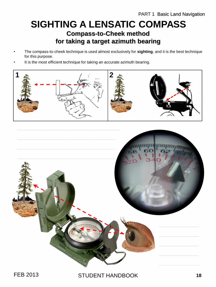
Compass-to-Cheek method
for taking a target azimuth bearing
• The compass-to-cheek technique is used almost exclusively for sighting, and it is the best technique
for this purpose.
• It is the most efficient technique for taking an accurate azimuth bearing.
SIGHTING A LENSATIC COMPASS
STUDENT HANDBOOK 18FEB 2013
PART 1 Basic Land Navigation
1 2
STUDENT HANDBOOK 19FEB 2013
PART 1 Basic Land Navigation
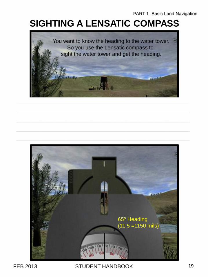
SIGHTING A LENSATIC COMPASS
65º Heading
(11.5 =1150 mils)
You want to know the heading to the water tower.
So you use the Lensatic compass to
sight the water tower and get the heading.
____________________________________________________________________
____________________________________________________________________
____________________________________________________________________
____________________________________________________________________
____________________________________________________________________
__________________________________________________________
__________________________________________________________
__________________________________________________________
___________________________________________________________
___________________________________________________________
___________________________________________________________
___________________________________________________________
___________________________________________________________
___________________________________________________________
___________________________________________________________
___________________________________________________________
___________________________________________________________
___________________________________________________
___________________________________________________
___________________________________________________
___________________________________________________
___________________________________________________
___________________________________________________
___________________________________________________
___________________________________________________
STUDENT HANDBOOK 20FEB 2013
PART 1 Basic Land Navigation
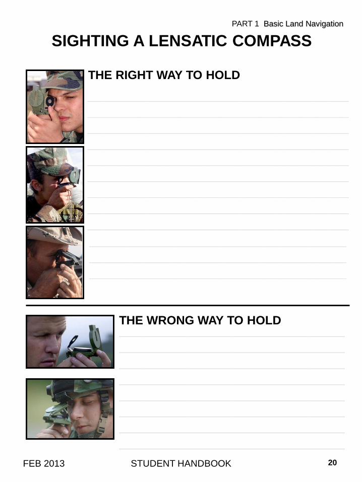
SIGHTING A LENSATIC COMPASS
THE RIGHT WAY TO HOLD
THE WRONG WAY TO HOLD

Center-Hold method for taking a target azimuth bearing
The center-hold technique is less precise, but is faster to use and can be used under all conditions of visibility.
1. Open the cover until it forms a straight edge with the base.
2. Pull the rear sight to the rear most position, allowing the dial to float freely.
3. Next, place your thumb through the thumb loop, form a steady base with your third and fourth fingers, and extend your index finger along the side of the compass.
4. Place the thumb of the other hand between the rear sight and the bezel ring; extend the index finger along the remaining side of the compass, and the remaining fingers around the fingers of the other hand.
5. Pull your elbows firmly into your sides; this will place the compass between your chin and your belt.
6. To measure azimuth, turn entire body toward the object, pointing the compass cover directly at the object.
7. Once you are pointing at the object, look down and read the azimuth from the fixed black index line.
LENSATIC COMPASS
STUDENT HANDBOOK 21FEB 2013
PART 1 Basic Land Navigation
____________________________________________________________________
____________________________________________________________________
____________________________________________________________________
____________________________________________________________________
____________________________________________________________________
____________________________________________________________________
____________________________________________________________________
____________________________________________________________________
____________________________________________________________________
____________________________________________________________________
____________________________________________________________________
____________________________________________________________________
____________________________________________________________________
____________________________________________________________________
____________________________________________________________________
____________________________________________________________________
____________________________________________________________________
____________________________________________________________________
LENSATIC COMPASS
PART 1 Basic Land Navigation
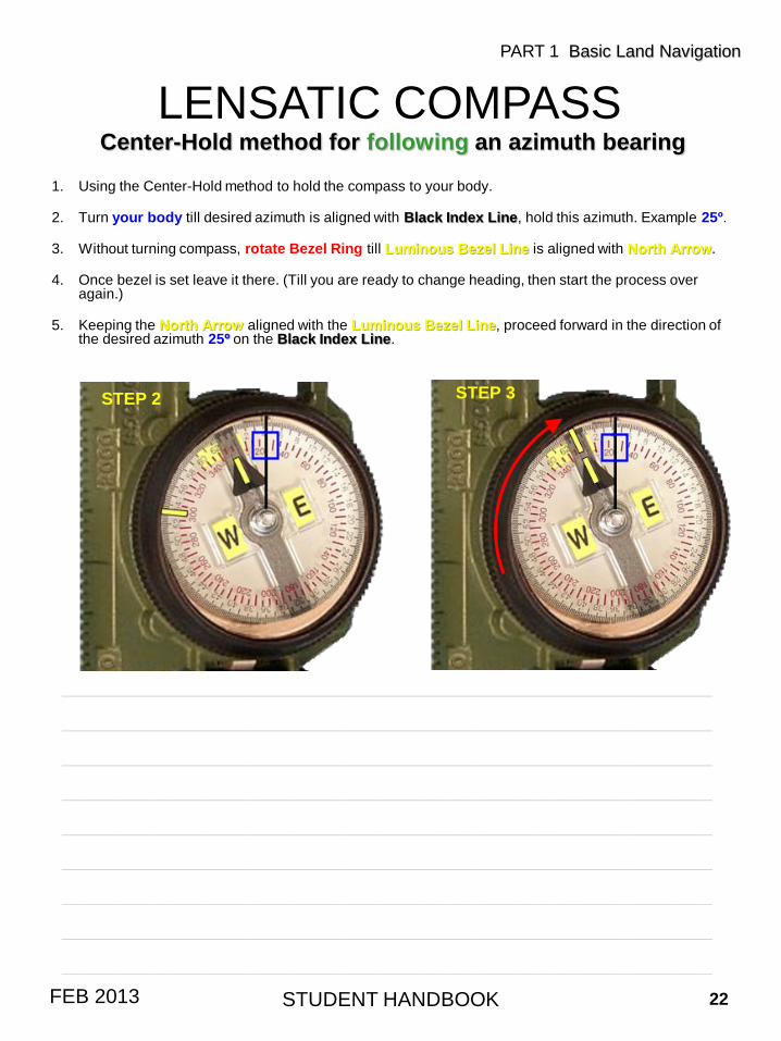
Center-Hold method for following an azimuth bearing
1. Using the Center-Hold method to hold the compass to your body.
2. Turn your body till desired azimuth is aligned with Black Index Line, hold this azimuth. Example 25º.
3. Without turning compass, rotate Bezel Ring till Luminous Bezel Line is aligned with North Arrow.
4. Once bezel is set leave it there. (Till you are ready to change heading, then start the process over again.)
5. Keeping the North Arrow aligned with the Luminous Bezel Line, proceed forward in the direction of the desired azimuth 25º on the Black Index Line.
STUDENT HANDBOOK 22FEB 2013
STEP 2 STEP 3
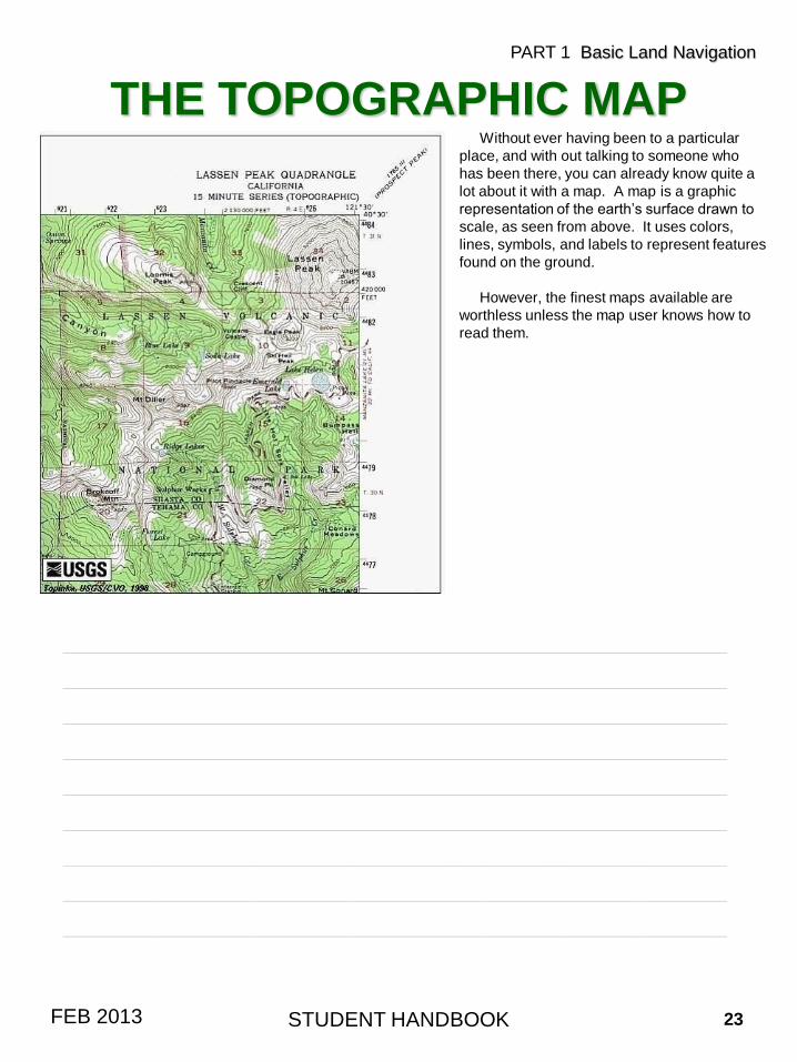
THE TOPOGRAPHIC MAPWithout ever having been to a particular
place, and with out talking to someone who
has been there, you can already know quite a
lot about it with a map. A map is a graphic
representation of the earth’s surface drawn to
scale, as seen from above. It uses colors,
lines, symbols, and labels to represent features
found on the ground.
However, the finest maps available are
worthless unless the map user knows how to
read them.
STUDENT HANDBOOK 23FEB 2013
PART 1 Basic Land Navigation
____________________________________________________________________
____________________________________________________________________
____________________________________________________________________
____________________________________________________________________
____________________________________________________________________
____________________________________________________________________
____________________________________________________________________
____________________________________________________________________
____________________________________________________________________
TOPOGRAPHIC MAPDESCRIPTION
• Reading a map is a language composed of lines, colors, and symbols.
• Five basic colors are used for Topographic Maps.
– Brown (Contour Lines)
– Black (Man Made Features, Roads, Trails)
– Blue (Water Features)
– Green (Vegetation)
– Red (Highway and Land Grids)
– Two minor colors
• Pink (Built up area, civilization)
• Purple (Updated Map Information)
• Symbols are used to represent the natural and man-made features of the earth.
• Lines show relief and elevation; it indicates variations in terrain features and heights of natural features.
• Every map has Margin Information about the map.
• Maps come in three scale sizes; SMALL, MEDIUM, and LARGE. Which affects the amount of area covered and detail that will be shown.
• A map is read for four basic kinds of information.
– Direction
– Distance
– Position
– Identification
• Maps must be taken care of and properly folded for field use.
STUDENT HANDBOOK 24FEB 2013
PART 1 Basic Land Navigation
____________________________________________________________________
____________________________________________________________________
____________________________________________________________________
____________________________________________________________________
____________________________________________________________________
____________________________________________________________________
____________________________________________________________________
____________________________________________________________________
____________________________________________________________________
____________________________________________________________________
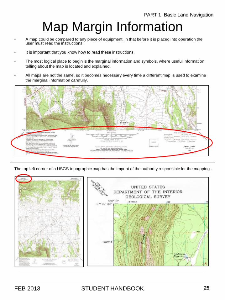
• A map could be compared to any piece of equipment, in that before it is placed into operation the user must read the instructions.
• It is important that you know how to read these instructions.
• The most logical place to begin is the marginal information and symbols, where useful information
telling about the map is located and explained.
• All maps are not the same, so it becomes necessary every time a different map is used to examine
the marginal information carefully.
Map Margin Information
STUDENT HANDBOOK 25FEB 2013
PART 1 Basic Land Navigation
The top left corner of a USGS topographic map has the imprint of the authority responsible for the mapping .
____________________________________________________________________
____________________________________________________________________
STUDENT HANDBOOK 26FEB 2013
Map Margin InformationPART 1 Basic Land Navigation
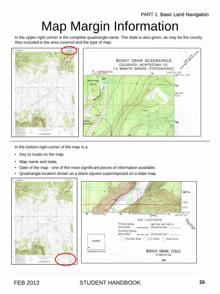
In the upper right corner is the complete quadrangle name. The state is also given, as may be the county.
Also included is the area covered and the type of map.
In the bottom right corner of the map is a
• Key to roads on the map.
• Map name and state.
• Date of the map - one of the most significant pieces of information available.
• Quadrangle location shown as a black square superimposed on a state map.
____________________________________________________________________
STUDENT HANDBOOK 27FEB 2013
Map Margin InformationPART 1 Basic Land Navigation
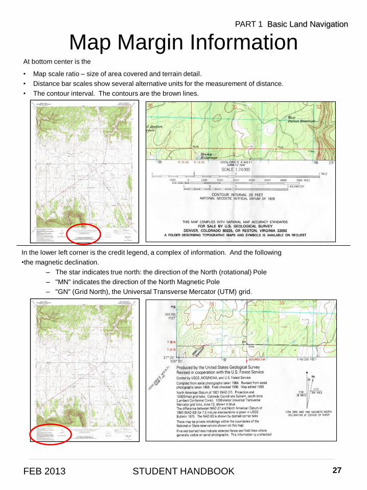
At bottom center is the
• Map scale ratio – size of area covered and terrain detail.
• Distance bar scales show several alternative units for the measurement of distance.
• The contour interval. The contours are the brown lines.
In the lower left corner is the credit legend, a complex of information. And the following
•the magnetic declination.
– The star indicates true north: the direction of the North (rotational) Pole
– "MN" indicates the direction of the North Magnetic Pole
– "GN" (Grid North), the Universal Transverse Mercator (UTM) grid.
____________________________________________________________________
STUDENT HANDBOOK 28FEB 2013
Map Margin InformationPART 1 Basic Land Navigation
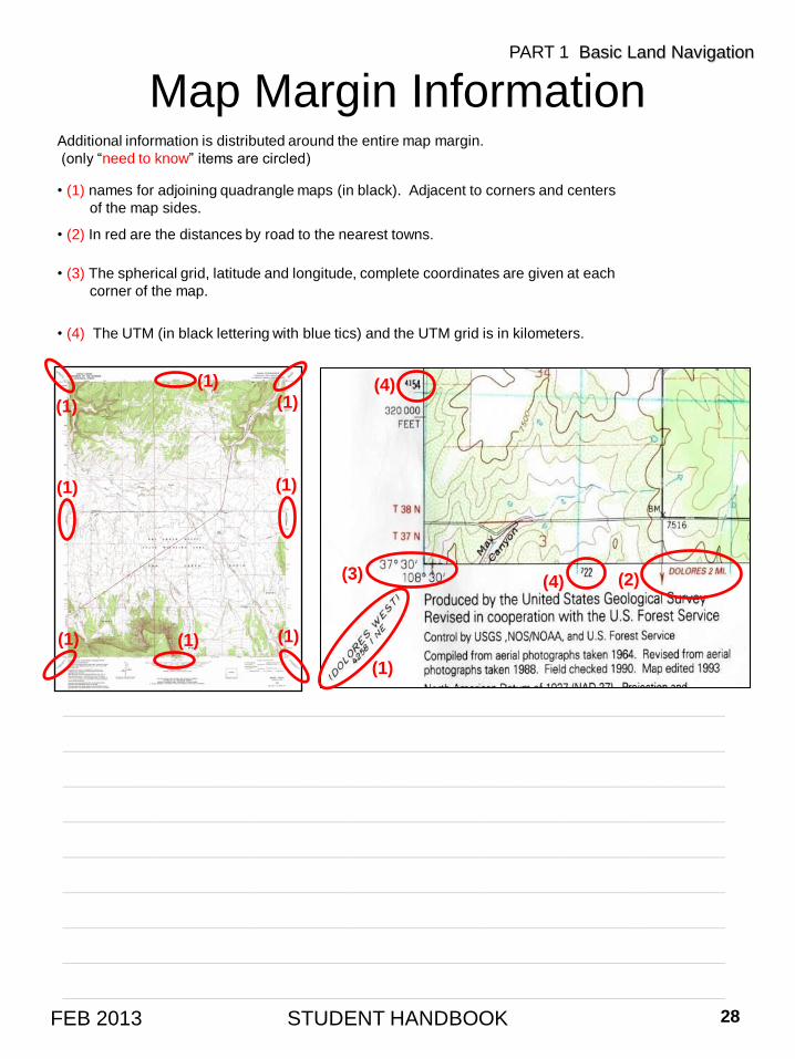
Additional information is distributed around the entire map margin.
(only “need to know” items are circled)
• (1) names for adjoining quadrangle maps (in black). Adjacent to corners and centers
of the map sides.
• (2) In red are the distances by road to the nearest towns.
• (3) The spherical grid, latitude and longitude, complete coordinates are given at each
corner of the map.
• (4) The UTM (in black lettering with blue tics) and the UTM grid is in kilometers.
(2)
(1)
(4)(3)
(4)
(1)(1)(1)
(1) (1)
(1) (1)
(1)
____________________________________________________________________
____________________________________________________________________
____________________________________________________________________
____________________________________________________________________
____________________________________________________________________
____________________________________________________________________
____________________________________________________________________
____________________________________________________________________
____________________________________________________________________
Map Scale• Map scale is the relationship between distance on a map and the corresponding distance on the
ground. Scale is expressed as a ratio, such as 1:24,000, and shown graphically by bar scales
marked in feet and miles, or in meters and kilometers. Maps with a small scale for example, 7.5-
minute maps, are often called large-scale maps because they show more detail (by covering less
area) than a large bar-scale (30- x 60-minute) map.
• You must know the scale to determine ground distances between objects or locations on the map,
the size of the area covered, and how the scale may affect the amount of detail being shown.
• The terms “small scale,” “medium scale,” and “large scale” may be confusing when read in
conjunction with the number.
• However, if the number is viewed as a fraction, it quickly becomes apparent that 1:600,000 of
something is smaller than 1:75,000 of the same thing. Therefore, the larger the number after 1:, the
smaller the scale of the map.
• (1) Small. Maps with scales of 1:1,000,000 and smaller are used for general planning and for
strategic studies. The standard small-scale map is 1:1,000,000 (1 inch = 16 miles). This map
covers a very large land area at the expense of less detail.
• (2) Medium. Maps with scales larger than 1:1,000,000 but smaller than 1:75,000 are used for
operational planning. They contain a moderate amount of detail, but terrain analysis is best done
with the large-scale maps. The standard medium-scale map is 1:250,000 (1 inch = 4 miles).
Medium-scale maps of 1:100,000 are also frequently encountered.
• (3) Large. Maps with scales of 1:75,000 and larger are used for tactical, administrative, and
logistical planning. These are the maps that you as a Soldier or junior leader are most likely to
encounter. The standard large-scale map is 1:50,000; however, many areas have been
mapped at a scale of 1:25,000 (1 inch = 2,000 feet). Lots of detail is shown on this type of map.
STUDENT HANDBOOK 29FEB 2013
PART 1 Basic Land Navigation
____________________________________________________________________
____________________________________________________________________
____________________________________________________________________
____________________________________________________________________
____________________________________________________________________
____________________________________________________________________
____________________________________________________________________
____________________________________________________________________
____________________________________________________________________
STUDENT HANDBOOK 30FEB 2013
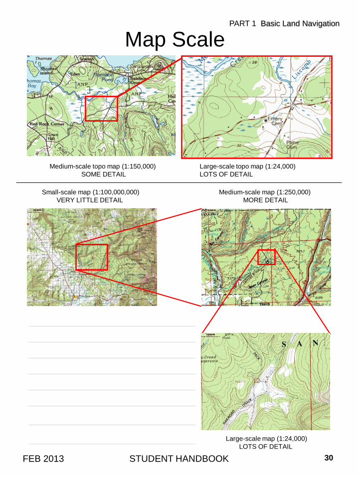
Map ScalePART 1 Basic Land Navigation
Large-scale topo map (1:24,000)
LOTS OF DETAIL
Medium-scale topo map (1:150,000)
SOME DETAIL
Small-scale map (1:100,000,000)
VERY LITTLE DETAIL
Medium-scale map (1:250,000)
MORE DETAIL
Large-scale map (1:24,000)
LOTS OF DETAIL
______________________________________
______________________________________
______________________________________
______________________________________
______________________________________
______________________________________
______________________________________
______________________________________
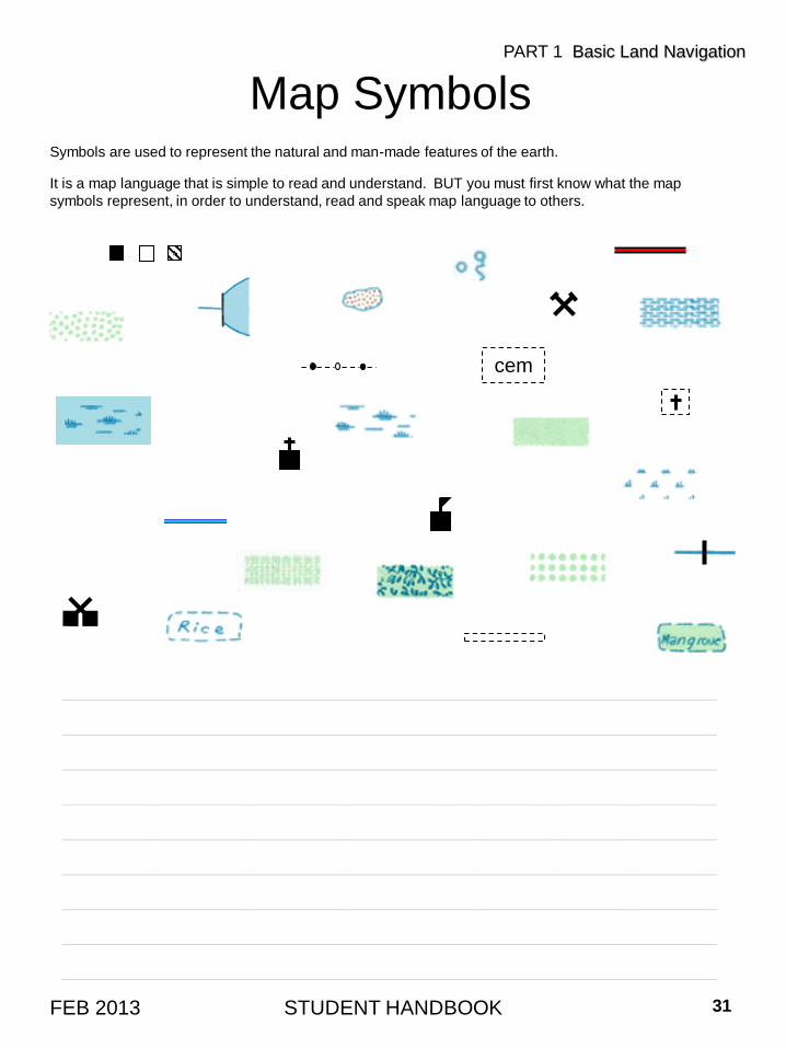
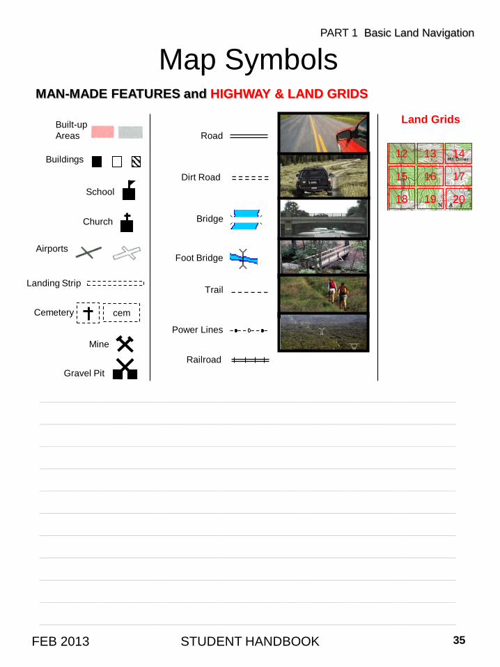
Map SymbolsSymbols are used to represent the natural and man-made features of the earth.
It is a map language that is simple to read and understand. BUT you must first know what the map
symbols represent, in order to understand, read and speak map language to others.
STUDENT HANDBOOK 31FEB 2013
PART 1 Basic Land Navigation
cem
____________________________________________________________________
____________________________________________________________________
____________________________________________________________________
____________________________________________________________________
____________________________________________________________________
____________________________________________________________________
____________________________________________________________________
____________________________________________________________________
____________________________________________________________________
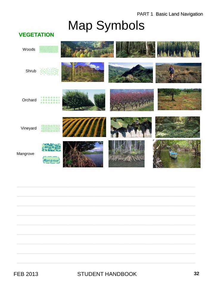
VEGETATION
STUDENT HANDBOOK 32FEB 2013
Map SymbolsPART 1 Basic Land Navigation
Woods
Shrub
Orchard
Vineyard
Mangrove
____________________________________________________________________
____________________________________________________________________
____________________________________________________________________
____________________________________________________________________
____________________________________________________________________
____________________________________________________________________
____________________________________________________________________
____________________________________________________________________
____________________________________________________________________
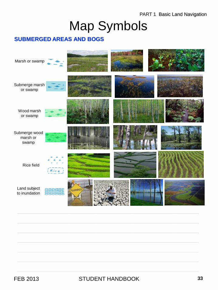
SUBMERGED AREAS AND BOGS
STUDENT HANDBOOK 33FEB 2013
Map SymbolsPART 1 Basic Land Navigation
Submerge wood
marsh or
swamp
Marsh or swamp
Submerge marsh
or swamp
Wood marsh
or swamp
Rice field
Land subject
to inundation
____________________________________________________________________
____________________________________________________________________
____________________________________________________________________
____________________________________________________________________
____________________________________________________________________
____________________________________________________________________
____________________________________________________________________
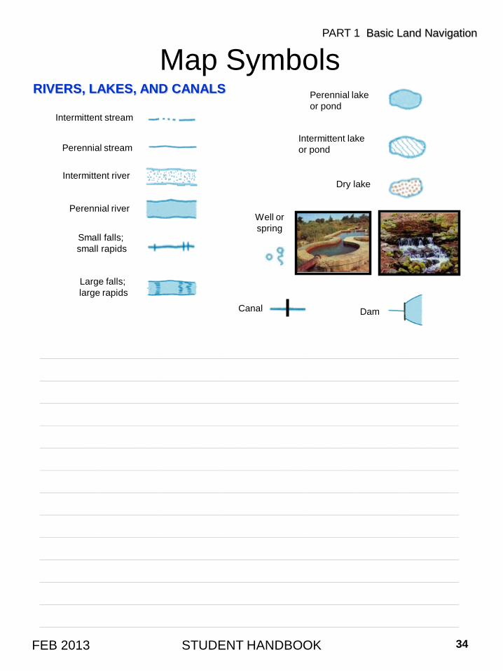
RIVERS, LAKES, AND CANALS
STUDENT HANDBOOK 34FEB 2013
Map SymbolsPART 1 Basic Land Navigation
Intermittent stream
Perennial stream
Intermittent river
Perennial river
Small falls;
small rapids
Large falls;
large rapids
Perennial lake
or pond
Intermittent lake
or pond
Dry lake
Well or
spring
DamCanal
____________________________________________________________________
____________________________________________________________________
____________________________________________________________________
____________________________________________________________________
____________________________________________________________________
____________________________________________________________________
____________________________________________________________________
____________________________________________________________________
____________________________________________________________________
____________________________________________________________________
____________________________________________________________________
____________________________________________________________________
____________________________________________________________________
MAN-MADE FEATURES and HIGHWAY & LAND GRIDS
STUDENT HANDBOOK 35FEB 2013
Map SymbolsPART 1 Basic Land Navigation
Road
Dirt Road
Trail
Power Lines
Bridge
Foot Bridge
Railroad
Land Grids
12 13 14
15 16 17
18 19 20
Built-up
Areas
Buildings
Airports
Landing Strip
School
Church
cemCemetery
Mine
Gravel Pit
____________________________________________________________________
____________________________________________________________________
____________________________________________________________________
____________________________________________________________________
____________________________________________________________________
____________________________________________________________________
____________________________________________________________________
____________________________________________________________________
____________________________________________________________________
____________________________________________________________________
____________________________________________________________________
CONTOUR LINES
STUDENT HANDBOOK 36FEB 2013
PART 1 Basic Land Navigation
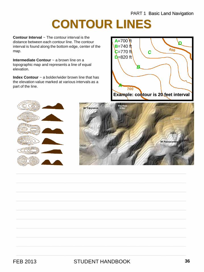
Example: contour is 20 feet interval
A=700 ft
B=740 ft
C=770 ft
D=820 ft
Contour Interval ~ The contour interval is the
distance between each contour line. The contour
interval is found along the bottom edge, center of the
map.
Intermediate Contour ~ a brown line on a
topographic map and represents a line of equal
elevation.
Index Contour ~ a bolder/wider brown line that has
the elevation value marked at various intervals as a
part of the line.
____________________________________________________________________
____________________________________________________________________
____________________________________________________________________
____________________________________________________________________
____________________________________________________________________
____________________________________________________________________
____________________________________________________________________
____________________________________________________________________
____________________________________________________________________
____________________________________________________________________
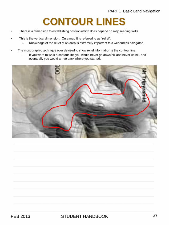
• There is a dimension to establishing position which does depend on map reading skills.
• This is the vertical dimension. On a map it is referred to as “relief”.
– Knowledge of the relief of an area is extremely important to a wilderness navigator.
• The most graphic technique ever devised to show relief information is the contour line.
– If you were to walk a contour line you would never go down hill and never up hill, and
eventually you would arrive back where you started.
STUDENT HANDBOOK 37FEB 2013
CONTOUR LINES
PART 1 Basic Land Navigation
____________________________________________________________________
____________________________________________________________________
____________________________________________________________________
____________________________________________________________________
____________________________________________________________________
____________________________________________________________________
____________________________________________________________________
____________________________________________________________________
____________________________________________________________________
____________________________________________________________________
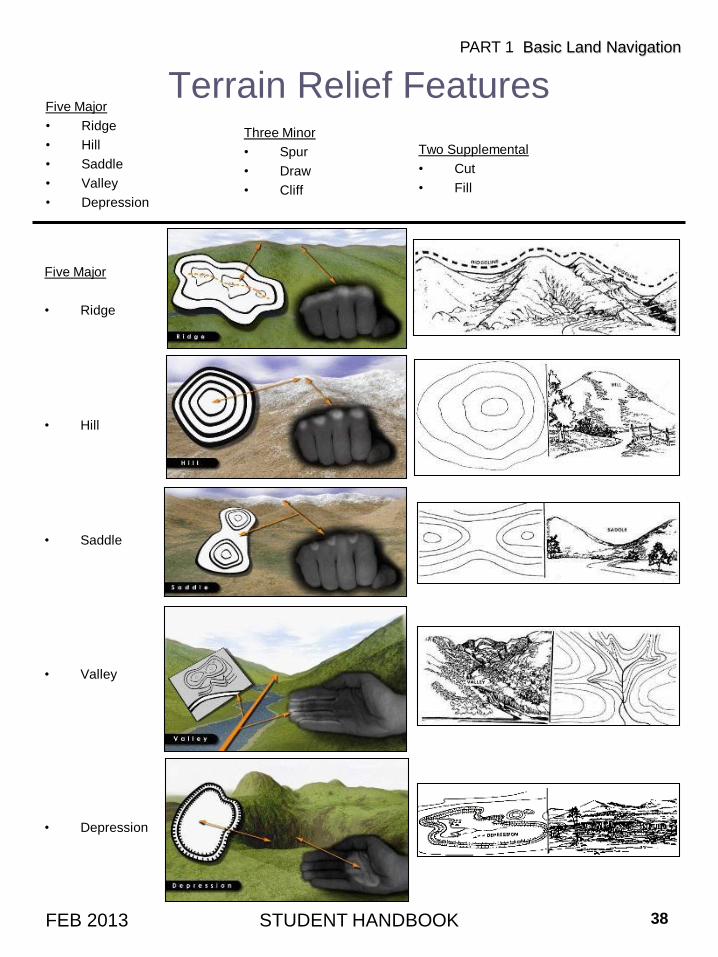
Five Major
• Ridge
• Hill
• Saddle
• Valley
• Depression
Terrain Relief FeaturesFive Major
• Ridge
• Hill
• Saddle
• Valley
• Depression
STUDENT HANDBOOK 38FEB 2013
PART 1 Basic Land Navigation
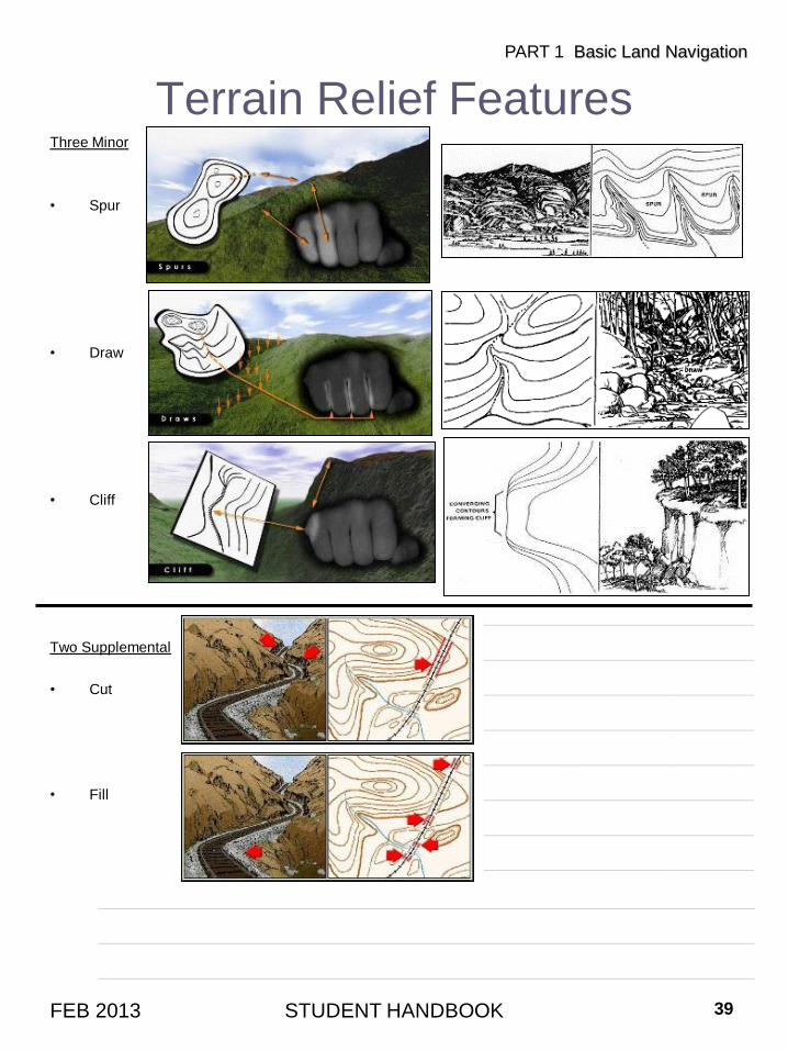
Three Minor
• Spur
• Draw
• Cliff
Two Supplemental
• Cut
• Fill
Terrain Relief FeaturesThree Minor
• Spur
• Draw
• Cliff
Two Supplemental
• Cut
• Fill
STUDENT HANDBOOK 39FEB 2013
PART 1 Basic Land Navigation
____________________________
____________________________
____________________________
____________________________
____________________________
____________________________
____________________________
____________________________
____________________________________________________________________
____________________________________________________________________
____________________________________________________________________
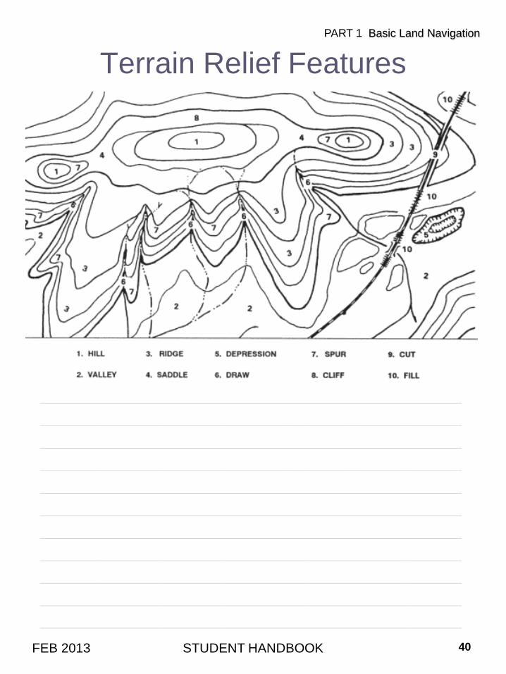
Terrain Relief Features
STUDENT HANDBOOK 40FEB 2013
PART 1 Basic Land Navigation
____________________________________________________________________
____________________________________________________________________
____________________________________________________________________
____________________________________________________________________
____________________________________________________________________
____________________________________________________________________
____________________________________________________________________
____________________________________________________________________
____________________________________________________________________
____________________________________________________________________
____________________________________________________________________
Map Information – DirectionEXPRESSING DIRECTION
• You need a way of expressing direction that is accurate, is adaptable to any part of the world, and
has a common unit of measure. Directions are expressed as units of angular measure and direction
implies a reference point.
• The common reference point for maps is True North, and map direction is figured in degrees from
that point.
• Azimuths - The direction from one point to another point (either on the map or on the ground) is
called an azimuth.
– Azimuths are given in degrees in a clockwise direction. Since there are 360° in a circle, an
azimuth can be any number up to 360°. East is 90°, South is 180°, West is 270°, and North
is 360°.
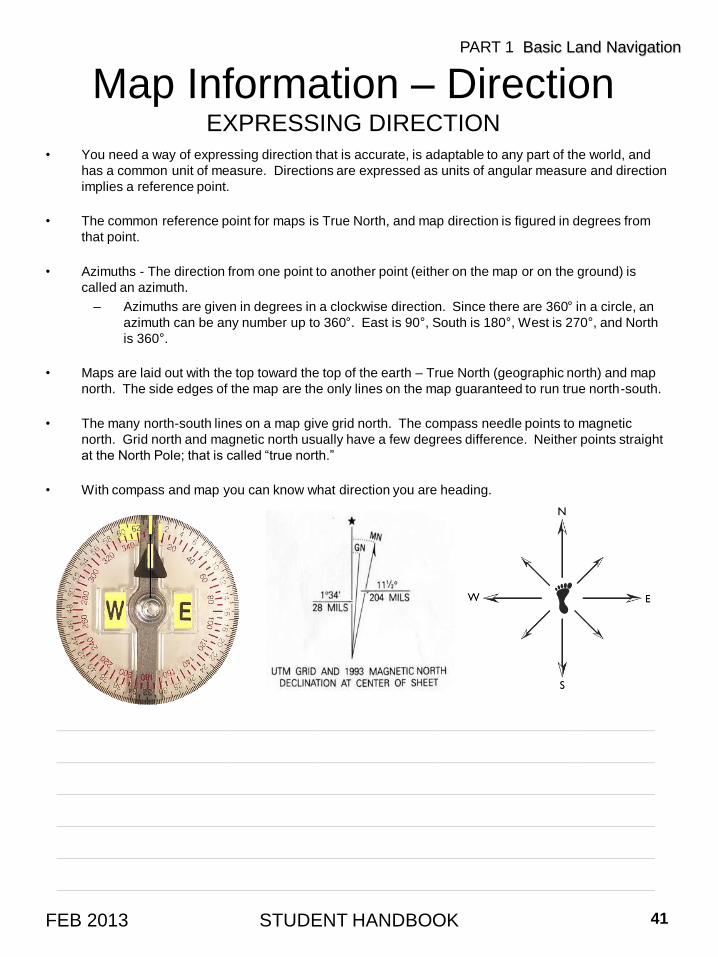
• Maps are laid out with the top toward the top of the earth – True North (geographic north) and map
north. The side edges of the map are the only lines on the map guaranteed to run true north-south.
• The many north-south lines on a map give grid north. The compass needle points to magnetic
north. Grid north and magnetic north usually have a few degrees difference. Neither points straight
at the North Pole; that is called “true north.”
• With compass and map you can know what direction you are heading.
STUDENT HANDBOOK 41FEB 2013
PART 1 Basic Land Navigation
____________________________________________________________________
____________________________________________________________________
____________________________________________________________________
____________________________________________________________________
____________________________________________________________________
____________________________________________________________________
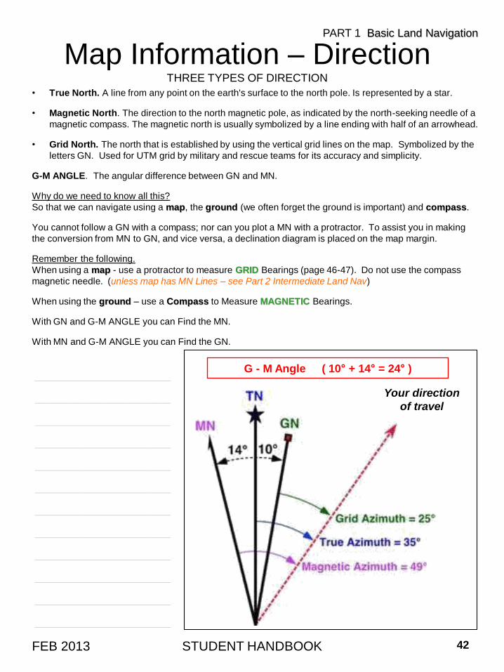
• True North. A line from any point on the earth's surface to the north pole. Is represented by a star.
• Magnetic North. The direction to the north magnetic pole, as indicated by the north-seeking needle of a
magnetic compass. The magnetic north is usually symbolized by a line ending with half of an arrowhead.
• Grid North. The north that is established by using the vertical grid lines on the map. Symbolized by the
letters GN. Used for UTM grid by military and rescue teams for its accuracy and simplicity.
G-M ANGLE. The angular difference between GN and MN.
Why do we need to know all this?
So that we can navigate using a map, the ground (we often forget the ground is important) and compass.
You cannot follow a GN with a compass; nor can you plot a MN with a protractor. To assist you in making
the conversion from MN to GN, and vice versa, a declination diagram is placed on the map margin.
Remember the following.
When using a map - use a protractor to measure GRID Bearings (page 46-47). Do not use the compass
magnetic needle. (unless map has MN Lines – see Part 2 Intermediate Land Nav)
When using the ground – use a Compass to Measure MAGNETIC Bearings.
With GN and G-M ANGLE you can Find the MN.
With MN and G-M ANGLE you can Find the GN.
Map Information – DirectionTHREE TYPES OF DIRECTION
STUDENT HANDBOOK 42FEB 2013
PART 1 Basic Land Navigation
Your direction
of travel
G - M Angle ( 10° + 14° = 24° )______________________
______________________
______________________
______________________
______________________
______________________
______________________
______________________
______________________
______________________
______________________
______________________
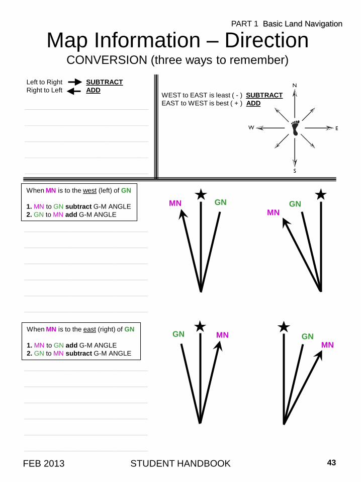
Map Information – DirectionCONVERSION (three ways to remember)
STUDENT HANDBOOK 43FEB 2013
PART 1 Basic Land Navigation
WEST to EAST is least ( - ) SUBTRACT
EAST to WEST is best ( + ) ADD
Left to Right SUBTRACT
Right to Left ADD
GN MN GNMN
When MN is to the west (left) of GN
1. MN to GN subtract G-M ANGLE
2. GN to MN add G-M ANGLE
When MN is to the east (right) of GN
1. MN to GN add G-M ANGLE
2. GN to MN subtract G-M ANGLE
GNMN GNMN
____________________________
____________________________
____________________________
____________________________
____________________________
____________________________
____________________________
____________________________
____________________________
____________________________
____________________________
____________________________
____________________________
____________________________
____________________________
____________________________
____________________________
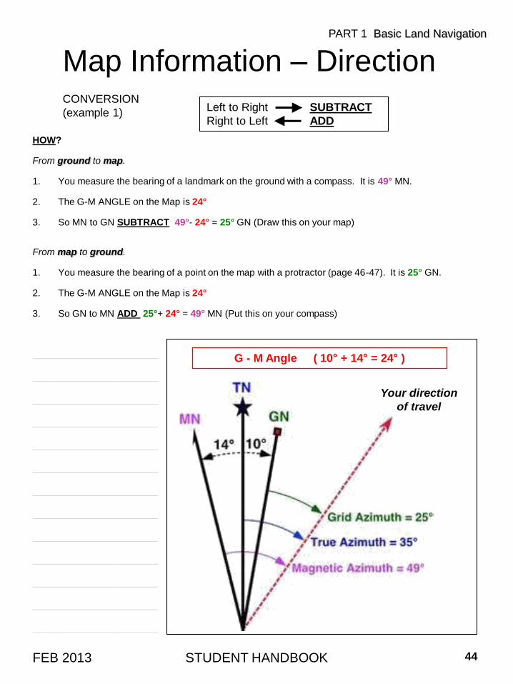
HOW?
From ground to map.
1. You measure the bearing of a landmark on the ground with a compass. It is 49° MN.
2. The G-M ANGLE on the Map is 24°
3. So MN to GN SUBTRACT 49°- 24° = 25° GN (Draw this on your map)
From map to ground.
1. You measure the bearing of a point on the map with a protractor (page 46-47). It is 25° GN.
2. The G-M ANGLE on the Map is 24°
3. So GN to MN ADD 25°+ 24° = 49° MN (Put this on your compass)
Map Information – DirectionCONVERSION
(example 1)Left to Right SUBTRACT
Right to Left ADD
STUDENT HANDBOOK 44FEB 2013
PART 1 Basic Land Navigation
Your direction
of travel
G - M Angle ( 10° + 14° = 24° )____________________
____________________
____________________
____________________
____________________
____________________
____________________
____________________
____________________
____________________
____________________
____________________
____________________
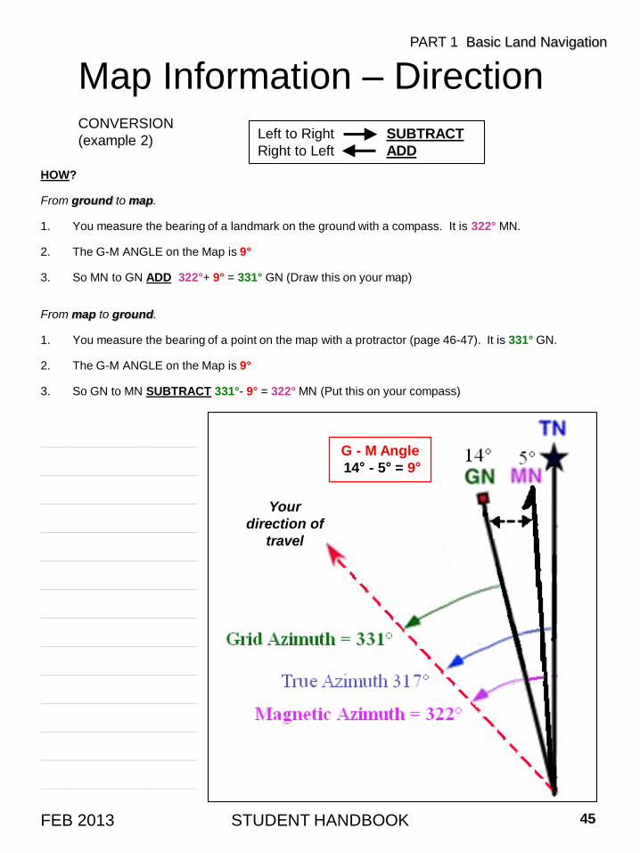
HOW?
From ground to map.
1. You measure the bearing of a landmark on the ground with a compass. It is 322° MN.
2. The G-M ANGLE on the Map is 9°
3. So MN to GN ADD 322°+ 9° = 331° GN (Draw this on your map)
From map to ground.
1. You measure the bearing of a point on the map with a protractor (page 46-47). It is 331° GN.
2. The G-M ANGLE on the Map is 9°
3. So GN to MN SUBTRACT 331°- 9° = 322° MN (Put this on your compass)
STUDENT HANDBOOK 45FEB 2013
Map Information – DirectionCONVERSION
(example 2)Left to Right SUBTRACT
Right to Left ADD
PART 1 Basic Land Navigation
G - M Angle
14° - 5° = 9°
Your
direction of
travel
____________________
____________________
____________________
____________________
____________________
____________________
____________________
____________________
____________________
____________________
____________________
____________________
____________________
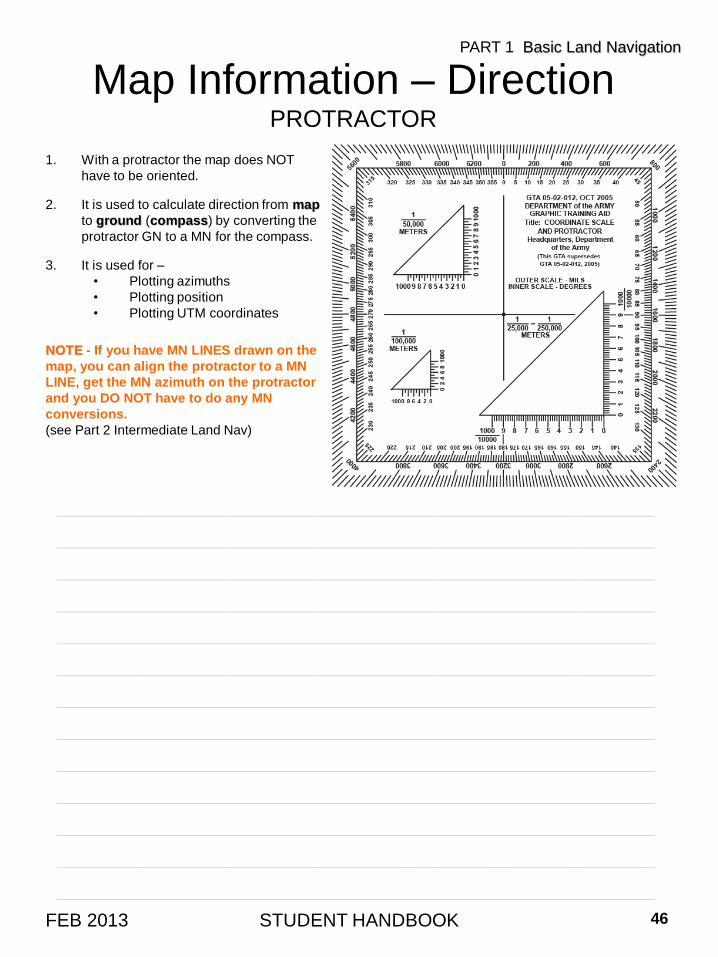
Map Information – DirectionPROTRACTOR
1. With a protractor the map does NOT
have to be oriented.
2. It is used to calculate direction from map
to ground (compass) by converting the
protractor GN to a MN for the compass.
3. It is used for –
• Plotting azimuths
• Plotting position
• Plotting UTM coordinates
NOTE - If you have MN LINES drawn on the
map, you can align the protractor to a MN
LINE, get the MN azimuth on the protractor
and you DO NOT have to do any MN
conversions.
(see Part 2 Intermediate Land Nav)
STUDENT HANDBOOK 46FEB 2013
PART 1 Basic Land Navigation
____________________________________________________________________
____________________________________________________________________
____________________________________________________________________
____________________________________________________________________
____________________________________________________________________
____________________________________________________________________
____________________________________________________________________
____________________________________________________________________
____________________________________________________________________
____________________________________________________________________
____________________________________________________________________
____________________________________________________________________
____________________________________________________________________
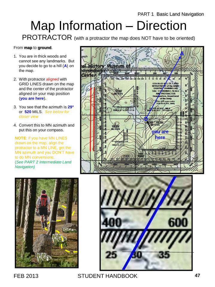
Map Information – DirectionPROTRACTOR (with a protractor the map does NOT have to be oriented)
From map to ground.
1. You are in thick woods and
cannot see any landmarks. But
you decide to go to a hill (A) on
the map.
2. With protractor aligned with
GRID LINES drawn on the map
and the center of the protractor
aligned on your map position
(you are here).
3. You see that the azimuth is 29°
or 520 MILS. See below for
closer view
4. Convert this to MN azimuth and
put this on your compass.
NOTE: If you have MN LINES
drawn on the map, align the
protractor to a MN LINE, get the
MN azimuth and you DON’T have
to do MN conversions.
(See PART 2 Intermediate Land
Navigation)
STUDENT HANDBOOK 47FEB 2013
PART 1 Basic Land Navigation
you are
here
A
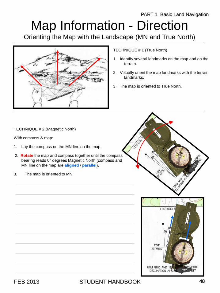
Map Information - DirectionOrienting the Map with the Landscape (MN and True North)
TECHNIQUE # 1 (True North)
1. Identify several landmarks on the map and on the
terrain.
2. Visually orient the map landmarks with the terrain
landmarks.
3. The map is oriented to True North.
TECHNIQUE # 2 (Magnetic North)
With compass & map:
1. Lay the compass on the MN line on the map.
2. Rotate the map and compass together until the compass
bearing reads 0° degrees Magnetic North (compass and
MN line on the map are aligned / parallel).
3. The map is oriented to MN.
STUDENT HANDBOOK 48FEB 2013
PART 1 Basic Land Navigation
____________________________________________
____________________________________________
____________________________________________
____________________________________________
____________________________________________
____________________________________________
____________________________________________
____________________________________________
____________________________________________
____________________________________________
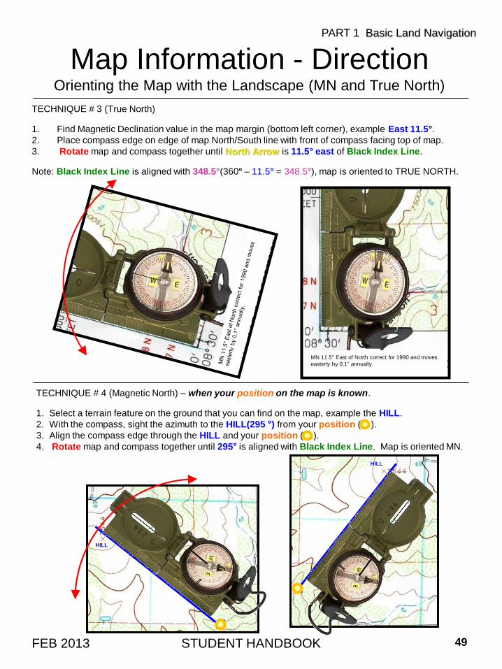
Map Information - DirectionOrienting the Map with the Landscape (MN and True North)
TECHNIQUE # 3 (True North)
1. Find Magnetic Declination value in the map margin (bottom left corner), example East 11.5°.
2. Place compass edge on edge of map North/South line with front of compass facing top of map.
3. Rotate map and compass together until North Arrow is 11.5° east of Black Index Line.
Note: Black Index Line is aligned with 348.5°(360° – 11.5° = 348.5°), map is oriented to TRUE NORTH.
STUDENT HANDBOOK 49FEB 2013
PART 1 Basic Land Navigation
MN 11.5° East of North correct for 1990 and moves
easterly by 0.1° annually.
TECHNIQUE # 4 (Magnetic North) – when your position on the map is known.
1. Select a terrain feature on the ground that you can find on the map, example the HILL.
2. With the compass, sight the azimuth to the HILL(295 °) from your position ( ).
3. Align the compass edge through the HILL and your position ( ).
4. Rotate map and compass together until 295° is aligned with Black Index Line. Map is oriented MN.
HILL
HILL
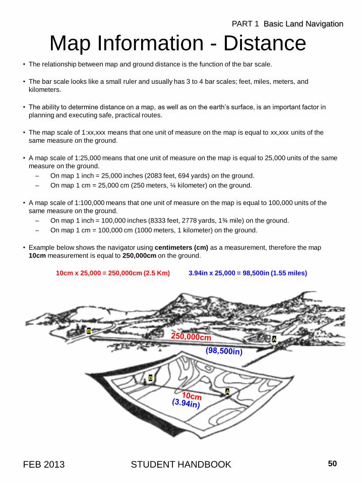
Map Information - Distance• The relationship between map and ground distance is the function of the bar scale.
• The bar scale looks like a small ruler and usually has 3 to 4 bar scales; feet, miles, meters, and
kilometers.
• The ability to determine distance on a map, as well as on the earth’s surface, is an important factor in
planning and executing safe, practical routes.
• The map scale of 1:xx,xxx means that one unit of measure on the map is equal to xx,xxx units of the
same measure on the ground.
• A map scale of 1:25,000 means that one unit of measure on the map is equal to 25,000 units of the same
measure on the ground.
– On map 1 inch = 25,000 inches (2083 feet, 694 yards) on the ground.
– On map 1 cm = 25,000 cm (250 meters, ¼ kilometer) on the ground.
• A map scale of 1:100,000 means that one unit of measure on the map is equal to 100,000 units of the
same measure on the ground.
– On map 1 inch = 100,000 inches (8333 feet, 2778 yards, 1¾ mile) on the ground.
– On map 1 cm = 100,000 cm (1000 meters, 1 kilometer) on the ground.
• Example below shows the navigator using centimeters (cm) as a measurement, therefore the map
10cm measurement is equal to 250,000cm on the ground.
10cm x 25,000 = 250,000cm (2.5 Km) 3.94in x 25,000 = 98,500in (1.55 miles)
STUDENT HANDBOOK 50FEB 2013
PART 1 Basic Land Navigation
A
B
A
B
Map Information - Position• Finding one’s position on a map in the usual sense, such as at the intersection of two compass
bearings, is more a matter of compass technique than of map reading skills. . . BUT . . .
• It is possible to locate your POSITION on a map without a compass, by land feature and map
association.
• It is IMPOSSIBLE TO BE TOTALLY LOST. Finding your location is a process of narrowing down the
options until you can determine a point on a map.
– By determining the lay of the land and finding prominent features, then relating them to your
map, the narrowing-down process will not take long.
– Landmarks can be anything that you recognize as being on the map. Classically these are
hill tops, but you can use the intersection of two roads, a building such as a power grid sub-
station, the abrupt edge of a ridge, the edge of an island, the bend in a trail, anything that you
can recognize as being on the map and that you can see.
• There is a second dimension to establishing position which does depend on map reading skills. This
is the vertical dimension. On a map it is referred to as “relief”.
– Knowledge of the relief of an area is extremely important to a wilderness navigator.
– The most graphic technique ever devised to show relief information is the contour line.
– If you were to walk a contour line you would never go down hill and never up hill, and
eventually you would arrive back where you started.
• Navigation is not about finding yourself after you are lost (although that’s what happens sometimes);
navigation is about keeping track of your POSITION as you move away from a known point. As you
move you have to remain cognizant of the terrain you are leaving, of the terrain you are passing, and
of the terrain that is coming up.
STUDENT HANDBOOK 51FEB 2013
PART 1 Basic Land Navigation
____________________________________________________________________
____________________________________________________________________
____________________________________________________________________
____________________________________________________________________
____________________________________________________________________
____________________________________________________________________
____________________________________________________________________
____________________________________________________________________
____________________________________________________________________
____________________________________________________________________
Map Information - Identification• The identification of significant features, both natural and man-made, is partly a matter of knowing
the language of maps.
– One category of map language is lines. In addition to showing contour relief, lines are used
to portray roads, trails, railroads, power lines, and drainage features.
– Another category of map language is composed of various picture symbols.
– A third part of map language is color.
• If part of identification is in knowing the language of maps, the rest is a problem of interpretation.
What is the relationship among certain lines, symbols, and colors?
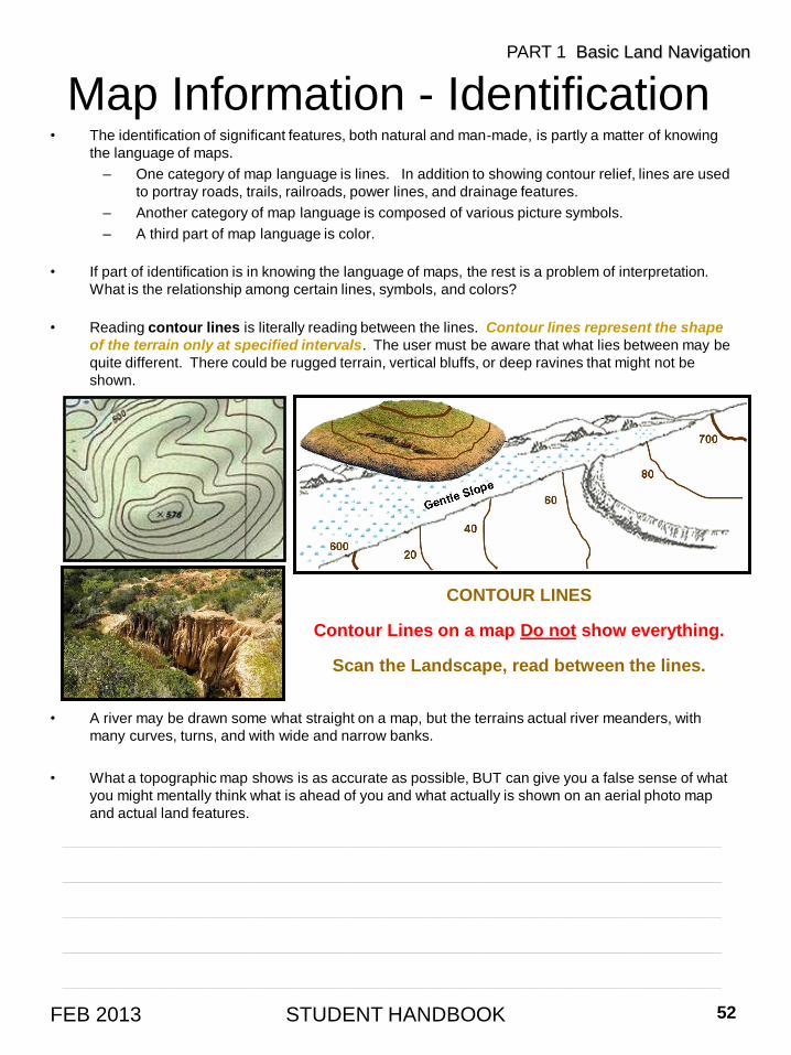
• Reading contour lines is literally reading between the lines. Contour lines represent the shape
of the terrain only at specified intervals. The user must be aware that what lies between may be
quite different. There could be rugged terrain, vertical bluffs, or deep ravines that might not be
shown.
• A river may be drawn some what straight on a map, but the terrains actual river meanders, with
many curves, turns, and with wide and narrow banks.
• What a topographic map shows is as accurate as possible, BUT can give you a false sense of what
you might mentally think what is ahead of you and what actually is shown on an aerial photo map
and actual land features.
STUDENT HANDBOOK 52FEB 2013
PART 1 Basic Land Navigation
CONTOUR LINES
Contour Lines on a map Do not show everything.
Scan the Landscape, read between the lines.
____________________________________________________________________
____________________________________________________________________
____________________________________________________________________
____________________________________________________________________
____________________________________________________________________
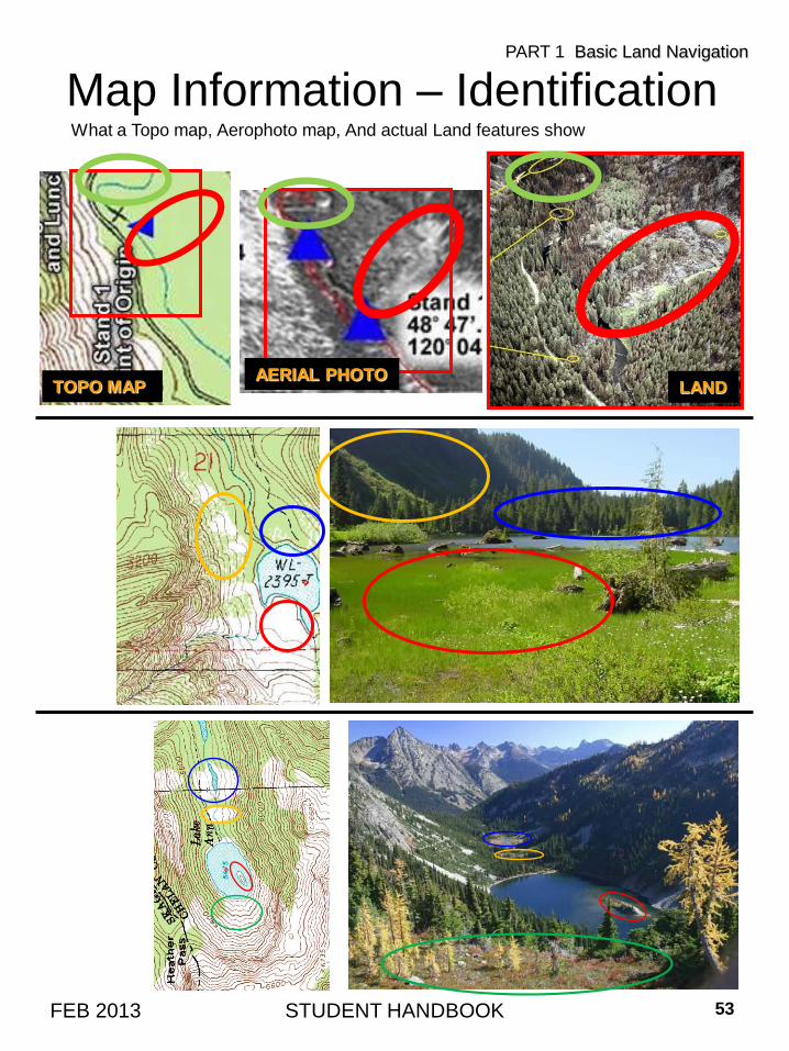
What a Topo map, Aerophoto map, And actual Land features show
Map Information – Identification
STUDENT HANDBOOK 53FEB 2013
PART 1 Basic Land Navigation
LANDAERIAL PHOTO
TOPO MAP
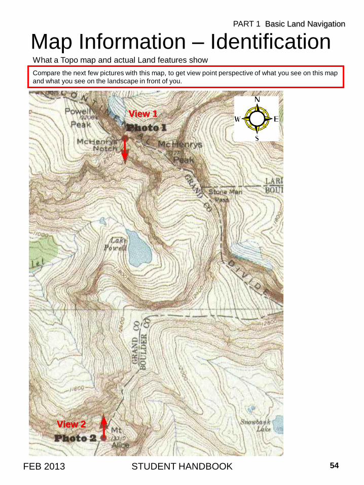
Compare the next few pictures with this map, to get view point perspective of what you see on this map
and what you see on the landscape in front of you.
STUDENT HANDBOOK 54FEB 2013
What a Topo map and actual Land features show
Map Information – IdentificationPART 1 Basic Land Navigation
View 1
View 2

STUDENT HANDBOOK 55FEB 2013
What a Topo map and actual Land features show
Map Information – IdentificationPART 1 Basic Land Navigation
View 1
View 2
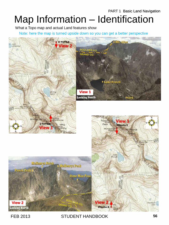
Note: here the map is turned upside down so you can get a better perspective
STUDENT HANDBOOK 56FEB 2013
What a Topo map and actual Land features show
Map Information – IdentificationPART 1 Basic Land Navigation
View 1
View 2
View 1
View 2
View 1
View 2
Map Folding and Map Care• Maps should be correctly folded.
– Maps should be folded to make them small enough to be carried and still be available for use
without having to unfold them entirely.
– After a map has been folded it should be placed in a folder for protection. This will prevent
the corners and edges of the map from wearing out and tearing easily when opened.
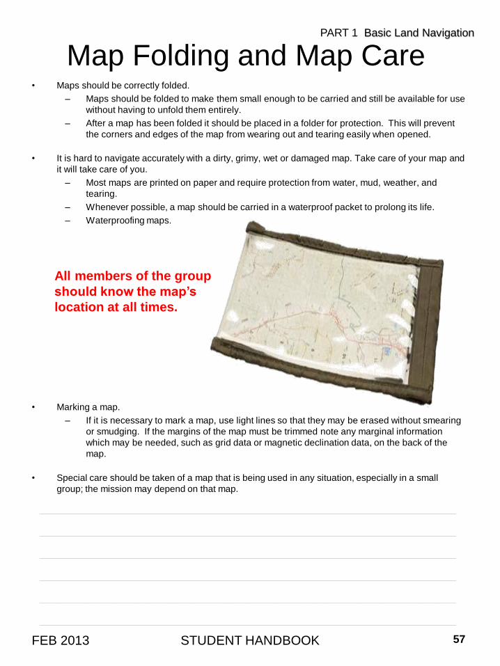
• It is hard to navigate accurately with a dirty, grimy, wet or damaged map. Take care of your map and
it will take care of you.
– Most maps are printed on paper and require protection from water, mud, weather, and
tearing.
– Whenever possible, a map should be carried in a waterproof packet to prolong its life.
– Waterproofing maps.
• Marking a map.
– If it is necessary to mark a map, use light lines so that they may be erased without smearing
or smudging. If the margins of the map must be trimmed note any marginal information
which may be needed, such as grid data or magnetic declination data, on the back of the
map.
• Special care should be taken of a map that is being used in any situation, especially in a small
group; the mission may depend on that map.
All members of the group
should know the map’s
location at all times.
STUDENT HANDBOOK 57FEB 2013
PART 1 Basic Land Navigation
____________________________________________________________________
____________________________________________________________________
____________________________________________________________________
____________________________________________________________________
____________________________________________________________________
____________________________________________________________________
____________________________________________________________________
____________________________________________________________________
____________________________________________________________________
____________________________________________________________________
____________________________________________________________________
____________________________________________________________________
____________________________________________________________________
WELCOME TO LAND NAVIGATION CLASS
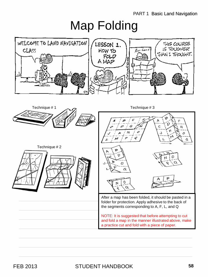
Map Folding
STUDENT HANDBOOK 58FEB 2013
PART 1 Basic Land Navigation
Technique # 2
Technique # 1 Technique # 3
After a map has been folded, it should be pasted in a
folder for protection. Apply adhesive to the back of
the segments corresponding to A, F, L, and Q
NOTE: It is suggested that before attempting to cut
and fold a map in the manner illustrated above, make
a practice cut and fold with a piece of paper.
THE END OF
LAND NAVIGATION
PRESENTATION
PART 1
www.landnavigation.org
www.landnavigation.weebly.com
STUDENT HANDBOOK 59FEB 2013
PART 1 Basic Land Navigation