Embed Size (px)
Citation preview
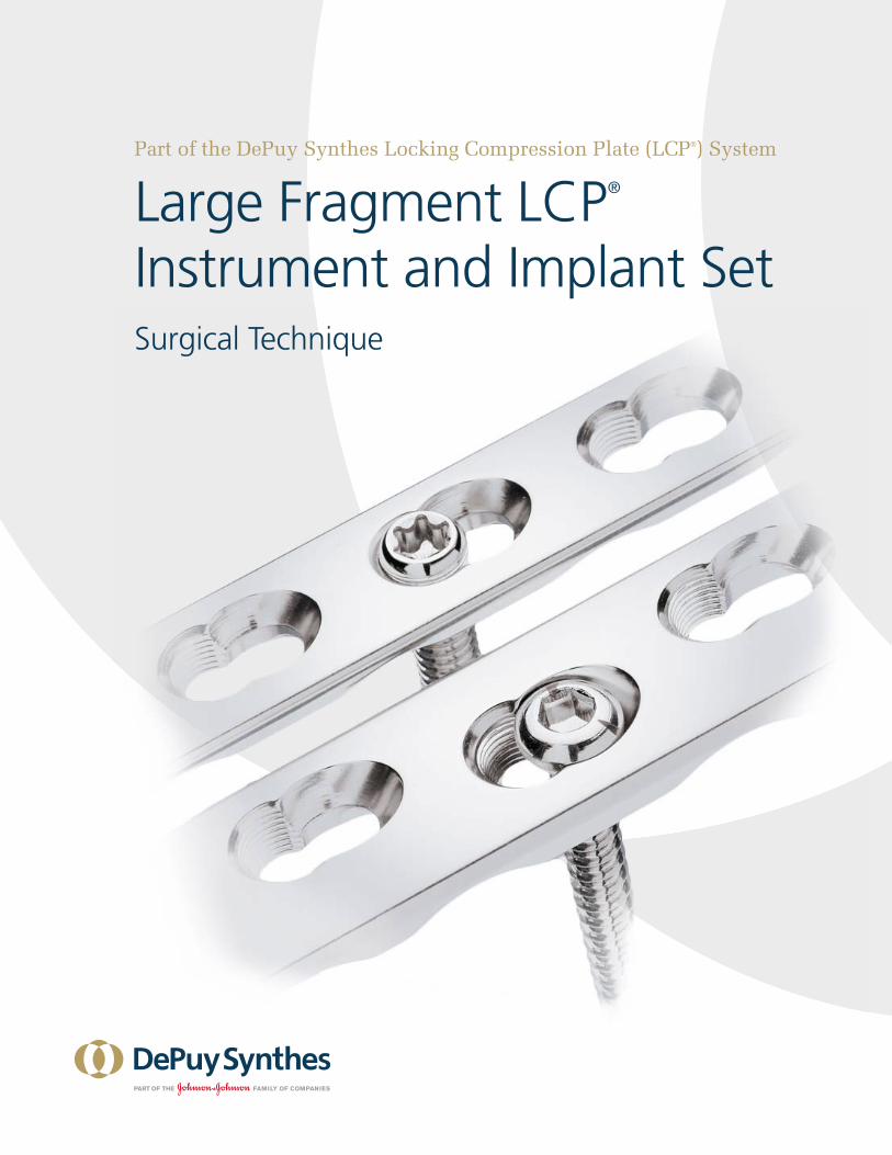
Part of the DePuy Synthes Locking Compression Plate (LCP®) System
Large Fragment LCP® Instrument and Implant SetSurgical Technique

Large Fragment LCP® Instrument and Implant Set Surgical Technique DePuy Synthes 1
Introduction
Surgical Technique
Product Information
Large Fragment LCP Instrument and Implant Set 2
Locking Screws 4 AO Principles 5
Indications 6 Fixation Principles—Conventional Plating 7 Fixation Principles—Locked Plating 9
Combining Conventional and Locked Plating Techniques 10
Screw Selection 11
Preparation and Reduction 12
Screw Insertion 14
Screw Placement Verification 17
Postoperative Treatment 18 Implant Removal 18
Implants 19
Instruments 21
Set Lists 23
Discontinued Product 29
Table of Contents
MR Information The Large Fragment LCP Implant Set has not been evaluated for safety and compatibility in the MR environment. It has not been tested for heating, migration or image artifact in the MR environment. The safety of the Large Fragment LCP Implant Set in the MR environment is unknown. Scanning a patient who has this device may result in patient injury.
Image intensifier control
2 DePuy Synthes Large Fragment LCP® Instrument and Implant Set Surgical Technique
1. Rüedi TP, et al, ed., AO Principles of Fracture Management, New York: Thieme. 2000.
The aim of any surgical fracture treatment is to reconstruct the anatomy and restore its function. According to the AO, internal fixation is distinguished by anatomic reduction, stable fixation, preservation of blood supply and early, functional mobilization. Plate and screw osteosynthesis has been established as clinically beneficial for quite some time. Clinical results have improved by using internal fixation with angular stability (internal fixators) in complicated fractures and in osteopenic bone.
The DePuy Synthes Locking Compression Plate (LCP®) System is part of a Stainless Steel and Titanium Plate and Screw System that merges locking screw technology with conventional plating techniques. The LCP System has many similarities to conventional plate fixation methods, but with a few important improvements. Locking screws provide the ability to create a fixed-angle construct while utilizing familiar AO plating techniques. A fixed-angle construct provides improved fixation in osteopenic bone or multifragment fractures where traditional screw purchase is compromised. LCP Plate constructs do not rely on plate-to-bone compression to maintain stability, but function similarly to multiple small multiangled blade plates.
The following points distinguish treatment using Locking Compression Plate technology:• Allows fracture treatment using conventional plating
with conventional cortex or cancellous bone screws;• Allows fracture treatment using locked plating with
bicortical or unicortical locking screws;• Permits the combination of conventional and locking
screw techniques.
Note: The LCP System applies to many different plate types and is therefore suitable for a large number of fracture types. For that reason, this technique guide does not deal with any specific fracture type. For more information, please refer to AO Principles of Fracture Management,1 to AO courses (www.ao-asif.ch), and to the appropriate plate-specific technique guide.
Large Fragment LCP Instrument and Implant Set
Large Fragment LCP® Instrument and Implant Set Surgical Technique DePuy Synthes 3
cd
ab
StarDrive Recess
Self-tapping flutes
Cortical thread profile
Locking threads mate with the plates
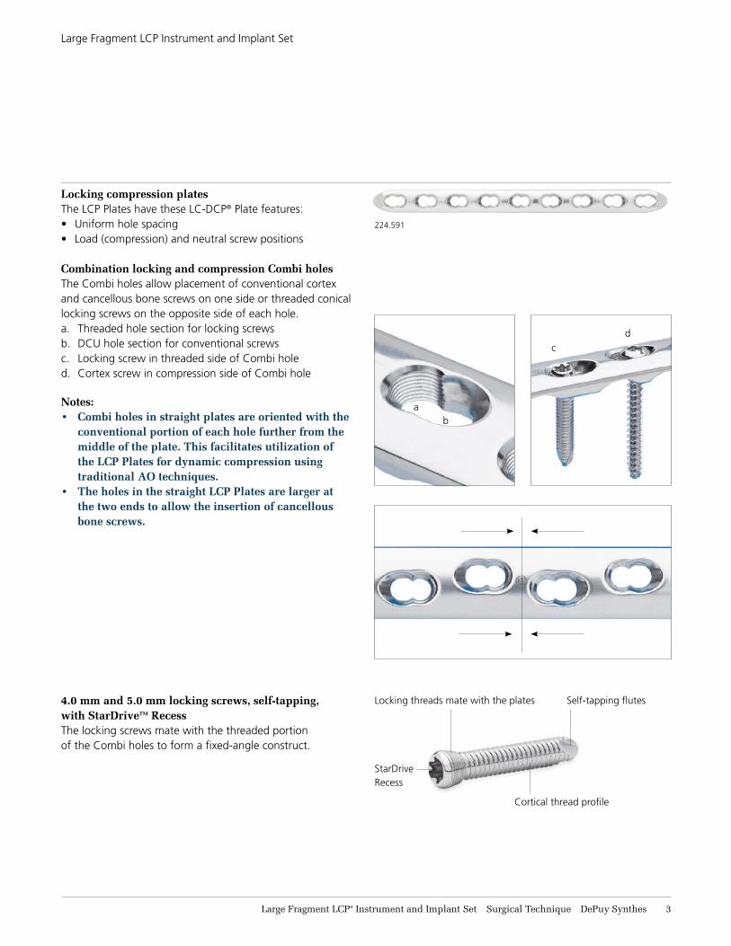
Locking compression platesThe LCP Plates have these LC-DCP® Plate features:• Uniform hole spacing• Load (compression) and neutral screw positions
Combination locking and compression Combi holesThe Combi holes allow placement of conventional cortex and cancellous bone screws on one side or threaded conical locking screws on the opposite side of each hole.a. Threaded hole section for locking screwsb. DCU hole section for conventional screwsc. Locking screw in threaded side of Combi holed. Cortex screw in compression side of Combi hole
Notes: • Combi holes in straight plates are oriented with the
conventional portion of each hole further from the middle of the plate. This facilitates utilization of the LCP Plates for dynamic compression using traditional AO techniques.
• The holes in the straight LCP Plates are larger at the two ends to allow the insertion of cancellous bone screws.
4.0 mm and 5.0 mm locking screws, self-tapping, with StarDriveTM RecessThe locking screws mate with the threaded portion of the Combi holes to form a fixed-angle construct.
224.591
Large Fragment LCP Instrument and Implant Set
4 DePuy Synthes Large Fragment LCP® Instrument and Implant Set Surgical Technique
a
b
a. Bicortical screws require two (2) cortices to achieve stability b. Unicortical screws utilize the locked screwhead and the near
cortex to achieve stability
Locking screw designThe screw design has been modified, from standard 4.5 mm cortex screw design, to enhance fixation and facilitate the surgical procedure.
New features include:Conical screwheadThe conical head facilitates alignment of the locking screw in the threaded plate hole to provide a fixed-angle connection between the screw and the plate.
Large core diameterThe large core diameter improves bending and shear strength of the screw, and distributes the load over a larger area in the bone.
Thread profileThe shallow thread profile of the locking screws results from the larger core diameter, and is acceptable because locking screws do not rely solely on screw purchase in the bone to maintain stability.
Drive mechanismThe StarDrive Recess provides improved torque transmission to the screw, while retaining the screw without the use of a holding sleeve.
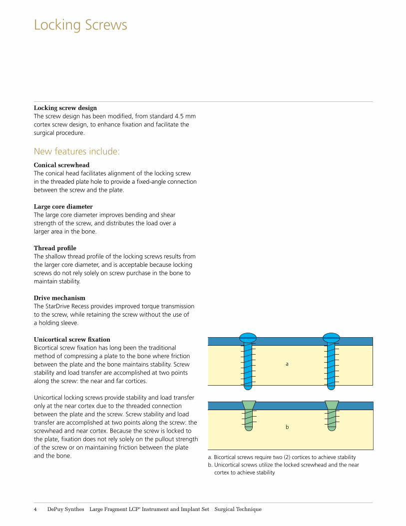
Unicortical screw fixationBicortical screw fixation has long been the traditional method of compressing a plate to the bone where friction between the plate and the bone maintains stability. Screw stability and load transfer are accomplished at two points along the screw: the near and far cortices.
Unicortical locking screws provide stability and load transfer only at the near cortex due to the threaded connection between the plate and the screw. Screw stability and load transfer are accomplished at two points along the screw: the screwhead and near cortex. Because the screw is locked to the plate, fixation does not rely solely on the pullout strength of the screw or on maintaining friction between the plate and the bone.
Locking Screws
Large Fragment LCP® Instrument and Implant Set Surgical Technique DePuy Synthes 5
AO Principles
1
4
2
3
4_Priciples_03.pdf 1 05.07.12 12:08
4 DePuy Synthes Expert Lateral Femoral Nail Surgical Technique
AO PRINCIPLES
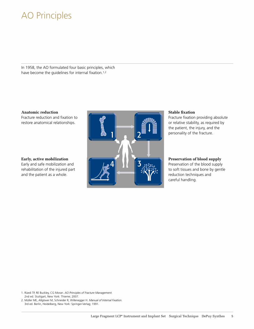
In 1958, the AO formulated four basic principles, which have become the guidelines for internal fixation1, 2.
1 Müller ME, M Allgöwer, R Schneider, H Willenegger. Manual of Internal Fixation. 3rd ed. Berlin Heidelberg New York: Springer. 1991.
2 Rüedi TP, RE Buckley, CG Moran. AO Principles of Fracture Management. 2nd ed. Stuttgart, New York: Thieme. 2007.
Anatomic reductionFracture reduction and fixation to restore anatomical relationships.
Early, active mobilizationEarly and safe mobilization and rehabilitation of the injured part and the patient as a whole.
Stable fixationFracture fixation providing abso-lute or relative stability, as required by the patient, the injury, and the personality of the fracture.
Preservation of blood supplyPreservation of the blood supply to soft tissues and bone by gentle reduction techniques and careful handling.
In 1958, the AO formulated four basic principles, which have become the guidelines for internal fixation.1,2
Anatomic reductionFracture reduction and fixation to restore anatomical relationships.
Early, active mobilizationEarly and safe mobilization and rehabilitation of the injured part and the patient as a whole.
Stable fixationFracture fixation providing absolute or relative stability, as required by the patient, the injury, and the personality of the fracture.
Preservation of blood supplyPreservation of the blood supply to soft tissues and bone by gentle reduction techniques and careful handling.
1. Rüedi TP, RE Buckley, CG Moran. AO Principles of Fracture Management. 2nd ed. Stuttgart, New York: Thieme; 2007.
2. Müller ME, Allgöwer M, Schneider R, Willenegger H. Manual of Internal Fixation. 3rd ed. Berlin, Heidelberg, New York: Springer-Verlag; 1991.
6 DePuy Synthes Large Fragment LCP® Instrument and Implant Set Surgical Technique
Indications
The Synthes Locking Compression Plates—Narrow and broad, are intended for fixation of various long bones, such as the humerus, femur, and tibia. They are also for use in fixation of periprosthetic fractures, osteopenic bone, and nonunions or malunions.
The Synthes Locking Compression Plates—T-Plates are intended to buttress metaphyseal fractures of the proximal humerus, medial tibial plateau, and distal tibia. They are also for use in fixation of osteopenic bone and fixation of nonunions and malunions.
The Synthes LCP Proximal Tibia Plate is intended for treatment of nonunions, malunions, and fractures of the proximal tibia, including simple, comminuted, lateral wedge, depression, medial wedge, bicondylar, combinations of lateral wedge and depression, periprosthetic, and fractures with associated shaft fractures.
The Synthes 3.5 mm/4.5 mm LCP Medial Proximal Tibia Plates are intended to buttress metaphyseal fractures of the medial tibia plateau, split-type fractures of the medial tibia plateau, medial split fractures with associated depressions, and split or depression fractures of the medial tibia plateau. The plates may also be used for fixation of the proximal quarter (lateral and medial) of the tibia as well as segmental fractures of the proximal tibia. The 4.5 mm version may also be used for fixation of nonunions and malunions of the medial proximal tibia and tibia shaft, as well as opening and closing wedge tibial osteotomies.
Large Fragment LCP® Instrument and Implant Set Surgical Technique DePuy Synthes 7
Fixation Principles—Conventional Plating
The following pages show the biomechanical features of conventional plating techniques, locked or bridge plating techniques, and a combination of both.
Note: Please refer also to the AO Principles of Fracture Management,1 to AO courses (www.ao-asif.ch), and to the corresponding special literature.
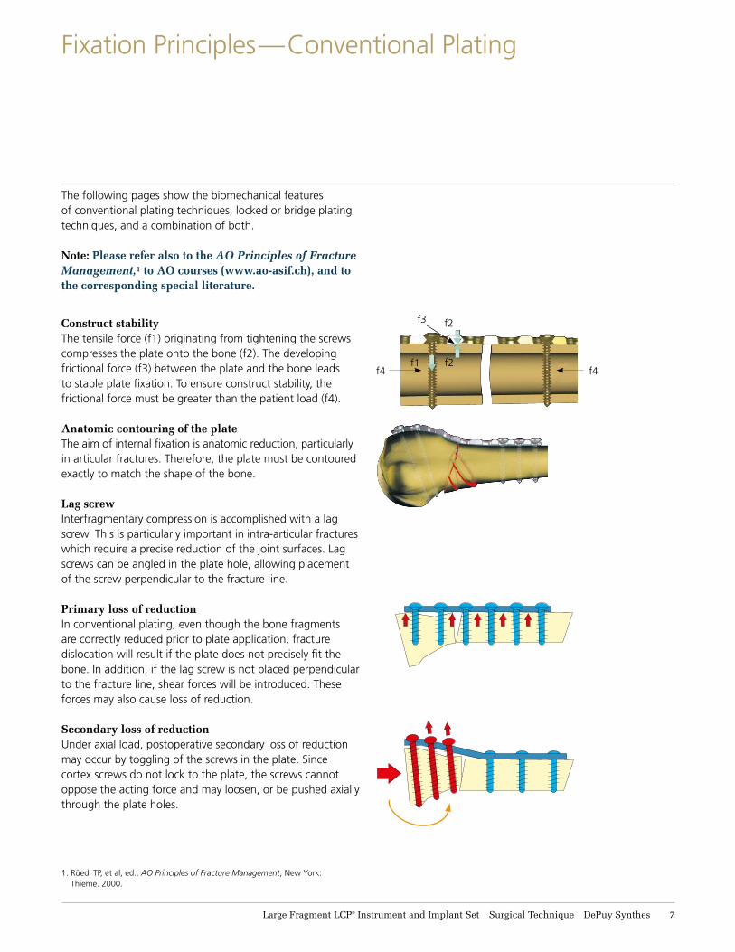
Construct stabilityThe tensile force (f1) originating from tightening the screws compresses the plate onto the bone (f2). The developing frictional force (f3) between the plate and the bone leads to stable plate fixation. To ensure construct stability, the frictional force must be greater than the patient load (f4).
Anatomic contouring of the plateThe aim of internal fixation is anatomic reduction, particularly in articular fractures. Therefore, the plate must be contoured exactly to match the shape of the bone.
Lag screwInterfragmentary compression is accomplished with a lag screw. This is particularly important in intra-articular fractures which require a precise reduction of the joint surfaces. Lag screws can be angled in the plate hole, allowing placement of the screw perpendicular to the fracture line.
Primary loss of reductionIn conventional plating, even though the bone fragments are correctly reduced prior to plate application, fracture dislocation will result if the plate does not precisely fit the bone. In addition, if the lag screw is not placed perpendicular to the fracture line, shear forces will be introduced. These forces may also cause loss of reduction.
Secondary loss of reductionUnder axial load, postoperative secondary loss of reduction may occur by toggling of the screws in the plate. Since cortex screws do not lock to the plate, the screws cannot oppose the acting force and may loosen, or be pushed axially through the plate holes.
f1f4 f4
f2
f2
f3
1. Rüedi TP, et al, ed., AO Principles of Fracture Management, New York: Thieme. 2000.
8 DePuy Synthes Large Fragment LCP® Instrument and Implant Set Surgical Technique
Fixation Principles—Conventional Plating
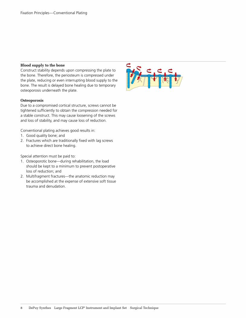
Blood supply to the boneConstruct stability depends upon compressing the plate to the bone. Therefore, the periosteum is compressed under the plate, reducing or even interrupting blood supply to the bone. The result is delayed bone healing due to temporary osteoporosis underneath the plate.
OsteoporosisDue to a compromised cortical structure, screws cannot be tightened sufficiently to obtain the compression needed for a stable construct. This may cause loosening of the screws and loss of stability, and may cause loss of reduction.
Conventional plating achieves good results in:1. Good quality bone; and2. Fractures which are traditionally fixed with lag screws
to achieve direct bone healing.
Special attention must be paid to:1. Osteoporotic bone—during rehabilitation, the load
should be kept to a minimum to prevent postoperative loss of reduction; and
2. Multifragment fractures—the anatomic reduction may be accomplished at the expense of extensive soft tissue trauma and denudation.
Large Fragment LCP® Instrument and Implant Set Surgical Technique DePuy Synthes 9
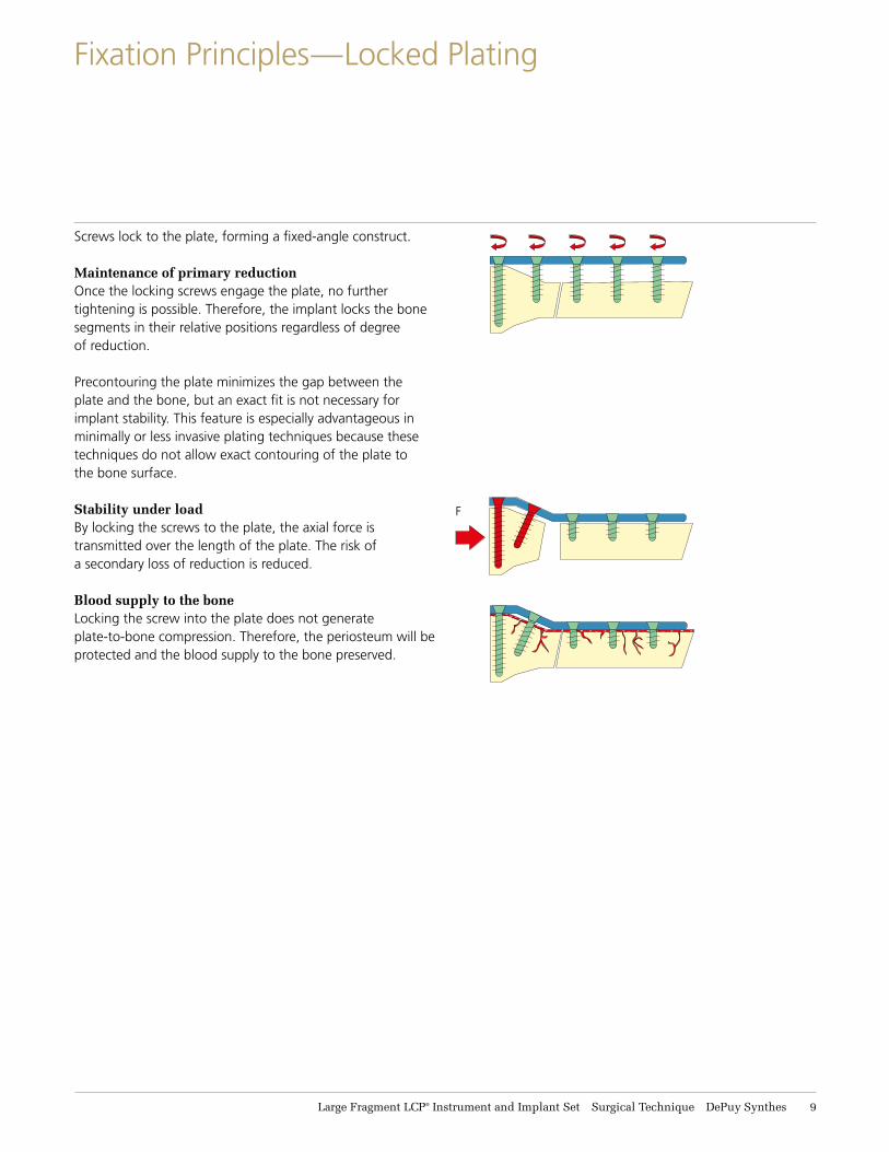
Fixation Principles—Locked Plating
Screws lock to the plate, forming a fixed-angle construct.
Maintenance of primary reductionOnce the locking screws engage the plate, no further tightening is possible. Therefore, the implant locks the bone segments in their relative positions regardless of degree of reduction.
Precontouring the plate minimizes the gap between the plate and the bone, but an exact fit is not necessary for implant stability. This feature is especially advantageous in minimally or less invasive plating techniques because these techniques do not allow exact contouring of the plate to the bone surface.
Stability under loadBy locking the screws to the plate, the axial force is transmitted over the length of the plate. The risk of a secondary loss of reduction is reduced.
Blood supply to the boneLocking the screw into the plate does not generate plate-to-bone compression. Therefore, the periosteum will be protected and the blood supply to the bone preserved.
F
11 DePuy Synthes Large Fragment LCP® Instrument and Implant Set Surgical Technique
Combining Conventional and Locked Plating Techniques— The Locking Compression Plate (LCP) System
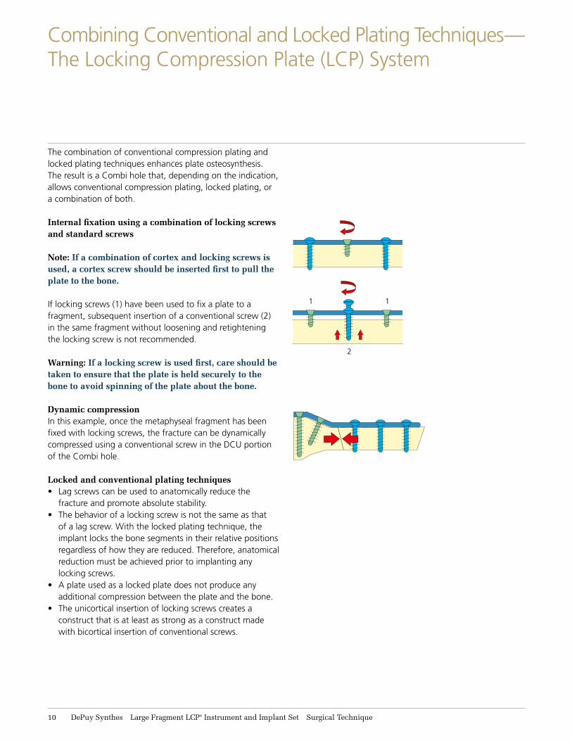
The combination of conventional compression plating and locked plating techniques enhances plate osteosynthesis. The result is a Combi hole that, depending on the indication, allows conventional compression plating, locked plating, or a combination of both.
Internal fixation using a combination of locking screws and standard screws
Note: If a combination of cortex and locking screws is used, a cortex screw should be inserted first to pull the plate to the bone.
If locking screws (1) have been used to fix a plate to a fragment, subsequent insertion of a conventional screw (2) in the same fragment without loosening and retightening the locking screw is not recommended.
Warning: If a locking screw is used first, care should be taken to ensure that the plate is held securely to the bone to avoid spinning of the plate about the bone.
Dynamic compressionIn this example, once the metaphyseal fragment has been fixed with locking screws, the fracture can be dynamically compressed using a conventional screw in the DCU portion of the Combi hole.
Locked and conventional plating techniques• Lag screws can be used to anatomically reduce the
fracture and promote absolute stability.• The behavior of a locking screw is not the same as that
of a lag screw. With the locked plating technique, the implant locks the bone segments in their relative positions regardless of how they are reduced. Therefore, anatomical reduction must be achieved prior to implanting any locking screws.
• A plate used as a locked plate does not produce any additional compression between the plate and the bone.
• The unicortical insertion of locking screws creates a construct that is at least as strong as a construct made with bicortical insertion of conventional screws.
1 1
2
Large Fragment LCP® Instrument and Implant Set Surgical Technique DePuy Synthes 11
Screw Selection
Locked Plate and Screw Testing (40 lb/ft3 foam)
Load
(N)
800
700
600
500
400
300
200
100
0
0 1 2 3 4 5 6 7 8
�
�
�� �
�
�
��
�
5.0 mm locking bicortical, 3 each4.0 mm locking bicortical, 3 each4.5 mm cortex, 2 each and 5.0 mm locking bicortical, 1 each4.5 mm cortex, 3 each4.5 mm cortex, 2 each and 5.0 mm locking unicortical, 1 each4.0 mm locking unicortical, 3 each
�
�
�
�
�
�
�
�
�
Displacement (mm)
Locked Plate and Screw Testing (15 lb/ft3 foam)
Load
(N)
600
500
400
300
200
100
0
Displacement (mm)
0 1 2 3 4 5 6 7 8
�
�
��
�
��
�
�
�
�
�
��
�
�
5.0 mm locking bicortical, 3 each 4.0 mm locking bicortical, 3 each4.5 mm cortex, 2 each and 4.0 mm locking bicortical, 1 each4.5 mm cortex, 3 each4.5 mm cortex, 2 each and 5.0 mm locking unicortical, 1 each 4.0 mm locking unicortical, 3 each
�
�
�
Comparative Bending and Shear Strength of Locking ScrewsRelative to 4.5 mm Cortex Screws
Screw TypePe
rcen
t
300%
250%
200%
150%
100%
50%
0%4.5 mm Cortex
3.2 mm Core Diameter4.0 mm Locking
3.4 mm Core Diameter5.0 mm Locking
4.4 mm Core Diameter
Bending
Shear
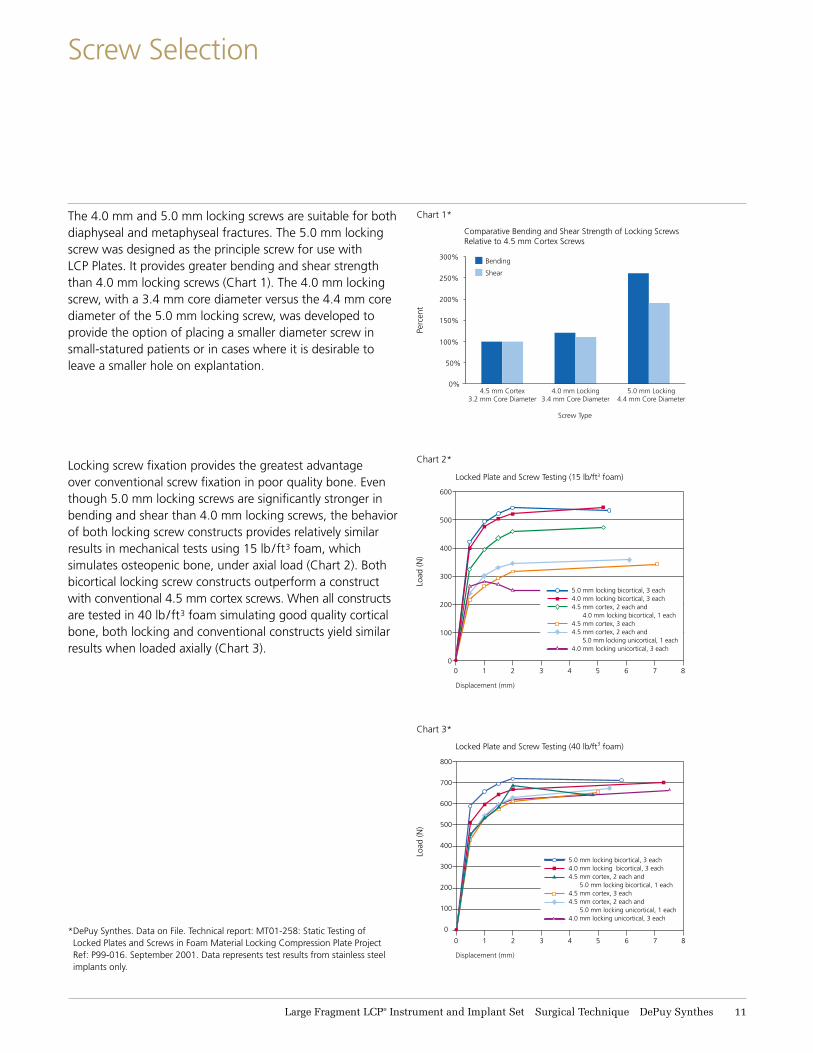
The 4.0 mm and 5.0 mm locking screws are suitable for both diaphyseal and metaphyseal fractures. The 5.0 mm locking screw was designed as the principle screw for use with LCP Plates. It provides greater bending and shear strength than 4.0 mm locking screws (Chart 1). The 4.0 mm locking screw, with a 3.4 mm core diameter versus the 4.4 mm core diameter of the 5.0 mm locking screw, was developed to provide the option of placing a smaller diameter screw in small-statured patients or in cases where it is desirable to leave a smaller hole on explantation.
Locking screw fixation provides the greatest advantage over conventional screw fixation in poor quality bone. Even though 5.0 mm locking screws are significantly stronger in bending and shear than 4.0 mm locking screws, the behavior of both locking screw constructs provides relatively similar results in mechanical tests using 15 lb/ft3 foam, which simulates osteopenic bone, under axial load (Chart 2). Both bicortical locking screw constructs outperform a construct with conventional 4.5 mm cortex screws. When all constructs are tested in 40 lb/ft3 foam simulating good quality cortical bone, both locking and conventional constructs yield similar results when loaded axially (Chart 3).
* DePuy Synthes. Data on File. Technical report: MT01-258: Static Testing of Locked Plates and Screws in Foam Material Locking Compression Plate Project Ref: P99-016. September 2001. Data represents test results from stainless steel implants only.
Chart 2*
Chart 3*
Chart 1*
12 DePuy Synthes Large Fragment LCP® Instrument and Implant Set Surgical Technique
Preparation and Reduction
1. Plate selectionThe plates are available in various lengths and configurations similar to the DePuy Synthes basic plate set. If necessary, use a bending template to determine plate length and configuration.
2. ContouringUse the current bending instruments to contour the locking compression plate to the anatomy.
Note: The plate holes have been designed to accept some degree of deformation. When bending the plate, place the bending irons on two consecutive holes. This ensures that the threaded holes will not be distorted. Significant distortion of the locking holes will reduce locking effectiveness.
Precautions: • Reverse bending or use of the incorrect instrumentation
for bending may weaken the plate and lead to premature plate failure (e.g. breakage). Do not bend the plate beyond what is required to match the anatomy.
• Do not bend the plate at the level of the holes.
Note: Please refer also to the AO Principles of Fracture Management.1
Precautions:• Instruments and screws may have sharp edges or
moving joints that may pinch or tear user’s glove or skin.
• Handle devices with care and dispose of worn bone cutting instruments in an approved sharps container.
1. Rüedi TP, et al, ed., AO Principles of Fracture Management, New York: Thieme. 2000.
Large Fragment LCP® Instrument and Implant Set Surgical Technique DePuy Synthes 13
3. Reduction and temporary plate placement
Instruments
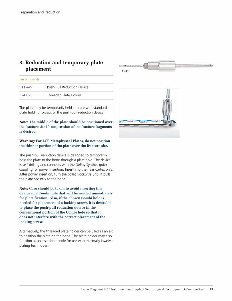
311.449 Push-Pull Reduction Device
324.075 Threaded Plate Holder
The plate may be temporarily held in place with standard plate holding forceps or the push-pull reduction device.
Note: The middle of the plate should be positioned over the fracture site if compression of the fracture fragments is desired.
Warning: For LCP Metaphyseal Plates, do not position the thinner portion of the plate over the fracture site.
The push-pull reduction device is designed to temporarily hold the plate to the bone through a plate hole. The device is self-drilling and connects with the DePuy Synthes quick coupling for power insertion. Insert into the near cortex only. After power insertion, turn the collet clockwise until it pulls the plate securely to the bone.
Note: Care should be taken to avoid inserting this device in a Combi hole that will be needed immediately for plate fixation. Also, if the chosen Combi hole is needed for placement of a locking screw, it is desirable to place the push-pull reduction device in the conventional portion of the Combi hole so that it does not interfere with the correct placement of the locking screw.
Alternatively, the threaded plate holder can be used as an aid to position the plate on the bone. The plate holder may also function as an insertion handle for use with minimally invasive plating techniques.
Preparation and Reduction
311.449
14 DePuy Synthes Large Fragment LCP® Instrument and Implant Set Surgical Technique
Screw Insertion
4. Screw insertion
Instrument
323.46 4.5 mm Universal Drill Guide
Determine whether conventional cortex screws, cancellous bone screws, or locking screws will be used for fixation. A combination of all may be used.
Note: If a combination of cortex, cancellous and locking screws is used, a conventional screw should be used first to pull the plate to the bone.
Warning: If a locking screw is used first, care should be taken to ensure that the plate is held securely to the bone to avoid spinning of the plate about the bone as the locking screw is tightened to the plate.
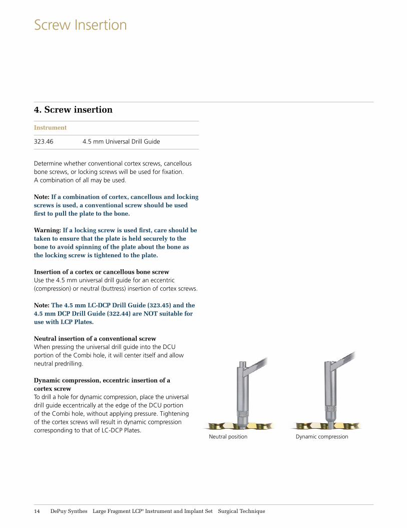
Insertion of a cortex or cancellous bone screwUse the 4.5 mm universal drill guide for an eccentric (compression) or neutral (buttress) insertion of cortex screws.
Note: The 4.5 mm LC-DCP Drill Guide (323.45) and the 4.5 mm DCP Drill Guide (322.44) are NOT suitable for use with LCP Plates.
Neutral insertion of a conventional screwWhen pressing the universal drill guide into the DCU portion of the Combi hole, it will center itself and allow neutral predrilling.
Dynamic compression, eccentric insertion of a cortex screwTo drill a hole for dynamic compression, place the universal drill guide eccentrically at the edge of the DCU portion of the Combi hole, without applying pressure. Tightening of the cortex screws will result in dynamic compression correspond ing to that of LC-DCP Plates.
Neutral position Dynamic compression
Large Fragment LCP® Instrument and Implant Set Surgical Technique DePuy Synthes 15
Screw Insertion
Instruments
310.31 3.2 mm Drill Bit
310.431 4.3 mm Drill Bit
312.445 3.2 mm Threaded Drill Guide (for 4.0 mm screws)
312.449 4.3 mm Threaded Drill Guide (for 5.0 mm screws)
314.118 StarDrive Screwdriver, T25
314.119 StarDrive Screwdriver Shaft, T25, quick coupling
319.10 Depth Gauge
511.771* Torque Limiting Attachment, 4 Nm or 511.774 Torque Limiting Attachment, 4 Nm,
for AO Reaming Coupler
Insertion of 4.0 mm and 5.0 mm locking screws
Note: The locking screw is not a lag screw. Use nonlocking screws when requiring a precise anatomical reduction (e.g., joint surfaces) or interfragmentary compression. Before inserting the first locking screw, perform anatomical reduction and fix the fracture with lag screws, if necessary. After the insertion of locking screws, an anatomical reduction will no longer be possible without loosening the locking screw.
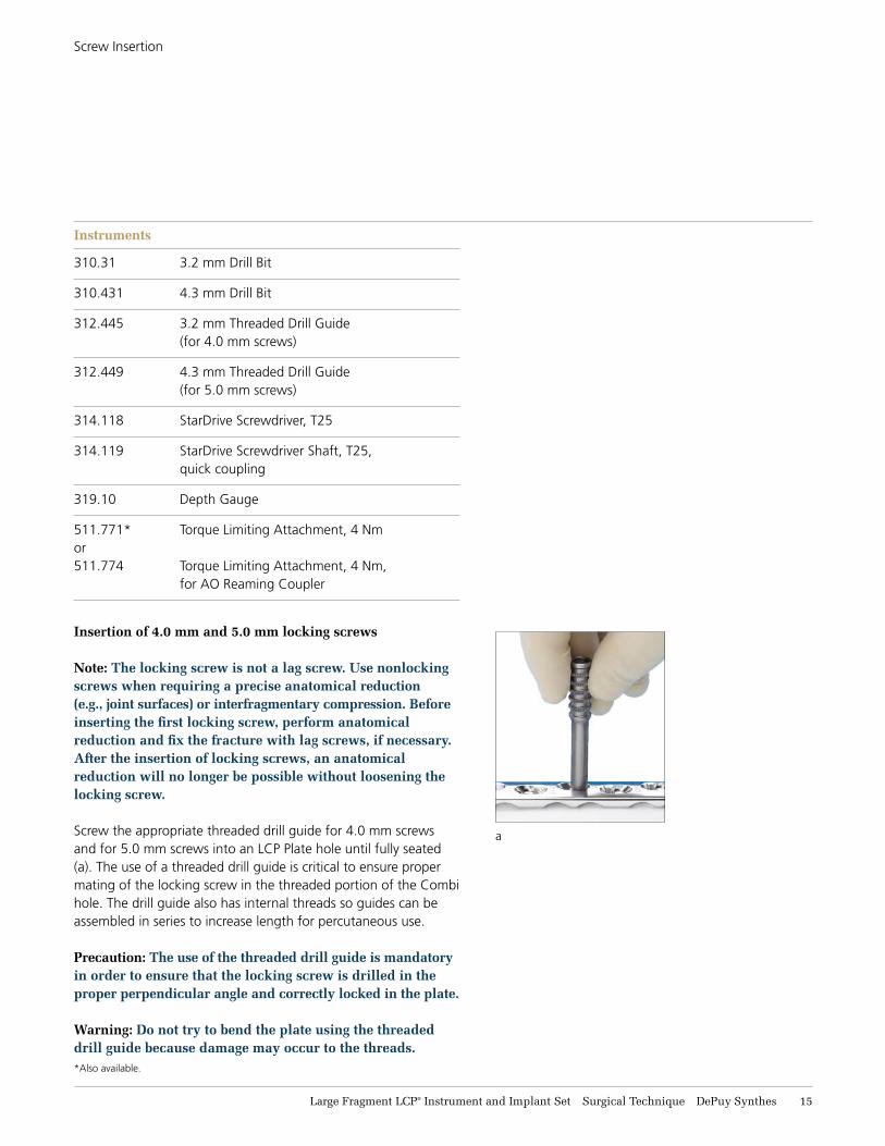
Screw the appropriate threaded drill guide for 4.0 mm screws and for 5.0 mm screws into an LCP Plate hole until fully seated (a). The use of a threaded drill guide is critical to ensure proper mating of the locking screw in the threaded portion of the Combi hole. The drill guide also has internal threads so guides can be assembled in series to increase length for percutaneous use.
Precaution: The use of the threaded drill guide is mandatory in order to ensure that the locking screw is drilled in the proper perpendicular angle and correctly locked in the plate.
Warning: Do not try to bend the plate using the threaded drill guide because damage may occur to the threads.
a
*Also available.
16 DePuy Synthes Large Fragment LCP® Instrument and Implant Set Surgical Technique
4. Screw insertion continued
Notes: • Since the direction of a locking screw is determined
by plate design, final screw position may be verified with a guide wire before insertion. This is especially important when the plate has been contoured or applied in metaphyseal regions around joint surfaces.
• The 5.0 mm cannulated locking screws and 5.0 mm cannulated conical screws for the locking periarticular plating system are compatible with the large fragment LCP Plates.
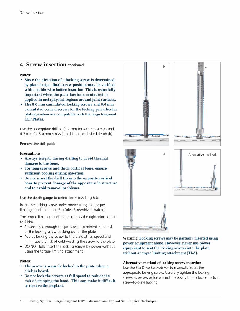
Use the appropriate drill bit (3.2 mm for 4.0 mm screws and 4.3 mm for 5.0 mm screws) to drill to the desired depth (b). Remove the drill guide.
Precautions:• Always irrigate during drilling to avoid thermal
damage to the bone. • For long screws and thick cortical bone, ensure
sufficient cooling during insertion. • Do not insert the drill tip into the opposite cortical
bone to prevent damage of the opposite side structure and to avoid removal problems.
Use the depth gauge to determine screw length (c).
Insert the locking screw under power using the torque limiting attachment and StarDrive Screwdriver shaft (d).
The torque limiting attachment controls the tightening torque to 4 Nm.• Ensures that enough torque is used to minimize the risk
of the locking screw backing out of the plate• Avoids locking the screw to the plate at full speed and
minimizes the risk of cold-welding the screw to the plate• DO NOT fully insert the locking screws by power without
using the torque limiting attachment
Notes: • The screw is securely locked to the plate when a
click is heard.• Do not lock the screws at full speed to reduce the
risk of stripping the head. This can make it difficult to remove the implant.
Screw Insertion
b c
Warning: Locking screws may be partially inserted using power equipment alone. However, never use power equipment to seat the locking screws into the plate without a torque limiting attachment (TLA).
Alternative method of locking screw insertionUse the StarDrive Screwdriver to manually insert the appropriate locking screw. Carefully tighten the locking screw, as excessive force is not necessary to produce effective screw-to-plate locking.
d Alternative method
Large Fragment LCP® Instrument and Implant Set Surgical Technique DePuy Synthes 17
Screw Placement Verification
c
a
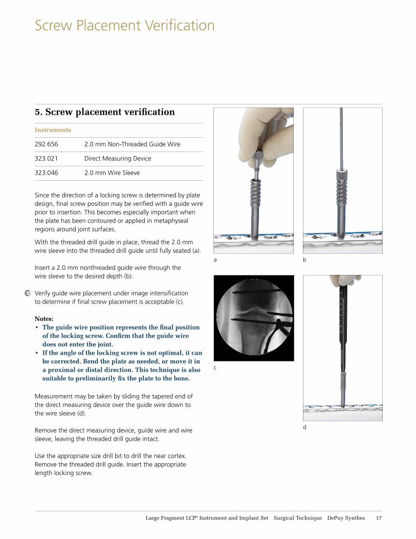
5. Screw placement verification
Instruments
292.656 2.0 mm Non-Threaded Guide Wire
323.021 Direct Measuring Device
323.046 2.0 mm Wire Sleeve
Since the direction of a locking screw is determined by plate design, final screw position may be verified with a guide wire prior to insertion. This becomes especially important when the plate has been contoured or applied in metaphyseal regions around joint surfaces.
With the threaded drill guide in place, thread the 2.0 mm wire sleeve into the threaded drill guide until fully seated (a). Insert a 2.0 mm nonthreaded guide wire through the wire sleeve to the desired depth (b).
Verify guide wire placement under image intensification to determine if final screw placement is acceptable (c).
Notes: • The guide wire position represents the final position
of the locking screw. Confirm that the guide wire does not enter the joint.
• If the angle of the locking screw is not optimal, it can be corrected. Bend the plate as needed, or move it in a proximal or distal direction. This technique is also suitable to preliminarily fix the plate to the bone.
Measurement may be taken by sliding the tapered end of the direct measuring device over the guide wire down to the wire sleeve (d).
Remove the direct measuring device, guide wire and wire sleeve, leaving the threaded drill guide intact.
Use the appropriate size drill bit to drill the near cortex. Remove the threaded drill guide. Insert the appropriate length locking screw.
b
d
18 DePuy Synthes Large Fragment LCP® Instrument and Implant Set Surgical Technique
Postoperative Treatment and Implant Removal
Postoperative treatment
Postoperative treatment with locking compression plates does not differ from conventional internal fixation procedures.
Implant removal
To remove locking screws, unlock all screws from the plate; then remove the screws completely from the bone. This prevents simultaneous rotation of the plate when removing the last locking screw.
Large Fragment LCP® Instrument and Implant Set Surgical Technique DePuy Synthes 19
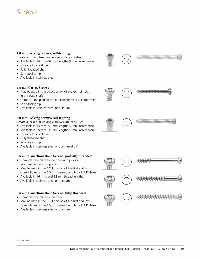
Screws
**Ti-6Al-7Nb.
5.0 mm Locking Screws, self-tappingCreate a locked, fixed-angle screw/plate construct• Available in 14 mm–50 mm lengths (2 mm increments)• Available in 55 mm–90 mm lengths (5 mm increments)• Threaded conical head• Fully threaded shaft• Self-tapping tip• Available in stainless steel or titanium alloy**
4.0 mm Locking Screws, self-tappingCreate a locked, fixed-angle screw/plate construct• Available in 14 mm–62 mm lengths (2 mm increments)• Threaded conical head• Fully threaded shaft• Self-tapping tip• Available in stainless steel
4.5 mm Cortex Screws• May be used in the DCU portion of the Combi holes
in the plate shaft• Compress the plate to the bone or create axial compression• Self-tapping tip• Available in stainless steel or titanium
6.5 mm Cancellous Bone Screws, partially threaded• Compress the plate to the bone and provide
interfragmentary compression• May be used in the DCU portion of the first and last
Combi holes of the 4.5 mm narrow and broad LCP Plates• Available in 16 mm, and 32 mm thread lengths• Available in stainless steel or titanium
6.5 mm Cancellous Bone Screws, fully threaded• Compress the plate to the bone • May be used in the DCU portion of the first and last
Combi holes of the 4.5 mm narrow and broad LCP Plates• Available in stainless steel or titanium
21 DePuy Synthes Large Fragment LCP® Instrument and Implant Set Surgical Technique
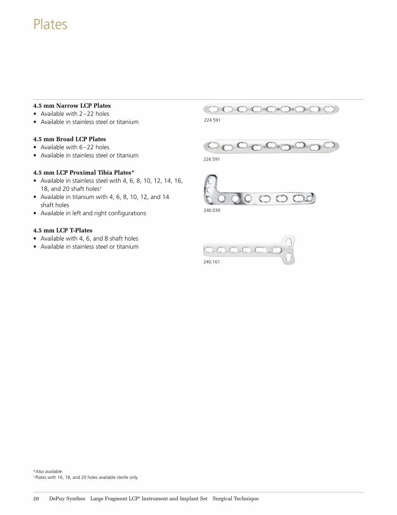
Plates
4.5 mm Narrow LCP Plates• Available with 2–22 holes• Available in stainless steel or titanium
4.5 mm Broad LCP Plates• Available with 6–22 holes• Available in stainless steel or titanium
4.5 mm LCP Proximal Tibia Plates*• Available in stainless steel with 4, 6, 8, 10, 12, 14, 16,
18, and 20 shaft holes†
• Available in titanium with 4, 6, 8, 10, 12, and 14 shaft holes
• Available in left and right configurations
4.5 mm LCP T-Plates• Available with 4, 6, and 8 shaft holes• Available in stainless steel or titanium
224.591
240.161
226.591
240.039
*Also available. †Plates with 16, 18, and 20 holes available sterile only.
Large Fragment LCP® Instrument and Implant Set Surgical Technique DePuy Synthes 21
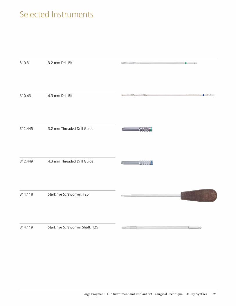
Selected Instruments
310.31 3.2 mm Drill Bit
310.431 4.3 mm Drill Bit
312.445 3.2 mm Threaded Drill Guide
312.449 4.3 mm Threaded Drill Guide
314.118 StarDrive Screwdriver, T25
314.119 StarDrive Screwdriver Shaft, T25
22 DePuy Synthes Large Fragment LCP® Instrument and Implant Set Surgical Technique
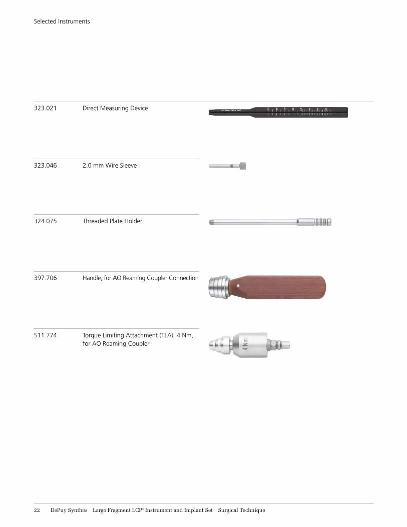
Selected Instruments
323.021 Direct Measuring Device
323.046 2.0 mm Wire Sleeve
324.075 Threaded Plate Holder
397.706 Handle, for AO Reaming Coupler Connection
511.774 Torque Limiting Attachment (TLA), 4 Nm, for AO Reaming Coupler
Large Fragment LCP® Instrument and Implant Set Surgical Technique DePuy Synthes 23
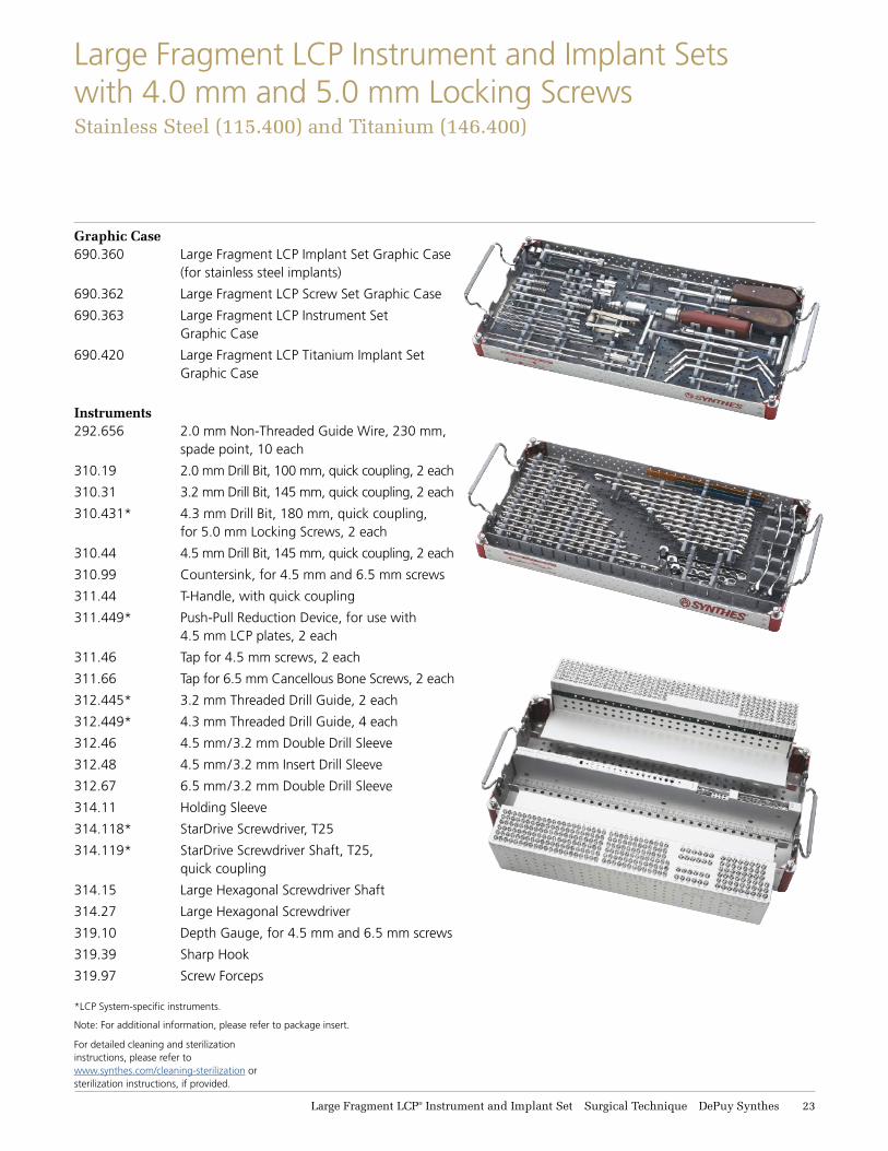
Large Fragment LCP Instrument and Implant Sets with 4.0 mm and 5.0 mm Locking ScrewsStainless Steel (115.411) and Titanium (146.411)
*LCP System-specific instruments.
Graphic Case690.360 Large Fragment LCP Implant Set Graphic Case
(for stainless steel implants)
690.362 Large Fragment LCP Screw Set Graphic Case
690.363 Large Fragment LCP Instrument Set Graphic Case
690.420 Large Fragment LCP Titanium Implant Set Graphic Case
Instruments292.656 2.0 mm Non-Threaded Guide Wire, 230 mm,
spade point, 10 each
310.19 2.0 mm Drill Bit, 100 mm, quick coupling, 2 each
310.31 3.2 mm Drill Bit, 145 mm, quick coupling, 2 each
310.431* 4.3 mm Drill Bit, 180 mm, quick coupling, for 5.0 mm Locking Screws, 2 each
310.44 4.5 mm Drill Bit, 145 mm, quick coupling, 2 each
310.99 Countersink, for 4.5 mm and 6.5 mm screws
311.44 T-Handle, with quick coupling
311.449* Push-Pull Reduction Device, for use with 4.5 mm LCP plates, 2 each
311.46 Tap for 4.5 mm screws, 2 each
311.66 Tap for 6.5 mm Cancellous Bone Screws, 2 each
312.445* 3.2 mm Threaded Drill Guide, 2 each
312.449* 4.3 mm Threaded Drill Guide, 4 each
312.46 4.5 mm/3.2 mm Double Drill Sleeve
312.48 4.5 mm/3.2 mm Insert Drill Sleeve
312.67 6.5 mm/3.2 mm Double Drill Sleeve
314.11 Holding Sleeve
314.118* StarDrive Screwdriver, T25
314.119* StarDrive Screwdriver Shaft, T25, quick coupling
314.15 Large Hexagonal Screwdriver Shaft
314.27 Large Hexagonal Screwdriver
319.10 Depth Gauge, for 4.5 mm and 6.5 mm screws
319.39 Sharp Hook
319.97 Screw Forceps
Note: For additional information, please refer to package insert.
For detailed cleaning and sterilizationinstructions, please refer towww.synthes.com/cleaning-sterilization orsterilization instructions, if provided.
24 DePuy Synthes Large Fragment LCP® Instrument and Implant Set Surgical Technique
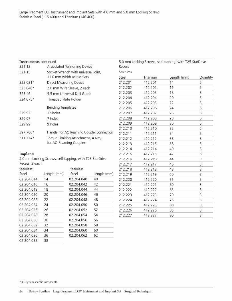
Large Fragment LCP Instrument and Implant Sets with 4.0 mm and 5.0 mm Locking Screws Stainless Steel (115.400) and Titanium (146.400)
Instruments continued321.12 Articulated Tensioning Device
321.15 Socket Wrench with universal joint, 11.0 mm width across flats
323.021* Direct Measuring Device
323.046* 2.0 mm Wire Sleeve, 2 each
323.46 4.5 mm Universal Drill Guide
324.075* Threaded Plate Holder
Bending Templates
329.92 12 holes
329.97 7 holes
329.99 9 holes
397.706* Handle, for AO Reaming Coupler connection
511.774* Torque Limiting Attachment, 4 Nm, for AO Reaming Coupler
Implants4.0 mm Locking Screws, self-tapping, with T25 StarDrive Recess, 3 each
Stainless Stainless Steel Length (mm) Steel Length (mm)
02.204.014 14 02.204.016 16 02.204.018 18 02.204.020 20 02.204.022 22 02.204.024 24 02.204.026 26 02.204.028 28 02.204.030 30 02.204.032 32 02.204.034 34 02.204.036 36 02.204.038 38
*LCP System-specific instruments.
5.0 mm Locking Screws, self-tapping, with T25 StarDrive Recess
Stainless
Steel Titanium Length (mm) Quantity212.201 412.201 14 5212.202 412.202 16 5212.203 412.203 18 5212.204 412.204 20 5212.205 412.205 22 5212.206 412.206 24 5212.207 412.207 26 5212.208 412.208 28 5212.209 412.209 30 5212.210 412.210 32 5212.211 412.211 34 5212.212 412.212 36 5212.213 412.213 38 5212.214 412.214 40 5212.215 412.215 42 5212.216 412.216 44 3212.217 412.217 46 3212.218 412.218 48 3212.219 412.219 50 3212.220 412.220 55 3212.221 412.221 60 3212.222 412.222 65 3212.223 412.223 70 3212.224 412.224 75 3212.225 412.225 80 3212.226 412.226 85 3212.227 412.227 90 3
02.204.040 4002.204.042 4202.204.044 4402.204.046 4602.204.048 4802.204.050 5002.204.052 5202.204.054 5402.204.056 5602.204.058 5802.204.060 6002.204.062 62
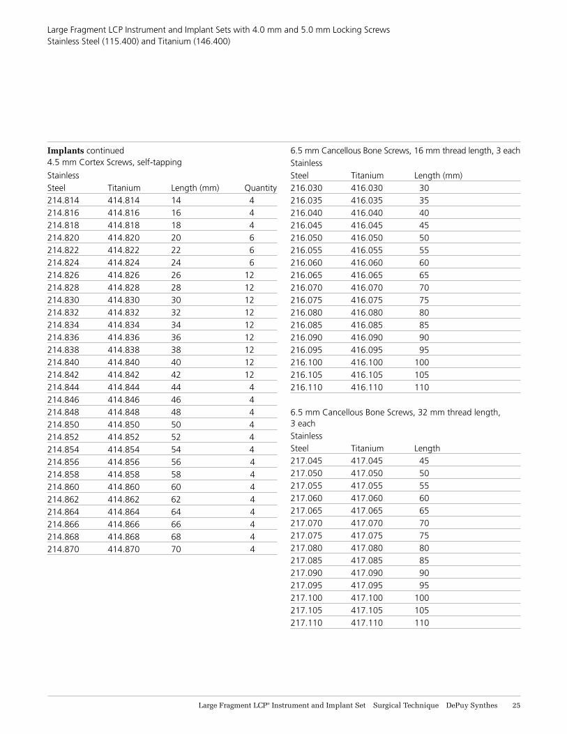
Large Fragment LCP® Instrument and Implant Set Surgical Technique DePuy Synthes 25
Large Fragment LCP Instrument and Implant Sets with 4.0 mm and 5.0 mm Locking Screws Stainless Steel (115.400) and Titanium (146.400)
Implants continued4.5 mm Cortex Screws, self-tapping
Stainless Steel Titanium Length (mm) Quantity214.814 414.814 14 4214.816 414.816 16 4214.818 414.818 18 4214.820 414.820 20 6214.822 414.822 22 6214.824 414.824 24 6214.826 414.826 26 12214.828 414.828 28 12214.830 414.830 30 12214.832 414.832 32 12214.834 414.834 34 12214.836 414.836 36 12214.838 414.838 38 12214.840 414.840 40 12214.842 414.842 42 12214.844 414.844 44 4214.846 414.846 46 4214.848 414.848 48 4214.850 414.850 50 4214.852 414.852 52 4214.854 414.854 54 4214.856 414.856 56 4214.858 414.858 58 4214.860 414.860 60 4214.862 414.862 62 4214.864 414.864 64 4214.866 414.866 66 4214.868 414.868 68 4214.870 414.870 70 4
6.5 mm Cancellous Bone Screws, 16 mm thread length, 3 eachStainless Steel Titanium Length (mm)216.030 416.030 30 216.035 416.035 35 216.040 416.040 40 216.045 416.045 45 216.050 416.050 50 216.055 416.055 55 216.060 416.060 60 216.065 416.065 65 216.070 416.070 70 216.075 416.075 75 216.080 416.080 80 216.085 416.085 85 216.090 416.090 90 216.095 416.095 95 216.100 416.100 100 216.105 416.105 105 216.110 416.110 110
6.5 mm Cancellous Bone Screws, 32 mm thread length, 3 each Stainless Steel Titanium Length 217.045 417.045 45 217.050 417.050 50 217.055 417.055 55 217.060 417.060 60 217.065 417.065 65 217.070 417.070 70 217.075 417.075 75 217.080 417.080 80 217.085 417.085 85 217.090 417.090 90 217.095 417.095 95 217.100 417.100 100 217.105 417.105 105 217.110 417.110 110
26 DePuy Synthes Large Fragment LCP® Instrument and Implant Set Surgical Technique
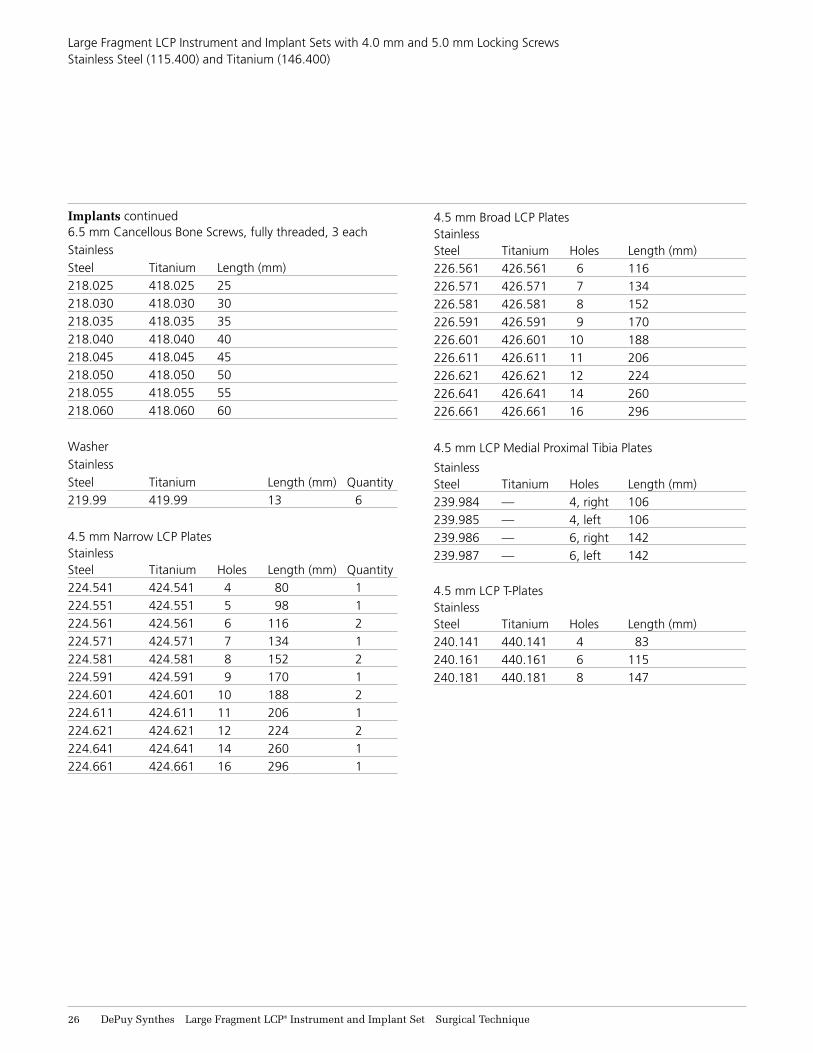
Large Fragment LCP Instrument and Implant Sets with 4.0 mm and 5.0 mm Locking Screws Stainless Steel (115.400) and Titanium (146.400)
Implants continued6.5 mm Cancellous Bone Screws, fully threaded, 3 each Stainless Steel Titanium Length (mm) 218.025 418.025 25 218.030 418.030 30 218.035 418.035 35 218.040 418.040 40 218.045 418.045 45 218.050 418.050 50 218.055 418.055 55 218.060 418.060 60 Washer Stainless Steel Titanium Length (mm) Quantity219.99 419.99 13 6
4.5 mm Narrow LCP PlatesStainless Steel Titanium Holes Length (mm) Quantity224.541 424.541 4 80 1224.551 424.551 5 98 1224.561 424.561 6 116 2224.571 424.571 7 134 1224.581 424.581 8 152 2224.591 424.591 9 170 1224.601 424.601 10 188 2224.611 424.611 11 206 1224.621 424.621 12 224 2224.641 424.641 14 260 1224.661 424.661 16 296 1
4.5 mm Broad LCP PlatesStainless Steel Titanium Holes Length (mm) 226.561 426.561 6 116 226.571 426.571 7 134 226.581 426.581 8 152 226.591 426.591 9 170 226.601 426.601 10 188 226.611 426.611 11 206 226.621 426.621 12 224 226.641 426.641 14 260 226.661 426.661 16 296
4.5 mm LCP Medial Proximal Tibia Plates
Stainless Steel Titanium Holes Length (mm) 239.984 — 4, right 106 239.985 — 4, left 106 239.986 — 6, right 142 239.987 — 6, left 142
4.5 mm LCP T-PlatesStainless Steel Titanium Holes Length (mm) 240.141 440.141 4 83 240.161 440.161 6 115 240.181 440.181 8 147
Large Fragment LCP® Instrument and Implant Set Surgical Technique DePuy Synthes 27
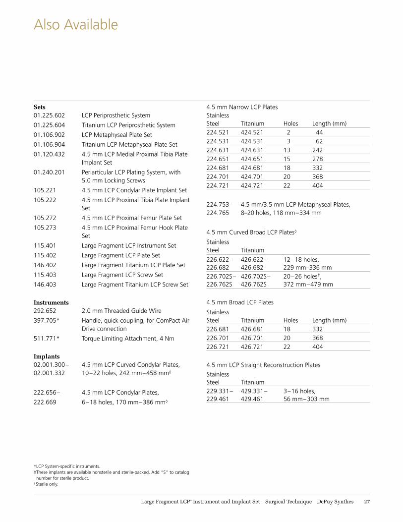
Also Available
Sets01.225.602 LCP Periprosthetic System
01.225.604 Titanium LCP Periprosthetic System
01.106.902 LCP Metaphyseal Plate Set
01.106.904 Titanium LCP Metaphyseal Plate Set
01.120.432 4.5 mm LCP Medial Proximal Tibia Plate Implant Set
01.240.201 Periarticular LCP Plating System, with 5.0 mm Locking Screws
105.221 4.5 mm LCP Condylar Plate Implant Set
105.222 4.5 mm LCP Proximal Tibia Plate Implant Set
105.272 4.5 mm LCP Proximal Femur Plate Set
105.273 4.5 mm LCP Proximal Femur Hook Plate Set
115.401 Large Fragment LCP Instrument Set
115.402 Large Fragment LCP Plate Set
146.402 Large Fragment Titanium LCP Plate Set
115.403 Large Fragment LCP Screw Set
146.403 Large Fragment Titanium LCP Screw Set
Instruments292.652 2.0 mm Threaded Guide Wire
397.705* Handle, quick coupling, for ComPact Air Drive connection
511.771* Torque Limiting Attachment, 4 Nm
Implants02.001.300– 4.5 mm LCP Curved Condylar Plates, 02.001.332 10–22 holes, 242 mm–458 mm◊
222.656– 4.5 mm LCP Condylar Plates,
222.669 6–18 holes, 170 mm–386 mm◊
4.5 mm Narrow LCP PlatesStainless Steel Titanium Holes Length (mm)224.521 424.521 2 44224.531 424.531 3 62224.631 424.631 13 242224.651 424.651 15 278224.681 424.681 18 332224.701 424.701 20 368224.721 424.721 22 404
224.753– 4.5 mm/3.5 mm LCP Metaphyseal Plates, 224.765 8–20 holes, 118 mm–334 mm
4.5 mm Curved Broad LCP Plates◊
Stainless Steel Titanium
226.622– 426.622– 12–18 holes, 226.682 426.682 229 mm–336 mm226.702S– 426.702S– 20–26 holes†, 226.762S 426.762S 372 mm–479 mm
4.5 mm Broad LCP Plates
Stainless Steel Titanium Holes Length (mm)226.681 426.681 18 332226.701 426.701 20 368226.721 426.721 22 404
4.5 mm LCP Straight Reconstruction Plates
Stainless Steel Titanium 229.331– 429.331– 3–16 holes, 229.461 429.461 56 mm–303 mm
*LCP System-specific instruments.◊ These implants are available nonsterile and sterile-packed. Add “S” to catalog
number for sterile product.†Sterile only.
28 DePuy Synthes Large Fragment LCP® Instrument and Implant Set Surgical Technique
Also Available
◊ These implants are available nonsterile and sterile-packed. Add “S” to catalog number for sterile product.
† Sterile only.
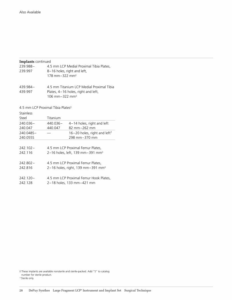
Implants continued239.988– 4.5 mm LCP Medial Proximal Tibia Plates, 239.997 8–16 holes, right and left,
178 mm–322 mm◊
439.984– 4.5 mm Titanium LCP Medial Proximal Tibia 439.997 Plates, 4–16 holes, right and left, 106 mm–322 mm◊
4.5 mm LCP Proximal Tibia Plates◊
Stainless Steel Titanium
240.036– 440.036– 4–14 holes, right and left 240.047 440.047 82 mm–262 mm240.048S– — 16–20 holes, right and left† 240.055S 298 mm–370 mm
242.102– 4.5 mm LCP Proximal Femur Plates, 242.116 2–16 holes, left, 139 mm–391 mm◊
242.802– 4.5 mm LCP Proximal Femur Plates, 242.816 2–16 holes, right, 139 mm–391 mm◊
242.120– 4.5 mm LCP Proximal Femur Hook Plates, 242.128 2–18 holes, 133 mm–421 mm
Discontinued Product
Large Fragment LCP® Instrument and Implant Set Surgical Technique DePuy Synthes 29
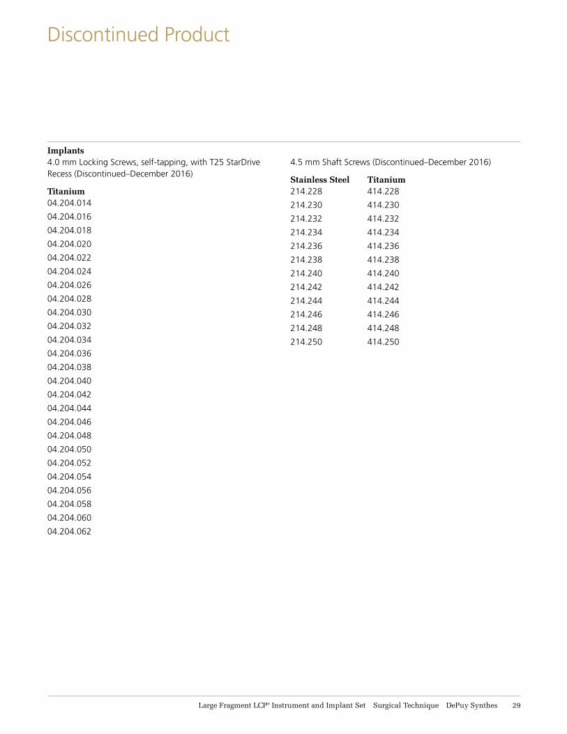
Implants4.0 mm Locking Screws, self-tapping, with T25 StarDrive Recess (Discontinued–December 2016)
Titanium04.204.014
04.204.016
04.204.018
04.204.020
04.204.022
04.204.024
04.204.026
04.204.028
04.204.030
04.204.032
04.204.034
04.204.036
04.204.038
04.204.040
04.204.042
04.204.044
04.204.046
04.204.048
04.204.050
04.204.052
04.204.054
04.204.056
04.204.058
04.204.060
04.204.062
4.5 mm Shaft Screws (Discontinued–December 2016)
Stainless Steel Titanium 214.228 414.228
214.230 414.230
214.232 414.232
214.234 414.234
214.236 414.236
214.238 414.238
214.240 414.240
214.242 414.242
214.244 414.244
214.246 414.246
214.248 414.248
214.250 414.250
Limited Warranty and Disclaimer: DePuy Synthes products are sold with a limited warranty to the original purchaser against defects in workmanship and materials. Any other express or implied warranties, including warranties of merchantability or fitness, are hereby disclaimed.
Please also refer to the package insert(s) or other labeling associated with the devices identified in this surgical technique for additional information.
CAUTION: Federal Law restricts these devices to sale by or on the order of a physician.
Some devices listed in this surgical technique may not have been licensed in accordance with Canadian law and may not be for sale in Canada. Please contact your sales consultant for items approved for sale in Canada.
Not all products may currently be available in all markets.
© DePuy Synthes 2003–2017. All rights reserved.DSUS/TRM/0916/1038(1) 11/17 DV
Synthes USA, LLC 1101 Synthes AvenueMonument, CO 80132
Manufactured or distributed by:Synthes USA Products, LLC 1302 Wrights Lane EastWest Chester, PA 19380
To order (USA): 800-523-0322 To order (Canada): 855-946-8999
Note: For recognized manufacturer, refer to the product label.
www.depuysynthes.com


![Part of the DePuy Synthes Periarticular LCP Plating System ...synthes.vo.llnwd.net/o16/LLNWMB8/US Mobile/Synthes North...14 15 16 4.5 mm LCP Proximal Femur Plates [242. 8XX series]](https://img.pdfslide.net/doc/110x75/6057c8c9cb8d8e38ea604aa1/part-of-the-depuy-synthes-periarticular-lcp-plating-system-mobilesynthes-north.jpg)