Embed Size (px)
Citation preview

Separating walls for Class 1a buildings Timber framed
PARTIWALL®
USGBoral.com Interior Linings Ceilings Cornice Finishes Systems Solutions
Systems Solutions
GENERAL 1
Preface 1
Introduction 1
Description 1
Features and Benefits 1
Design Options 1
Partiwall® Design Concept 2
Partiwall® Construction Sequence 3
DESIGN CONSIDERATIONS 4
Fire Resistance 4
Acoustics 4
Structural 5
MATERIALS 6
SHAFTLINER™ Fire Barrier 6
Occupancy Linings 6
PARTIWALL® SYSTEMS 7
PWT60.1 7
PWT90.1 8
INSTALLATION OF SHAFTLINER™ FIRE BARRIER 9
Set Out and Fixing 9
Protection from Weather 9
Dos and Don'ts 9
Installation Procedure 10
INSTALLATION DETAILS 12
TABLE OF CONTENTS
Cover photo courtesy of Metricon Homes
PrefaceUSG Boral is a plasterboard and ceilings Joint Venture between USG Corporation and Boral Limited, and is one of the leading players in this field.
Operating throughout Asia, Australasia and in the Middle East, USG Boral combines USG’s innovative building products technologies with Boral’s extensive plasterboard manufacturing and distribution footprint in Asia and Australasia.
In Australia USG Boral operates plasterboard manufacturing plants in Queensland, New South Wales and Victoria; a specialty plasters and jointing compounds plant in Victoria and cornice plants in New South Wales and Victoria. The company's products are supplied through a nation-wide distribution network of around 100 company-owned stores and specialised resellers as well as hundreds of hardware stores.
For more information on USG Boral refer to usgboral.com
IntroductionThe Pioneering system of its kind in Australia, USG Boral Partiwall® has become one of the most widely used separating wall systems in attached villa units and townhouse construction.
Excellent acoustic performance, ease of construction and design flexibility makes Partiwall a system of choice on projects ranging from side-by-side duplexes to multi-unit developments.
Partiwall separating wall system is suitable for attached dwellings Class 1a and for top storeys of Class 2 and 3 buildings (subject to Certifier's approval). Contact USG Boral TecASSIST™ for advice.
For multi-residential buildings Class 2, 3 and 9C USG Boral recommends Multiframe™ timber framed construction system (subject to NCC limitations) or IntRwall® separating wall system.
DescriptionPartiwall is essentially a twin stud wall system, which incorporates a single or double layer 25mm SHAFTLINER™ plasterboard fire barrier within the wall cavity.
Partiwall was developed to suit the normal pattern of framed construction and follow-up trades. SHAFTLINER panels are held in position by lightweight steel H- or I-section studs attached to timber or steel framing on both sides with
aluminium clips. Installation of SHAFTLINER fire barrier is carried out during the framing stage and does not require plasterboard screw fixing, jointing or finishing. The internal wall linings are installed at the plastering stage using conventional installation methods as outlined in the USG Boral Plasterboard Installation Manual.
Note: This manual covers timber framed Partiwall systems only. For details of steel framed Partiwall system refer to USG Boral Steel Framed Partiwall brochure.
Features and Benefits• No wet trades are required.
• Panelised construction of SHAFTLINER fire barrier permits easy installation at framing stage – no additional trades are required.
• Permits easy inclusion of services and penetrations, such as switches, power points, light fittings and pipes within the wall.
• Internal wall linings are installed at the plastering stage as per normal construction sequence.
Design OptionsUSG Boral Partiwall has been tested and certified to meet Fire Resistance Levels (FRL) of 60/60/60 and 90/90/90 and acoustic performance equal to or exceeding RW + Ctr = 50 as required by the National Construction Code (NCC).
Partiwall systems are available in three basic types:
Table 1: Partiwall system types
System Type Fire Barrier FRL
PWT60.1 1x25mm SHAFTLINER 60/60/60
PWT90.1 1x25mm SHAFTLINER + 1x16mm FIRESTOP
90/90/90
PWT90.2^ 2x25mm SHAFTLINER 90/90/90
^ System PWT90.2 is not covered in this manual. For acoustic performance refer to USG Boral Systems+. For construction details contact TecASSIST.
All system types are available with a wide range of outer linings, including water and impact resistant linings on one or both sides of the wall.
Construction details are provided for aligned and offset floor configurations, internal-to-external wall transitions and various roof types.
All construction details contained in this manual have been certified by Exova.
GENERAL
1
Partiwall®
GENERAL
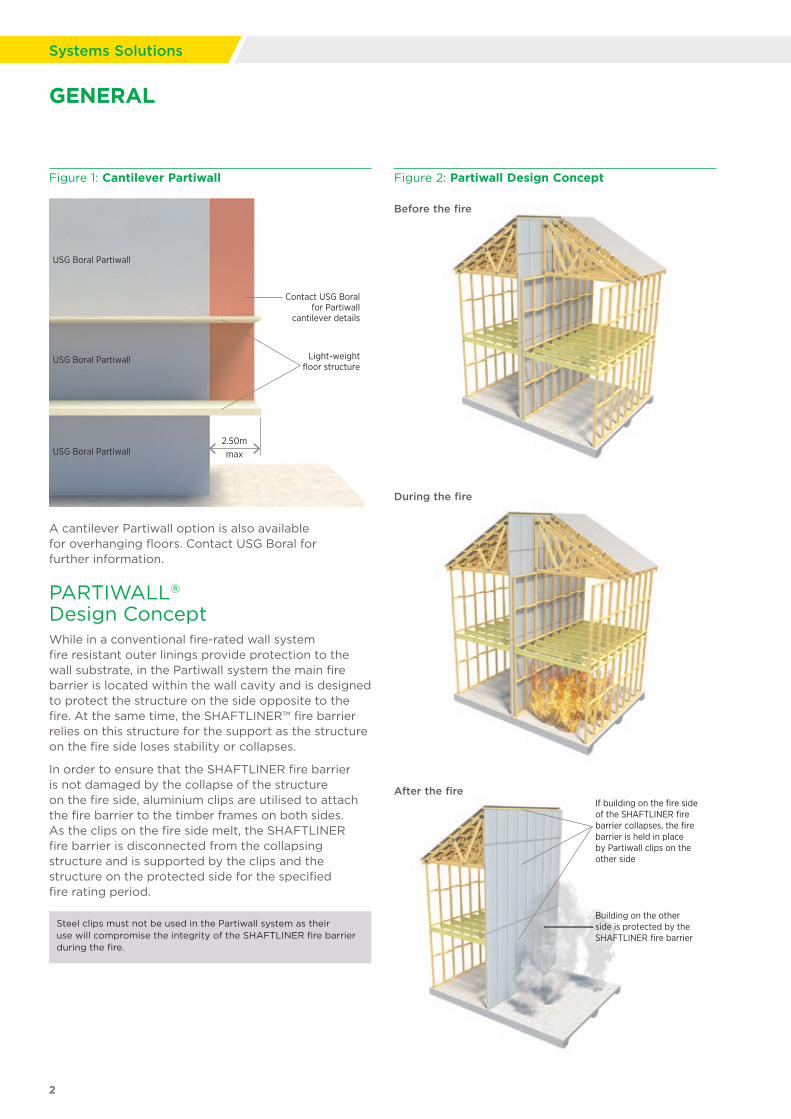
Figure 1: Cantilever Partiwall
Contact USG Boral for Partiwall
cantilever details
Note:USG Boral Partiwall is only suitable for
areas where the fire barrier is continuous from
foundation level to roof level
Light-weight floor structure
USG Boral Partiwall
USG Boral Partiwall
2.50mmaxUSG Boral Partiwall
A cantilever Partiwall option is also available for overhanging floors. Contact USG Boral for further information.
PARTIWALL® Design ConceptWhile in a conventional fire-rated wall system fire resistant outer linings provide protection to the wall substrate, in the Partiwall system the main fire barrier is located within the wall cavity and is designed to protect the structure on the side opposite to the fire. At the same time, the SHAFTLINER™ fire barrier relies on this structure for the support as the structure on the fire side loses stability or collapses.
In order to ensure that the SHAFTLINER fire barrier is not damaged by the collapse of the structure on the fire side, aluminium clips are utilised to attach the fire barrier to the timber frames on both sides. As the clips on the fire side melt, the SHAFTLINER fire barrier is disconnected from the collapsing structure and is supported by the clips and the structure on the protected side for the specified fire rating period.
Steel clips must not be used in the Partiwall system as their use will compromise the integrity of the SHAFTLINER fire barrier during the fire.
Building on the other side is protected by the SHAFTLINER fire barrier
If building on the fire side of the SHAFTLINER fire barrier collapses, the fire barrier is held in place by Partiwall clips on the other side
2
Systems Solutions
Figure 2: Partiwall Design Concept
After the fire
During the fire
Before the fire
3
Partiwall®
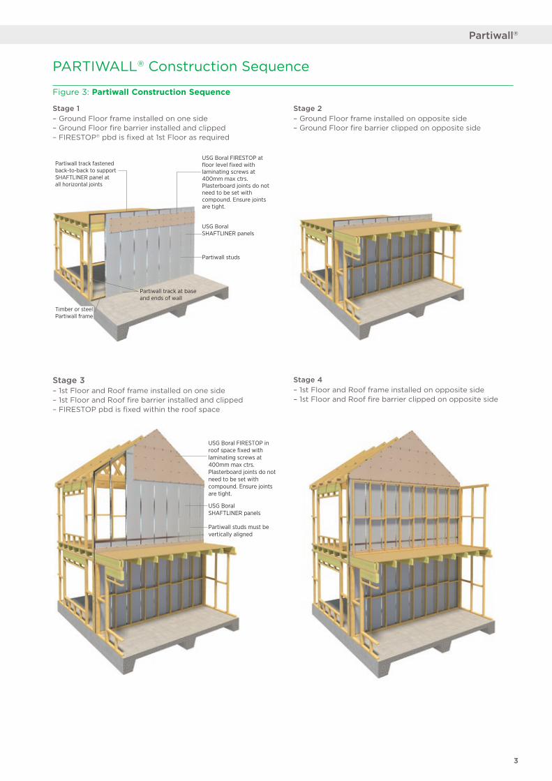
Partiwall track fastened back-to-back to support SHAFTLINER panel at all horizontal joints
Timber or steel Partiwall frame
USG Boral FIRESTOP at floor level fixed with laminating screws at 400mm max ctrs. Plasterboard joints do not need to be set with compound. Ensure joints are tight.
USG Boral SHAFTLINER panels
Partiwall track at base and ends of wall
Partiwall studs
USG Boral FIRESTOP in roof space fixed with laminating screws at 400mm max ctrs. Plasterboard joints do not need to be set with compound. Ensure joints are tight.
USG BoralSHAFTLINER panels
Partiwall studs must be vertically aligned
Figure 3: Partiwall Construction Sequence
Stage 1 – Ground Floor frame installed on one side – Ground Floor fire barrier installed and clipped – FIRESTOP® pbd is fixed at 1st Floor as required
Stage 3 – 1st Floor and Roof frame installed on one side – 1st Floor and Roof fire barrier installed and clipped – FIRESTOP pbd is fixed within the roof space
Stage 4 – 1st Floor and Roof frame installed on opposite side – 1st Floor and Roof fire barrier clipped on opposite side
PARTIWALL® Construction Sequence
Stage 2 – Ground Floor frame installed on opposite side – Ground Floor fire barrier clipped on opposite side
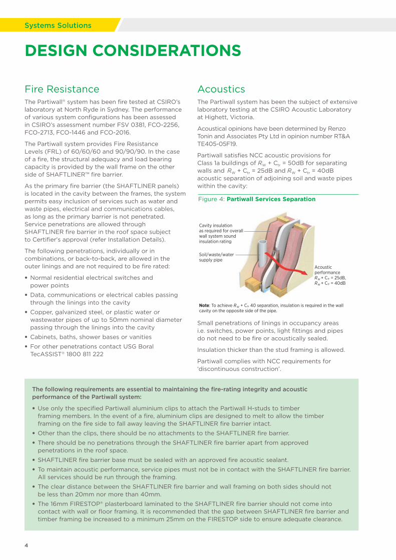
DESIGN CONSIDERATIONS
Fire ResistanceThe Partiwall® system has been fire tested at CSIRO’s laboratory at North Ryde in Sydney. The performance of various system configurations has been assessed in CSIRO’s assessment number FSV 0381, FCO-2256, FCO-2713, FCO-1446 and FCO-2016.
The Partiwall system provides Fire Resistance Levels (FRL) of 60/60/60 and 90/90/90. In the case of a fire, the structural adequacy and load bearing capacity is provided by the wall frame on the other side of SHAFTLINER™ fire barrier.
As the primary fire barrier (the SHAFTLINER panels) is located in the cavity between the frames, the system permits easy inclusion of services such as water and waste pipes, electrical and communications cables, as long as the primary barrier is not penetrated. Service penetrations are allowed through SHAFTLINER fire barrier in the roof space subject to Certifier's approval (refer Installation Details).
The following penetrations, individually or in combinations, or back-to-back, are allowed in the outer linings and are not required to be fire rated:
• Normal residential electrical switches and power points
• Data, communications or electrical cables passing through the linings into the cavity
• Copper, galvanized steel, or plastic water or wastewater pipes of up to 50mm nominal diameter passing through the linings into the cavity
• Cabinets, baths, shower bases or vanities
• For other penetrations contact USG Boral TecASSIST® 1800 811 222
AcousticsThe Partiwall system has been the subject of extensive laboratory testing at the CSIRO Acoustic Laboratory at Highett, Victoria.
Acoustical opinions have been determined by Renzo Tonin and Associates Pty Ltd in opinion number RT&A TE405-05F19.
Partiwall satisfies NCC acoustic provisions for Class 1a buildings of RW + Ctr = 50dB for separating walls and RW + Ctr = 25dB and RW + Ctr = 40dB acoustic separation of adjoining soil and waste pipes within the cavity:
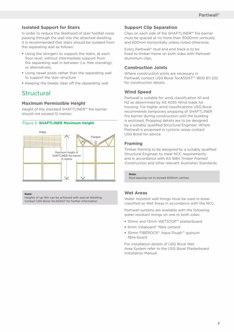
Figure 4: Partiwall Services Separation
Cavity insulation as required for overall wall system sound insulation rating
Soil/waste/water supply pipe
AcousticperformanceRW + Ctr = 25dB,RW + Ctr = 40dB
Note: To achieve RW + Ctr 40 separation, insulation is required in the wall cavity on the opposite side of the pipe.
Small penetrations of linings in occupancy areas i.e. switches, power points, light fittings and pipes do not need to be fire or acoustically sealed.
Insulation thicker than the stud framing is allowed.
Partiwall complies with NCC requirements for ‘discontinuous construction’.
The following requirements are essential to maintaining the fire-rating integrity and acoustic performance of the Partiwall system:
• Use only the specified Partiwall aluminium clips to attach the Partiwall H-studs to timber framing members. In the event of a fire, aluminium clips are designed to melt to allow the timber framing on the fire side to fall away leaving the SHAFTLINER fire barrier intact.
• Other than the clips, there should be no attachments to the SHAFTLINER fire barrier.
• There should be no penetrations through the SHAFTLINER fire barrier apart from approved penetrations in the roof space.
• SHAFTLINER fire barrier base must be sealed with an approved fire acoustic sealant.
• To maintain acoustic performance, service pipes must not be in contact with the SHAFTLINER fire barrier. All services should be run through the framing.
• The clear distance between the SHAFTLINER fire barrier and wall framing on both sides should not be less than 20mm nor more than 40mm.
• The 16mm FIRESTOP® plasterboard laminated to the SHAFTLINER fire barrier should not come into contact with wall or floor framing. It is recommended that the gap between SHAFTLINER fire barrier and timber framing be increased to a minimum 25mm on the FIRESTOP side to ensure adequate clearance.
4
Systems Solutions
Isolated Support for StairsIn order to reduce the likelihood of stair footfall noise passing through the wall into the attached dwelling, it is recommended that stairs should be isolated from the separating wall as follows:
• Using the stringers to support the stairs, at each floor level, without intermediate support from the separating wall in between (i.e. free standing), or alternatively
• Using newel posts rather than the separating wall to support the stair structure
• Keeping the treads clear off the separating wall
Structural
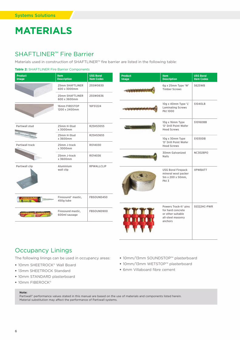
Maximum Permissible HeightHeight of the standard SHAFTLINER™ fire barrier should not exceed 12 metres:
Note: Heights of up 15m can be achieved with special detailing. Contact USG Boral TecASSIST for further information.
Support Clip SeparationClips on each side of the SHAFTLINER™ fire barrier must be spaced at no more than 3000mm vertically and 600mm horizontally unless noted otherwise.
Every Partiwall® stud and end track is to be fixed to timber frame on both sides with Partiwall aluminium clips.
Construction JointsWhere construction joints are necessary in Partiwall, contact USG Boral TecASSIST™ 1800 811 222 for construction details.
Wind SpeedPartiwall is suitable for wind classification N1 and N2 as determined by AS 4055 Wind loads for housing. For higher wind classifications USG Boral recommends temporary propping of SHAFTLINER fire barrier during construction until the building is enclosed. Propping details are to be designed by a suitably qualified Structural Engineer. Where Partiwall is proposed in cyclonic areas contact USG Boral for advice.
FramingTimber framing to be designed by a suitably qualified Structural Engineer to meet NCC requirements, and in accordance with AS 1684 Timber Framed Construction and other relevant Australian Standards.
Wet AreasWater resistant wall linings must be used in areas classified as Wet Areas in accordance with the NCC.
Partiwall systems are available with the following water resistant linings on one or both sides:
• 10mm and 13mm WETSTOP™ plasterboard
• 6mm Villaboard® fibre cement
• 10mm FIBEROCK® Aqua-Tough™ gypsum fibre board
For installation details of USG Boral Wet Area System refer to the USG Boral Plasterboard Installation Manual.
Note: Stud spacing not to exceed 600mm centres.
5
Partiwall®
Ridge
Parapet
Maximum height of SHAFTLINER fire barrier
12 metres
Figure 5: SHAFTLINER Maximum Height
Note: Partiwall® performance values stated in this manual are based on the use of materials and components listed herein. Material substitution may affect the performance of Partiwall systems.
6
Systems Solutions
MATERIALS
Occupancy LiningsThe following linings can be used in occupancy areas:
• 10mm SHEETROCK® Wall Board
• 13mm SHEETROCK Standard
• 10mm STANDARD plasterboard
• 10mm FIBEROCK®
• 10mm/13mm SOUNDSTOP™ plasterboard
• 10mm/13mm WETSTOP™ plasterboard
• 6mm Villaboard fibre cement
Product Image
Item Description
USG Boral Item Codes
25mm SHAFTLINER 600 x 3000mm
25SW0630
25mm SHAFTLINER 600 x 3600mm
25SW0636
16mm FIRESTOP 1200 x 2400mm
16FS1224
Partiwall stud 25mm H-Stud x 3000mm
R25HS3055
25mm H-Stud x 3600mm
R25HS3655
Partiwall track 25mm J-track x 3000mm
RO14030
25mm J-track x 3600mm
RO14036
Partiwall clip Aluminium wall clip
RPWALLCLIP
Firesound® mastic, 450g tube
FBSOUND450
Firesound mastic, 600ml sausage
FBSOUND900
Product Image
Item Description
USG Boral Item Codes
6g x 25mm Type ‘W’ Timber Screws
S625WB
10g x 40mm Type ‘L’ Laminating Screws Pkt 1000
S1040LB
10g x 16mm Type ‘D’ Drill Point Wafer Head Screws
S1016DBB
10g x 30mm Type ‘D’ Drill Point Wafer Head Screws
S1030DB
30mm Galvanized Nails
NC3028PO
USG Boral Firepack mineral wool packer 5m x 200 x 50mm, Pkt 3
IIPWBATT
Powers Track-It® pins for hard concrete or other suitable all-steel masonry anchors
55322HC-PWR
SHAFTLINER™ Fire BarrierMaterials used in construction of SHAFTLINER™ fire barrier are listed in the following table:
Table 2: SHAFTLINER Fire Barrier Components
7
Partiwall®
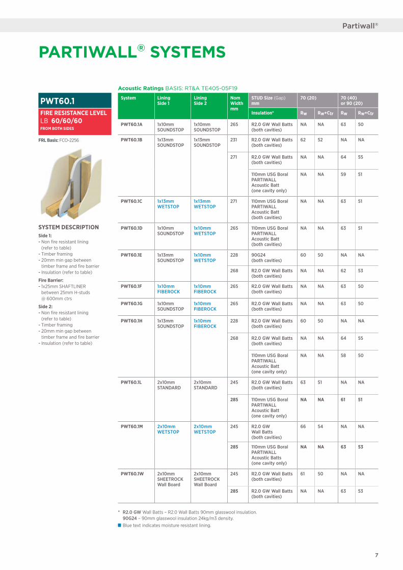
Acoustic Ratings BASIS: RT&A TE405-05F19
System Lining Side 1
Lining Side 2
Nom Width mm
STUD Size (Gap) mm
70 (20) 70 (40) or 90 (20)
Insulation* Rw Rw+Ctr Rw Rw+Ctr
PWT60.1A 1x10mm SOUNDSTOP
1x10mm SOUNDSTOP
265 R2.0 GW Wall Batts (both cavities)
NA NA 63 50
PWT60.1B 1x13mm SOUNDSTOP
1x13mm SOUNDSTOP
231 R2.0 GW Wall Batts (both cavities)
62 52 NA NA
271 R2.0 GW Wall Batts (both cavities)
NA NA 64 55
110mm USG Boral PARTIWALL Acoustic Batt (one cavity only)
NA NA 59 51
PWT60.1C 1x13mm WETSTOP
1x13mm WETSTOP
271 110mm USG Boral PARTIWALL Acoustic Batt (both cavities)
NA NA 63 51
PWT60.1D 1x10mm SOUNDSTOP
1x10mm WETSTOP
265 110mm USG Boral PARTIWALL Acoustic Batt (both cavities)
NA NA 63 51
PWT60.1E 1x13mm SOUNDSTOP
1x10mm WETSTOP
228 90G24 (both cavities)
60 50 NA NA
268 R2.0 GW Wall Batts (both cavities)
NA NA 62 53
PWT60.1F 1x10mm FIBEROCK
1x10mm FIBEROCK
265 R2.0 GW Wall Batts (both cavities)
NA NA 63 50
PWT60.1G 1x10mm SOUNDSTOP
1x10mm FIBEROCK
265 R2.0 GW Wall Batts (both cavities)
NA NA 63 50
PWT60.1H 1x13mm SOUNDSTOP
1x10mm FIBEROCK
228 R2.0 GW Wall Batts (both cavities)
60 50 NA NA
268 R2.0 GW Wall Batts (both cavities)
NA NA 64 55
110mm USG Boral PARTIWALL Acoustic Batt (one cavity only)
NA NA 58 50
PWT60.1L 2x10mm STANDARD
2x10mm STANDARD
245 R2.0 GW Wall Batts (both cavities)
63 51 NA NA
285 110mm USG Boral PARTIWALL Acoustic Batt (one cavity only)
NA NA 61 51
PWT60.1M 2x10mm WETSTOP
2x10mm WETSTOP
245 R2.0 GW Wall Batts (both cavities)
66 54 NA NA
285 110mm USG Boral PARTIWALL Acoustic Batts (one cavity only)
NA NA 63 53
PWT60.1W 2x10mm SHEETROCK Wall Board
2x10mm SHEETROCK Wall Board
245 R2.0 GW Wall Batts (both cavities)
61 50 NA NA
285 R2.0 GW Wall Batts (both cavities)
NA NA 63 53
SYSTEM DESCRIPTIONSide 1: - Non fire resistant lining (refer to table) - Timber framing - 20mm min gap between timber frame and fire barrier - Insulation (refer to table)
Fire Barrier: - 1x25mm SHAFTLINER between 25mm H-studs @ 600mm ctrs
Side 2: - Non fire resistant lining (refer to table) - Timber framing - 20mm min gap between timber frame and fire barrier - Insulation (refer to table)
PWT60.1FIRE RESISTANCE LEVELLB 60/60/60FROM BOTH SIDES
FRL Basis: FCO-2256
PARTIWALL® SYSTEMS
* R2.0 GW Wall Batts – R2.0 Wall Batts 90mm glasswool insulation. 90G24 – 90mm glasswool insulation 24kg/m3 density.
Blue text indicates moisture resistant lining.
8
Systems Solutions
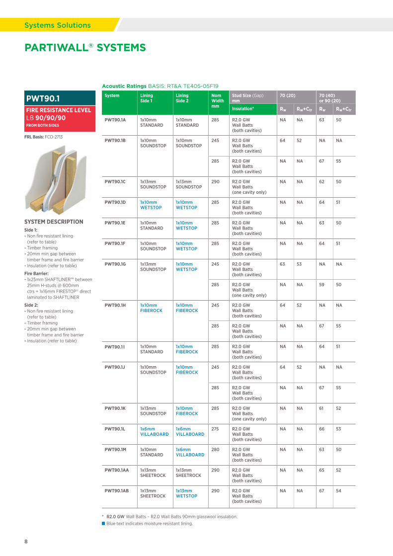
PARTIWALL® SYSTEMS
Acoustic Ratings BASIS: RT&A TE405-05F19
System Lining Side 1
Lining Side 2
Nom Width mm
Stud Size (Gap) mm
70 (20) 70 (40) or 90 (20)
Insulation* Rw Rw+Ctr Rw Rw+Ctr
PWT90.1A 1x10mm STANDARD
1x10mm STANDARD
285 R2.0 GW Wall Batts (both cavities)
NA NA 63 50
PWT90.1B 1x10mm SOUNDSTOP
1x10mm SOUNDSTOP
245 R2.0 GW Wall Batts (both cavities)
64 52 NA NA
285 R2.0 GW Wall Batts (both cavities)
NA NA 67 55
PWT90.1C 1x13mm SOUNDSTOP
1x13mm SOUNDSTOP
290 R2.0 GW Wall Batts (one cavity only)
NA NA 62 50
PWT90.1D 1x10mm WETSTOP
1x10mm WETSTOP
285 R2.0 GW Wall Batts (both cavities)
NA NA 64 51
PWT90.1E 1x10mm STANDARD
1x10mm WETSTOP
285 R2.0 GW Wall Batts (both cavities)
NA NA 63 50
PWT90.1F 1x10mm SOUNDSTOP
1x10mm WETSTOP
285 R2.0 GW Wall Batts (both cavities)
NA NA 64 51
PWT90.1G 1x13mm SOUNDSTOP
1x10mm WETSTOP
245 R2.0 GW Wall Batts (both cavities)
63 53 NA NA
285 R2.0 GW Wall Batts (one cavity only)
NA NA 59 50
PWT90.1H 1x10mm FIBEROCK
1x10mm FIBEROCK
245 R2.0 GW Wall Batts (both cavities)
64 52 NA NA
285 R2.0 GW Wall Batts (both cavities)
NA NA 67 55
PWT90.1I 1x10mm STANDARD
1x10mm FIBEROCK
285 R2.0 GW Wall Batts (both cavities)
NA NA 64 51
PWT90.1J 1x10mm SOUNDSTOP
1x10mm FIBEROCK
245 R2.0 GW Wall Batts (both cavities)
64 52 NA NA
285 R2.0 GW Wall Batts (both cavities)
NA NA 67 55
PWT90.1K 1x13mm SOUNDSTOP
1x10mm FIBEROCK
285 R2.0 GW Wall Batts (one cavity only)
NA NA 61 52
PWT90.1L 1x6mm VILLABOARD
1x6mm VILLABOARD
275 R2.0 GW Wall Batts (both cavities)
NA NA 66 53
PWT90.1M 1x10mm STANDARD
1x6mm VILLABOARD
280 R2.0 GW Wall Batts (both cavities)
NA NA 63 50
PWT90.1AA 1x13mm SHEETROCK
1x13mm SHEETROCK
290 R2.0 GW Wall Batts (both cavities)
NA NA 65 52
PWT90.1AB 1x13mm SHEETROCK
1x13mm WETSTOP
290 R2.0 GW Wall Batts (both cavities)
NA NA 67 54
SYSTEM DESCRIPTIONSide 1: - Non fire resistant lining (refer to table) - Timber framing - 20mm min gap between timber frame and fire barrier - Insulation (refer to table)
Fire Barrier: - 1x25mm SHAFTLINER™ between 25mm H-studs @ 600mm ctrs + 1x16mm FIRESTOP® direct laminated to SHAFTLINER
Side 2: - Non fire resistant lining (refer to table) - Timber framing - 20mm min gap between timber frame and fire barrier - Insulation (refer to table)
PWT90.1FIRE RESISTANCE LEVELLB 90/90/90FROM BOTH SIDES
FRL Basis: FCO-2713
* R2.0 GW Wall Batts – R2.0 Wall Batts 90mm glasswool insulation. Blue text indicates moisture resistant lining.
9
Partiwall®
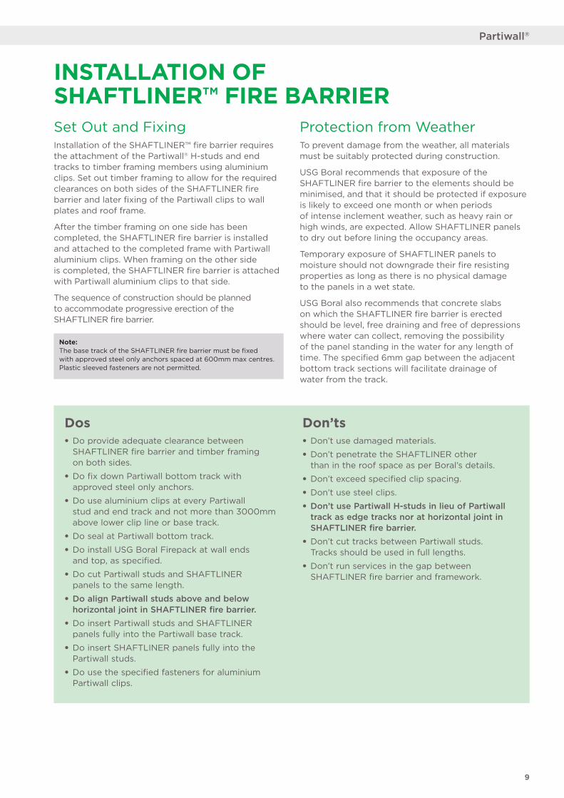
Set Out and FixingInstallation of the SHAFTLINER™ fire barrier requires the attachment of the Partiwall® H-studs and end tracks to timber framing members using aluminium clips. Set out timber framing to allow for the required clearances on both sides of the SHAFTLINER fire barrier and later fixing of the Partiwall clips to wall plates and roof frame.
After the timber framing on one side has been completed, the SHAFTLINER fire barrier is installed and attached to the completed frame with Partiwall aluminium clips. When framing on the other side is completed, the SHAFTLINER fire barrier is attached with Partiwall aluminium clips to that side.
The sequence of construction should be planned to accommodate progressive erection of the SHAFTLINER fire barrier.
Note: The base track of the SHAFTLINER fire barrier must be fixed with approved steel only anchors spaced at 600mm max centres. Plastic sleeved fasteners are not permitted.
Protection from WeatherTo prevent damage from the weather, all materials must be suitably protected during construction.
USG Boral recommends that exposure of the SHAFTLINER fire barrier to the elements should be minimised, and that it should be protected if exposure is likely to exceed one month or when periods of intense inclement weather, such as heavy rain or high winds, are expected. Allow SHAFTLINER panels to dry out before lining the occupancy areas.
Temporary exposure of SHAFTLINER panels to moisture should not downgrade their fire resisting properties as long as there is no physical damage to the panels in a wet state.
USG Boral also recommends that concrete slabs on which the SHAFTLINER fire barrier is erected should be level, free draining and free of depressions where water can collect, removing the possibility of the panel standing in the water for any length of time. The specified 6mm gap between the adjacent bottom track sections will facilitate drainage of water from the track.
INSTALLATION OF SHAFTLINER™ FIRE BARRIER
Dos• Do provide adequate clearance between
SHAFTLINER fire barrier and timber framing on both sides.
• Do fix down Partiwall bottom track with approved steel only anchors.
• Do use aluminium clips at every Partiwall stud and end track and not more than 3000mm above lower clip line or base track.
• Do seal at Partiwall bottom track.
• Do install USG Boral Firepack at wall ends and top, as specified.
• Do cut Partiwall studs and SHAFTLINER panels to the same length.
• Do align Partiwall studs above and below horizontal joint in SHAFTLINER fire barrier.
• Do insert Partiwall studs and SHAFTLINER panels fully into the Partiwall base track.
• Do insert SHAFTLINER panels fully into the Partiwall studs.
• Do use the specified fasteners for aluminium Partiwall clips.
Don’ts• Don’t use damaged materials.
• Don’t penetrate the SHAFTLINER other than in the roof space as per Boral’s details.
• Don’t exceed specified clip spacing.
• Don’t use steel clips.
• Don’t use Partiwall H-studs in lieu of Partiwall track as edge tracks nor at horizontal joint in SHAFTLINER fire barrier.
• Don’t cut tracks between Partiwall studs. Tracks should be used in full lengths.
• Don’t run services in the gap between SHAFTLINER fire barrier and framework.
• Ensure that SHAFTLINER™ panels, Partiwall® studs and end tracks are the same length. Cut to length if required.
• In a multi-level SHAFTLINER fire barrier, Partiwall studs at upper levels must align with the studs below.
• Partiwall aluminium clips must be installed progressively as SHAFTLINER fire barrier is erected.
• Partiwall aluminium clips must be spaced at maximum 600mm horizontally and 3000mm vertically.
• For aligned floors Partiwall aluminium clips must be directly opposite on both sides of the Partiwall studs.
• For offset floors Partiwall aluminium clips can be staggered in line with floors on each side of the wall (refer Figure 7).
• Fix Partiwall aluminium clips to Partiwall studs with 2 x 10g x 16mm Type 'D' drill point wafer head screws (2 x 10g x 30mm Type 'D' drill point wafer head screws if fixing through 16mm FIRESTOP® plasterboard).
• Fix Partiwall aluminium clip to timber frame with 2 x 6g x 25mm Type 'W' timber screws or 2 x 2mm x 30mm galvanised nails.
• SHAFTLINER fire barrier must be adequately braced against wind forces until the building is enclosed.
10
Systems Solutions
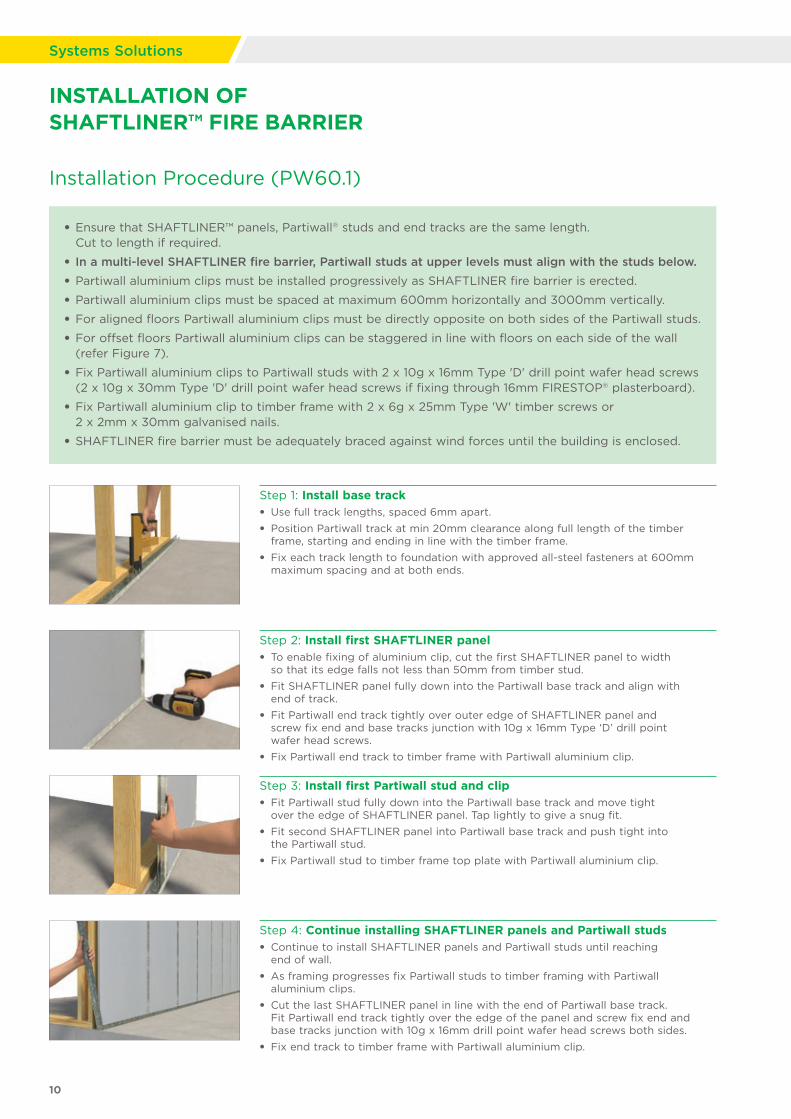
Step 2: Install first SHAFTLINER panel• To enable fixing of aluminium clip, cut the first SHAFTLINER panel to width
so that its edge falls not less than 50mm from timber stud.
• Fit SHAFTLINER panel fully down into the Partiwall base track and align with end of track.
• Fit Partiwall end track tightly over outer edge of SHAFTLINER panel and screw fix end and base tracks junction with 10g x 16mm Type ‘D’ drill point wafer head screws.
• Fix Partiwall end track to timber frame with Partiwall aluminium clip.
Step 4: Continue installing SHAFTLINER panels and Partiwall studs• Continue to install SHAFTLINER panels and Partiwall studs until reaching
end of wall.
• As framing progresses fix Partiwall studs to timber framing with Partiwall aluminium clips.
• Cut the last SHAFTLINER panel in line with the end of Partiwall base track. Fit Partiwall end track tightly over the edge of the panel and screw fix end and base tracks junction with 10g x 16mm drill point wafer head screws both sides.
• Fix end track to timber frame with Partiwall aluminium clip.
Step 3: Install first Partiwall stud and clip• Fit Partiwall stud fully down into the Partiwall base track and move tight
over the edge of SHAFTLINER panel. Tap lightly to give a snug fit.
• Fit second SHAFTLINER panel into Partiwall base track and push tight into the Partiwall stud.
• Fix Partiwall stud to timber frame top plate with Partiwall aluminium clip.
Step 1: Install base track• Use full track lengths, spaced 6mm apart.
• Position Partiwall track at min 20mm clearance along full length of the timber frame, starting and ending in line with the timber frame.
• Fix each track length to foundation with approved all-steel fasteners at 600mm maximum spacing and at both ends.
Installation Procedure (PW60.1)
INSTALLATION OF SHAFTLINER™ FIRE BARRIER
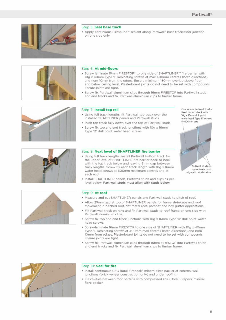
Partiwall studs on upper levels must
align with studs below
Continuous Partiwall tracks fixed back-to-back with 10g x 16mm drill point wafer head Type 'D' screws @ 600mm ctrs
11
Partiwall®
Step 10: Seal for fire• Install continuous USG Boral Firepack® mineral fibre packer at external wall
junctions (brick veneer construction only) and under roofing.
• Fill cavities between roof battens with compressed USG Boral Firepack mineral fibre packer.
Step 9: At roof• Measure and cut SHAFTLINER panels and Partiwall studs to pitch of roof.
• Allow 25mm gap at top of SHAFTLINER panels for frame shrinkage and roof movement in pitched roof, flat metal roof, parapet and box gutter applications.
• Fix Partiwall track on rake and fix Partiwall studs to roof frame on one side with Partiwall aluminium clips.
• Screw fix top and end track junctions with 10g x 16mm Type 'D' drill point wafer head screws.
• Screw-laminate 16mm FIRESTOP to one side of SHAFTLINER with 10g x 40mm Type ‘L’ laminating screws at 400mm max centres (both directions) and nom 10mm from edges. Plasterboard joints do not need to be set with compounds. Ensure joints are tight.
• Screw fix Partiwall aluminium clips through 16mm FIRESTOP into Partiwall studs and end tracks and fix Partiwall aluminium clips to timber frame.
Step 8: Next level of SHAFTLINER fire barrier• Using full track lengths, install Partiwall bottom track for
the upper level of SHAFTLINER fire barrier back-to-back with the top track below and leaving 6mm gap between track lengths. Screw fix each track length with 10g x 16mm wafer head screws at 600mm maximum centres and at each end.
• Install SHAFTLINER panels, Partiwall studs and clips as per level below. Partiwall studs must align with studs below.
Step 6: At mid-floors• Screw laminate 16mm FIRESTOP® to one side of SHAFTLINER™ fire barrier with
10g x 40mm Type ‘L’ laminating screws at max 400mm centres (both directions) and nom 10mm from the edges. Ensure minimum 150mm overlap above floor and below ceiling level. Plasterboard joints do not need to be set with compounds. Ensure joints are tight.
• Screw fix Partiwall aluminium clips through 16mm FIRESTOP into Partiwall studs and end tracks and fix Partiwall aluminium clips to timber frame.
Step 7: Install top rail• Using full track lengths, fit Partiwall top track over the
installed SHAFTLINER panels and Partiwall studs.
• Push top track fully down over the top of Partiwall studs.
• Screw fix top and end track junctions with 10g x 16mm Type ‘D’ drill point wafer head screws.
USG Boral Firestop
USG Boral Shaftliner
USG Boral Firestop
INSERT DETAIL
Step 5: Seal base track• Apply continuous Firesound™ sealant along Partiwall® base track/floor junction
on one side only
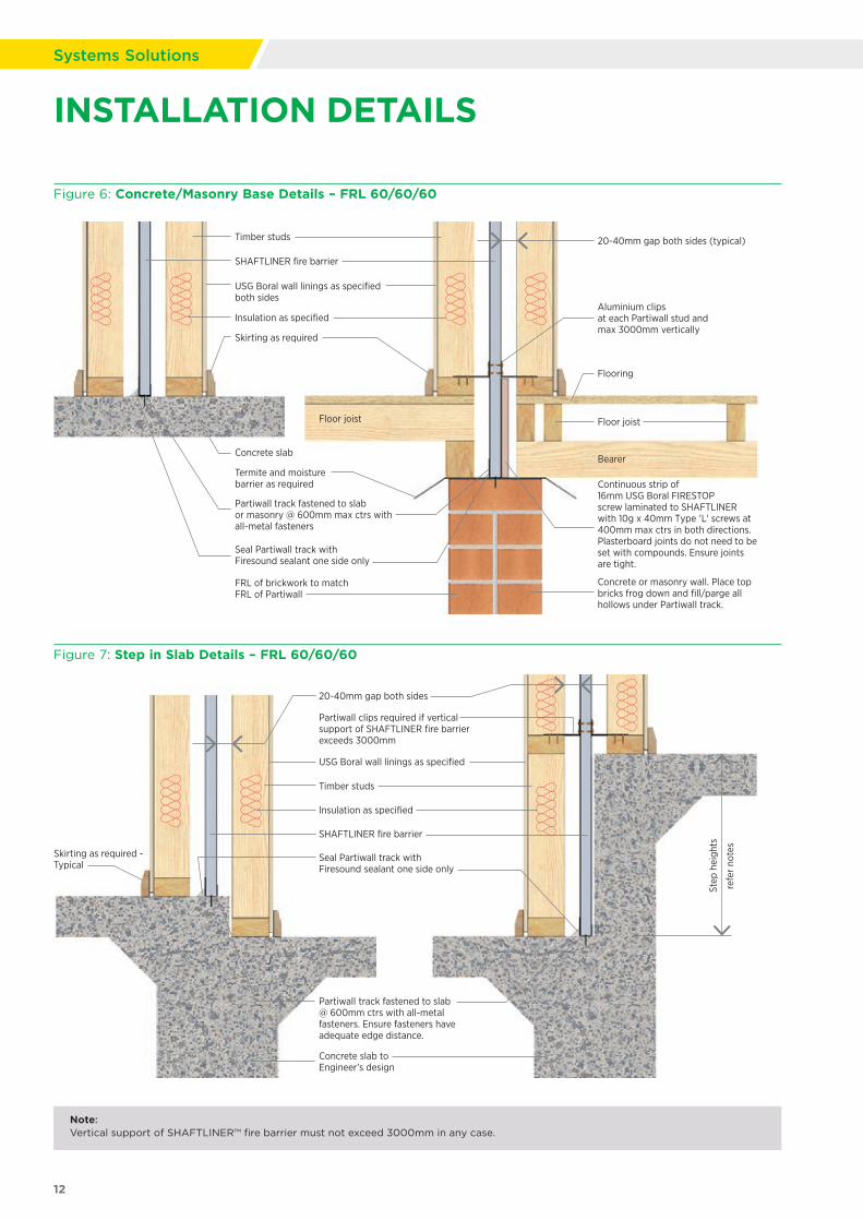
Figure 6: Concrete/Masonry Base Details – FRL 60/60/60
Figure 7: Step in Slab Details – FRL 60/60/60
Note: Vertical support of SHAFTLINER™ fire barrier must not exceed 3000mm in any case.
Step
hei
ghts
20-40mm gap both sides
Concrete slab to Engineer’s design
Skirting as required - Typical
USG Boral wall linings as specified
Timber studs
Insulation as specified
SHAFTLINER fire barrier
Seal Partiwall track with Firesound sealant one side only
Partiwall track fastened to slab @ 600mm ctrs with all-metal fasteners. Ensure fasteners have adequate edge distance.
Partiwall clips required if vertical support of SHAFTLINER fire barrier exceeds 3000mm
refe
r no
tes
Seal Partiwall track with Firesound sealant one side only
20-40mm gap both sides (typical)
Flooring
Floor joist
Termite and moisture barrier as required
FRL of brickwork to match FRL of Partiwall
Floor joist
Bearer
Aluminium clips at each Partiwall stud and max 3000mm vertically
Continuous strip of 16mm USG Boral FIRESTOP screw laminated to SHAFTLINER with 10g x 40mm Type 'L' screws at 400mm max ctrs in both directions. Plasterboard joints do not need to be set with compounds. Ensure joints are tight
Concrete or masonry wall. Place top bricks frog down and fill/parge all hollows under Partiwall track
USG Boral wall linings as specified both sides
Timber studs
Insulation as specified
SHAFTLINER fire barrier
Skirting as required
Concrete slab
Partiwall track fastened to slab or masonry @ 600mm max ctrs with all-metal fasteners
.
.
12
Systems Solutions
INSTALLATION DETAILS
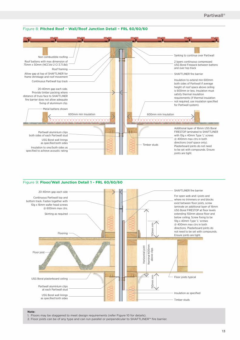
Figure 8: Pitched Roof – Wall/Roof Junction Detail – FRL 60/60/60
600mm min Insulation 600mm min Insulation
SHAFTLINER fire barrier
Timber studs
Non combustible roofing
Roof framing
Roof battens with max dimension of 75mm x 50mm (NCCVol 2 Cl 3.7.1.8d)
Insulation to one/both sides as specified to achieve acoustic rating
Insulation to extend min 600mm both sides of Partiwall if average height of roof space above ceiling is 600mm or less. Insulation must satisfy thermal insulation requirements (if thermal insulation not required, use insulation specified for Partiwall system).
Additional layer of 16mm USG Boral FIRESTOP laminated to SHAFTLINER with 10g x 40mm Type ‘L’ screws @ 400mm max ctrs in both directions (roof space only). Plasterboard joints do not need to be set with compounds. Ensure joints are tight.
2 layers continuous compressed USG Boral Firepack between battens and over top track
Allow gap at top of SHAFTLINER for frame shrinkage and roof movement
Continuous Partiwall top track
20-40mm gap each side. Provide timber packing where
distance of truss face to SHAFTLINER fire barrier does not allow adequate
fixing of aluminium clip.
Partiwall aluminium clips both sides of each Partiwall stud
USG Boral wall linings as specified both sides
Metal battens shown
Sarking to continue over Partiwall
Note: 1. Floors may be staggered to meet design requirements (refer Figure 10 for details). 2. Floor joists can be of any type and can run parallel or perpendicular to SHAFTLINER™ fire barrier.
20-40mm gap each side
Continuous Partiwall top and bottom track. Fasten together with
10g x 16mm wafer head screws @ 600mm max ctrs.
Skirting as required
Flooring
Floor joist
USG Boral plasterboard ceiling
Partiwall aluminium clipsat each Partiwall stud
USG Boral wall liningsas specified both sides
SHAFTLINER fire barrier
For open web and I-joists and where no trimmers or end blocks exist between floor joists, screw laminate an additional layer of 16mm USG Boral FIRESTOP at floor levels extending 150mm above floor and below ceiling. Screw fixing to be 10g x 40mm Type 'L' screws @ 400mm max ctrs in both directions. Plasterboard joints do not need to be set with compounds. Ensure joints are tight.
Floor joists typical
Timber studs
Insulation as specified
Hor
izon
tal j
oint
Nom
inal
60
0m
mab
ove
clip
s15
0m
m m
in15
0m
m m
in
Figure 9: Floor/Wall Junction Detail 1 - FRL 60/60/60
13
Partiwall®
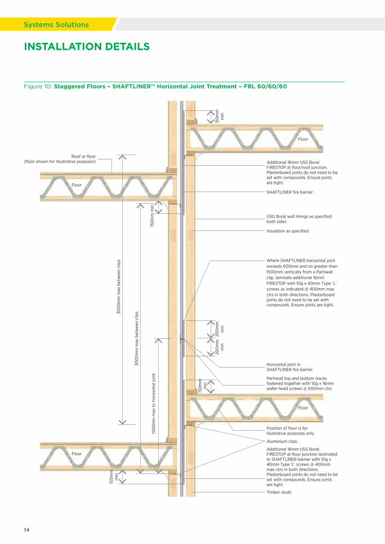
Figure 10: Staggered Floors – SHAFTLINER™ Horizontal Joint Treatment – FRL 60/60/60
Insulation as specified
150
mm
m
in
150
mm
m
in
200
mm
m
in
150
mm
m
in
200
mm
m
in
150
mm
min
Timber studs
Additional 16mm USG Boral FIRESTOP at floor/roof junction.Plasterboard joints do not need to be set with compounds. Ensure joints are tight.
SHAFTLINER fire barrier
USG Boral wall linings as specified both sides
Partiwall top and bottom tracks fastened together with 10g x 16mm wafer head screws @ 600mm ctrs
Aluminium clips
Additional 16mm USG Boral FIRESTOP at floor junction laminated to SHAFTLINER barrier with 10g x 40mm Type ‘L’ screws @ 400mm max ctrs in both directions. Plasterboard joints do not need to be set with compounds. Ensure joints are tight.
Position of floor is for illustrative purposes only
Where SHAFTLINER horizontal joint exceeds 600mm and no greater than 1500mm vertically from a Partiwall clip, laminate additional 16mm FIRESTOP with 10g x 40mm Type 'L' screws as indicated @ 400mm max ctrs in both directions. Plasterboard joints do not need to be set with compounds. Ensure joints are tight.
Horizontal joint in SHAFTLINER fire barrier
300
0m
m m
ax b
etw
een
clip
s
300
0m
m m
ax b
etw
een
clip
s
Roof or floor (floor shown for illustrative purposes)
Floor
Floor
Floor
Floor
150
0m
m m
ax to
hor
izon
tal j
oint
14
Systems Solutions
INSTALLATION DETAILS
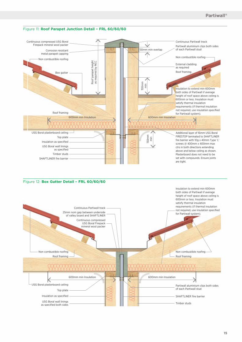
Figure 11: Roof Parapet Junction Detail – FRL 60/60/60
Figure 12: Box Gutter Detail – FRL 60/60/60
600mm min Insulation 600mm min Insulation
Non combustible roofing Non combustible roofing
25mm nom gap between underside of valley board and SHAFTLINER
Continuous compressedUSG Boral Firepack
mineral wool packer
Roof framing Roof framing
USG Boral plasterboard ceiling
Top plate
USG Boral wall liningsas specified both sides
Continuous Partiwall track
Partiwall aluminium clips both sides of each Partiwall stud
SHAFTLINER fire barrier
Timber studs
Insulation as specified
Insulation to extend min 600mm both sides of Partiwall if average height of roof space above ceiling is 600mm or less. Insulation must satisfy thermal insulation requirements (if thermal insulation not required, use insulation specified for Partiwall system).
600mm min Insulation 600mm min Insulation
Roo
f par
apet
hei
ght
as re
quire
d by
NCC
Corrosion resistant metal parapet capping
Non combustible roofing
Box gutter
Roof framing
USG Boral plasterboard ceiling
Top plate
Insulation as specified
USG Boral wall linings as specified
Timber studs
Continuous compressed USG Boral Firepack mineral wool packer
Non combustible roofing
150
mm
m
in15
0m
m
min
Partiwall aluminium clips both sides of each Partiwall stud
External cladding as required
Additional layer of 16mm USG Boral FIRESTOP laminated to SHAFTLINER fire barrier with 10g x 40mm Type 'L' screws @ 400mm x 400mm max ctrs in both directions extending above and below ceiling as shown. Plasterboard does not need to be set with compounds. Ensure joints are tight.
SHAFTLINER fire barrier
Continuous Partiwall track
50mm min overlap
Insulation to extend min 600mm both sides of Partiwall if average height of roof space above ceiling is 600mm or less. Insulation must satisfy thermal insulation requirements (if thermal insulation not required, use insulation specified for Partiwall system).
Roof framing
15
Partiwall®
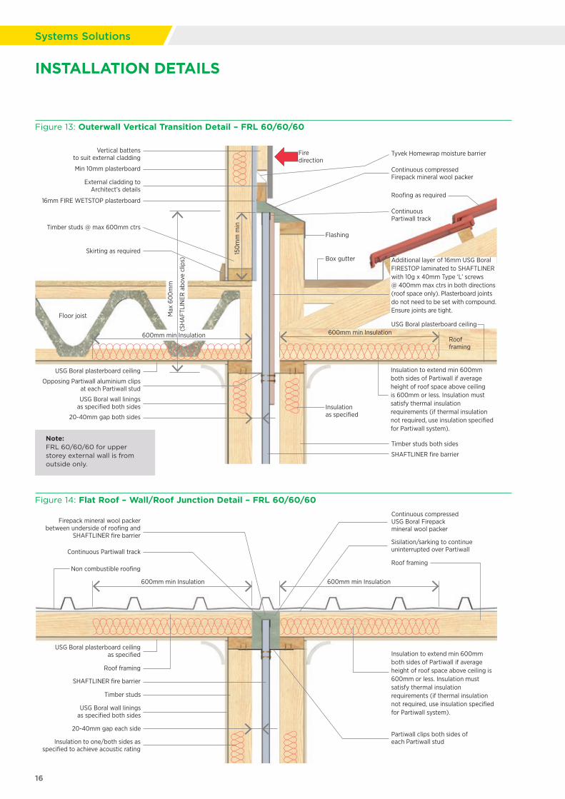
Figure 14: Flat Roof – Wall/Roof Junction Detail – FRL 60/60/60
600mm min Insulation600mm min Insulation
Roof framing
SHAFTLINER fire barrier
Timber studs
USG Boral wall linings as specified both sides
USG Boral plasterboard ceiling as specified
Insulation to one/both sides as specified to achieve acoustic rating
Partiwall clips both sides of each Partiwall stud
Insulation to extend min 600mm both sides of Partiwall if average height of roof space above ceiling is 600mm or less. Insulation must satisfy thermal insulation requirements (if thermal insulation not required, use insulation specified for Partiwall system).
Sisilation/sarking to continue uninterrupted over Partiwall
Continuous compressed USG Boral Firepack mineral wool packer
Firepack mineral wool packer between underside of roofing and
SHAFTLINER fire barrier
Continuous Partiwall track
Non combustible roofingRoof framing
20-40mm gap each side
Figure 13: Outerwall Vertical Transition Detail – FRL 60/60/60
600mm min Insulation
20-40mm gap both sides
Tyvek Homewrap moisture barrier
16mm FIRE WETSTOP plasterboard
External cladding to Architect’s details
Roofing as required
Vertical battens to suit external cladding
Continuous Partiwall track
Continuous compressed Firepack mineral wool packer
Flashing
Roof framing
USG Boral plasterboard ceiling
Opposing Partiwall aluminium clips at each Partiwall stud
SHAFTLINER fire barrier
Timber studs both sides
Timber studs @ max 600mm ctrs
Skirting as required
Floor joist
USG Boral plasterboard ceiling
USG Boral wall linings as specified both sides
Box gutter
Max
60
0m
m
(SH
AFT
LIN
ER a
bove
clip
s)
Min 10mm plasterboard
150
mm
min
Firedirection
Insulation as specified
Additional layer of 16mm USG Boral FIRESTOP laminated to SHAFTLINER with 10g x 40mm Type ‘L’ screws @ 400mm max ctrs in both directions (roof space only). Plasterboard joints do not need to be set with compound. Ensure joints are tight.
Insulation to extend min 600mm both sides of Partiwall if average height of roof space above ceiling is 600mm or less. Insulation must satisfy thermal insulation requirements (if thermal insulation not required, use insulation specified for Partiwall system).
600mm min Insulation
Note: FRL 60/60/60 for upper storey external wall is from outside only.
16
Systems Solutions
INSTALLATION DETAILS
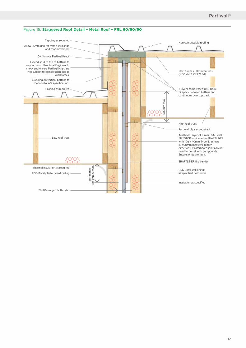
Figure 15: Staggered Roof Detail – Metal Roof – FRL 60/60/60
Cladding on vertical battens to manufacturer’s specifications
Low roof truss
Thermal insulation as required
Extend stud to top of battens to support roof. Structural Engineer to check and ensure Partiwall clips are
not subject to compression due to wind forces.
Partiwall clips as required
Additional layer of 16mm USG Boral FIRESTOP laminated to SHAFTLINER with 10g x 40mm Type 'L' screws @ 400mm max ctrs in both directions. Plasterboard joints do not need to be set with compounds. Ensure joints are tight.
High roof truss
USG Boral wall linings as specified both sides
SHAFTLINER fire barrier
Non combustible roofingCapping as required
Flashing as required
Allow 25mm gap for frame shrinkage and roof movement
Continuous Partiwall track
2 layers compressed USG Boral Firepack between battens and continuous over top track
Max 75mm x 50mm battens (NCC Vol. 2 Cl 3.7.1.8d)
USG Boral plasterboard ceiling
20-40mm gap both sides
Insulation as specified150
mm
min
Fire
stop
ove
rlap
600
mm
max
17
Partiwall®
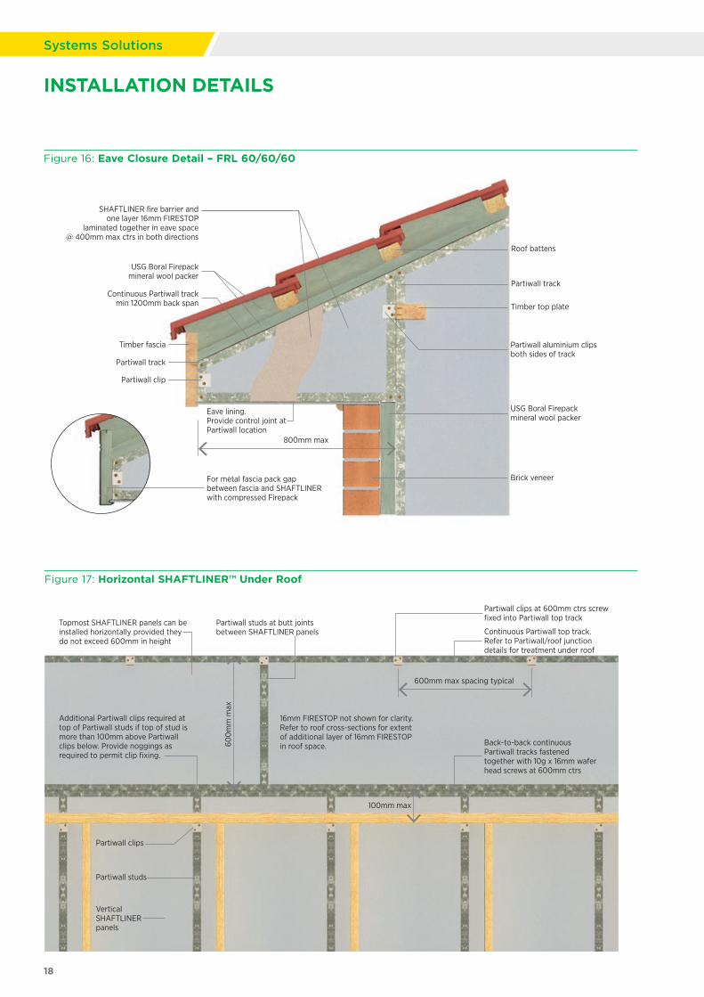
Figure 16: Eave Closure Detail – FRL 60/60/60
Figure 17: Horizontal SHAFTLINER™ Under Roof
800mm max
Eave lining. Provide control joint at Partiwall location
For metal fascia pack gap between fascia and SHAFTLINER with compressed Firepack
Timber fascia
Partiwall clip
Partiwall track
Continuous Partiwall trackmin 1200mm back span
USG Boral Firepackmineral wool packer
Brick veneer
Partiwall track
Partiwall aluminium clipsboth sides of track
USG Boral Firepack mineral wool packer
SHAFTLINER fire barrier and one layer 16mm FIRESTOP
laminated together in eave space @ 400mm max ctrs in both directions
Timber top plate
Roof battens
18
Systems Solutions
600
mm
max
600mm max spacing typical
100mm max
Topmost SHAFTLINER panels can be installed horizontally provided they do not exceed 600mm in height
Additional Partiwall clips required at top of Partiwall studs if top of stud is more than 100mm above Partiwall clips below. Provide noggings as required to permit clip fixing.
Partiwall studs at butt joints between SHAFTLINER panels
16mm FIRESTOP not shown for clarity. Refer to roof cross-sections for extent of additional layer of 16mm FIRESTOP in roof space.
Continuous Partiwall top track. Refer to Partiwall/roof junction details for treatment under roof
Partiwall clips at 600mm ctrs screw fixed into Partiwall top track
Back-to-back continuous Partiwall tracks fastened together with 10g x 16mm wafer head screws at 600mm ctrs
Vertical SHAFTLINER panels
Partiwall clips
Partiwall studs
INSTALLATION DETAILS
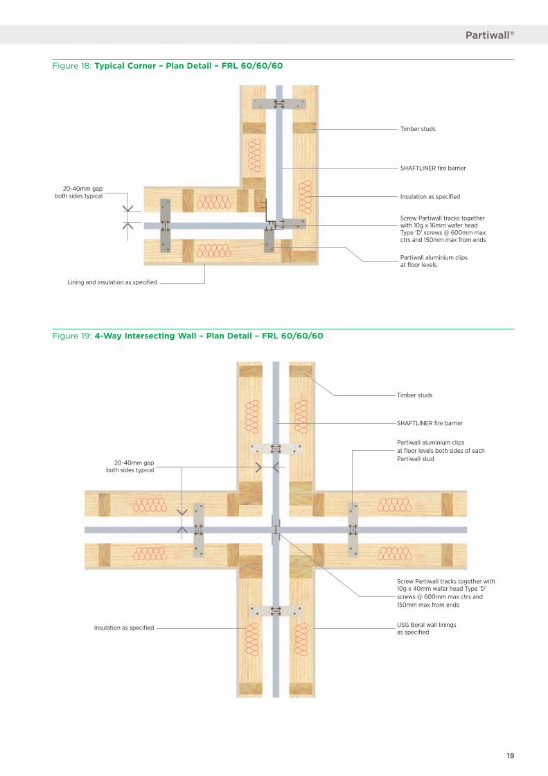
Figure 19: 4-Way Intersecting Wall – Plan Detail – FRL 60/60/60
Figure 18: Typical Corner – Plan Detail – FRL 60/60/60
Partiwall aluminium clips at floor levels both sides of each Partiwall stud
20-40mm gap both sides typical
Screw Partiwall tracks together with 10g x 40mm wafer head Type ‘D’ screws @ 600mm max ctrs and 150mm max from ends
Insulation as specified
SHAFTLINER fire barrier
Timber studs
USG Boral wall liningsas specified
Screw Partiwall tracks together with 10g x 16mm wafer head Type ‘D’ screws @ 600mm max ctrs and 150mm max from ends
Lining and insulation as specified
Timber studs
SHAFTLINER fire barrier
Insulation as specified
Partiwall aluminium clips at floor levels
20-40mm gap both sides typical
19
Partiwall®
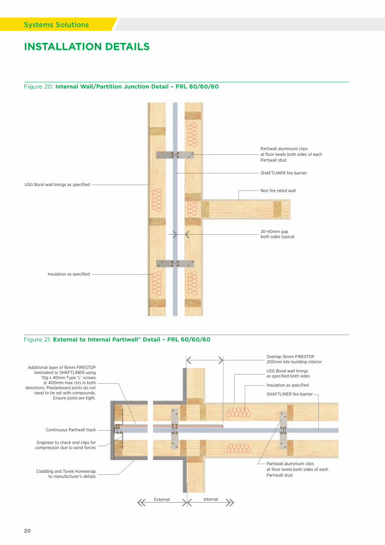
Figure 20: Internal Wall/Partition Junction Detail – FRL 60/60/60
Figure 21: External to Internal Partiwall® Detail – FRL 60/60/60
SHAFTLINER fire barrier
Non fire rated wall
Partiwall aluminium clips at floor levels both sides of each Partiwall stud
Insulation as specified
20-40mm gap both sides typical
USG Boral wall linings as specified
SHAFTLINER fire barrier
Internal
Additional layer of 16mm FIRESTOP laminated to SHAFTLINER using
10g x 40mm Type 'L' screws @ 400mm max ctrs in both
directions. Plasterboard joints do not need to be set with compounds.
Ensure joints are tight.
Cladding and Tyvek Homewrap to manufacturer’s details
Engineer to check end clips for compression due to wind forces
Continuous Partiwall track
External
USG Boral wall linings as specified both sides
Partiwall aluminium clipsat floor levels both sides of each Partiwall stud
Insulation as specified
Overlap 16mm FIRESTOP 200mm into building interior
20
Systems Solutions
INSTALLATION DETAILS
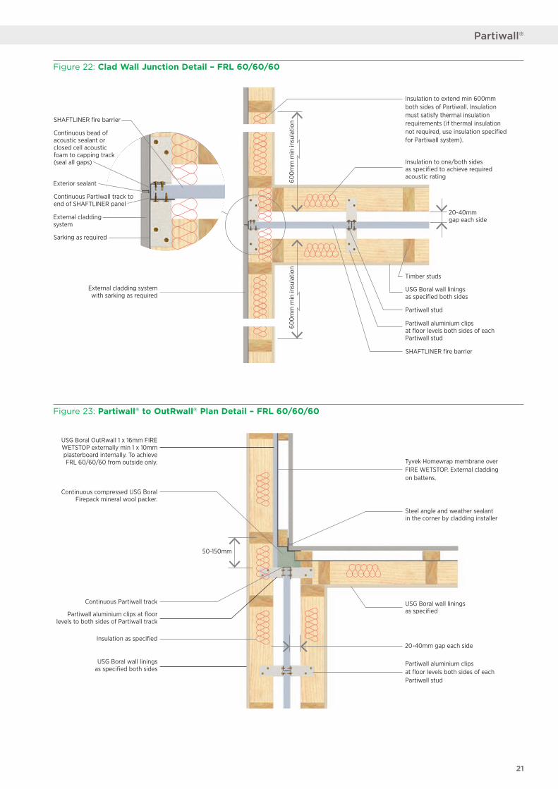
Figure 22: Clad Wall Junction Detail – FRL 60/60/60
Figure 23: Partiwall® to OutRwall® Plan Detail – FRL 60/60/60
600
mm
min
insu
latio
n60
0m
m m
in in
sula
tion
External cladding system with sarking as required
Exterior sealant
SHAFTLINER fire barrier
Continuous bead of acoustic sealant or closed cell acoustic foam to capping track (seal all gaps)
External cladding system
Sarking as required
20-40mm gap each side
USG Boral wall linings as specified both sides
Partiwall aluminium clips at floor levels both sides of each Partiwall stud
Timber studs
Insulation to one/both sides as specified to achieve required acoustic rating
Partiwall stud
SHAFTLINER fire barrier
Insulation to extend min 600mm both sides of Partiwall. Insulation must satisfy thermal insulation requirements (if thermal insulation not required, use insulation specified for Partiwall system).
Continuous Partiwall track to end of SHAFTLINER panel
USG Boral OutRwall 1 x 16mm FIRE WETSTOP externally min 1 x 10mm plasterboard internally. To achieve FRL 60/60/60 from outside only.
Continuous compressed USG Boral Firepack mineral wool packer.
20-40mm gap each side
USG Boral wall linings as specified both sides
Partiwall aluminium clips at floor levels to both sides of Partiwall track
USG Boral wall linings as specified
50-150mm
Steel angle and weather sealant in the corner by cladding installer
Tyvek Homewrap membrane over FIRE WETSTOP. External cladding on battens.
Partiwall aluminium clips at floor levels both sides of each Partiwall stud
Continuous Partiwall track
Insulation as specified
21
Partiwall®
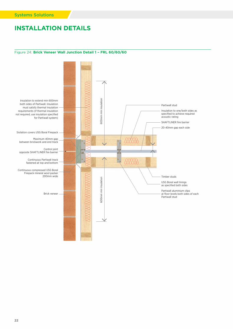
Figure 24: Brick Veneer Wall Junction Detail 1 – FRL 60/60/60
22
Systems Solutions
20-40mm gap each side
Sisilation covers USG Boral Firepack
Maximum 40mm gap between brickwork and end track
Control joint opposite SHAFTLINER fire barrier
Continuous compressed USG Boral Firepack mineral wool packer
200mm wide
Continuous Partiwall track fastened at top and bottom
Brick veneerPartiwall aluminium clips at floor levels both sides of each Partiwall stud
USG Boral wall linings as specified both sides
Timber studs
Insulation to one/both sides as specified to achieve required acoustic rating
Partiwall stud
SHAFTLINER fire barrier
Insulation to extend min 600mm both sides of Partiwall. Insulation
must satisfy thermal insulation requirements (if thermal insulation
not required, use insulation specified for Partiwall system)
600
mm
min
insu
latio
n60
0m
m m
in in
sula
tion
INSTALLATION DETAILS
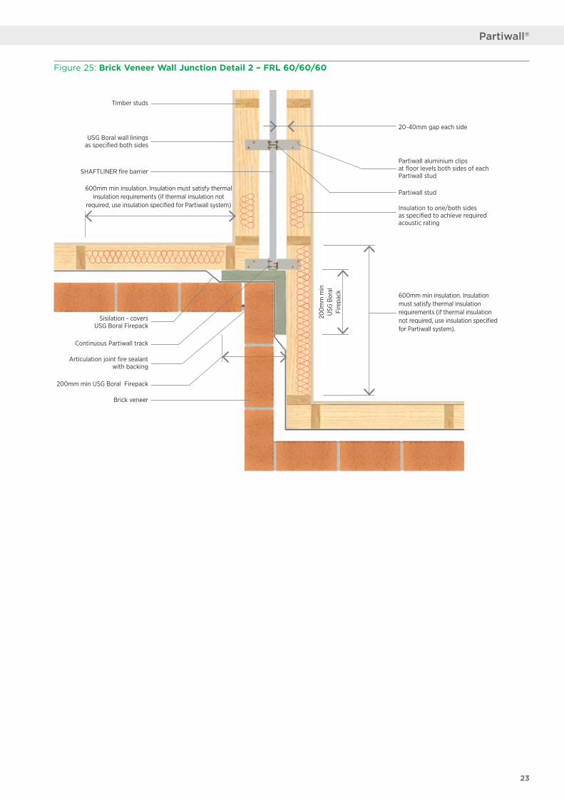
Figure 25: Brick Veneer Wall Junction Detail 2 – FRL 60/60/60
Timber studs
USG Boral wall linings as specified both sides
SHAFTLINER fire barrier
Articulation joint fire sealant with backing
Brick veneer
Partiwall stud
Partiwall aluminium clips at floor levels both sides of each Partiwall stud
Insulation to one/both sides as specified to achieve required acoustic rating
Continuous Partiwall track
Sisilation - covers USG Boral Firepack
600mm min insulation. Insulation must satisfy thermal insulation requirements (if thermal insulation not
required, use insulation specified for Partiwall system)
600mm min insulation. Insulation must satisfy thermal insulation requirements (if thermal insulation not required, use insulation specified for Partiwall system).
20-40mm gap each side
200mm min USG Boral Firepack
200m
m m
in
USG
Bor
al
Fire
pack
23
Partiwall®
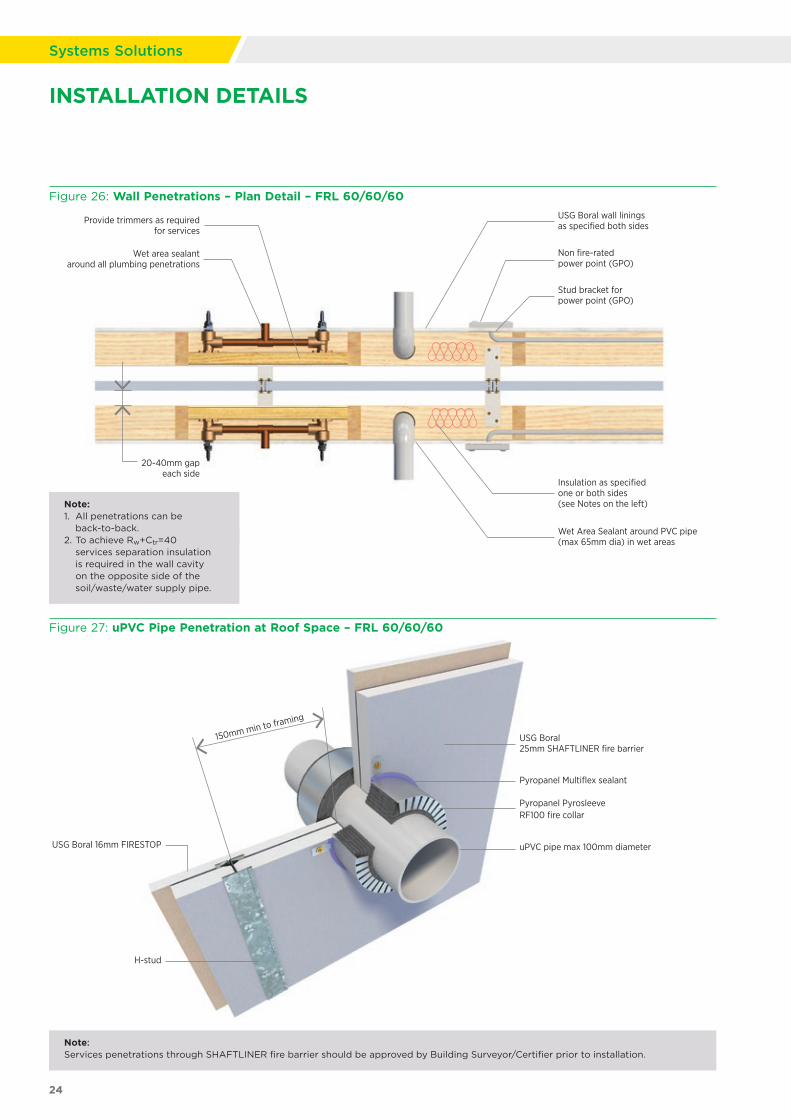
Figure 27: uPVC Pipe Penetration at Roof Space – FRL 60/60/60
Non fire-rated power point (GPO)
Stud bracket for power point (GPO)
Insulation as specifiedone or both sides(see Notes on the left)
Provide trimmers as required for services
Wet area sealant around all plumbing penetrations
Wet Area Sealant around PVC pipe (max 65mm dia) in wet areas
USG Boral wall linings as specified both sides
20-40mm gap each side
USG Boral 25mm SHAFTLINER fire barrier
USG Boral 16mm FIRESTOP
Pyropanel Multiflex sealant
Pyropanel Pyrosleeve RF100 fire collar
uPVC pipe max 100mm diameter
150mm min to framing
H-stud
Note: Services penetrations through SHAFTLINER fire barrier should be approved by Building Surveyor/Certifier prior to installation.
Figure 26: Wall Penetrations – Plan Detail – FRL 60/60/60
Note: 1. All penetrations can be
back-to-back.2. To achieve Rw+Ctr=40
services separation insulation is required in the wall cavity on the opposite side of the soil/waste/water supply pipe.
24
Systems Solutions
INSTALLATION DETAILS
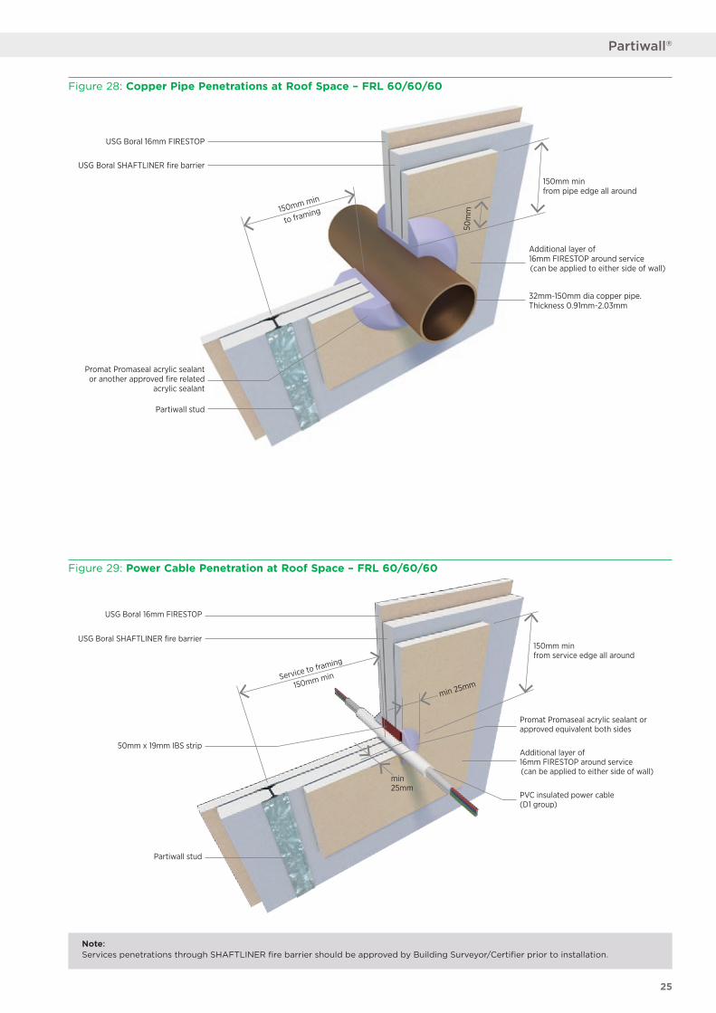
Note: Services penetrations through SHAFTLINER fire barrier should be approved by Building Surveyor/Certifier prior to installation.
Figure 28: Copper Pipe Penetrations at Roof Space – FRL 60/60/60
Figure 29: Power Cable Penetration at Roof Space – FRL 60/60/60
USG Boral SHAFTLINER fire barrier
USG Boral 16mm FIRESTOP
32mm-150mm dia copper pipe. Thickness 0.91mm-2.03mm
Promat Promaseal acrylic sealant or another approved fire related
acrylic sealant
50m
m
Partiwall stud
150mm min from pipe edge all around
Additional layer of16mm FIRESTOP around service(can be applied to either side of wall)
150mm min
to framing
USG Boral SHAFTLINER fire barrier
USG Boral 16mm FIRESTOP
50mm x 19mm IBS strip
Promat Promaseal acrylic sealant or approved equivalent both sides
PVC insulated power cable (D1 group)
min25mm
min 25mm
Partiwall stud
Service to framing
150mm min
150mm min from service edge all around
Additional layer of16mm FIRESTOP around service(can be applied to either side of wall)
25
Partiwall®
© 2018 USG BORAL. All rights reserved. The trademarks USG BORAL, INNOVATION INSPIRED BY YOU, Partiwall, Multiframe, IntRwall, TecASSIST, SOUNDSTOP, FIRESTOP, SHAFTLINER, WETSTOP, FIRE+WETSTOP, FIREPACK and Wet Area Sealant are trademarks or registered trademarks of USG Boral Building Products or one or more of its affiliates. SHEETROCK and FIBEROCK Aqua-Tough are trademarks owned by United States Gypsum Company and used under license. VILLABOARD is a registered mark of James Hardie Technology Limited. FIRESOUND is a trademark of HB Fuller. TRACK-IT is a registered trademark of Powers Fasteners Australasia Pty Ltd. TYVEK HOMEWRAP is a registered trademark of E. I. du Pont de Nemours and Company or its affiliates. PROMASEAL is a registered trademark of PROMAT GMBH. PYROSLEEVE and MULTIFLEX are trademarks or registered trademarks of Pyropanel Developments Pty Ltd. USG Boral Building Products Pty Limited – ABN 84 004 231 976 251 Salmon Street, Port Melbourne, VIC. 3207
UB1037-SYS 08/18
PRODUCT INFORMATIONSee USGBoral.com for the most up-to-date product information.
SALES ENQUIRIES1800 003 377
TECHNICAL ASSISTANCETecASSIST™ – 1800 811 222
There are many variables that can influence construction projects, which affect whether a particular construction technique is appropriate. Before proceeding with any project, we recommend you obtain professional advice to ascertain the appropriate construction techniques to suit the particular circumstances of your project. We recommend you use qualified tradespersons to install this system.
The technical information contained in this manual was correct at the time of printing. Building systems, details and product availability are, however, subject to change. To ensure the information you are using is current, USG Boral recommends you review the latest building information available on the USG Boral website.
AustraliaChinaIndiaIndonesiaMalaysiaMiddle EastNew ZealandThailandPhilippinesSingaporeSouth KoreaVietnam
USG Boral Building Products Pty Ltd251 Salmon Street Port Melbourne Victoria 3207 Australia
USGBoral.com Interior Linings Ceilings Cornice Finishes Systems SolutionsUSGBoral.com Interior Linings Ceilings Cornice Finishes Systems Solutions


![September 2015 Generic Seismic Design - USG Boral · SEISMIC DESIGN STATEMENT Jacobs (formerly Sinclair Knight Merz [SKM]) has provided USG Boral with structural design services in](https://img.pdfslide.net/doc/110x75/5e6da852d29167699605df08/september-2015-generic-seismic-design-usg-boral-seismic-design-statement-jacobs.jpg)