Embed Size (px)
Citation preview
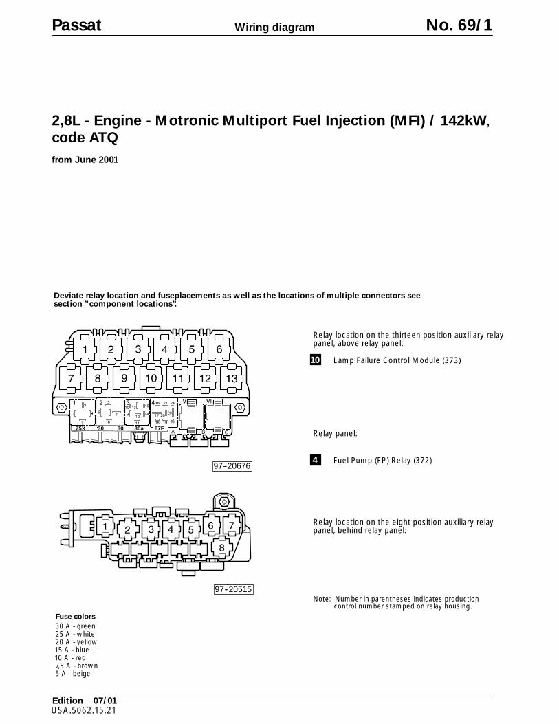
Deviate relay location and fuseplacements as well as the locations of multiple connectors seesection ”component locations”.
Fuse colors
30 A - green25 A - white20 A - yellow15 A - blue10 A - red7,5 A - brown5 A - beige
Wiring diagram
A97--0031
97--20515
97--20676
75X 3030 30a 87F
Relay location on the thirteen position auxiliary relaypanel, above relay panel:
Relay location on the eight position auxiliary relaypanel, behind relay panel:
Note: Number in parentheses indicates productioncontrol number stamped on relay housing.
Relay panel:
10 Lamp Failure Control Module (373)
4 Fuel Pump (FP) Relay (372)
Edition 07/01USA.5062.15.21
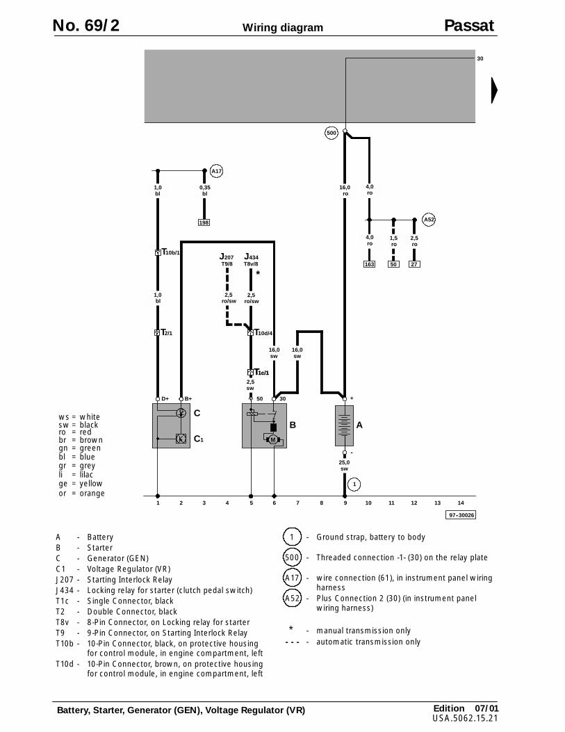
Passat No. 69/1
2,8L - Engine - Motronic Multiport Fuel Injection (MFI) / 142kW,code ATQ
from June 2001
Edition 07/01USA.5062.15.21
Wiring diagram
ws = whitesw = blackro = redbr = browngn = greenbl = bluegr = greyli = lilacge = yellowor = orange
Battery, Starter, Generator (GEN), Voltage Regulator (VR)
D+
G
B+
C
C1
B
30
1
97--30026
M
50
2 3 4 5 6 7 8 9 10 11 12 13 14
1
bl1,0
A17
sw25,0
sw16,0
J434
ro/sw2,5
sw16,0
30
4,0ro
16,0ro
A
+
--
T10d/4
T10b/1
198
500
bl0,35
bl1,0
4,0ro
163
T1c/1T1c/1
T2/1
ro/sw2,5
J207T9/8
ro1,5
50
sw2,5
A52
ro2,5
27T8v/8
*
No. 69/2 Passat
A - BatteryB - StarterC - Generator (GEN)C1 - Voltage Regulator (VR)J207 - Starting Interlock RelayJ434 - Locking relay for starter (clutch pedal switch)T1c - Single Connector, blackT2 - Double Connector, blackT8v - 8-Pin Connector, on Locking relay for starterT9 - 9-Pin Connector, on Starting Interlock RelayT10b - 10-Pin Connector, black, on protective housing
for control module, in engine compartment, leftT10d - 10-Pin Connector, brown, on protective housing
for control module, in engine compartment, left
1 - Ground strap, battery to body
500 - Threaded connection -1- (30) on the relay plate
A17 - wire connection (61), in instrument panel wiringharness
A52 - Plus Connection 2 (30) (in instrument panelwiring harness)
* - manual transmission only- - - - automatic transmission only

Edition 07/01USA.5062.15.21
Wiring diagram
ws = whitesw = blackro = redbr = browngn = greenbl = bluegr = greyli = lilacge = yellow
Motronic Engine Control Module (ECM), Throttle Valve Control Module,Ignition Coil, Throttle drive, Spark Plug Connectors, Suppressor
ge = yellowor = orange
J220
15 16 17 18 19 20 21 22 23 24 25 26 27 28
97--30027
PQ
T5e/2
N152T5e/1 T5e/5 T5e/4
br2,5
T121/94
gn/gr0,35
T121/103
gn/ws0,35
T5e/3
T121/102
gr/ge0,35
3030
T10e/1
ro/gn2,5
S22920A
29
29a
ro/gn2,5
T10b/8
S3/6
ro/bl0,5
S3/4
gn/sw2,5
159
4
19/15
16/S20/87a
J17
17/30
23/87F
S3/3
T121/65
504
gn2,5
87F
179
ro/bl0,35
12
T121/118
T6a/5 T6a/3 T6a/2 T6a/1T6a/6 T6a/4
J338
G187G186 G188
T121/117
T121/83
T121/92T121/91
T121/84
sw/ro0,35
sw0,35
br/li1,0
gr/ws0,35
ro/li1,0
ws/ge0,35
gn/li0,35
li/ro0,35
ro2,5
C5
D52
A106
M
0,75
Passat No. 69/3
C5 - Suppressor (Terminal 15)G186 - Throttle drive (power accelerator actuation)G187 - Angle sensor -1- for throttle drive (power
accelerator actuation)G188 - Angle sensor -2- for throttle drive (power
accelerator actuation)J17 - Fuel Pump (FP) RelayJ220 - Motronic Engine Control Module (ECM)J338 - Throttle Valve Control ModuleN152 - Ignition CoilP - Spark Plug ConnectorsQ - Spark PlugsS229 - Fuse in fuse holderT5e - 5-Pin Connector, black, on Ignition CoilT6a - 6-Pin Connector, black, on Throttle Valve
Control Module
T10b - 10-Pin Connector, black, on protective housingfor control module, in engine compartment, left
T10e - 10-Pin Connector, orange, on protectivehousing for control module, in enginecompartment, left
T121 - Connector, 121 point, on Motronic EngineControl Module (ECM)
504 - Threaded connection -1- (87) on the relay plate
A106 - Connector -2- (86s), in instrument panel wiringharness
D52 - plus connection (15a), in engine compartmentwiring harness
Edition 07/01USA.5062.15.21
Wiring diagram
ws = whitesw = blackro = redbr = browngn = greenbl = bluegr = greyli = lilacge = yellowor = orange
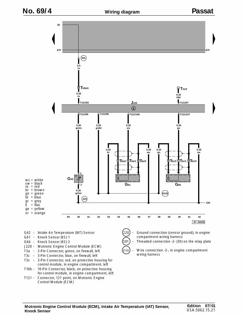
Motronic Engine Control Module (ECM), Intake Air Temperature (IAT) Sensor,Knock Sensor
J220
29 30 31 32 33 34 35 36 37 38 39 40 41 42
97--30028
G66
T3c/1 T3c/3
T121/107
T3c/2
ge0,35
sw0,35
gn0,35
G61
T3a/1 T3a/3
T121/106
T3a/2
ws0,35
br0,35
220
30
ro2,5
T121/62
T10b/4
501
D102
220
sw0,35
87F87F
T121/67
T3s/2
li/bl0,35ro
0,35
1
2
G42
gr/ws0,35
T121/85
gn/ro0,35
T121/99
gn/br0,35
No. 69/4 Passat
G42 - Intake Air Temperature (IAT) SensorG61 - Knock Sensor (KS) 1G66 - Knock Sensor (KS) 2J220 - Motronic Engine Control Module (ECM)T3a - 3-Pin Connector, green, on firewall, leftT3c - 3-Pin Connector, blue, on firewall, leftT3s - 3-Pin Connector, red, on protective housing for
control module, in engine compartment, leftT10b - 10-Pin Connector, black, on protective housing
for control module, in engine compartment, leftT121 - Connector, 121 point, on Motronic Engine
Control Module (ECM)
220 - Ground connection (sensor ground), in enginecompartment wiring harness
501 - Threaded connection -2- (30) on the relay plate
D102 - Wire connection -2-, in engine compartmentwiring harness
Edition 07/01USA.5062.15.21
Wiring diagram
ws = whitesw = blackro = redbr = browngn = greenbl = bluegr = greyli = lilacge = yellow
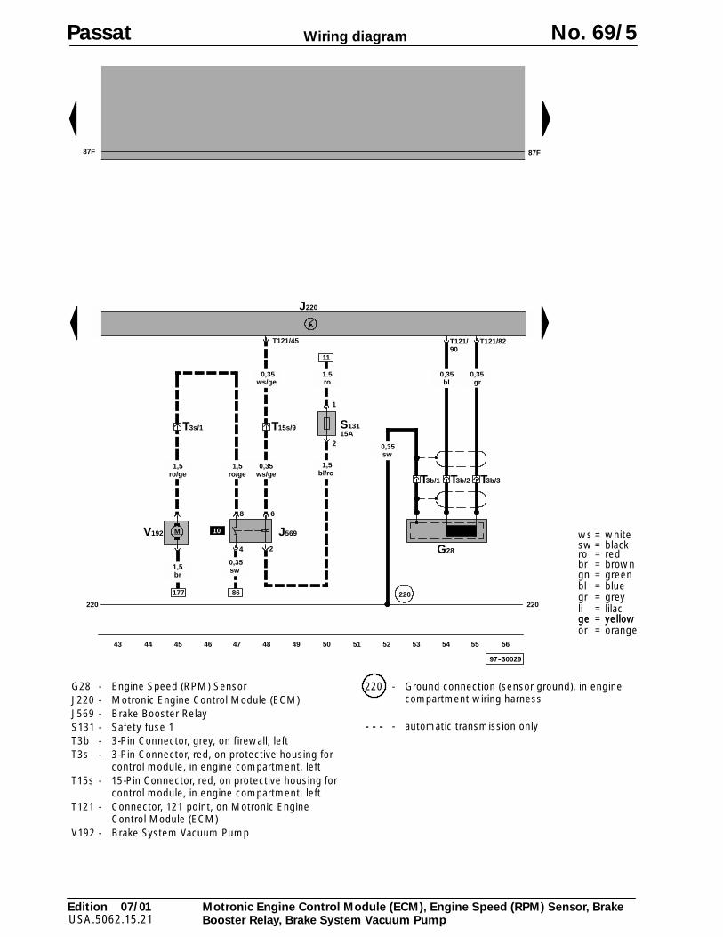
Motronic Engine Control Module (ECM), Engine Speed (RPM) Sensor, BrakeBooster Relay, Brake System Vacuum Pump
ge = yellowor = orange
br1,5
43 44 45 46 47 48 49 50 51 52 53 54 55 56
97--30029
J220
87F 87F
220220
M
86
S131
68
2
J569
4
T15s/9
T121/45
ws/ge0,35
11
bl/ro1,5
T3s/1
ws/ge0,35
sw0,35
177
V192
ro/ge1,5
2
1
220
ro1.5
15A
0,35sw
T3b/2 T3b/3T3b/1
G28
T121/90
T121/82
bl0,35
gr0,35
10
ro/ge1,5
Passat No. 69/5
G28 - Engine Speed (RPM) SensorJ220 - Motronic Engine Control Module (ECM)J569 - Brake Booster RelayS131 - Safety fuse 1T3b - 3-Pin Connector, grey, on firewall, leftT3s - 3-Pin Connector, red, on protective housing for
control module, in engine compartment, leftT15s - 15-Pin Connector, red, on protective housing for
control module, in engine compartment, leftT121 - Connector, 121 point, on Motronic Engine
Control Module (ECM)V192 - Brake System Vacuum Pump
220 - Ground connection (sensor ground), in enginecompartment wiring harness
- - - - automatic transmission only
Edition 07/01USA.5062.15.21
Wiring diagram
ws = whitesw = blackro = redbr = browngn = greenbl = bluegr = greyli = lilacge = yellowor = orange
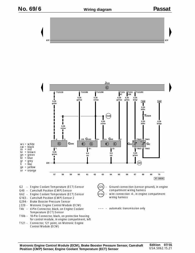
Motronic Engine Control Module (ECM), Brake Booster Pressure Sensor, CamshaftPosition (CMP) Sensor, Engine Coolant Temperature (ECT) Sensor
J220
57 58 59 60 61 62 63 64 65 66 67 68 69 70
97--30030
220
G40 2
T121/108
T4k/4 T4k/1
T4k/3 T4k/2
G62 G2
220
200
bl/br0.35
T121/93
gr/ws0,35br/gr
0,35
T121/87
gn/sw0,35
1/+
gr/ws0,35
3/--
sw0,5
T10b/9
bl/br0,35
G163
T121/86
1/+
0,35
3/--
T121/98
ro/sw0,35
br/ge0,35
189
D106
87F87F
sw0,5
ge/sw0,35ro/sw
2/S
gr/ws0,35
gn/br0,35
T121/18
1
3
ro/sw0,35
4
G294
No. 69/6 Passat
G2 - Engine Coolant Temperature (ECT) SensorG40 - Camshaft Position (CMP) SensorG62 - Engine Coolant Temperature (ECT) SensorG163 - Camshaft Position (CMP) Sensor 2G294 - Brake Booster Pressure SensorJ220 - Motronic Engine Control Module (ECM)T4k - 4-Pin Connector, black, on Engine Coolant
Temperature (ECT) SensorT10b - 10-Pin Connector, black, on protective housing
for control module, in engine compartment, leftT121 - Connector, 121 point, on Motronic Engine
Control Module (ECM)
220 - Ground connection (sensor ground), in enginecompartment wiring harness
D106 - wire connection -4-, in engine compartmentwiring harness
- - - - automatic transmission only
Edition 07/01USA.5062.15.21
Wiring diagram
ws = whitesw = blackro = redbr = browngn = greenbl = bluegr = greyli = lilacge = yellow
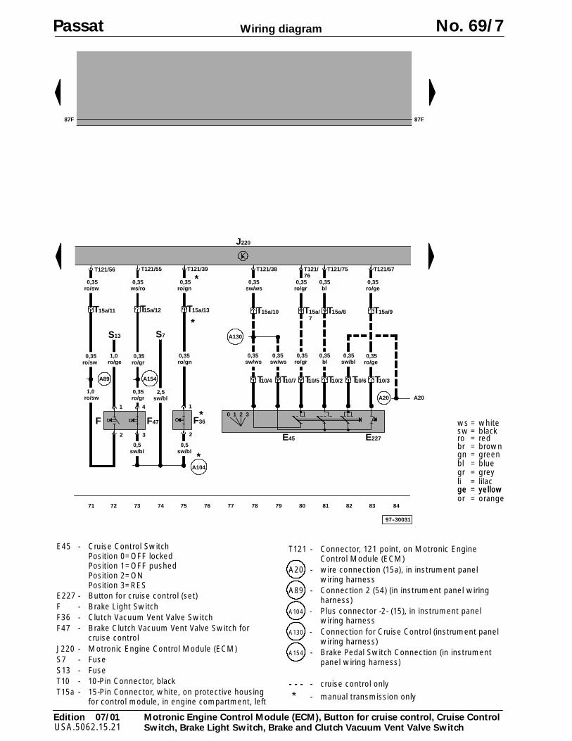
Motronic Engine Control Module (ECM), Button for cruise control, Cruise ControlSwitch, Brake Light Switch, Brake and Clutch Vacuum Vent Valve Switch
ge = yellowor = orange
J220
10/3TT10/7T10/4 T10/5 T T10/610/2
0 1 2 3
E45
T15a/9
0,35ro/ge
T121/57
T15a/8
0,35bl
T121/75
T15a/7
0,35ro/gr
T121/76
T15a/10
0,35sw/ws
T121/38
0,35sw/ws
0,35sw/bl
0,35sw/ws
E227
0,35ro/gr
0,35bl
A130
97--30031
71 72 73 74 75 76 77 78 79 80 81 82 83 84
87F87F
F47
4
3
0,35ws/ro
1
2
F
T15a/11
0,35ro/sw
T121/56
A89
S13
1,0ro/ge
1,0ro/sw
0,35ro/sw
0,35ro/gr
0,35ro/gr
0,5sw/bl
A154
F36
1
2
T15a/13T15a/12
0,5sw/bl
0,35ro/gn
T121/39
A104
*
*
*
0,35ro/gn
S7
*
A20A20
0,35ro/ge
T121/55
2,5sw/bl
Passat No. 69/7
E45 - Cruise Control SwitchPosition 0=OFF lockedPosition 1=OFF pushedPosition 2=ONPosition 3=RES
E227 - Button for cruise control (set)F - Brake Light SwitchF36 - Clutch Vacuum Vent Valve SwitchF47 - Brake Clutch Vacuum Vent Valve Switch for
cruise controlJ220 - Motronic Engine Control Module (ECM)S7 - FuseS13 - FuseT10 - 10-Pin Connector, blackT15a - 15-Pin Connector, white, on protective housing
for control module, in engine compartment, left
T121 - Connector, 121 point, on Motronic EngineControl Module (ECM)
A20 - wire connection (15a), in instrument panelwiring harness
A89 - Connection 2 (54) (in instrument panel wiringharness)
A104 - Plus connector -2- (15), in instrument panelwiring harness
A130 - Connection for Cruise Control (instrument panelwiring harness)
A154 - Brake Pedal Switch Connection (in instrumentpanel wiring harness)
- - - - cruise control only
* - manual transmission only
Edition 07/01USA.5062.15.21
Wiring diagram
ws = whitesw = blackro = redbr = browngn = greenbl = bluegr = greyli = lilacge = yellowor = orange
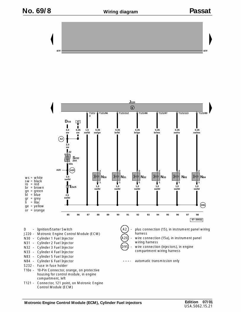
Motronic Engine Control Module (ECM), Cylinder Fuel injectors
T10e/5
D95
T121/96
2
1
N30
T121/112
2
1
N31
T121/88
2
1
N32
T121/89
2
1
N84
97--30032
sw/gn0,35
br/bl0,35
br/gn0,35
sw/ws0,35
sw/bl2,5
sw/bl1,0
sw/bl1,0
sw/bl1,0
sw/bl1,0
T121/97
2
1
N33
T121/113
2
1
N83
br/ws0,35
sw/ro0,35
sw/bl1,0
sw/bl1,0
J220
sw/bl2,5
T121/3
sw/bl1,5
A20
S232
32
32a
2,5sw
20A
87F87F
A2
sw4,0
D/15 47
0,35sw
85 86 87 88 89 90 91 92 93 94 95 96 97 98
A20
No. 69/8 Passat
D - Ignition/Starter SwitchJ220 - Motronic Engine Control Module (ECM)N30 - Cylinder 1 Fuel InjectorN31 - Cylinder 2 Fuel InjectorN32 - Cylinder 3 Fuel InjectorN33 - Cylinder 4 Fuel InjectorN83 - Cylinder 5 Fuel InjectorN84 - Cylinder 6 Fuel InjectorS232 - Fuse in fuse holderT10e - 10-Pin Connector, orange, on protective
housing for control module, in enginecompartment, left
T121 - Connector, 121 point, on Motronic EngineControl Module (ECM)
A2 - plus connection (15), in instrument panel wiringharness
A20 - wire connection (15a), in instrument panelwiring harness
D95 - wire connection (injectors), in enginecompartment wiring harness
- - - - automatic transmission only
Edition 07/01USA.5062.15.21
Wiring diagram
ws = whitesw = blackro = redbr = browngn = greenbl = bluegr = greyli = lilacge = yellow
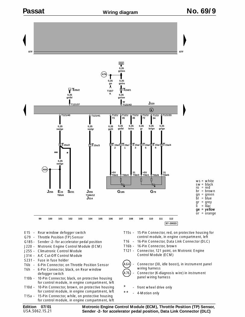
Motronic Engine Control Module (ECM), Throttle Position (TP) Sensor,Sender -2- for accelerator pedal position, Data Link Connector (DLC)
ge = yellowor = orange
J220
97--30033
87F87F
WT121/43
T
gn/sw0,35
T121/37
T
gn/bl0,35
10b/2
T121/73
T6b/4 T6b/5T6b/3T6b/2 T6b/1
T121/35
T121/36
T6b/6
0,35ge/bl
T15a/1
T15a/415a/3
15a/2
T15a/5
TT
0,35gr/ge
0,35br/ro
0,35gr
0,35ge/li
T121/33
0,35br/gn
T15a/6
T121/34
G79
T121/72
+5V 31 +5V 31
202
10d/1
G185
99 100 101 102 103 104 105 106 107 108 109 110 111 112
T121/40
15s/2T
0,35sw/ge
T121/41
15s/3T
0,35sw/gr
E15 J255
J314T16b/12T6h/4
** *
S231
A64
A76
T16/7
gn/ro0,35
gn/ws0,35
gn0,35
K
J255
0,35sw/ge
Passat No. 69/9
E15 - Rear window defogger switchG79 - Throttle Position (TP) SensorG185 - Sender -2- for accelerator pedal positionJ220 - Motronic Engine Control Module (ECM)J255 - Climatronic Control ModuleJ314 - A/C Cut-Off Control ModuleS231 - Fuse in fuse holderT6b - 6-Pin Connector, on Throttle Position SensorT6h - 6-Pin Connector, black, on Rear window
defogger switchT10b - 10-Pin Connector, black, on protective housing
for control module, in engine compartment, leftT10d - 10-Pin Connector, brown, on protective housing
for control module, in engine compartment, leftT15a - 15-Pin Connector, while, on protective housing
for control module, in engine compartment, left
T15s - 15-Pin Connector, red, on protective housing forcontrol module, in engine compartment, left
T16 - 16-Pin Connector, Data Link Connector (DLC)T16b - 16-Pin Connector, brownT121 - Connector, 121 point, on Motronic Engine
Control Module (ECM)
A64 - Connector (30, idle boost), in instrument panelwiring harness
A76 - Connector (K-diagnosis wire) in instrumentpanel wiring harness
* - front wheel drive only
** - 4-Motion only
97--30034
87F 87F
J220
1
2
N80
T121/64
li0,35
gn/ge1,0
1
2
N156
T121/104
ge/ws0,35
gn/ge0,5
1
2
N205
T121/115
br/gr1,0
gn/ge1,0
1
2
N208
gn/ge1,0
br/gr1,0
E30
113 114 115 116 117 118 119 120 121 122 123 124 125 126
E30
1 4
G70
T121/29
bl/gn0,35
gn0,35
3sw
0,35
T121/27
ge0,35
D107
ge1,0
2
T121/53
gn/ge0,5
D101D101
D103
Edition 07/01USA.5062.15.21
Wiring diagram
ws = whitesw = blackro = redbr = browngn = greenbl = bluegr = greyli = lilacge = yellowor = orange
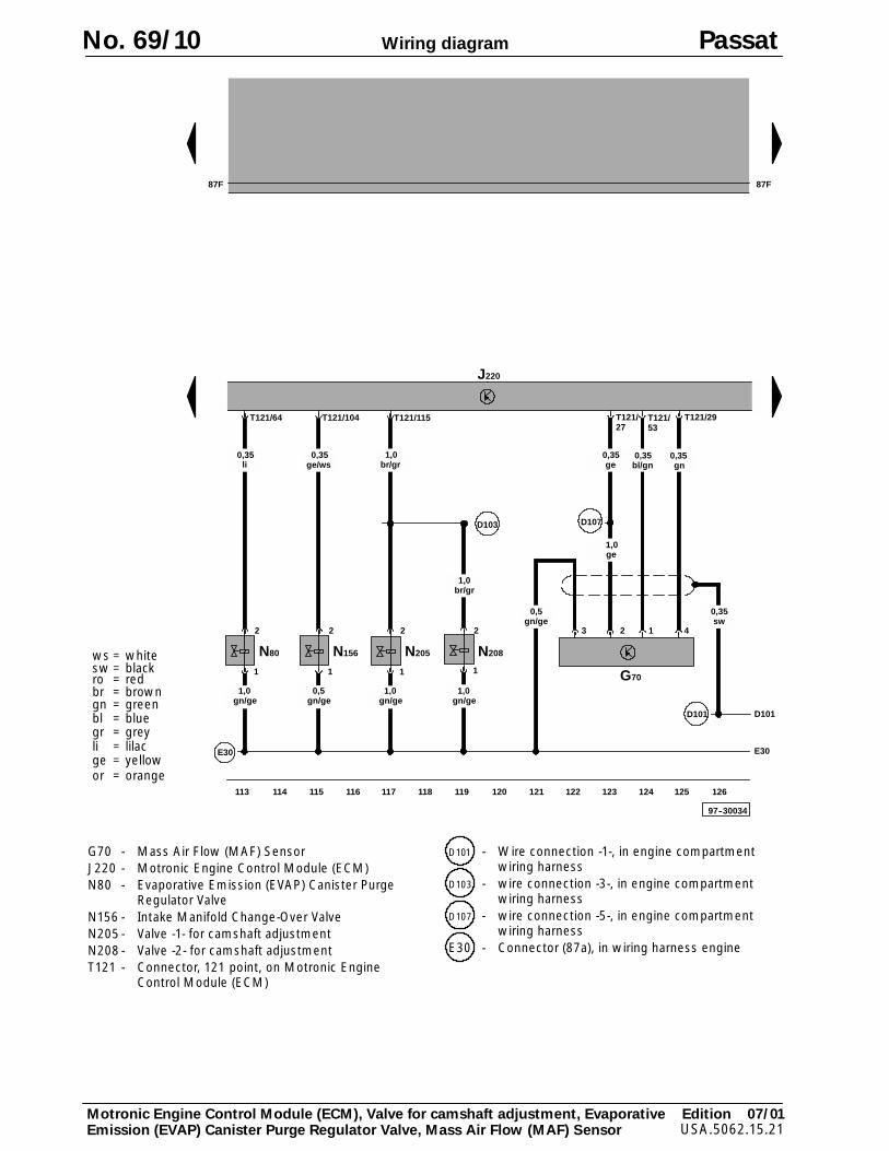
Motronic Engine Control Module (ECM), Valve for camshaft adjustment, EvaporativeEmission (EVAP) Canister Purge Regulator Valve, Mass Air Flow (MAF) Sensor
No. 69/10 Passat
G70 - Mass Air Flow (MAF) SensorJ220 - Motronic Engine Control Module (ECM)N80 - Evaporative Emission (EVAP) Canister Purge
Regulator ValveN156 - Intake Manifold Change-Over ValveN205 - Valve -1- for camshaft adjustmentN208 - Valve -2- for camshaft adjustmentT121 - Connector, 121 point, on Motronic Engine
Control Module (ECM)
D101 - Wire connection -1-, in engine compartmentwiring harness
D103 - wire connection -3-, in engine compartmentwiring harness
D107 - wire connection -5-, in engine compartmentwiring harness
E30 - Connector (87a), in wiring harness engine
Edition 07/01USA.5062.15.21
Wiring diagram
ws = whitesw = blackro = redbr = browngn = greenbl = bluegr = greyli = lilacge = yellow
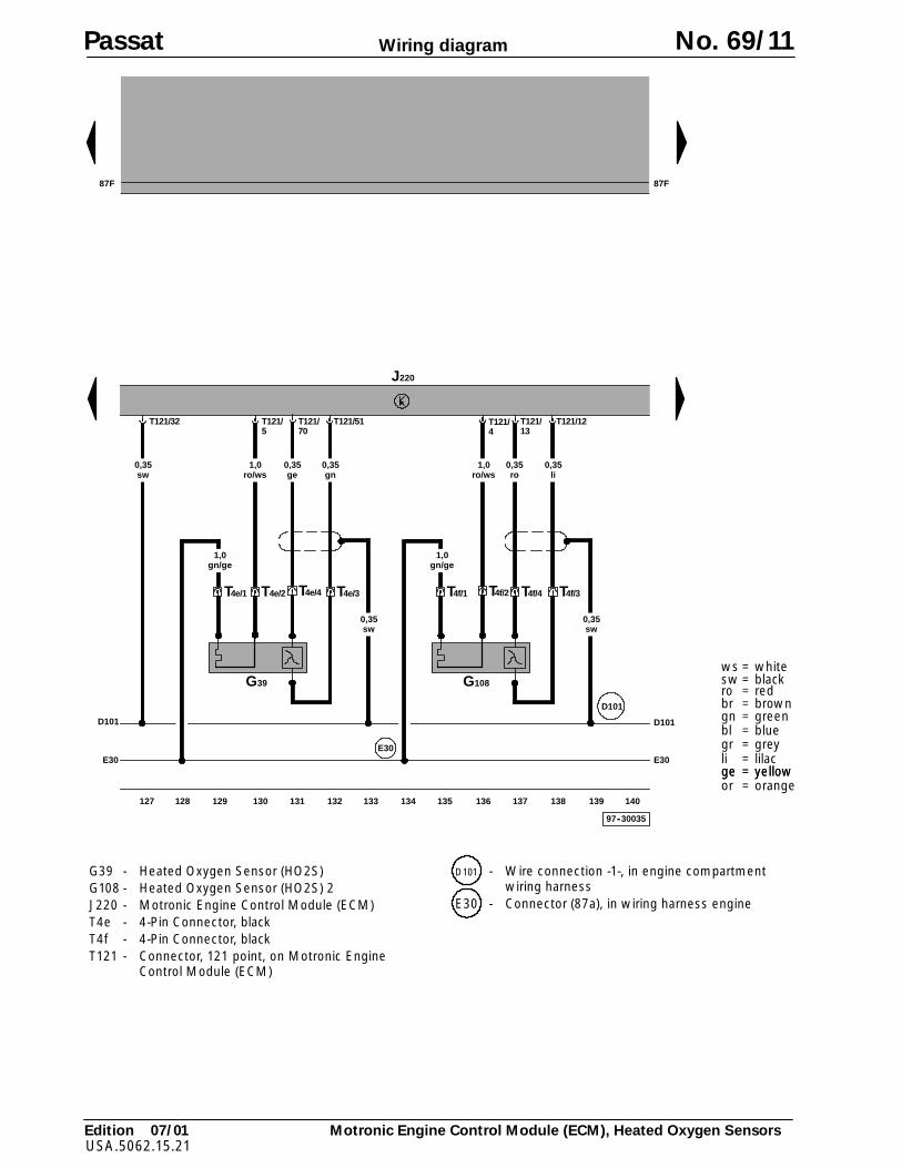
Motronic Engine Control Module (ECM), Heated Oxygen Sensors
ge = yellowor = orange
97--30035
T121/32
G39
T4e/2 T4e/3
T121/5
T121/51
T4e/1
E30
gn0,35
sw0,35
ro/ws1,0
sw0,35
G108
T4f/4 T4f/3
T121/4
T121/12
T4f/1
li0,35
sw0,35
ro/ws1,0
gn/ge1,0
gn/ge1,0
D101
E30
J220
T4e/4
T121/70
ge0,35
T4f/2
T121/13
ro0,35
87F87F
E30
127 128 129 130 131 132 133 134 135 136 137 138 139 140
D101D101
Passat No. 69/11
G39 - Heated Oxygen Sensor (HO2S)G108 - Heated Oxygen Sensor (HO2S) 2J220 - Motronic Engine Control Module (ECM)T4e - 4-Pin Connector, blackT4f - 4-Pin Connector, blackT121 - Connector, 121 point, on Motronic Engine
Control Module (ECM)
D101 - Wire connection -1-, in engine compartmentwiring harness
E30 - Connector (87a), in wiring harness engine
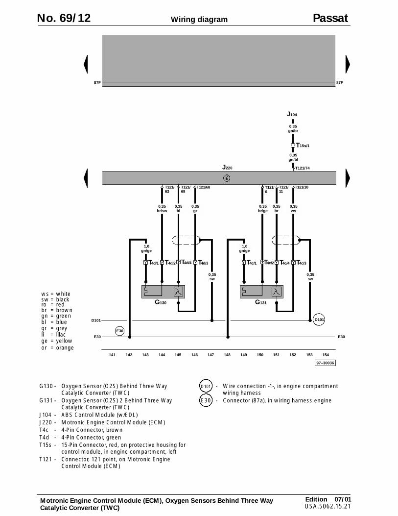
97--30036
G130
T4d/2 T4d/3
T121/63
T121/68
T4d/1
E30
gr0,35
sw0,35
br/sw0,35
G131
T4c/4 T4c/3
T121/6
T121/10
T4c/1
ws0,35
br/ge0,35
gn/ge1,0
gn/ge1,0
E30
J220
T4d/4
T121/69
bl0,35
T4c/2
T121/11
br0,35
87F87F
E30
T121/74
J104
T15s/1
gn/bl0,35
sw0,35
D101D101
141 142 143 144 145 146 147 148 149 150 151 152 153 154
gn/br0,35
Edition 07/01USA.5062.15.21
Wiring diagram
ws = whitesw = blackro = redbr = browngn = greenbl = bluegr = greyli = lilacge = yellowor = orange
Motronic Engine Control Module (ECM), Oxygen Sensors Behind Three WayCatalytic Converter (TWC)
No. 69/12 Passat
G130 - Oxygen Sensor (O2S) Behind Three WayCatalytic Converter (TWC)
G131 - Oxygen Sensor (O2S) 2 Behind Three WayCatalytic Converter (TWC)
J104 - ABS Control Module (w/EDL)J220 - Motronic Engine Control Module (ECM)T4c - 4-Pin Connector, brownT4d - 4-Pin Connector, greenT15s - 15-Pin Connector, red, on protective housing for
control module, in engine compartment, leftT121 - Connector, 121 point, on Motronic Engine
Control Module (ECM)
D101 - Wire connection -1-, in engine compartmentwiring harness
E30 - Connector (87a), in wiring harness engine
Edition 07/01USA.5062.15.21
Wiring diagram
ws = whitesw = blackro = redbr = browngn = greenbl = bluegr = greyli = lilacge = yellowge = yellowor = orange
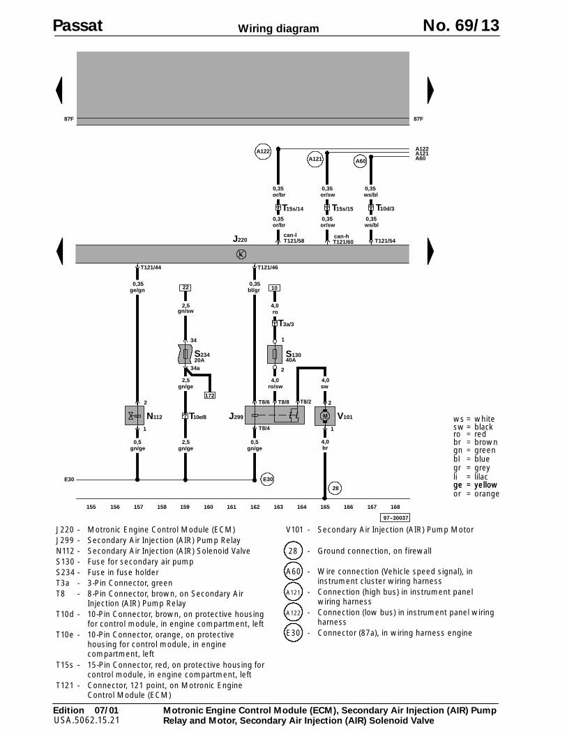
Motronic Engine Control Module (ECM), Secondary Air Injection (AIR) PumpRelay and Motor, Secondary Air Injection (AIR) Solenoid Valve
97--30037
87F 87F
J220
155 156 157 158 159 160 161 162 163 164 165 166 167 168
E30 E30
S234
34
34a
gn/ge2,5
gn/sw2,5
22
T10e/8
gn/ge2,5
20A
T3a/3
gn/ge0,5
J299
T8/8T8/6
T8/4
T8/2
T121/46
bl/gr0,35
V101
2
M
sw4,0
1
br
28
ro4,0
1
2
N112
T121/44
ge/gn0,35
gn/ge0,5 4,0
10
S13040A
ro/sw4,0
1
2
172
T10d/3
T121/54
T15s/15
or/sw0,35
T121/60
A121
T15s/14
or/br0,35
T121/58
A122
A60
or/sw0,35
or/br0,35
can-hcan-l
ws/bl0,35
ws/bl0,35
A122A121A60
Passat No. 69/13
J220 - Motronic Engine Control Module (ECM)J299 - Secondary Air Injection (AIR) Pump RelayN112 - Secondary Air Injection (AIR) Solenoid ValveS130 - Fuse for secondary air pumpS234 - Fuse in fuse holderT3a - 3-Pin Connector, greenT8 - 8-Pin Connector, brown, on Secondary Air
Injection (AIR) Pump RelayT10d - 10-Pin Connector, brown, on protective housing
for control module, in engine compartment, leftT10e - 10-Pin Connector, orange, on protective
housing for control module, in enginecompartment, left
T15s - 15-Pin Connector, red, on protective housing forcontrol module, in engine compartment, left
T121 - Connector, 121 point, on Motronic EngineControl Module (ECM)
V101 - Secondary Air Injection (AIR) Pump Motor
28 - Ground connection, on firewall
A60 - Wire connection (Vehicle speed signal), ininstrument cluster wiring harness
A121 - Connection (high bus) in instrument panelwiring harness
A122 - Connection (low bus) in instrument panel wiringharness
E30 - Connector (87a), in wiring harness engine
87F
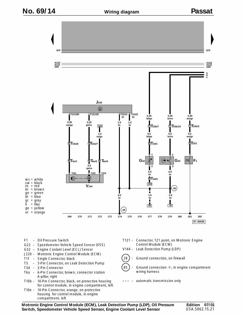
97--30038
87F
T121/1
br1,5
J220
31T121/2
br1,5
31
85
169 170 171 172 173 174 175 176 177 178 179 180 181 182
T3/1 T3/3T3/2
T10e/6
T6o/1
T10e/7
T6o/2
ge/ro0,5
T121/80
0,35
T121/25
ge/ro0,35
160
ro/gn1,5
V144
M
T6o/5 G32
1
2
0,5br
T10b/7
0,5bl/ge
0,35bl/ge
T3d/1
T3d/3
190
T10b/10
0,5br/ro
0,5br
0,35br/ro
G22
2
3
T
0,5ws/gr
0,35ws/gr
T
10b/3
F1
1f/1
A122A121A60
A122A121A60
45
1,5br
16
2,5br
4,0br
28
ws/ge
a
cb
Edition 07/01USA.5062.15.21
Wiring diagram
ws = whitesw = blackro = redbr = browngn = greenbl = bluegr = greyli = lilacge = yellowor = orange
Motronic Engine Control Module (ECM), Leak Detection Pump (LDP), Oil PressureSwitch, Speedometer Vehicle Speed Sensor, Engine Coolant Level Sensor
No. 69/14 Passat
F1 - Oil Pressure SwitchG22 - Speedometer Vehicle Speed Sensor (VSS)G32 - Engine Coolant Level (ECL) SensorJ220 - Motronic Engine Control Module (ECM)T1f - Single Connector, blackT3 - 3-Pin Connector, on Leak Detection PumpT3d - 3-Pin ConnectorT6o - 6-Pin Connector, brown, connector station
A-pillar, rightT10b - 10-Pin Connector, black, on protective housing
for control module, in engine compartment, leftT10e - 10-Pin Connector, orange, on protective
housing for control module, in enginecompartment, left
T121 - Connector, 121 point, on Motronic EngineControl Module (ECM)
V144 - Leak Detection Pump (LDP)
28 - Ground connection, on firewall
85 - Ground connection -1-, in engine compartmentwiring harness
- - - - automatic transmission only
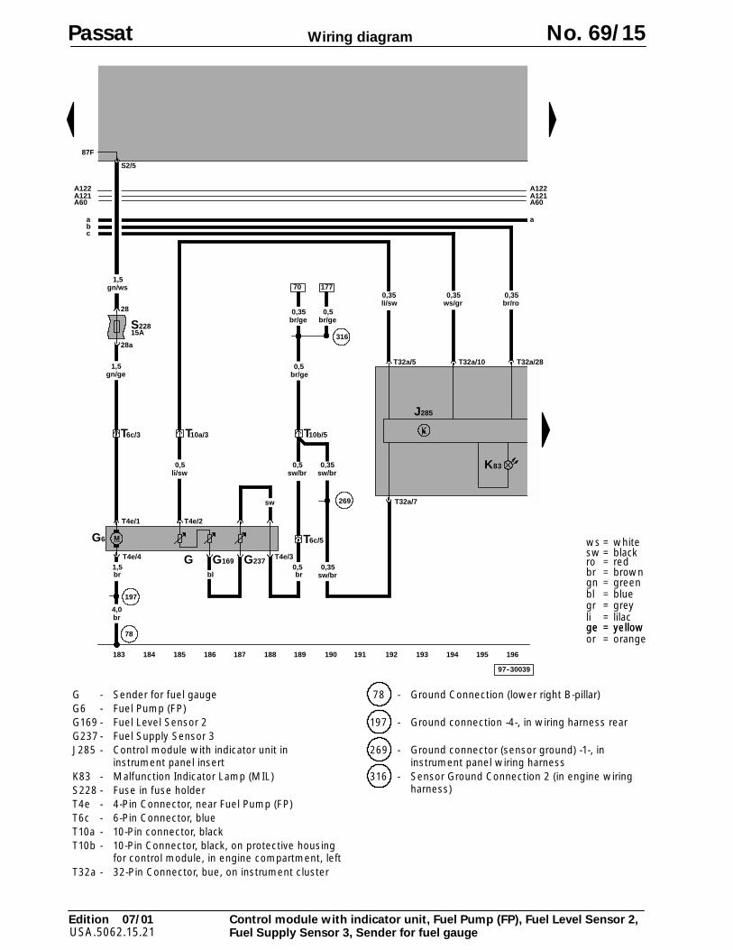
97--30039
87F
187 188 189 190 191 192 193 194 195 196183 184 185 186
T4e/1 T4e/2
T4e/4 T4e/3
M
197
S22815A
28
28a
S2/5
gn/ge1,5
T6c/3 T10a/3
li/sw0,5
T6c/5
br0,5
sw/br0,5
br1,5
br4,0
78
T10b/5
269
sw/br0,35
70
br/ge0,35
G169G G237
sw
bl
G6
316
gn/ws1,5
177
br/ge0,5
sw/br0,35
ws/gr0,35
T32a/10
T32a/7
T32a/5
0,35li/sw
T32a/28
br/ro0,35
br/ge0,5
J285
A121A122
A60
abc
K83
A121A122
A60
a
Edition 07/01USA.5062.15.21
Wiring diagram
ws = whitesw = blackro = redbr = browngn = greenbl = bluegr = greyli = lilacge = yellowge = yellowor = orange
Control module with indicator unit, Fuel Pump (FP), Fuel Level Sensor 2,Fuel Supply Sensor 3, Sender for fuel gauge
Passat No. 69/15
G - Sender for fuel gaugeG6 - Fuel Pump (FP)G169 - Fuel Level Sensor 2G237 - Fuel Supply Sensor 3J285 - Control module with indicator unit in
instrument panel insertK83 - Malfunction Indicator Lamp (MIL)S228 - Fuse in fuse holderT4e - 4-Pin Connector, near Fuel Pump (FP)T6c - 6-Pin Connector, blueT10a - 10-Pin connector, blackT10b - 10-Pin Connector, black, on protective housing
for control module, in engine compartment, leftT32a - 32-Pin Connector, bue, on instrument cluster
78 - Ground Connection (lower right B-pillar)
197 - Ground connection -4-, in wiring harness rear
269 - Ground connector (sensor ground) -1-, ininstrument panel wiring harness
316 - Sensor Ground Connection 2 (in engine wiringharness)
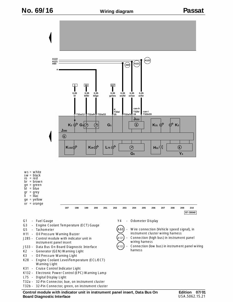
97--30040
197 198 199 200 201 202 203 204 205 206 207 208 209 210
G1G3
J285
H11
Y4G5
T32b/19 T32b/20
K28
K2
T32a/22T32a/8
68 107
gn/ws0,35
ws/bl0,35
or/br0,35
or/sw0,35
T32a/3
bl/ge0,35
bl/br0,35
3
L75
T32a/25
K
A121A122
A60
T32a/12
K3
bl0,35
can-lcan-h
K31
K132
J533
A121A122
A60
a
Edition 07/01USA.5062.15.21
Wiring diagram
ws = whitesw = blackro = redbr = browngn = greenbl = bluegr = greyli = lilacge = yellowor = orange
Control module with indicator unit in instrument panel insert, Data Bus OnBoard Diagnostic Interface
No. 69/16 Passat
G1 - Fuel GaugeG3 - Engine Coolant Temperature (ECT) GaugeG5 - TachometerH11 - Oil Pressure Warning BuzzerJ285 - Control module with indicator unit in
instrument panel insertJ533 - Data Bus On Board Diagnostic InterfaceK2 - Generator (GEN) Warning LightK3 - Oil Pressure Warning LightK28 - Engine Coolant Level/Temperature (ECL/ECT)
Warning LightK31 - Cruise Control Indicator LightK132 - Electronic Power Control (EPC) Warning LampL75 - Digital Display LightT32a - 32-Pin Connector, bue, on instrument clusterT32b - 32-Pin Connector, green, on instrument cluster
Y4 - Odometer Display
A60 - Wire connection (Vehicle speed signal), ininstrument cluster wiring harness
A121 - Connection (high bus) in instrument panelwiring harness
A122 - Connection (low bus) in instrument panel wiringharness