Embed Size (px)
Citation preview
NASA-STD-7001National Aeronautics and JUNE 21, 1996Space Administration
PAYLOADVIBROACOUSTICTEST CRITERIA
NASA TECHNICAL STANDARD
NOT MEASUREMENTSENSITIVE

NASA-STD-7001June 21, 1996
i
FOREWORD
This standard is approved for use by NASA Headquarters and all Field Centers and isdesigned to provide a common framework for consistent practices across NASA programs.
In early 1993, a concerted effort was initiated within the NASA engineering community todevelop Agency-wide standards for hardware verification in four disciplines: fracture control,loads definition, vibroacoustics, and ground support equipment. These efforts resulted from arecommendation of the NASA Engineering Management Council (EMC), which hadencouraged a similar activity in 1992 for structural factors of safety. That activity produced awhite paper on factors of safety for the EMC that was well received and led to the expansion ofthe effort to the other four disciplines.
The exchange of flight hardware in multicenter projects mandates that qualification andacceptance test practices be consistent across the Agency. Recent experience in these kindsof projects, where different field installation policies are invoked, has necessitated case-by-case negotiations on testing requirements and special evaluations of qualification status. Thisapproach may result in technical compromises and certainly incurs unnecessary costs anddelays in project progress. The goal of a single NASA policy for vibroacoustics verification testpractices will do much to streamline the intercenter research and development process.
The Vibroacoustics Standards Panel was assembled by the Goddard Space Flight Center(GSFC), which was named to chair and organize the activity. Members were nominated byEMC representatives of the Centers and guidance to the Panel by the EMC was broad andnon-specific. Essentially, the EMC expected the Panel to develop and execute a charter thatwould serve as a directive to generate guidelines for the development of a standardsdocument that would address the long standing divergence of practices within the Agencyregarding the vibroacoustic qualification and acceptance testing of payload hardware. As aresult, the Panel produced a white paper that contains a resolution of the divergent issues andthe necessary core information to develop the subject standards document.
Requests for information, corrections, or additions to this standard should be directed to theStructures and Dynamics Laboratory, Mail Code ED21, Marshall Space Flight Center, AL,35812. Requests for additional copies of this standard should be sent to NASA EngineeringStandards, EL02, MSFC, AL 35812 (telephone 205-544-2448).
Daniel R. MulvilleChief Engineer
NASA-STD-7001June 21, 1996
ii
CONTENTS
PARAGRAPH PAGE
FOREWORD ............................................................................................. i
TABLE OF CONTENTS............................................................................. ii
LIST OF FIGURES, TABLES, AND APPENDICES ................................... iii
1. SCOPE...................................................................................................... 11.1 Scope................................................................................................ 11.2 Purpose ............................................................................................ 11.3 Applicability ....................................................................................... 11.4 Summary of verification test requirements ........................................ 2
2. APPLICABLE DOCUMENTS..................................................................... 22.1 General ............................................................................................. 22.2 Government documents.................................................................... 22.3 Non-Government publications........................................................... 32.4 Order of precedence......................................................................... 4
3. DEFINITIONS ............................................................................................ 4
4. REQUIREMENTS ...................................................................................... 44.1 Methods and assumptions related to use of verification
tests .................................................................................................. 44.1.1 Purpose of tests and test factors ...................................................... 44.2 Test levels......................................................................................... 54.2.1 Prototype and protoflight................................................................... 54.2.2 Acceptance testing............................................................................ 54.2.3 Workmanship.................................................................................... 54.2.4 Acoustic fill effect .............................................................................. 64.3 Test methods and specifications....................................................... 84.3.1 Acoustic tests.................................................................................... 84.3.2 Random vibration tests ..................................................................... 94.3.3 Test duration..................................................................................... 104.3.4 Test control tolerances...................................................................... 114.3.5 Test configuration ............................................................................. 114.3.6 Test tailoring methods....................................................................... 124.4 Dynamic data acquisition and analysis ............................................. 13
5. NOTES ...................................................................................................... 135.1 Intended use ..................................................................................... 135.2 Subject term (key word) listing .......................................................... 135.3 Abbreviations and acronyms............................................................. 14
NASA-STD-7001June 21, 1996
iii
FIGURES
FIGURE PAGE
1. Fill Factor Design Chart ............................................................................. 8
TABLES
TABLE PAGE
I. Component Minimum Workmanship Random Vibration Test Levels ......... 6
APPENDICES
APPENDIX PAGE
A Methods for Vibroacoustic Analyses.......................................................... 15B Vibroacoustic Load Prediction ................................................................... 18

NASA-STD-7001June 21, 1996
1
PAYLOAD VIBROACOUSTIC TEST CRITERIA
1. SCOPE
1.1 Scope. The term vibroacoustics is defined as an environment induced by high-intensity acoustic noise associated with various segments of the flight profile. It manifestsitself throughout the payload in the form of transmitted acoustic excitation and as structure-borne random vibration. Therefore, the standard is to specifically address the acoustic andrandom vibration environments and test levels.
1.2 Purpose. The primary objective of this standard is to establish a uniform usage oftest factors in the vibroacoustic verification process for spaceflight payload hardware. Thestandard provides test factors for verification of payload hardware for prototype, protoflight,and flight acceptance programs. In addition, minimum workmanship test levels are included.With the exception of minimum workmanship test levels, the test levels are given in relation tothe "maximum expected flight level” (MEFL). Although the major emphasis of the standard ison test levels, the standard also covers the subjects of test duration, test control tolerances,data analysis, test tailoring, payload fill effects, and analysis methods.
1.3 Applicability. This standard recommends engineering practices for NASA programsand projects. It may be cited in contracts and program documents as a technical requirementor as a reference for guidance. Determining the suitability of this standard and its provisions isthe responsibility of program/project management and the performing organization. Individualprovisions of this standard may be tailored (i.e., modified or deleted) by contract or programspecifications to meet specific program/project needs and constraints.
The standard applies only to spaceflight payload hardware. Launch vehicles, payloadslaunched by sounding rockets, aircraft and balloons, and ground support equipment areexcluded. The levels of assembly for which the standard is applicable are the payload,subsystem, and component levels as specifically identified or as judged to be appropriate. Apayload is defined as an assemblage of subsystems designed to perform a specified missionin space; a subsystem is defined as a functional subdivision of a payload consisting of two ormore components; and a component is defined as a functional subdivision of a subsystem andis generally a self-contained combination of items performing a function necessary for thesubsystem's operation. The standard is applicable to the full range of payload hardwareprograms including prototype, protoflight, follow-on, spare, and reflight.
The levels and methods set forth herein shall form the basis for developing project-specificrequirements for all new payload projects. Deviations to and tailoring of the standard for theproject's specific applications shall be reviewed and approved by the project manager and theappropriate engineering support organization. As much as possible, these variances shall beidentified early in the project's life cycle, e.g., prior to phase C/D implementation. A permanentrecord shall be maintained by the project's quality assurance organization. The standard shallbe applicable principally to Class A, B, and C payloads, while Class D payloads may utilizetailoring as stated in 4.3.6.
NASA-STD-7001June 21, 1996
2
1.4 Summary of verification test requirements.
Maximum expected flight level (MEFL) 95%/50% Probability Level
Test levelsPrototype/protoflight qualification MEFL + 3 dBFlight acceptance MEFL - 3 dBMinimum vibration workmanship test 6.8 grmsMinimum acoustic workmanship test 138 dB
Test durationsPrototype qualification, single mission 2 minutesPrototype qualification, multiple (N) reflights 2 + 0.5N minutesProtoflight qualification 1 minuteFlight acceptance 1 minutePayload classification applicability Classes A, B, and C
A minimum workmanship random vibration test specification shall be imposed on electrical,electronic, and electromechanical components weighing less than 50 kilograms (kg) (110 lb.). Thespectrum is given in 4.2.3, Table I. When the workmanship test level exceeds the prototype/protoflight and/or the flight acceptance levels, the test levels shall envelope the two spectra.
Random vibration test control tolerances on power spectral densities (PSD's) shall be ±3 decibels(dB). When the minimum workmanship test level governs in a prototype program, the tolerancesshall be such that the acceptance test level never exceeds the qualification test level. Thetolerance on composite root mean square (rms) accelerations shall be ±10 percent.
Acoustic test control tolerances on sound pressure levels (SPL's) shall be ±3 dB from 50 to 3000hertz (Hz), with facility capability determining the tolerances below 50 Hz and above 3000 Hz.The tolerance on overall SPL's shall be ±1 dB.
2. APPLICABLE DOCUMENTS
2.1 General. The applicable documents cited in this standard are listed in this sectiononly for reference. The specified technical requirements listed in the body of this documentmust be met whether or not the source document is listed in this section.
2.2 Government documents. The following Government documents form a part of thisdocument to the extent specified herein. Unless otherwise specified, the issuances in effecton date of invitation for bids or request for proposals shall apply.
NASA-CR-173472 - NASA Flight Electronics Environmental StressScreening Survey, E.J. Marian, Washington, DC,December 1983
NASA TN-2158 - Statistical Techniques for Describing LocalizedVibratory Environments of Rocket Vehicles,Robert E. Barrett
NASA-STD-5002 - Load Analyses of Spacecraft and Payloads
NASA-STD-7001June 21, 1996
3
(Unless otherwise indicated, copies of the above documents are available from anyNASA Installation library or documentation repository.)
2.3 Non-Government publications. The following documents form a part of thisdocument to the extent specified herein. Unless otherwise specified, the issuances in effecton the date of invitation for bids or request for proposals shall apply.
Report No. 99S0650 - Test Report for Acoustic and Structural Response TestTest of Generic Spacecraft/Nose Fairing Configurations,M.A. Gehringer, B.H. Forssen, General Dynamics Space Systems Division, June 1, 1994
- NASA LeRC’s Acoustic Fill Effect Test Programand Results, W.O. Hughes and M.E. McNelis,NASA Lewis Research Center, J.E. Manning,Cambridge Collaborative Incorporated,Proceedings of the 15th Aerospace TestingSeminar, October 11-13, 1994
CC Report 93-11-12349-01 - Acoustic Fill Factor Report, J.E. Manning, B.F.Hebert, K. Weissman, Cambridge CollaborativeIncorporated, submitted to NASA LewisResearch Center, November 30, 1993
CC Report 91-6-12104-1 - Analysis and Evaluation of the Fill Factor, J.E.Manning, Cambridge Collaborative Incorporated,submitted to NASA Lewis Research Center,January 28, 1991
- Force Specifications for Extremal Dual ControlledVibration Tests, Terry Scharton, 61st Shock andVibration Symposium, Los Angeles, CA, October 1990
- Development of the Force Envelope for anAcceleration/Force Extremal Controlled VibrationTest, D. Smallwood, 61st Shock and VibrationSymposium, Los Angeles, CA, October 1990
- Force Limited Vibration Testing at JPL, Terry Scharton,IES/Aerospace Corporation, 14th Aerospace TestingSeminar, Manhattan Beach, CA, March 1993
- Vibration Test Force Limits Derived From FrequencyShift Method, Terry Scharton, AIAA 35th Structures,Structural Dynamics, and Materials Conference, HiltonHead, SC, April 18-20, 1994
IES-RP-DTE012.1 - Handbook for Dynamic Data Acquisition andAnalysis, Institute of Environmental Sciences
NASA-STD-7001June 21, 1996
4
Sandia Monograph SCR-607 - Factors for One-Sided Tolerance Limits and forVariables Sampling Plans, D.B. Owen, March 1963
- Statistics of Extremes, E.J. Gumbel, ColumbiaUniversity Press, 1958
- Structural Acoustics Using Statistical EnergyAnalysis, presented by J.E. Manning, CambridgeCollaborative Incorporated, at NASA LewisResearch Center, November 7, 1988
- Statistical Energy Analysis of DynamicalSystems: Theory and Applications, by R.H.Lyon, MIT Press, Cambridge, MA, 1975
(Unless otherwise indicated, copies of the above documents are available from anyNASA Installation library or documentation repository.)
2.4 Order of precedence. Where this document is adopted or imposed by contract on aprogram or project, the technical guidelines of this document take precedence, in the case ofconflict, over the technical guidelines cited in other referenced documents. This standard doesnot apply to payload programs approved prior to the date of this document. Also, this standarddoes not address safety considerations that are covered thoroughly in other documents; but ifa conflict arises, safety shall always take precedence. Nothing in this document, however,supersedes applicable laws and regulations unless a specific exemption has been obtained.
3. DEFINITIONS
None (Abbreviations and Acronyms are found in 5.3.)
4. REQUIREMENTS
4.1 Methods and assumptions related to use of verification tests.
4.1.1 Purpose of tests and test factors. The purpose of testing with test factors is toprove design performance at the MEFL, plus margin for uncertainty, to demonstrate thathardware is acceptable for flight, and to verify that adequate workmanship exists in theconstruction of the hardware. Tests are critical for high frequency sensitive equipmentbecause the complexity of design details of such hardware seriously limits the use of analysis.Also, tests are not intended to produce loads that exceed design requirements or to introduceunrealistic modes of failure. When defining test factors, various sources of uncertainty mustbe considered such as the following:
a. Material properties variations (strength and life)
b. Fabrication, variations (within specification)
c. Load variations
d. Test configuration fidelity
NASA-STD-7001June 21, 1996
5
e. Environment specification method fidelity
f. Design maturity uncertainty
g. Cost, schedule, and risk
4.2 Test levels.
4.2.1 Prototype and protoflight.
a. Prototype tests, also referred to as qualification tests, are performed on dedicated testhardware which is produced from the same drawings and using the same materials, tooling,manufacturing processes, inspection methods, and level of personnel competency as used forthe flight hardware. Prototype tests demonstrate, with margin, the design adequacy of thehardware for its intended mission use.
b. Protoflight tests are performed on flight and flight spare hardware where dedicatedtest hardware for prototype testing does not exist. The protoflight testing of flight spares wouldoccur only when the first item built is declared to be a spare. Protoflight tests serve thepurpose of both the prototype and flight acceptance tests. That is, the tests assess the designadequacy of the hardware, demonstrate the satisfactory performance of the flight hardwarerelative to the expected environment, and reveal inadequacies in workmanship and materialintegrity.
c. Acoustic prototype and protoflight tests shall be conducted at levels that are anenvelope of the maximum expected flight level plus 3 dB and the minimum workmanship levelsdefined in 4.2.3. Random vibration prototype and protoflight tests shall be conducted at levelsthat envelope the maximum expected flight level plus 3 dB and the minimum workmanshiplevels as defined in Table I, 4.2.3. Methods for determining the maximum expected flight levelare described in 4.4.
4.2.2 Acceptance testing. Acceptance tests are conducted to demonstrate satisfactoryperformance of flight systems relative to the expected environment and to reveal inadequaciesin workmanship and material integrity. The tests are performed for hardware that has beenqualified by prototype or protoflight testing. Flight acceptance units include follow-onspacecraft hardware and flight spares that are identical in design and material configuration tothe qualified article.
Acoustic flight unit acceptance tests are conducted at levels that are an envelope of themaximum expected flight level minus 3 dB and the minimum acoustic test spectrum defined in4.2.3. Random vibration flight unit acceptance tests are conducted at levels that envelope themaximum expected flight level minus 3 dB and the minimum workmanship levels as defined inTable I, 4.2.3.
4.2.3 Workmanship. Workmanship random vibration testing is performed to identifylatent defects and manufacturing flaws in electrical, electronic, and electromechanicalhardware at the component level. Care should be exercised not to apply these criteria,however, to highly sensitive optical components and sensors that could be damaged by thestated levels.
NASA-STD-7001June 21, 1996
6
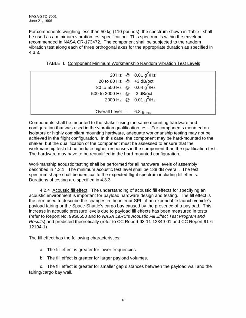
For components weighing less than 50 kg (110 pounds), the spectrum shown in Table I shallbe used as a minimum vibration test specification. This spectrum is within the enveloperecommended in NASA CR-173472. The component shall be subjected to the randomvibration test along each of three orthogonal axes for the appropriate duration as specified in4.3.3.
TABLE I. Component Minimum Workmanship Random Vibration Test Levels
20 Hz @ 0.01 g2/Hz20 to 80 Hz @ +3 dB/oct
80 to 500 Hz @ 0.04 g2/Hz500 to 2000 Hz @ -3 dB/oct
2000 Hz @ 0.01 g2/Hz
Overall Level = 6.8 grms
Components shall be mounted to the shaker using the same mounting hardware andconfiguration that was used in the vibration qualification test. For components mounted onisolators or highly compliant mounting hardware, adequate workmanship testing may not beachieved in the flight configuration. In this case, the component may be hard-mounted to theshaker, but the qualification of the component must be assessed to ensure that theworkmanship test did not induce higher responses in the component than the qualification test.The hardware may have to be requalified in the hard-mounted configuration.
Workmanship acoustic testing shall be performed for all hardware levels of assemblydescribed in 4.3.1. The minimum acoustic test level shall be 138 dB overall. The testspectrum shape shall be identical to the expected flight spectrum including fill effects.Durations of testing are specified in 4.3.3.
4.2.4 Acoustic fill effect. The understanding of acoustic fill effects for specifying anacoustic environment is important for payload hardware design and testing. The fill effect isthe term used to describe the changes in the interior SPL of an expendable launch vehicle'spayload fairing or the Space Shuttle's cargo bay caused by the presence of a payload. Thisincrease in acoustic pressure levels due to payload fill effects has been measured in tests(refer to Report No. 99S0650 and to NASA LeRC’s Acoustic Fill Effect Test Program andResults) and predicted theoretically (refer to CC Report 93-11-12349-01 and CC Report 91-6-12104-1).
The fill effect has the following characteristics:
a. The fill effect is greater for lower frequencies.
b. The fill effect is greater for larger payload volumes.
c. The fill effect is greater for smaller gap distances between the payload wall and thefairing/cargo bay wall.
NASA-STD-7001June 21, 1996
7
The acoustic fill effect shall be implemented as follows:
1. Calculate the payload volume, Volpayload, in a zone of interest.
2. Calculate the empty fairing/cargo bay volume (with the same length as the payloadzone), Volempty.
3. Use the results of steps 1 and 2 to calculate the ratio of the payload volume to theempty fairing/cargo bay volume, Volratio.
VolVol
Volratiopayload
empty
=
4. Calculate an average gap distance (Hgap) between the payload surface and thefairing/cargo bay surface.
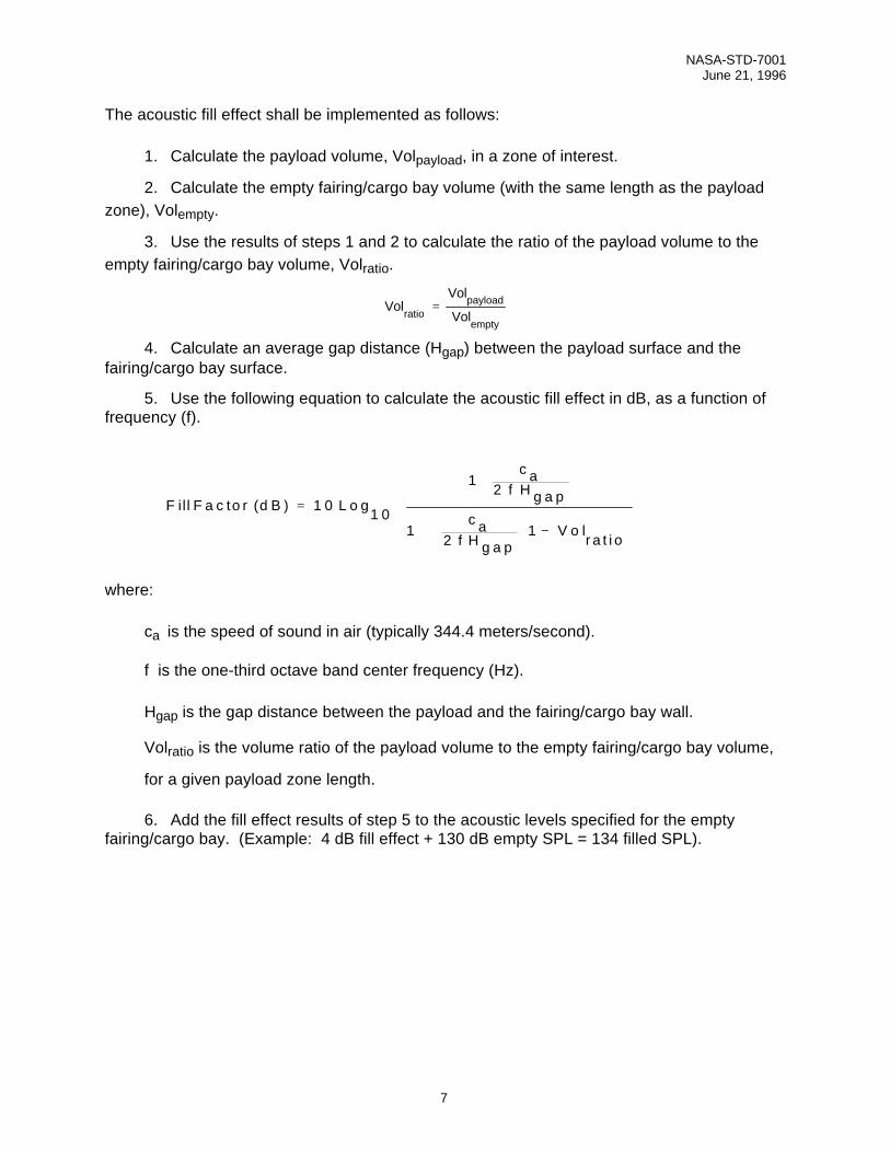
5. Use the following equation to calculate the acoustic fill effect in dB, as a function offrequency (f).
F ill F a c to r d B L o g
c af H g a p
c af H g a p
V o lr a t i o
( ) =
+
+ −
1 01 0
12
12
1
where:
ca is the speed of sound in air (typically 344.4 meters/second).
f is the one-third octave band center frequency (Hz).
Hgap is the gap distance between the payload and the fairing/cargo bay wall.
Volratio is the volume ratio of the payload volume to the empty fairing/cargo bay volume,
for a given payload zone length.
6. Add the fill effect results of step 5 to the acoustic levels specified for the emptyfairing/cargo bay. (Example: 4 dB fill effect + 130 dB empty SPL = 134 filled SPL).
NASA-STD-7001June 21, 1996
8
0
1
2
3
4
5
6
7
8
9
10
0.001 0.01 0.1 1 10
Dimensionless Frequency (f Hgap / ca)
Incr
ease
Due
to F
ill E
ffect
, dB
90%
80%
70%
60%
50%
40%
30%20%10%
% Volume Fill
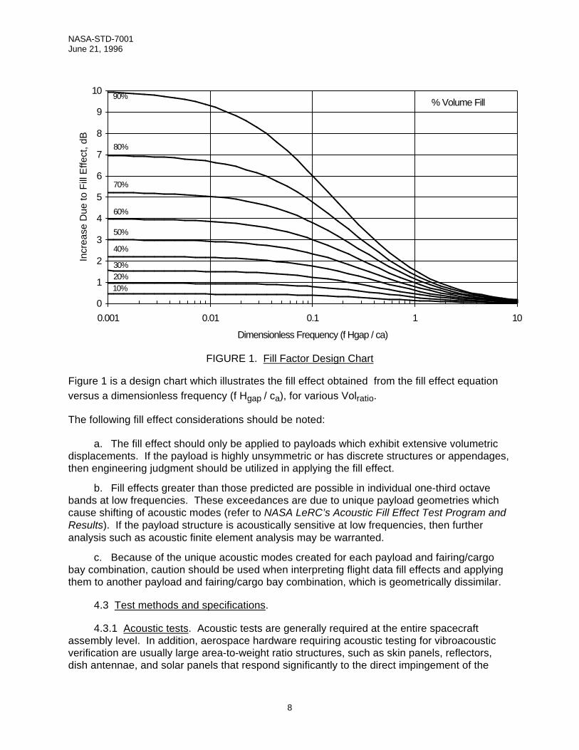
FIGURE 1. Fill Factor Design Chart
Figure 1 is a design chart which illustrates the fill effect obtained from the fill effect equationversus a dimensionless frequency (f Hgap / ca), for various Volratio.
The following fill effect considerations should be noted:
a. The fill effect should only be applied to payloads which exhibit extensive volumetricdisplacements. If the payload is highly unsymmetric or has discrete structures or appendages,then engineering judgment should be utilized in applying the fill effect.
b. Fill effects greater than those predicted are possible in individual one-third octavebands at low frequencies. These exceedances are due to unique payload geometries whichcause shifting of acoustic modes (refer to NASA LeRC’s Acoustic Fill Effect Test Program andResults). If the payload structure is acoustically sensitive at low frequencies, then furtheranalysis such as acoustic finite element analysis may be warranted.
c. Because of the unique acoustic modes created for each payload and fairing/cargobay combination, caution should be used when interpreting flight data fill effects and applyingthem to another payload and fairing/cargo bay combination, which is geometrically dissimilar.
4.3 Test methods and specifications.
4.3.1 Acoustic tests. Acoustic tests are generally required at the entire spacecraftassembly level. In addition, aerospace hardware requiring acoustic testing for vibroacousticverification are usually large area-to-weight ratio structures, such as skin panels, reflectors,dish antennae, and solar panels that respond significantly to the direct impingement of the
NASA-STD-7001June 21, 1996
9
acoustic environment. Two types of components require both vibration and acoustic testing:(1) those components which are mounted with vibration isolators, and (2) those componentswhich consist of significant piece parts with first resonant frequencies greater than 2000 Hz.Vibration isolators attenuate the high frequency mechanical vibration below the level resultingfrom direct acoustic impingement; therefore, these components should be reviewed on a case-by-case basis, and a test program should be implemented that also satisfies minimumworkmanship criteria. Also, many electronic black boxes and glass components havemicrostructural elements that are resonant above 2000 Hz, which is generally the limitation ofmost large electrodynamic shakers. Acoustic testing shall be performed by controlling theSPL’s (dB re 20 µPa) in 1/3-octave bands over the specified frequency range.
All payload structures and components requiring acoustic testing shall be subjected tobroadband reverberant field testing. The acoustical random noise source shall have anapproximate normal amplitude distribution. Test levels shall be determined using the methodsdescribed in 4.2.1 and 4.2.2, and the test tolerances to be adhered to are described in 4.3.4.
The reverberant field test chamber shall be of sufficient volume and dimensions to ensure thatthe insertion of a test specimen will not affect the generation and maintenance of a broadbanddiffuse sound field above 50 Hz. It is preferable that the chamber volume be at least 10 timesthe test specimen volume. If the test specimen is to be suspended, the suspension systemshould have a fundamental frequency of less than 25 Hz. The sound field in the proximity ofeach major surface of any test specimen that will be subjected to acoustic environments shallbe determined by at least three microphones. The microphones shall be positioned around thetest chamber at sufficient distance from all surfaces to avoid absorption and re-radiationeffects. A distance from any surface of at least 1/4 of the wavelength of the lowest frequencyof interest is recommended. In facilities where this cannot be achieved, the microphones shallbe located in positions so as to be affected as little as possible by surface effects. The controlmeasurements shall be averaged to determine the sound field.
With the specimen in the test chamber, the acoustic spectrum shall be shaped at a levelapproximately 6 dB less than the specification. The time required to shape the spectrum shallbe minimized to avoid possible fatigue of the test specimen. After completion of the spectrumshaping, the SPL shall be increased to the specified value, and the test will then commence.As an alternative to reducing the SPL while shaping the spectrum, a dummy specimen may bepositioned in the test chamber and the spectrum shaped at the test level. When the spectrumshaping has been completed, the dummy specimen shall be replaced by the test specimen,and the test will then begin.
4.3.2 Random vibration tests. Random vibration testing is required for essentially allelectrical, electronic, and electromechanical components and mechanisms. Exceptions arelarge area-to-weight structures, which may be subjected to acoustic testing in lieu of randomvibration, and hardware not practical to vibrate at the component level such as structures,electrical cabling, plumbing lines, blankets, etc., that may be deferred to the system levelvibration or acoustic test. Compact payloads weighing less than 450 kg (1000 pounds) shallbe subjected to system level random vibration testing unless an analysis shows that thepayload responses are clearly dominated by the direct acoustic environment.
The test specimen shall be subjected to random vibration with a Gaussian amplitudedistribution in each of three orthogonal axes. Random vibration testing shall be performed by
NASA-STD-7001June 21, 1996
10
controlling the acceleration spectral density (g2/Hz) in the frequency range from 20 to 2000 Hz.The spectrum shall be within the test tolerance specified in 4.3.4.
The control accelerometer(s) shall be mounted on the test fixture near the attachment points. Ifmore than one control accelerometer is used, the test levels may be controlled using either anaveraging or an extremal control scheme; but the controller must be consistent with the testrequirement derivation. The test fixture shall be subjected to a bare resonance survey up to2000 Hz prior to the start of testing. If practical, the fixture shall have no resonances within thetest frequency range. The test specimen shall be mounted to the fixture via its flight or flightequivalent mounting attachments.
Notching of the acceleration spectral density input may be technically justified in certain casesto eliminate unrealistically high amplification resonant responses and the associated risk offailures which can occur in conventional vibration tests of aerospace hardware. For typicalaerospace structures, the mechanical impedance of the test item and the flight mountingstructure are comparable so that the combined motion involves modest interface forces andlittle amplification. However, the mounting of the test item on a vibration fixture, with aneffectively infinite impedance compared to the test item, results in high interface forces andoften severely overtests the hardware at its resonances. This test artifact can be eliminated bylimiting the interface forces in the test to that predicted for flight.
Force limiting provides a rational and economical solution to the overtesting problemassociated with hard mounting of test items, while still providing high confidence in thecapability of the hardware to survive the mission vibroacoustic environments. The theory andmethodology for implementing force limiting, along with examples of specific applications, arepresented in the following applicable Government documents:
Force Specifications for Extremal Dual Controlled Vibration Tests
Development of the Force Envelope for an Acceleration/Force Extremal ControlledVibration Test
Force Limited Vibration Testing at JPL
Vibration Test Force Limits Derived from Frequency Shift Method.
4.3.3 Test duration. The durations for the tests described in 4.3.1 (acoustic tests) and4.3.2 (random vibration tests) shall be as defined in the following paragraphs:
a. Qualification test duration.
1) Prototype. The prototype vibroacoustic qualification test durations shall be 2minutes for the acoustic test and 2 minutes in each of the three orthogonal axes for thevibration test. If the flight hardware is to be reflown N times, the corresponding qualificationtest durations shall be 2 + 0.5N minutes.
2) Protoflight. The protoflight vibroacoustic qualification test durations shall be 1minute for an acoustic test and 1 minute in each of the three orthogonal axes for a vibrationtest.
NASA-STD-7001June 21, 1996
11
b. Acceptance test duration.
1) Prototype program. The vibroacoustic acceptance test durations, for a flight unitdeveloped under the prototype concept, shall be 1 minute for an acoustic test and 1 minute ineach of the three orthogonal axes for a vibration test.
2) Protoflight program. For follow-on spacecraft hardware and spares, the acceptancetest durations shall be 1 minute for an acoustic test and 1 minute in each of the three orthogonalaxes for a vibration test. There can be other situations (e.g., retesting of reflight hardware)where the test conditions will be defined by applying test tailoring (see 4.3.6).
4.3.4 Test control tolerances. For prototype program qualification and acceptancetesting, the test control tolerances shall be such that the acceptance test level shall neverexceed the qualification test level. The restricted use of tolerances is particularly critical whenthe minimum workmanship random vibration or acoustic specification governs any portion ofthe enveloped spectrum. With this stated condition, acceptable tolerances are as follows:
a. Vibration.
1) Composite RMS acceleration.................................................±10%
2) Acceleration spectral density (25 Hz or less frequencybandwidth resolution) ..............................................................±5%
3) Frequency ................................................................................±5%
4) Test duration ..........................................................................+10%, -0%
b. Acoustic.
1) Individual 1/3 octave band SPL’s(50 to 3000 Hz) ...................................................................... ±3 dB
2) Overall sound pressure level.................................................. ±1 dB
3) Test duration ................................................................. +10%, -0%
4) Facility capability will determine SPL tolerances below 50 Hz andabove 3000 Hz.
4.3.5 Test configuration. A satisfactory verification test program shall adhere to thefollowing test configuration methods:
a. During testing, the mechanical configuration of the test item shall be in a liftoffoperational mode. The electrical operating mode shall be in accordance with the test plan. Asa minimum requirement, the liftoff electrical condition shall be applied and monitored. Cautionshould be exercised so that full electrical stimulation for diagnostic purposes does not inducean unrealistic and damaging condition when combined with vibroacoustic exposure.
NASA-STD-7001June 21, 1996
12
b. In mating the test article to the test fixture, a flight-type mounting (including vibrationisolators if part of the design) and fasteners shall be used.
c. Components that are normally sealed shall be pressurized during the test to theirprelaunch pressure.
d. For very large payloads, it may be impracticable (because of test facility limitations) toperform a random vibration test at the payload level of assembly. In that case, testing at thesubsystem level of assembly shall be assessed.
e. For very large components, random vibration tests may have to be supplemented orreplaced by an acoustic test due to test facility limitations.
f. The same test fixture should be used for both qualification and flight acceptance tests.
g. If the component level tests are not capable of inducing sufficient excitation to internalelectric, electronic, and electromechanical devices to provide adequate workmanshipverification, an environmental stress screening test program shall be conducted at lower levelsof assembly (e.g., down to the board level, if necessary).
h. Vibroacoustic testing shall precede thermal-vacuum testing.
4.3.6 Test tailoring methods. This standard serves as a baseline that provides enoughflexibility to allow tailoring to the needs of non-baseline situations. Nevertheless, allrequirements of the standard shall be evaluated for each spacecraft application, and anyspecified tailoring shall be accompanied by a statement of the technical rationale for thetailoring. For example, random vibration test "notching" would be permitted on a case-by-casebasis. That is, when it can be demonstrated that a specific hard-mounted shaker randomvibration test would produce unrealistically high loads and/or responses, notching would beallowed. The logic used to develop a specific notching rationale shall be validated. Notchingcan be of the form of "force limiting" as discussed in 4.3.2. In addition to notching, there areother possible considerations that could dictate the use of test tailoring. Some of thesepossible considerations are as follows:
a. Class D payloads
b. Retesting of reflight hardware
c. Retesting due to limited redesign or rework
d. Storage
e. Fatigue damage concerns
f. Acoustic testing with payload fairing
g. Vibration testing with simulated support structure
h. Certain fragile, one-time use items such as instrument detector elements and batteries
NASA-STD-7001June 21, 1996
13
4.4 Dynamic data acquisition and analysis. Methods are being published by the Instituteof Environmental Sciences (IES) as an IES recommended practices handbook titled,Handbook for Dynamic Data Acquisition and Analysis (refer to IES-RP-DTE012.1). Thisdocument shall be used as a guideline for vibroacoustics data acquisition and analysis.
In practice, the maximum expected environment shall be based on:
a. The use of actual flight data scaled, if necessary, for differences in structure andacoustic environment
b. Ground test data scaled if necessary
c. Analytical predictions
d. A combination of both analytical and empirical methods
The flight data may be from the current flight system or from other flight systems ifconfiguration variations are accounted for and properly scaled. A statistical approach shall notbe used unless at least three data points are available, and engineering experience must beused to account for data and analysis uncertainties. Methods for vibroacoustic analysis arediscussed in more detail in Appendix A.
Ground test operations and transportation vibroacoustic levels shall be controlled such thatlevels produced by these events shall not exceed the MEFL’s. If it is not practicable to soconstrain the ground test and/or transportation environments, they shall be considered ascontributing to the design and test criteria.
5. NOTES
(This section contains information of a general or explanatory nature which may behelpful but is not mandatory.)
5.1 Intended use. This standard defines procedures for developing vibroacoustic testcriteria for NASA payloads. It also presents methods for acceptance and qualificationvibroacoustic testing, for statistical analysis of vibroacoustic data, and analysis methods fordetermining criteria. Minimum acoustic and random vibration workmanship test levels arespecified. This standard only applies to NASA payloads and payload components and is notretroactive to the approval date.
5.2 Key word listing:
Acceptance testAcousticQualification testRandom vibrationVibrationVibroacoustic
NASA-STD-7001June 21, 1996
14
5.3 Abbreviations and acronyms
a. ca speed of sound in air
b. CF correction factor
c. dB decibel
d. EMC Engineering Management Council
e. f frequency
f. FEA Finite Element Analysis
g. g acceleration due to gravity
h. GSFC Goddard Space Flight Center
i. Hgap average gap distance
j. Hz hertz
k. IES Institute of Environmental Sciences
l. kg kilogram
m. MEFL maximum expected flight level
n. µPa micropascal
o. N number of reflights
p. OASPL overall sound pressure level
q. oct octave
r. PSD power spectral density
s. rms root mean square
t. SEA Statistical Energy Analysis
u. SPL sound pressure level
v. VAPEPS Vibroacoustic Payload Environmental Prediction System
w. Vol volume
NASA-STD-7001June 21, 1996
15
APPENDIX A
METHODS FOR VIBROACOUSTIC ANALYSES
A.1 DATA ANALYSIS
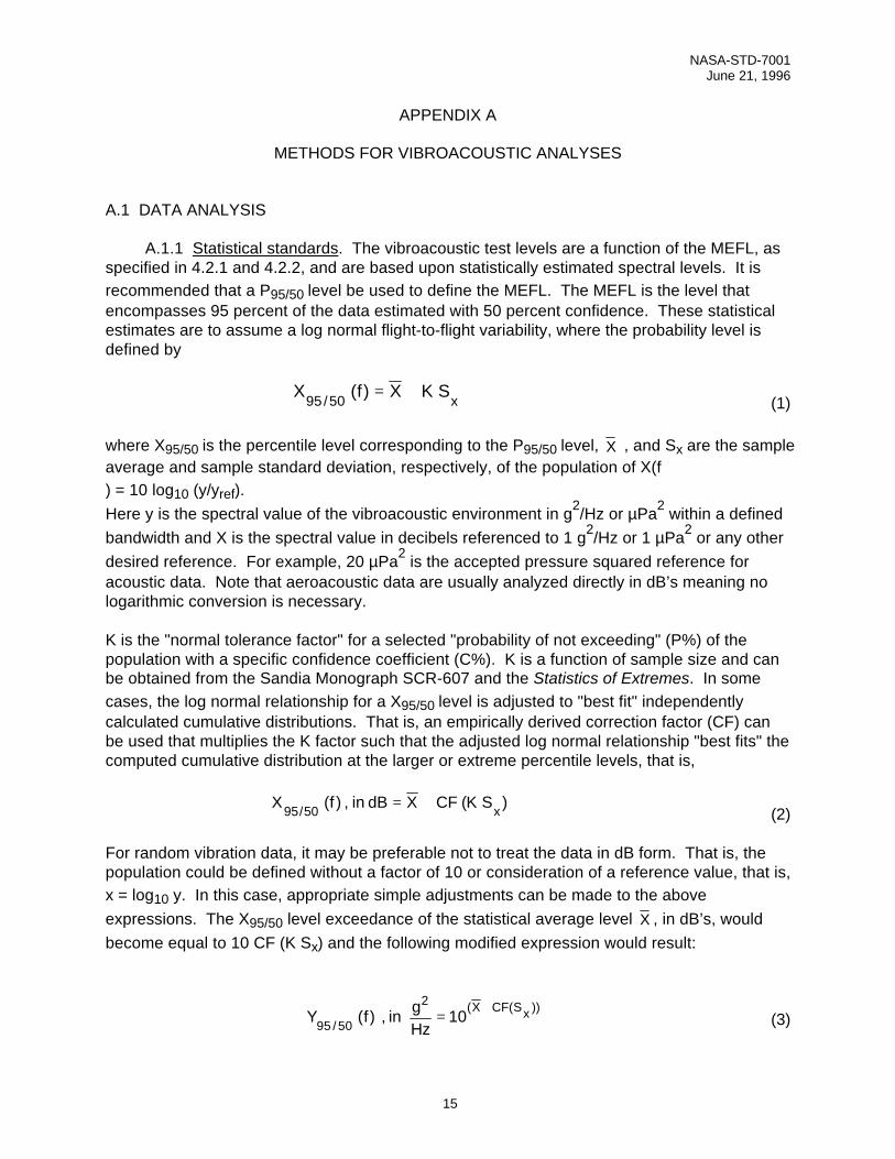
A.1.1 Statistical standards. The vibroacoustic test levels are a function of the MEFL, asspecified in 4.2.1 and 4.2.2, and are based upon statistically estimated spectral levels. It isrecommended that a P95/50 level be used to define the MEFL. The MEFL is the level thatencompasses 95 percent of the data estimated with 50 percent confidence. These statisticalestimates are to assume a log normal flight-to-flight variability, where the probability level isdefined by
X f X K Sx95 50/ ( ) = + (1)
where X95/50 is the percentile level corresponding to the P95/50 level, X , and Sx are the sampleaverage and sample standard deviation, respectively, of the population of X(f) = 10 log10 (y/yref).Here y is the spectral value of the vibroacoustic environment in g2/Hz or µPa2 within a definedbandwidth and X is the spectral value in decibels referenced to 1 g2/Hz or 1 µPa2 or any otherdesired reference. For example, 20 µPa2 is the accepted pressure squared reference foracoustic data. Note that aeroacoustic data are usually analyzed directly in dB’s meaning nologarithmic conversion is necessary.
K is the "normal tolerance factor" for a selected "probability of not exceeding" (P%) of thepopulation with a specific confidence coefficient (C%). K is a function of sample size and canbe obtained from the Sandia Monograph SCR-607 and the Statistics of Extremes. In somecases, the log normal relationship for a X95/50 level is adjusted to "best fit" independentlycalculated cumulative distributions. That is, an empirically derived correction factor (CF) canbe used that multiplies the K factor such that the adjusted log normal relationship "best fits" thecomputed cumulative distribution at the larger or extreme percentile levels, that is,
X f in dB X CF K Sx95 50/ ( ) , ( )= + (2)
For random vibration data, it may be preferable not to treat the data in dB form. That is, thepopulation could be defined without a factor of 10 or consideration of a reference value, that is,x = log10 y. In this case, appropriate simple adjustments can be made to the aboveexpressions. The X95/50 level exceedance of the statistical average level X , in dB’s, wouldbecome equal to 10 CF (K Sx) and the following modified expression would result:
Y f in gHz
X CF Sx95 50
210
/( ( ))
( ) , =+
(3)
NASA-STD-7001June 21, 1996
16
In this case, it must be recognized that the statistical terms X95/50, X , and Sx are computed for
a population defined as x = log10 y.
Even though a log normal distribution or modified form thereof was selected as the baselinedescriptor, based on the past experience of many investigators, this does not preclude the useof another distribution if it can be shown that it produces a satisfactory fit to the data (refer toNASA TN-2158).
In summary, the recommended procedure for statistical analysis is:
1. Calculate the common logarithm of the data (except for data already in dB form).
2. Calculate the mean and standard deviation of the logarithmic data.
3. Use the appropriate equation above to calculate the P95/50 level.
A.2 ANALYSIS METHODS
A.2.1 Statistical energy analysis. Statistical energy analysis (SEA) is a technique toanalyze and predict the vibroacoustic response of a complex system by calculating the energyflow between subsystems. Manning (refer to NASA TN-2158) describes SEA as follows:"Statistical: take a statistical approach toward the calculation of resonance frequencies andmode shapes; Energy: use vibratory energy and power flow to derive equations of motion;Analysis: maintain parameter dependence to allow for design changes and improvements."Manning (refer to Structural Acoustics Using Statistical Energy Analysis) further defines thekey SEA parameters to be: "modal density, damping loss factor, coupling loss factor andmechanical conductance." Further insight into SEA theory and applications may be found inStructural Acoustics Using Statistical Energy Analysis and Statistical Energy Analysis ofDynamical Systems: Theory and Applications.
SEA supplements the analyst's other tools such as empirical transfer functions (scaling) andfinite element techniques. SEA covers the medium to high frequency range (typically 100 Hzand higher), whereas finite element analysis is suited to lower frequencies. Although scalingtechniques may be accurate in the medium to high frequency range, a database of similarstructure is not always available. Additionally, SEA modeling does not require the detailedstructural modeling that finite element analysis does; therefore, SEA is both less expensiveand quicker to perform than finite element analysis and easily allows for parameter redesignanalysis.
SEA has been used to solve a variety of aerospace problems. Currently, the most widely usedand most thoroughly validated SEA program is the Vibroacoustic Payload EnvironmentalPrediction System (VAPEPS). In addition to its theoretical SEA predictions capability,VAPEPS also has the capability to make empirical predictions using flight and test databases.VAPEPS is currently used by most NASA Centers and most of the major aerospacecontractors.
VAPEPS was originally developed by Lockheed Missile and Space Company under NASAGSFC funding. The Jet Propulsion Laboratory has operated the VAPEPS Management
NASA-STD-7001June 21, 1996
17
Center since 1985. The objectives of the Center are to validate, maintain, and improve theprediction code, and to provide user support for the aerospace community. Sponsors of theVAPEPS Management Center have included NASA GSFC, US Air Force/Space Division, andcurrently NASA Lewis Research Center.
A.2.2 Finite element analysis. Finite element analysis (FEA) is a technique for analyzingcomplex structures by subdividing the structure into a finite number of smaller idealizedstructural elements that are interconnected through a grid system. The structural elementsspecify characteristics such as material properties, mass distribution, and external distributedloads while the grid system specifies characteristics such as structural geometry, external pointloads, and boundary constraints. The elements, with their corresponding grid points, are thenassembled into an overall structural model that can be used to analyze stress, vibration, orother static and dynamic structural characteristics.
FEA has its roots in aerospace applications. That is, aircraft companies did significant earlywork in this field in the 1950's and 1960's; and the first widely used FEA program, NASTRAN,was originally developed by NASA for the NASA/contractor community. Currently, there are avariety of commercially available FEA programs in addition to NASTRAN (e.g., among themost common are ANSYS, STARDYNE, ALGOR, COSMOS, and PATRAN).
To a large extent, vibroacoustic analysis has remained outside the realm of traditional FEAapplications, mainly because of the relatively large effort required in modeling the acousticfield, which for most aerospace applications is induced by aeroacoustic rocket engine noiseand aerodynamic flow. Instead, SEA techniques are often used to predict the structuralvibroacoustic response. Although the SEA methodology is powerful, at lower frequencies(typically below 100 to 200 Hz), SEA's underlying assumptions regarding modal density renderpredictions that are invalid. But FEA techniques provide a powerful, alternative methodologyfor making vibroacoustic predictions in this frequency range. A sufficiently refined FEA modelshall be able to make response predictions up to the 200 - 500 Hz region and thereby providea very useful supplement, in the low- to mid-frequency region, to SEA predictions.Furthermore, many of the earlier FEA modeling difficulties are mitigated with the advent ofrobust, relatively inexpensive computers and the commercial availability of high quality FEAmodeling programs. However, in the most widely available FEA codes, vibroacoustic loads arestill not easily modeled and incorporated into the analysis codes.
NASA-STD-7001June 21, 1996
18
APPENDIX B
VIBROACOUSTIC LOAD PREDICTION
B.1 VIBROACOUSTIC LOADS
The structural design of hardware is affected by the vibroacoustic environment. Structuralloads due to the vibroacoustic environment are a result of responses induced from directacoustic impingement on the hardware and/or mechanically transmitted random vibration intothe hardware. The acoustic and random vibration environments are specified as input levelsthat are launch vehicle and payload dependent. Analysis techniques simulating the inducedlevels are used to predict the resulting loads. More detailed information can be found inNASA-STD-5002, Load Analyses of Spacecraft and Payloads.
B.1.1 Combination of loads. The following has been excerpted from NASA-STD-5002,Load Analyses of Spacecraft and Payloads:
...the appropriate method of load combination is dependent on how the lowfrequency and the random vibration/acoustic design environments of the eventare specified. Typically, the maximum levels are defined as requirements for aflight event, such as liftoff, even if these maxima do not necessarily occur at thesame time. The relative timing of the transient and random vibrationenvironments is unique for each launch vehicle, but simultaneous occurrence ofmaximum low frequency transient and maximum random vibration load isimprobable. Therefore, a root-sum-square (RSS) approach is acceptable forcombining the maximum low frequency and maximum random vibration loads forthe liftoff flight event...
Additional information can be found in the above document.