Embed Size (px)
Citation preview
Paint & Sealing – Best Practices – 2012
Paint & Sealing – BeSt PracticeS iPAG
E
PAINT AND SEALING ������������������������������������������������������������������������������������������������������������������������������������������������������������������������������������ 1 Sealants �������������������������������������������������������������������������������������������������������������������������������������������������������������������������������������������������� 1 Bonding Principles ���������������������������������������������������������������������������������������������������������������������������������������������������������������������������������� 1 Reactive and Non-Reactive Sealants ����������������������������������������������������������������������������������������������������������������������������������������������������� 1 Solvent Type Sealants ���������������������������������������������������������������������������������������������������������������������������������������������������������������������������� 2 GM Specifications ���������������������������������������������������������������������������������������������������������������������������������������������������������������������������������� 2 Surface Preparation �������������������������������������������������������������������������������������������������������������������������������������������������������������������������������� 2 Paint �������������������������������������������������������������������������������������������������������������������������������������������������������������������������������������������������������� 2 Standards ������������������������������������������������������������������������������������������������������������������������������������������������������������������������������������������������ 2 SURFACE APPEARANCE ����������������������������������������������������������������������������������������������������������������������������������������������������������������������������� 4 Paint Audit Procedure ����������������������������������������������������������������������������������������������������������������������������������������������������������������������������� 4 Quality Requirements For Appearance Attributes ��������������������������������������������������������������������������������������������������������������������������������� 4 Distinctiveness Of Image (DOI) ��������������������������������������������������������������������������������������������������������������������������������������������������������������� 4 Table 1 – Appearance Zones ���������������������������������������������������������������������������������������������������������������������������������������������������������� 4 Table 2 – Distinctiveness of Image (DOI) ��������������������������������������������������������������������������������������������������������������������������������������� 5 Gloss ������������������������������������������������������������������������������������������������������������������������������������������������������������������������������������������������������� 5 Table 3 – Gloss ������������������������������������������������������������������������������������������������������������������������������������������������������������������������������� 5 Orange Peel �������������������������������������������������������������������������������������������������������������������������������������������������������������������������������������������� 5 Table 4 – Orange Peel �������������������������������������������������������������������������������������������������������������������������������������������������������������������� 5 Uniformity ������������������������������������������������������������������������������������������������������������������������������������������������������������������������������������������������ 5 Mottle ������������������������������������������������������������������������������������������������������������������������������������������������������������������������������������������������������ 6 Table 5 – Mottle ������������������������������������������������������������������������������������������������������������������������������������������������������������������������������ 6 PAINT SURFACE BLEMISHES ��������������������������������������������������������������������������������������������������������������������������������������������������������������������� 7 Paint Chips���������������������������������������������������������������������������������������������������������������������������������������������������������������������������������������������� 7 Craters ���������������������������������������������������������������������������������������������������������������������������������������������������������������������������������������������������� 7
Index
(continued on next page)
Paint & Sealing – Best Practices – 2012
Paint & Sealing – BeSt PracticeS iiPAG
E
Index (cont'd)Paint Surface Blemishes (continued) Dirt ����������������������������������������������������������������������������������������������������������������������������������������������������������������������������������������������������������� 7 Table 6 – Paint Chips ���������������������������������������������������������������������������������������������������������������������������������������������������������������������� 7 Table 7 – Craters����������������������������������������������������������������������������������������������������������������������������������������������������������������������������� 7 Table 8 – Dirt (In Paint) ������������������������������������������������������������������������������������������������������������������������������������������������������������������� 7 Dings ������������������������������������������������������������������������������������������������������������������������������������������������������������������������������������������������������� 8 Overspray ������������������������������������������������������������������������������������������������������������������������������������������������������������������������������������������������ 8 Pinholes/Popping ������������������������������������������������������������������������������������������������������������������������������������������������������������������������������������ 8 Polish Marks ������������������������������������������������������������������������������������������������������������������������������������������������������������������������������������������� 8 Table 9 – Dings ������������������������������������������������������������������������������������������������������������������������������������������������������������������������������� 8 Table 10 – Overspray ���������������������������������������������������������������������������������������������������������������������������������������������������������������������� 8 Table 11 – Pinholes/Popping ���������������������������������������������������������������������������������������������������������������������������������������������������������� 8 Sags and Runs ��������������������������������������������������������������������������������������������������������������������������������������������������������������������������������������� 9 Table 12 – Sags and Runs�������������������������������������������������������������������������������������������������������������������������������������������������������������� 9 PAINTED BODY APPEARANCE ����������������������������������������������������������������������������������������������������������������������������������������������������������������� 10 Sand Scratches ������������������������������������������������������������������������������������������������������������������������������������������������������������������������������������ 10 Scratches ���������������������������������������������������������������������������������������������������������������������������������������������������������������������������������������������� 10 Water Spots ������������������������������������������������������������������������������������������������������������������������������������������������������������������������������������������ 10 Table 13 – Sand Scratches ���������������������������������������������������������������������������������������������������������������������������������������������������������� 10 Table 14 – Scratches After Paint �������������������������������������������������������������������������������������������������������������������������������������������������� 10 Table 15 – Water Spots ���������������������������������������������������������������������������������������������������������������������������������������������������������������� 10 Wet Mars ����������������������������������������������������������������������������������������������������������������������������������������������������������������������������������������������� 11 Bullseyes ����������������������������������������������������������������������������������������������������������������������������������������������������������������������������������������������� 11 Table 16 – Wet Mars ��������������������������������������������������������������������������������������������������������������������������������������������������������������������� 11 Table 17 – Bullseyes ��������������������������������������������������������������������������������������������������������������������������������������������������������������������� 11
Paint & Sealing – Best Practices – 2012
Paint & Sealing – BeSt PracticeS iiiPAG
E
Index (cont'd)APPEARANCE ZONES �������������������������������������������������������������������������������������������������������������������������������������������������������������������������������� 12 Table 18 – Appearance Zones Pick-Up Trucks-Utility-Suburban-Vans-APV �������������������������������������������������������������������������������������� 12 Preparation �������������������������������������������������������������������������������������������������������������������������������������������������������������������������������������������� 17 Painted Surfaces �������������������������������������������������������������������������������������������������������������������������������������������������������������������������� 17 Unpainted Surfaces ���������������������������������������������������������������������������������������������������������������������������������������������������������������������� 17PAINT SYSTEMS AND PROCEDURES ������������������������������������������������������������������������������������������������������������������������������������������������������ 18 GM-Approved Refinish Materials ��������������������������������������������������������������������������������������������������������������������������������������������������������� 18 The Bottom Line ��������������������������������������������������������������������������������������������������������������������������������������������������������������������������� 18 Undercoats ������������������������������������������������������������������������������������������������������������������������������������������������������������������������������������������� 18 Prepcoats (Etch Primers) �������������������������������������������������������������������������������������������������������������������������������������������������������������� 19 Primer-Surfacers ��������������������������������������������������������������������������������������������������������������������������������������������������������������������������� 19 Primer-Sealers ������������������������������������������������������������������������������������������������������������������������������������������������������������������������������ 19 Sealers (Adhesion Promoters) ������������������������������������������������������������������������������������������������������������������������������������������������������ 19 Putties and Fillers ��������������������������������������������������������������������������������������������������������������������������������������������������������������������������������� 20 Topcoat ������������������������������������������������������������������������������������������������������������������������������������������������������������������������������������������������� 20 Basecoat ����������������������������������������������������������������������������������������������������������������������������������������������������������������������������������������������� 20 Clearcoat ����������������������������������������������������������������������������������������������������������������������������������������������������������������������������������������������� 20 Finesse/Clear and Polish ���������������������������������������������������������������������������������������������������������������������������������������������������������������������� 20 Sanding (Primer) ����������������������������������������������������������������������������������������������������������������������������������������������������������������������������������� 20 Moist Sanding ��������������������������������������������������������������������������������������������������������������������������������������������������������������������������������������� 20 Wet Sanding ������������������������������������������������������������������������������������������������������������������������������������������������������������������������������������������ 21 Ionizers �������������������������������������������������������������������������������������������������������������������������������������������������������������������������������������������������� 21
(continued on next page)

Paint & Sealing – Best Practices – 2012
ivPAG
E
Index (cont'd)REPAIR SYSTEMS ....................................................................................................................................................................................... 22 Sanding ................................................................................................................................................................................................. 22 Repair Primer (Etch) .............................................................................................................................................................................. 22 Spot Repair ........................................................................................................................................................................................... 23 Sanding ......................................................................................................................................................................................... 23 Repair Primer ................................................................................................................................................................................ 23 Color Coat .................................................................................................................................................................................... 23 Touch-Up Repair ................................................................................................................................................................................... 23 Spot Finesse Sanding/Polishing Basecoat .......................................................................................................................................... 24 Clearcoat ...................................................................................................................................................................................... 24 Removing Defects ........................................................................................................................................................................ 24 Sanding ......................................................................................................................................................................................... 24 Finesse Polish (Rotary) ................................................................................................................................................................. 25 Final Buffing (Orbital) .................................................................................................................................................................... 25 MANUAL SPRAY GUNS AND APPLICATIONS ......................................................................................................................................... 26 Table 19 – Table of Parameters/Trends in Movement .......................................................................................................................... 28 Solvent Rub Testing of Coats ............................................................................................................................................................... 29 Solvent Wipe Procedure ............................................................................................................................................................... 29 Table 20 – Solvent Rub Test Ratings ........................................................................................................................................... 29
Transit Coating ............................................................................................................................................................................................. 30 Properties ..................................................................................................................................................................................................... 30
APPENDIX I .................................................................................................................................................................................................. 30
Transit Coating Application Matrix ................................................................................................................................................................ 31 Fluid Delivery Rate ................................................................................................................................................................................ 32 Atomizing Air Pressure ......................................................................................................................................................................... 33 Dilution .................................................................................................................................................................................................. 34 Gun Distance ........................................................................................................................................................................................ 35
PAINT & SEALING – BEST PRACTICES
Paint & Sealing – Best Practices – 2012
Paint & Sealing – BeSt PracticeS vPAG
E
Appendix I (continued) Relative Gun Tip Speed (Conveyor Speed)������������������������������������������������������������������������������������������������������������������������������������������ 36 Ambient Air Temperature ���������������������������������������������������������������������������������������������������������������������������������������������������������������������� 37 Relative Humidity ���������������������������������������������������������������������������������������������������������������������������������������������������������������������������������� 38 Maintenance and Cleaning ����������������������������������������������������������������������������������������������������������������������������������������������������������� 39 Lubrication of Gun Parts ���������������������������������������������������������������������������������������������������������������������������������������������������������������������� 39 General Spray Gun Assembly �������������������������������������������������������������������������������������������������������������������������������������������������������������� 40 Air Adjustment Valve �������������������������������������������������������������������������������������������������������������������������������������������������������������������� 40 Fluid Adjustment Valve ����������������������������������������������������������������������������������������������������������������������������������������������������������������� 40 APPENDIX II ������������������������������������������������������������������������������������������������������������������������������������������������������������������������������������������������� 41 APPENDIX III ������������������������������������������������������������������������������������������������������������������������������������������������������������������������������������������������ 44
Paint & Sealing – Best Practices – 2012
Paint & Sealing – BeSt PracticeS 1PAG
E
Paints And Sealing
SealantsA sealant is any organic material used to prevent air, dust, water or noise from entering the vehicle body. They come in a variety of forms, including:
• bulk pumpable
• thumbgrade
• extruded
• die-cut parts
A sealant’s most important property is its bond strength; that is, its ability to adhere to the base material or “substrate” to which it is applied.
Sealant beads and their substrates are in constant molecular motion. This motion is the interplay of many forces of various magnitudes being applied from many directions. These forces may occur together or in any combination.
Sealants are primarily used on joints. The purpose of a joint is to carry a load or to transmit a load from one structural member to another. The point at which the load is transferred is called a joint.
Bonding PrinciplesThe following general principles provide a clearer picture of how sealants work:
• In order for effective bonding to occur, a sealant must be applied to a solid base material. Attempting to bond to a weak substrate will result in failure between the layers. Loose rust, for example, is a weak substrate.
• Directly related to bond quality is the degree of molecular contact between the sealer and substrate. Wetting and diffusion of the sealer causes this contact. If wetting
(continued on next page)
does not take place during application and curing, basic adhesion will not result.
• A variety of stresses (e.g. residual internal; thermal expansion and contraction; volumetric shrinkage or expansion; and environmental) act on the strength of a bond. Environmental stress, such as those produced by moisture or thermal cycling, have the greatest detrimental effects.
• Some common causes of poor bond formation are careless application, void in bond line, improper surface preparation, improper care and poor joint design.
Primers sometimes act as adhesion promoters. For example, where wetting is inadequate, the primer may act as a wetting medium to the substrate. This enables the sealer to easily wet the substrate, transforming a poor bond to satisfactory. Primers may also work as a barrier, preventing environmental factors such as water or gases from [displacing] the sealer at bonding sites.
Reactive And Non-Reactive SealantsThere are two basic types of sealants: reactive or non-reactive.
• Reactive sealants actually undergo a change to their basic molecular structure during bonding. That is, they react chemically to such processes as oxidation or polymerization to form a bond.
• Non-reactive sealants develop their final form and properties by solvent evaporation or fusion of compatible components. They do not undergo any chemical changes; only changes to their physical form.
Paint & Sealing – Best Practices – 2012
Paint & Sealing – BeSt PracticeS 2PAG
E
Paints And Sealing (cont'd)
(continued on next page)
Solvent Type SealantsSolvent type sealants have two distinct advantages:
• They have a quick set-up time.
• They can be used at ambient temperatures.
One disadvantage, however, is that they tend to shrink as the solvent evaporates. This shrinkage may leave voids in the seal. A typical solvent-type material is General Motors specification 9981111 sealer, air dry, repair.
Air-dry sealants are designed to cure without baking. They are solvent-containing materials that crosslink and cure when these solvents evaporate. Their ability to cure without heat ideally suits them for use by vehicle converters.
The following chart lists examples of currently approved air-dry sealants.
For specific sealant and solvent information, see Appendix I of this manual.
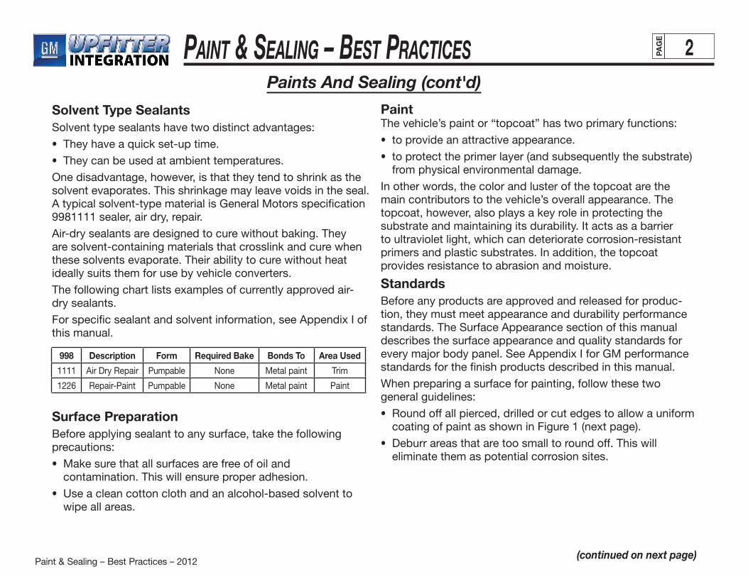
998 Description Form Required Bake Bonds To Area Used
1111 Air Dry Repair Pumpable None Metal paint Trim
1226 Repair-Paint Pumpable None Metal paint Paint
Surface PreparationBefore applying sealant to any surface, take the following precautions:
• Make sure that all surfaces are free of oil and contamination. This will ensure proper adhesion.
• Use a clean cotton cloth and an alcohol-based solvent to wipe all areas.
PaintThe vehicle’s paint or “topcoat” has two primary functions:
• to provide an attractive appearance.
• to protect the primer layer (and subsequently the substrate) from physical environmental damage.
In other words, the color and luster of the topcoat are the main contributors to the vehicle’s overall appearance. The topcoat, however, also plays a key role in protecting the substrate and maintaining its durability. It acts as a barrier to ultraviolet light, which can deteriorate corrosion-resistant primers and plastic substrates. In addition, the topcoat provides resistance to abrasion and moisture.
StandardsBefore any products are approved and released for produc-tion, they must meet appearance and durability performance standards. The Surface Appearance section of this manual describes the surface appearance and quality standards for every major body panel. See Appendix I for GM performance standards for the finish products described in this manual.
When preparing a surface for painting, follow these two general guidelines:
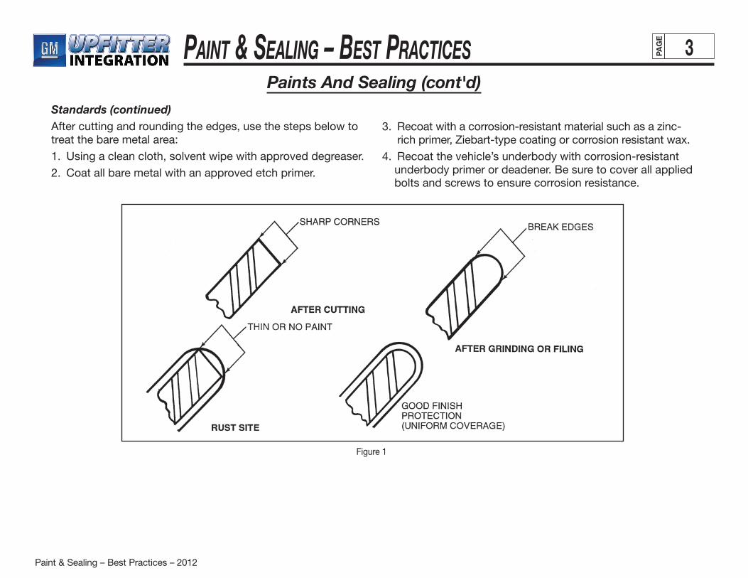
• Round off all pierced, drilled or cut edges to allow a uniform coating of paint as shown in Figure 1 (next page).
• Deburr areas that are too small to round off. This will eliminate them as potential corrosion sites.
Paint & Sealing – Best Practices – 2012
Paint & Sealing – BeSt PracticeS 3PAG
E
Paints And Sealing (cont'd)Standards (continued)After cutting and rounding the edges, use the steps below to treat the bare metal area:
1. Using a clean cloth, solvent wipe with approved degreaser.
2. Coat all bare metal with an approved etch primer.
3. Recoat with a corrosion-resistant material such as a zinc-rich primer, Ziebart-type coating or corrosion resistant wax.
4. Recoat the vehicle’s underbody with corrosion-resistant underbody primer or deadener. Be sure to cover all applied bolts and screws to ensure corrosion resistance.
Figure 1
Paint & Sealing – Best Practices – 2012
Paint & Sealing – BeSt PracticeS 4PAG
E
Surface Appearance
(continued on next page)
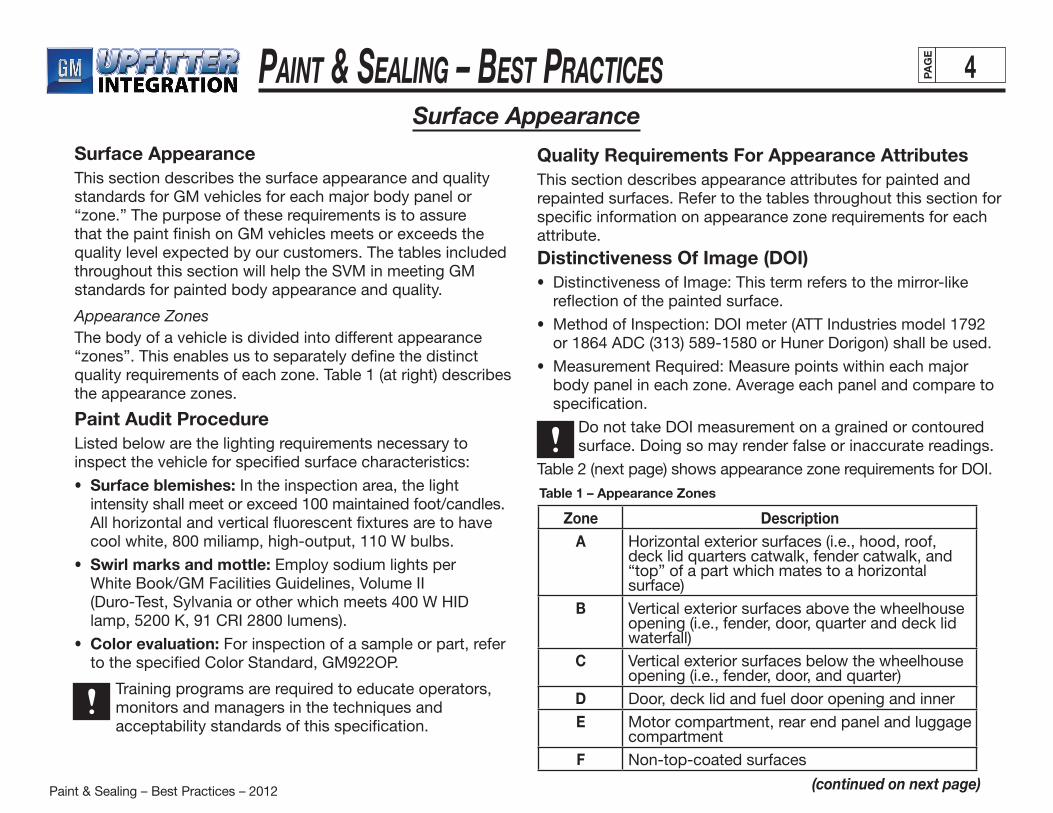
Surface AppearanceThis section describes the surface appearance and quality standards for GM vehicles for each major body panel or “zone.” The purpose of these requirements is to assure that the paint finish on GM vehicles meets or exceeds the quality level expected by our customers. The tables included throughout this section will help the SVM in meeting GM standards for painted body appearance and quality.
Appearance ZonesThe body of a vehicle is divided into different appearance “zones”. This enables us to separately define the distinct quality requirements of each zone. Table 1 (at right) describes the appearance zones.
Paint Audit ProcedureListed below are the lighting requirements necessary to inspect the vehicle for specified surface characteristics:
• Surface blemishes: In the inspection area, the light intensity shall meet or exceed 100 maintained foot/candles. All horizontal and vertical fluorescent fixtures are to have cool white, 800 miliamp, high-output, 110 W bulbs.
• Swirl marks and mottle: Employ sodium lights per White Book/GM Facilities Guidelines, Volume II (Duro-Test, Sylvania or other which meets 400 W HID lamp, 5200 K, 91 CRI 2800 lumens).
• Color evaluation: For inspection of a sample or part, refer to the specified Color Standard, GM922OP.
Training programs are required to educate operators, monitors and managers in the techniques and acceptability standards of this specification.
Zone DescriptionA Horizontal exterior surfaces (i.e., hood, roof,
deck lid quarters catwalk, fender catwalk, and “top” of a part which mates to a horizontal surface)
B Vertical exterior surfaces above the wheelhouse opening (i.e., fender, door, quarter and deck lid waterfall)
C Vertical exterior surfaces below the wheelhouse opening (i.e., fender, door, and quarter)
D Door, deck lid and fuel door opening and innerE Motor compartment, rear end panel and luggage
compartmentF Non-top-coated surfaces
Table 1 – Appearance Zones
Quality Requirements For Appearance AttributesThis section describes appearance attributes for painted and repainted surfaces. Refer to the tables throughout this section for specific information on appearance zone requirements for each attribute.
Distinctiveness Of Image (DOI)• Distinctiveness of Image: This term refers to the mirror-like
reflection of the painted surface.
• Method of Inspection: DOI meter (ATT Industries model 1792 or 1864 ADC (313) 589-1580 or Huner Dorigon) shall be used.
• Measurement Required: Measure points within each major body panel in each zone. Average each panel and compare to specification.
Do not take DOI measurement on a grained or contoured surface. Doing so may render false or inaccurate readings.
Table 2 (next page) shows appearance zone requirements for DOI.
Paint & Sealing – Best Practices – 2012
Paint & Sealing – BeSt PracticeS 5PAG
E
(continued on next page)
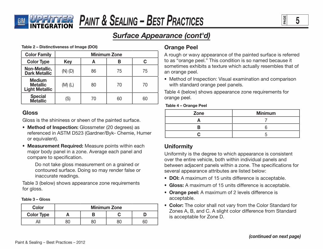
Color Family Minimum ZoneColor Type Key A B C
Non-Metallic, Dark Metallic (N) (D) 86 75 75
Medium Metallic
Light Metallic(M) (L) 80 70 70
Special Metallic (S) 70 60 60
Table 2 – Distinctiveness of Image (DOI)
Surface Appearance (cont'd)
GlossGloss is the shininess or sheen of the painted surface.
• Method of Inspection: Glossmeter (20 degrees) as referenced in ASTM D523 (Gardner/Byk- Chemie, Humer or equivalent).
• Measurement Required: Measure points within each major body panel in a zone. Average each panel and compare to specification.
Do not take gloss measurement on a grained or contoured surface. Doing so may render false or inaccurate readings.
Table 3 (below) shows appearance zone requirementsfor gloss.
Color Minimum ZoneColor Type A B C D
All 80 80 80 60
Table 3 – Gloss
Orange PeelA rough or wavy appearance of the painted surface is referred to as “orange peel.” This condition is so named because it sometimes exhibits a texture which actually resembles that of an orange peel.
• Method of Inspection: Visual examination and comparison with standard orange peel panels.
Table 4 (below) shows appearance zone requirements for orange peel.
Zone MinimumA 7B 6C 5
Table 4 – Orange Peel
UniformityUniformity is the degree to which appearance is consistent over the entire vehicle, both within individual panels and between adjacent panels within a zone. The specifications for several appearance attributes are listed below:
• DOI: A maximum of 15 units difference is acceptable.
• Gloss: A maximum of 15 units difference is acceptable.
• Orange peel: A maximum of 2 levels difference is acceptable.
• Color: The color shall not vary from the Color Standard for Zones A, B, and C. A slight color difference from Standard is acceptable for Zone D.
Paint & Sealing – Best Practices – 2012
Paint & Sealing – BeSt PracticeS 6PAG
E
Surface Appearance (cont'd)
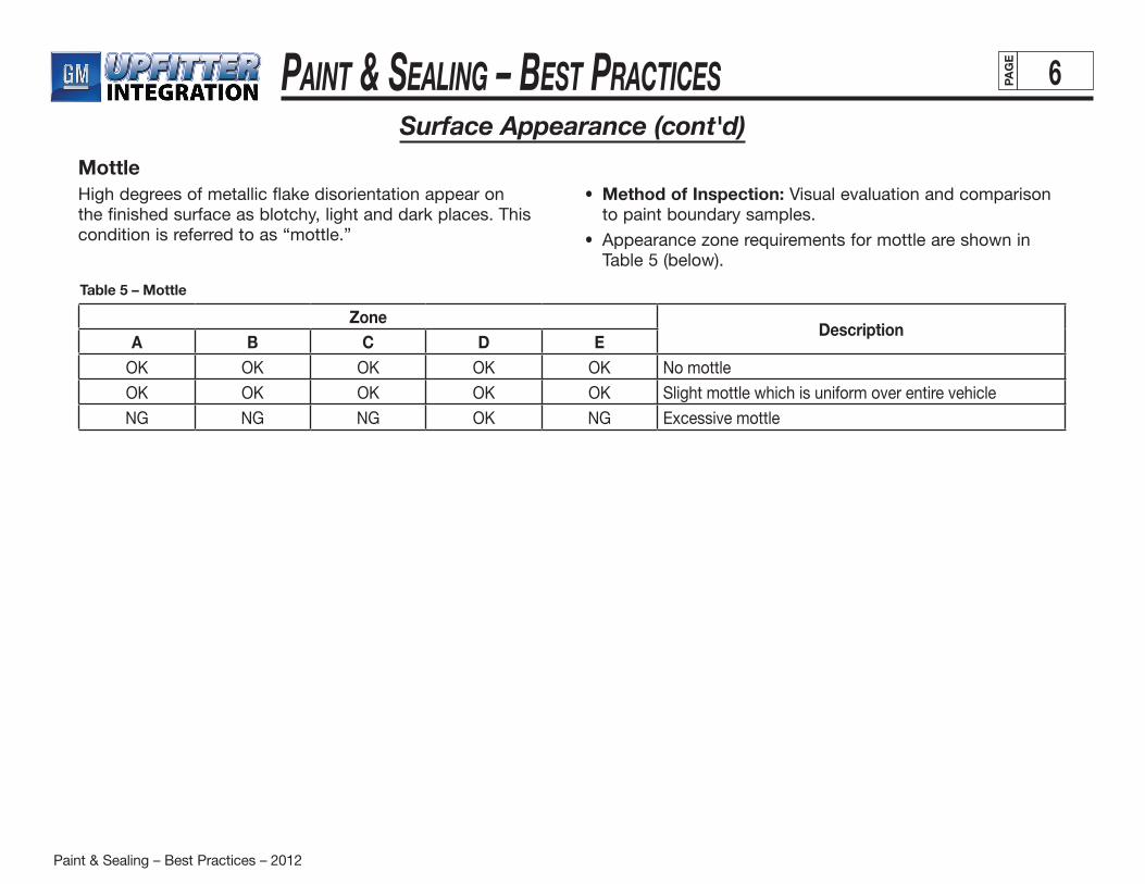
MottleHigh degrees of metallic flake disorientation appear on the finished surface as blotchy, light and dark places. This condition is referred to as “mottle.”
• Method of Inspection: Visual evaluation and comparison to paint boundary samples.
• Appearance zone requirements for mottle are shown in Table 5 (below).
ZoneDescription
A B C D EOK OK OK OK OK No mottle
OK OK OK OK OK Slight mottle which is uniform over entire vehicle
NG NG NG OK NG Excessive mottle
Table 5 – Mottle
Paint & Sealing – Best Practices – 2012
Paint & Sealing – BeSt PracticeS 7PAG
E
(continued on next page)
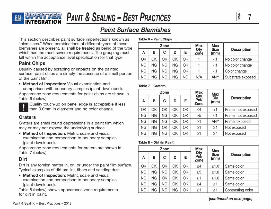
Paint Surface BlemishesThis section describes paint surface imperfections known as “blemishes.” When combinations of different types of these blemishes are present, all shall be treated as being of the type which has the most severe requirements. The grouping must fall within the acceptance level specification for that type.
Paint ChipsUsually caused by scraping or impacts on the painted surface, paint chips are simply the absence of a small portion of the paint film.• Method of Inspection: Visual examination and
comparison with boundary samples (plant developed).Appearance zone requirements for paint chips are shown in Table 6 (below). Quality touch-up on panel edge is acceptable if less
than 3.0mm in diameter and no color change.
CratersCraters are small round depressions in a paint film which may or may not expose the underlying surface.• Method of Inspection: Metric scale and visual
examination and comparison to boundary samples (plant developed).
Appearance zone requirements for craters are shown in Table 7 (below).
DirtDirt is any foreign matter in, on, or under the paint film surface. Typical examples of dirt are lint, fibers and sanding dust.• Method of Inspection: Metric scale and visual
examination and comparison to boundary samples (plant developed).
Table 8 (below) shows appearance zone requirementsfor dirt in paint.
Zone Max Qty
Zone
Max Size (mm)
DescriptionA B C D E
OK OK OK OK OK 1 <1 No color change
NG NG NG NG OK 1 <1 No color change
NG NG NG NG OK 1 <1 Color change
NG NG NG NG NG N/A ANY Substrate exposed
Table 6 – Paint Chips
Zone Max Qty Pnl/ Zone
Max Dia
(mm)Description
A B C D E
OK OK OK OK OK <_4 <1 Primer not exposed
NG NG NG OK OK >_5 <_1 Primer not exposed
NG NG NG OK OK >_1 ANY Primer exposed
NG NG OK OK OK >_1 >_1 Not exposed
NG NG NG OK OK >_1 >_4 Not exposed
Table 7 – Craters
Zone Max Qty Pnl/ Zone
Max Size (mm)
DescriptionA B C D E
OK OK OK OK OK <_4 <_1.0 Same color
NG NG NG OK OK >_5 <_1.0 Same color
NG NG OK OK OK >_1 >_1.0 Same color
NG NG NG OK OK >_4 >_1 Same color
NG NG NG NG OK >_1 >_1 Contrasting color
Table 8 – Dirt (In Paint)
Paint & Sealing – Best Practices – 2012
Paint & Sealing – BeSt PracticeS 8PAG
E
Paint Surface Blemishes (cont'd)
(continued on next page)
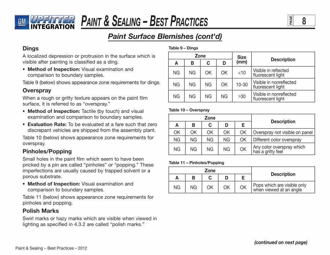
DingsA localized depression or protrusion in the surface which is visible after painting is classified as a ding.
• Method of Inspection: Visual examination and comparison to boundary samples.
Table 9 (below) shows appearance zone requirements for dings.
OversprayWhen a rough or gritty texture appears on the paint film surface, it is referred to as “overspray.”
• Method of Inspection: Tactile (by touch) and visual examination and comparison to boundary samples.
• Evaluation Rate: To be evaluated at a fare such that zero discrepant vehicles are shipped from the assembly plant.
Table 10 (below) shows appearance zone requirements for overspray.
Pinholes/PoppingSmall holes in the paint film which seem to have been pricked by a pin are called “pinholes” or “popping.” These imperfections are usually caused by trapped solvent or a porous substrate.
• Method of Inspection: Visual examination and comparison to boundary samples.
Table 11 (below) shows appearance zone requirements for pinholes and popping.
Polish MarksSwirl marks or hazy marks which are visible when viewed in lighting as specified in 4.3.2 are called “polish marks.”
Zone Size (mm) Description
A B C D
NG NG OK OK <10 Visible in reflected fluorescent light
NG NG NG OK 10-30 Visible in nonreflected fluorescent light
NG NG NG NG > 30 Visible in nonreflected fluorescent light
Table 9 – Dings
ZoneDescription
A B C D EOK OK OK OK OK Overspray not visible on panel
NG NG NG NG OK Different color overspray
NG NG NG NG OK Any color overspray which has a gritty feel
Table 10 – Overspray
ZoneDescription
A B C D E
NG NG OK OK OK Pops which are visible only when viewed at an angle
Table 11 – Pinholes/Popping
Paint & Sealing – Best Practices – 2012
Paint & Sealing – BeSt PracticeS 9PAG
E
Paint Surface Blemishes (cont'd)
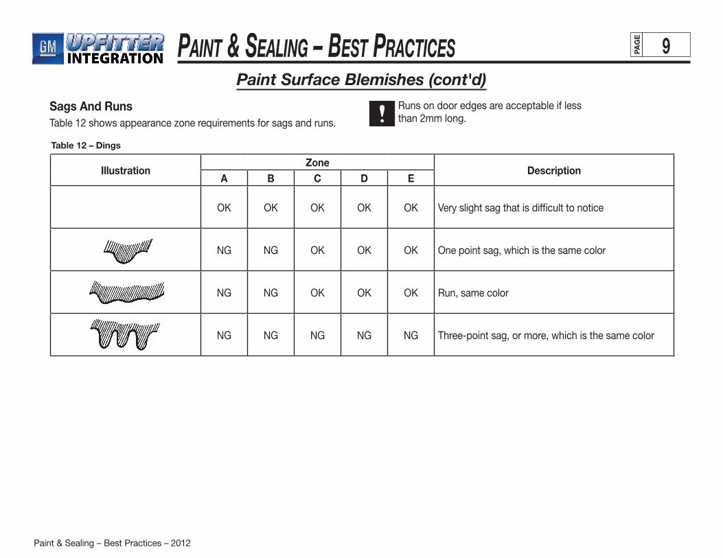
Sags And RunsTable 12 shows appearance zone requirements for sags and runs.
Runs on door edges are acceptable if lessthan 2mm long.
IllustrationZone
DescriptionA B C D E
OK OK OK OK OK Very slight sag that is difficult to notice
NG NG OK OK OK One point sag, which is the same color
NG NG OK OK OK Run, same color
NG NG NG NG NG Three-point sag, or more, which is the same color
Table 12 – Dings
Paint & Sealing – Best Practices – 2012
Paint & Sealing – BeSt PracticeS 10PAG
E
Painted Body Appearance
(continued on next page)
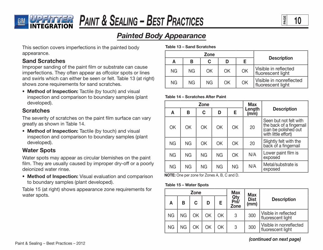
This section covers imperfections in the painted body appearance.
Sand ScratchesImproper sanding of the paint film or substrate can cause imperfections. They often appear as offcolor spots or lines and swirls which can either be seen or felt. Table 13 (at right) shows zone requirements for sand scratches.
• Method of Inspection: Tactile (by touch) and visual inspection and comparison to boundary samples (plant developed).
ScratchesThe severity of scratches on the paint film surface can vary greatly as shown in Table 14.
• Method of Inspection: Tactile (by touch) and visual inspection and comparison to boundary samples (plant developed).
Water SpotsWater spots may appear as circular blemishes on the paint film. They are usually caused by improper dry-off or a poorly deionized water rinse.
• Method of Inspection: Visual evaluation and comparison to boundary samples (plant developed).
Table 15 (at right) shows appearance zone requirements for water spots.
ZoneDescription
A B C D E
NG NG OK OK OK Visible in reflected fluorescent light
NG NG NG OK OK Visible in nonreflected fluorescent light
Table 13 – Sand Scratches
Zone Max Qty Pnl/Zone
Max Dist (mm)
DescriptionA B C D E
NG NG OK OK OK 3 300 Visible in reflected fluorescent light
NG NG OK OK OK 3 300 Visible in nonreflected fluorescent light
Table 15 – Water Spots
Zone Max Length (mm)
DescriptionA B C D E
OK OK OK OK OK 20Seen but not felt with the back of a fingernail (can be polished out with little effort)
NG NG OK OK OK 20 Slightly felt with the back of a fingernail
NG NG NG NG OK N/A Lower paint film is exposed
NG NG NG NG NG N/A Metal/substrate is exposed
Table 14 – Scratches After Paint
NOTE: One per zone for Zones A, B, C and D.
Paint & Sealing – Best Practices – 2012
Paint & Sealing – BeSt PracticeS 11PAG
E
Painted Body Appearance (cont'd)
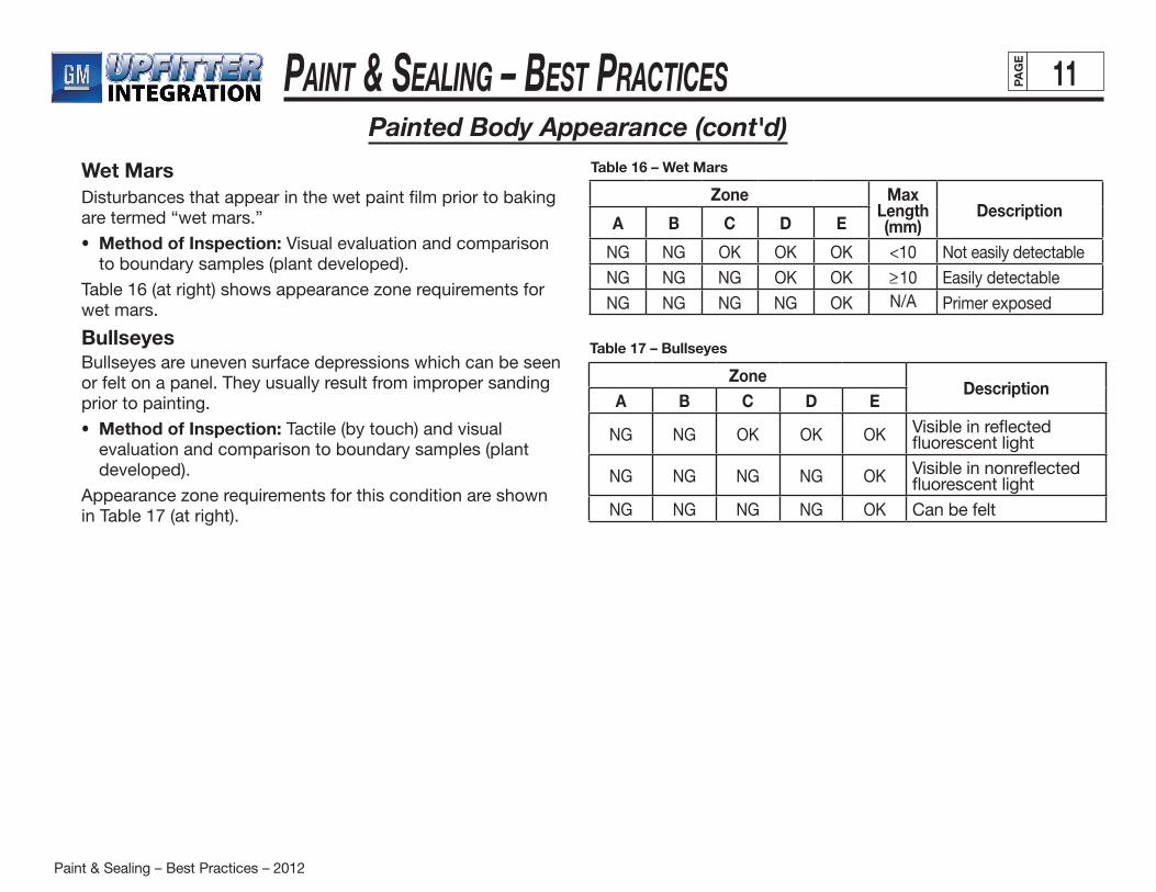
Wet MarsDisturbances that appear in the wet paint film prior to baking are termed “wet mars.”
• Method of Inspection: Visual evaluation and comparison to boundary samples (plant developed).
Table 16 (at right) shows appearance zone requirements for wet mars.
BullseyesBullseyes are uneven surface depressions which can be seen or felt on a panel. They usually result from improper sanding prior to painting.
• Method of Inspection: Tactile (by touch) and visual evaluation and comparison to boundary samples (plant developed).
Appearance zone requirements for this condition are shown in Table 17 (at right).
ZoneDescription
A B C D E
NG NG OK OK OK Visible in reflected fluorescent light
NG NG NG NG OK Visible in nonreflected fluorescent light
NG NG NG NG OK Can be felt
Table 17 – Bullseyes
Zone Max Length (mm)
DescriptionA B C D E
NG NG OK OK OK <10 Not easily detectable
NG NG NG OK OK >_10 Easily detectable
NG NG NG NG OK N/A Primer exposed
Table 16 – Wet Mars
Paint & Sealing – Best Practices – 2012
Paint & Sealing – BeSt PracticeS 12PAG
E
Appearance Zones
(continued on next page)
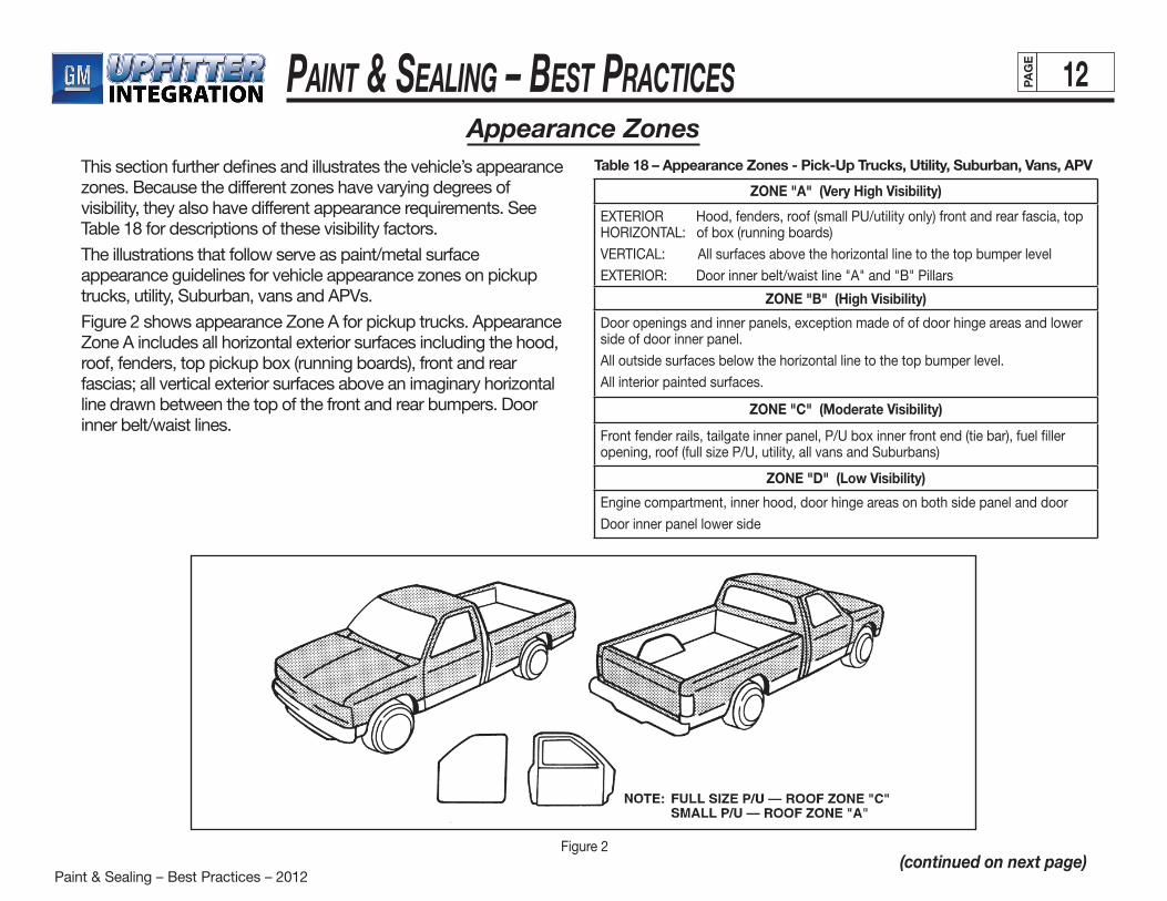
This section further defines and illustrates the vehicle’s appearance zones. Because the different zones have varying degrees of visibility, they also have different appearance requirements. See Table 18 for descriptions of these visibility factors.
The illustrations that follow serve as paint/metal surface appearance guidelines for vehicle appearance zones on pickup trucks, utility, Suburban, vans and APVs.
Figure 2 shows appearance Zone A for pickup trucks. Appearance Zone A includes all horizontal exterior surfaces including the hood, roof, fenders, top pickup box (running boards), front and rear fascias; all vertical exterior surfaces above an imaginary horizontal line drawn between the top of the front and rear bumpers. Door inner belt/waist lines.
ZONE "A" (Very High Visibility)
EXTERIOR Hood, fenders, roof (small PU/utility only) front and rear fascia, top HORIZONTAL: of box (running boards)
VERTICAL: All surfaces above the horizontal line to the top bumper level
EXTERIOR: Door inner belt/waist line "A" and "B" Pillars
ZONE "B" (High Visibility)
Door openings and inner panels, exception made of of door hinge areas and lower side of door inner panel.
All outside surfaces below the horizontal line to the top bumper level.
All interior painted surfaces.
ZONE "C" (Moderate Visibility)
Front fender rails, tailgate inner panel, P/U box inner front end (tie bar), fuel filler opening, roof (full size P/U, utility, all vans and Suburbans)
ZONE "D" (Low Visibility)
Engine compartment, inner hood, door hinge areas on both side panel and door
Door inner panel lower side
Figure 2
Table 18 – Appearance Zones - Pick-Up Trucks, Utility, Suburban, Vans, APV
Paint & Sealing – Best Practices – 2012
Paint & Sealing – BeSt PracticeS 13PAG
E
Appearance Zones (cont'd)
(continued on next page)
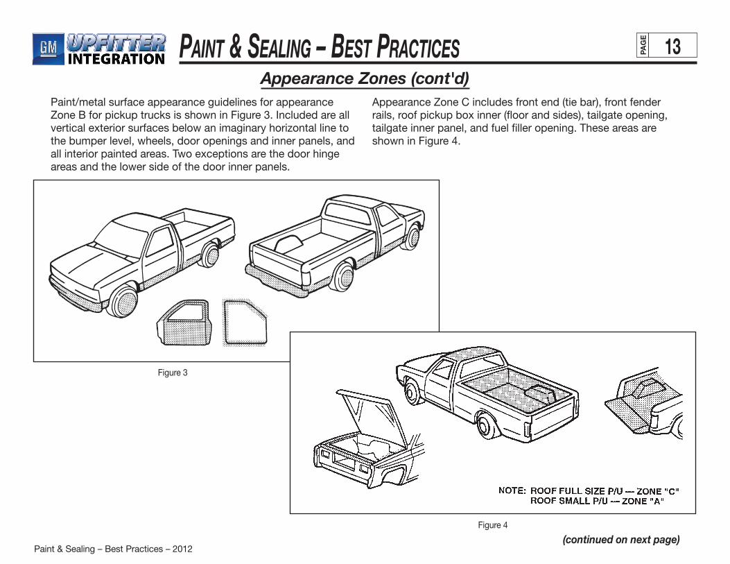
Paint/metal surface appearance guidelines for appearance Zone B for pickup trucks is shown in Figure 3. Included are all vertical exterior surfaces below an imaginary horizontal line to the bumper level, wheels, door openings and inner panels, and all interior painted areas. Two exceptions are the door hinge areas and the lower side of the door inner panels.
Appearance Zone C includes front end (tie bar), front fender rails, roof pickup box inner (floor and sides), tailgate opening, tailgate inner panel, and fuel filler opening. These areas are shown in Figure 4.
Figure 3
Figure 4
Paint & Sealing – Best Practices – 2012
Paint & Sealing – BeSt PracticeS 14PAG
E
(continued on next page)
Figure 5
Figure 6
Appearance Zones (cont'd)
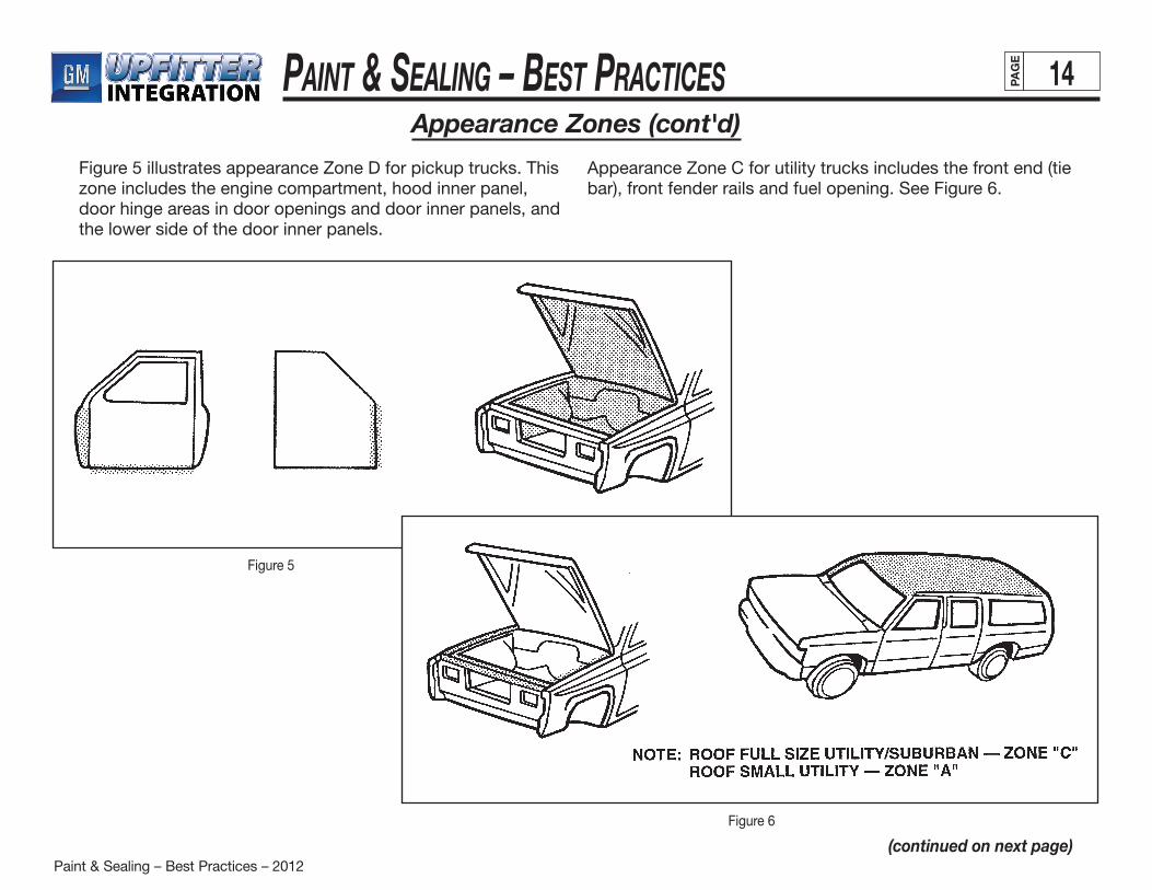
Figure 5 illustrates appearance Zone D for pickup trucks. This zone includes the engine compartment, hood inner panel, door hinge areas in door openings and door inner panels, and the lower side of the door inner panels.
Appearance Zone C for utility trucks includes the front end (tie bar), front fender rails and fuel opening. See Figure 6.
Paint & Sealing – Best Practices – 2012
Paint & Sealing – BeSt PracticeS 15PAG
E
Figure 7
(continued on next page)
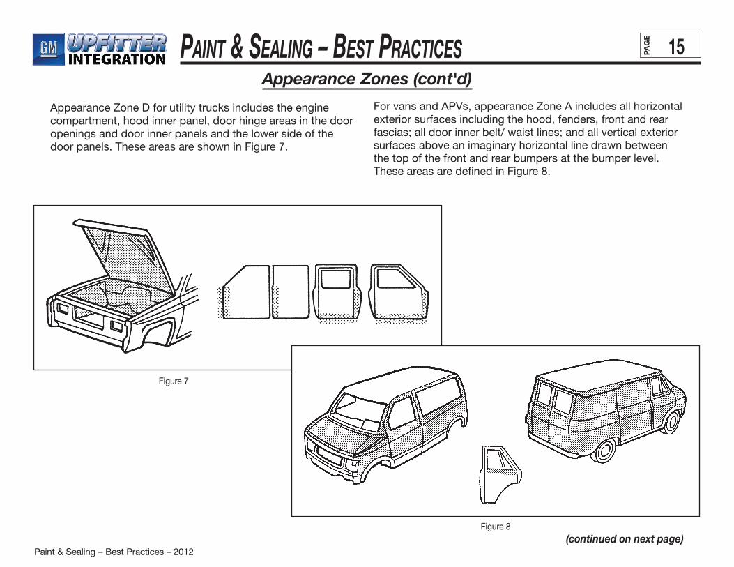
Appearance Zone D for utility trucks includes the engine compartment, hood inner panel, door hinge areas in the door openings and door inner panels and the lower side of the door panels. These areas are shown in Figure 7.
Figure 8
For vans and APVs, appearance Zone A includes all horizontal exterior surfaces including the hood, fenders, front and rear fascias; all door inner belt/ waist lines; and all vertical exterior surfaces above an imaginary horizontal line drawn between the top of the front and rear bumpers at the bumper level. These areas are defined in Figure 8.
Appearance Zones (cont'd)
Paint & Sealing – Best Practices – 2012
Paint & Sealing – BeSt PracticeS 16PAG
E
(continued on next page)
Appearance Zones (cont'd)
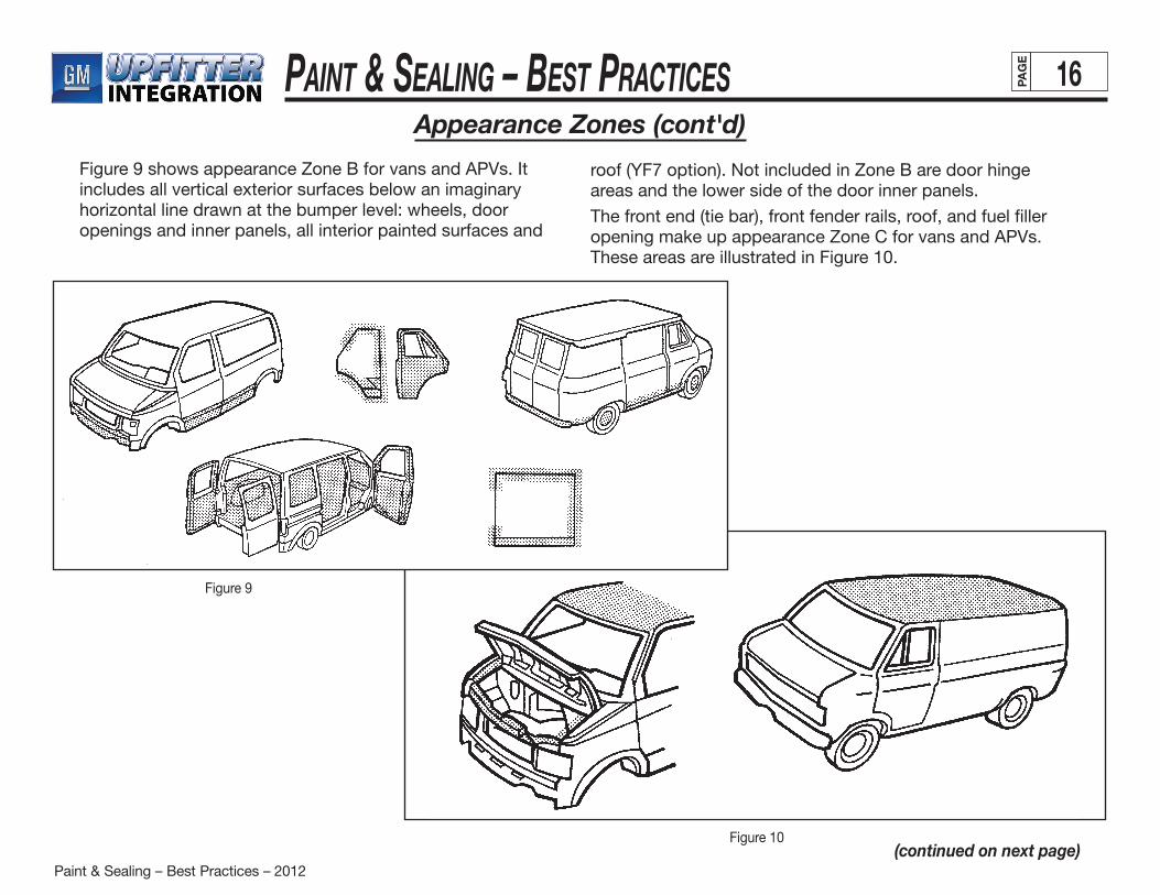
Figure 9 shows appearance Zone B for vans and APVs. It includes all vertical exterior surfaces below an imaginary horizontal line drawn at the bumper level: wheels, door openings and inner panels, all interior painted surfaces and
roof (YF7 option). Not included in Zone B are door hingeareas and the lower side of the door inner panels.
The front end (tie bar), front fender rails, roof, and fuel filler opening make up appearance Zone C for vans and APVs. These areas are illustrated in Figure 10.
Figure 10
Figure 9
Paint & Sealing – Best Practices – 2012
Paint & Sealing – BeSt PracticeS 17PAG
E
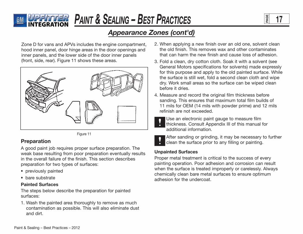
Zone D for vans and APVs includes the engine compartment, hood inner panel, door hinge areas in the door openings and inner panels, and the lower side of the door inner panels (front, side, rear). Figure 11 shows these areas.
Appearance Zones (cont'd)
Figure 11
PreparationA good paint job requires proper surface preparation. The weak base resulting from poor preparation eventually results in the overall failure of the finish. This section describes preparation for two types of surfaces:
• previously painted
• bare substrate
Painted SurfacesThe steps below describe the preparation for painted surfaces:
1. Wash the painted area thoroughly to remove as much contamination as possible. This will also eliminate dust and dirt.
2. When applying a new finish over an old one, solvent clean the old finish. This removes wax and other contaminates that can harm the new finish and cause loss of adhesion.
3. Fold a clean, dry cotton cloth. Soak it with a solvent (see General Motors specifications for solvents) made expressly for this purpose and apply to the old painted surface. While the surface is still wet, fold a second clean cloth and wipe dry. Work small areas so the surface can be wiped clean before it dries.
4. Measure and record the original film thickness before sanding. This ensures that maximum total film builds of 11 mils for OEM (14 mils with powder prime) and 12 mils refinish are not exceeded.
Use an electronic paint gauge to measure film thickness. Consult Appendix III of this manual for additional information.
After sanding or grinding, it may be necessary to further clean the surface prior to any filling or painting.
Unpainted SurfacesProper metal treatment is critical to the success of every painting operation. Poor adhesion and corrosion can result when the surface is treated improperly or carelessly. Always chemically clean bare metal surfaces to ensure optimum adhesion for the undercoat.
Paint & Sealing – Best Practices – 2012
Paint & Sealing – BeSt PracticeS 18PAG
E
(continued on next page)
Paint Systems And Procedures
GM-Approved Refinish MaterialsGeneral Motors continuously pursues quality improvement. Therefore GM has established automotive refinishing standards for itself as well as its Marketing Division Dealers and Retailers. GM is the first domestic car company to set a specification for aftermarket paint finishes.
GM has established standards for paint refinishing. Each Division requires the Dealer to use only materials and methods that meet GM Standard GM4901M when repairing, replacing, or refinishing vehicles. Where it is determined that the Dealer is using paint systems or materials which do not meet GM4901M standards, appropriate counsel and/or corrective action may be taken.
The Bottom LineThe Dealer or Retailer must ensure that all finish repairs, including sublets, meet GM Specification GM4901M. Use of materials (and associated methods) that do not meet this GM standard may result in a review of claim(s) leading to chargeback(s).
As warranty periods increase, customer expectations continue to rise. Many Dealers/Retailers understand customer expectations. As a result, they have chosen a single, complete system approach and only use the systems that meet the highest standards of quality and durability.
All the paint manufacturers that meet the GM4901M Specification have spent thousands of manhours in research and development to ensure the approved system gives the appearance, performance, and durability comparable to the OEM finish. The products in the systems listed in this bookare the very best products to use. They are guaranteed to produce the consistent, quality results that GM customers expect. This makes it easier for you, as the Dealer/Retailer,
to confidently choose a system that will maximize your customers’ satisfaction.
Each year, all new paint systems will be tested and evaluated. New or improved products will also be tested. The paint systems that pass this annual testing process will be published in this booklet, updated annually.
For further information on these systems, call the STG Center, at 1-810-575-1906.
If booklets are needed, call 1-800-269-5100.See Appendix II of this manual for additional information for GM4901M standards and approved sources.
UndercoatsLike surface preparation, proper undercoating is necessary to achieve an attractive, durable topcoat. It is important to use the right undercoat for the job and to apply it promptly following surface preparation.
There are four types of undercoats:
• Prepcoats
• Primer-surfacers
• Primer-sealers
• Sealers
Paint & Sealing – Best Practices – 2012
Paint & Sealing – BeSt PracticeS 19PAG
E
(continued on next page)
Paint Systems And Procedures (cont'd)
Prepcoats (Etch Primers)Prepcoats prepare the bare metal substrate to accept and hold the color coat. They do this by providing adhesion to the surface and producing a corrosion-resistant foundation. Prepcoats do not fill well and are used in conjunction with a primer-surfacer.
Self-etching prepcoats provide excellent adhesion. Also used as prepcoats are zinc chromate primers, which protect steel and aluminum against rusting or corrosion. Prior to assembly, a coat of this primer can be sprayed where dissimilar metalscontact each other. This prevents the electrolytic action that causes rapid corrosion of the metal.
Primer-SurfacersApplied prior to basecoat clear coat application, primer-surfacers build up the base required for sanding. GM recommends two applications of primer-surfacer, with the second application color keyed to topcoat.
Good primer-surfacer characteristics are:
• The ability to create a strong bond or adhesion between the substrate and the applied topcoat.
• Corrosion resistance to prevent disintegration of the metallic substrate.
• The ability to “build” or cover all surface imperfections (i.e., grind marks, sand scratches, etc.).
• Ability to sand smoothly and level quickly and easily.
• “Hold out” or sealing quality to prevent the topcoat from “striking” into the film causing a dull look.
• Quick drying speed, allowing sanding within a reasonable time.
Always measure primer quality per GM specifications (see Appendix I).
Primer-SealersPrimer-sealers provide the same protection as prepcoats: adhesion and corrosion resistance. They also have the ability to seal a sanded old finish to provide uniform color hold-out.
Primer-sealers can be used to prime a bare surface and as a sealer under any enamel topcoat.
Sealers (Adhesion Promoters)Sealers perform three basic functions:
• Improve adhesion between the old finish and the new
• Provide uniform color background and holdout for the topcoat
• Provide a solvent barrier to help prevent sandscratch swelling and show-through
Unlike primers, sealers are sprayed over prepcoats, primer surfaces, or sanded old finishes.
Clearcoat areas must be sealed prior to repainting.
• Sealers are not used as primers. They are sprayed over prepcoats or primer surfaces, or sanded old finishes.
• Before applying a sealer, all surfaces must be thoroughly scuff-sanded (no glossy areas). This prevents delamination.
Paint & Sealing – Best Practices – 2012
Paint & Sealing – BeSt PracticeS 20PAG
E
(continued on next page)
Putties And FillersPutties and body fillers (while not precisely undercoats) can be termed “solid” undercoats.
• A putty is a paste and has a much heavier body than a primer-surfacer. It is used to fill any small imperfections or flaws remaining in the substrate after primer-surfacer has been applied. Putty must be sanded.
• Body fillers are an extremely durable polyester plastic material that sands smooth after drying. It is used to fill large flaws before either primer or putty is applied.
TopcoatFrom the customer’s standpoint, the topcoat is the most important step in the painting operation. This is because the customer sees only the topcoat and judges the quality of the entire paint job on its appearance.
BasecoatThe first step in color matching is to select the proper topcoat color. Paint quality and durability must meet the requirements of GM specification 4901M (refinish materials).
ClearcoatClearcoat quality must meet the requirements of GM specification 4901M. A minimum thickness of 1.5 mils is necessary to protect the finish from ultraviolet penetration.
Accurate measurements of the clearcoat application ensures that the 1.5-mil minimum film-build is maintained. An OEM finish finessed to match the surface of the newly painted area must be accurately measured before and after finesse to ensure that 1.5 mils minimum of clearcoat remain on theunit (0.5 mil maximum clearcoat removal). See Appendix III of this manual for film thickness measuring device.
Paint Systems And Procedures (cont'd)
Finesse/Clear And PolishAccurate measurements of the clearcoat application ensures that the 1.5-mil minimum film-build is maintained. An OEM finish finessed to match the surface of the newly painted area must be accurately measured before and after finesse to ensure that 1.5 mils minimum of clearcoat remain on theunit (0.5 mil maximum clearcoat removal). See Appendix III of this manual for film thickness measuring device.
Sanding (Primer)Sanding removes defects from a surface and prepares it to receive a topcoat. Two methods are moist sanding and wet sanding. Great care must be taken with either method to avoid sand-through, which will adversely affect the appearance and durability of the finished product.Before any detail or hand-sand operation, it is important to classify exterior body panels as Zone A, B or C. Sharp edges or surface profiles not accessible by mechanical sanding should have an 8- to 12-mil gap between those areas and the areas sanded, as required. This gap range should alwaysbe detailed by hand.Sanding through the primer surface or electro-deposited primer is not acceptable. These important layers guard against accelerated corrosion and paint failure.
Moist SandingMoist sanding is one method of defect removal which is preferable to the more labor-intensive operation of complete wet sanding. It allows the operator to inspect the surface for visible defects — such as dirt and sags — prior to painting. Moist sanding should be performed in an enclosed booth to avoid contaminating the entire paint shop with sanding residue. Compatibility of the primer with water must be verified with the supplier.
Paint & Sealing – Best Practices – 2012
Paint & Sealing – BeSt PracticeS 21PAG
E
Moist Sanding (cont'd)The general sanding process follows:
1. Cool units to below 37.8ºC before sanding.
2. Use sandpaper with ANSI 400 grit or higher so that defects can be removed without producing sand scratches that are visible after topcoat application. If sand scratches are visible, reprocess with finer-grit sandpaper.
3. Thoroughly soak sandpaper prior to use. Spray area to be sanded with water to lubricate the work surface.
4. Remove the defect by sanding in a circular motion. This prevents uni-directional sand scratches.
5. Once the defect is removed, wipe the surface with a clean, lint-free cloth.
6. After removing all defects from the unit, wipe the entire surface with a 50/50 isopropyl alcohol/water mixture. This should remove any contamination that remains after moist sanding.
Tack-off, followed by air blow-off, must be completed before applying the next coat.
Wet SandingDepending on the surface contour, type of primer, and detail requirements of the unit, wet sanding may be preferable to mechanical methods.
The known hardness of the surfaces to be sanded and the surface profile of the unit determine theselection of equipment and materials (screen-cloth grit and size). Selection criteria should include (but not limited by) evaluation of sand scratches which result from the process and are not visible after topcoat application.
Maintaining a sufficient amount of water is critical to wet
sanding. This avoids uneven cutting of the unit surface. After the last wet sand operation, a high-pressure rinse is required to remove all excess surface contamination that could affect the topcoat or its durability. A final rinse of deionized (DI) water should follow to remove all salts or foreign materials that affect topcoat quality.
When wet sanding by mechanical methods, always use multiple, uniform cuts on horizontal and vertical surfaces. This ensures that wet sand screen swirl cuts and other defects are not visible after topcoat application. Rinse screens as often as necessary with water to free any wet sand residue or abrasive particles that may lodge within the screen itself.
IonizersSanding, finesse, detailing, tack-off and other assembly plant operations may deliver a static charge to the unit. The static charge in turn is a potential attraction for dirt or other surface contaminants. Ionizers are used to neutralize static charges. It is acceptable to use an ionizing air blow-off to blow dust, dirt and sanding particles from the unit. This process reduces static and imperfections in subsequent painting applications.
Paint Systems And Procedures (cont'd)
Paint & Sealing – Best Practices – 2012
Paint & Sealing – BeSt PracticeS 22PAG
E
Repair Systems
Paint defects which do not meet minimum GM Surface Appearance Standards, as determined by comparison to previous charts, should be repaired using the methods outlined in this section. Key Process Controls should be established to ensure that only a minimum of production requires paint repair.
• Defects in enamel which cannot be removed by buffing or polishing must be sanded thoroughly and repainted. Repaint only the defective panels. Avoid repainting entire units. The total refinish system, including topcoat filmbuild, should not exceed 12.0 mils (11 mils for OEM or 14 mils with powder prime).
• Use pressure-sensitive masking tape and masking paper to mask off panels that do not require repair.
A panel is an area bordered by molding edges, ornaments or a natural breakline which serves to hide the demarcation line between the repair paint and the original finish. Do not mask along a line in the middle of an open area. If necessary, multiple areas must be repainted. If the masking line becomes objectionable at any point, the condition can be alleviated by light sanding, buffing and polishing.
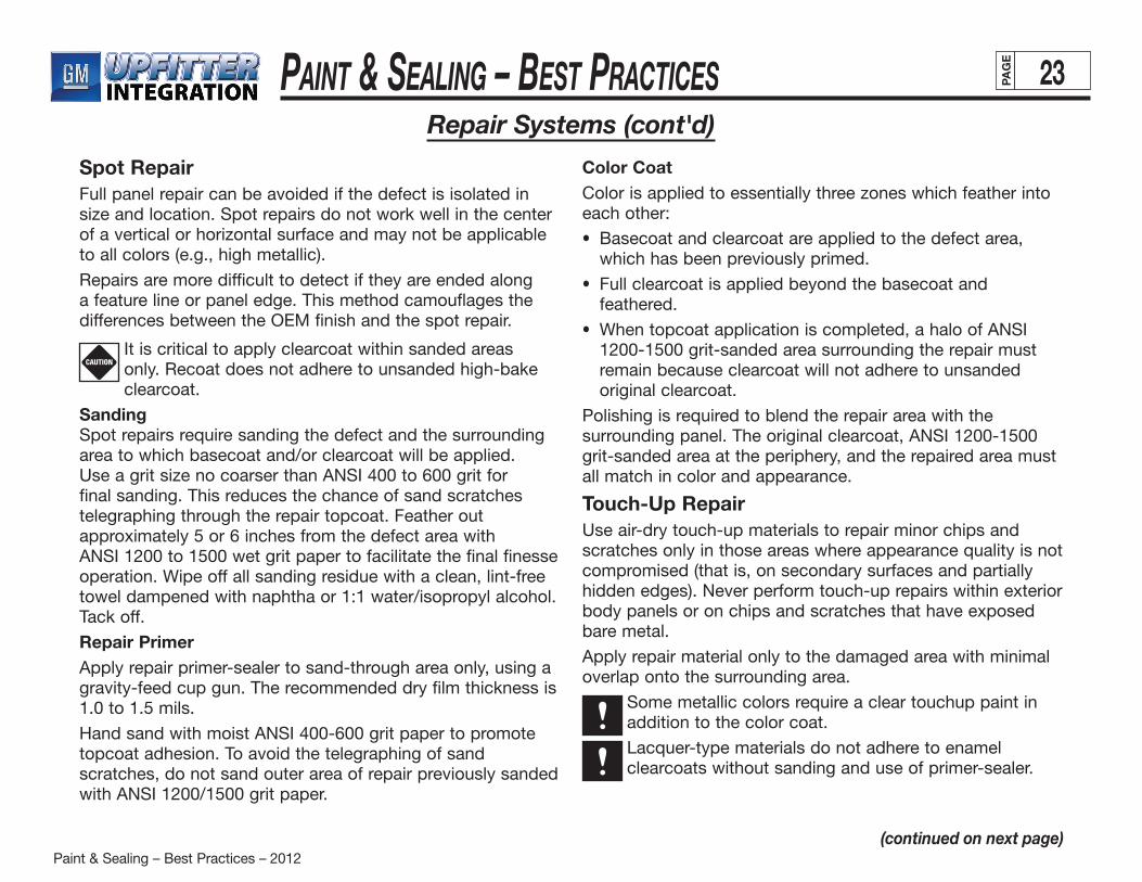
SandingRemove any film irregularity by block sanding with ANSI 400 or 600 grit paper. It is necessary to scuff-sand the complete surface to be painted to avoid surface conditions that could adversely affect intercoat adhesion. Always give specialattention to panel feature lines and depressions during scuff-sanding. After sanding, lightly wipe the entire panel surface with a tack cloth to remove sanding residues. See Figure 12 for proper hand sanding technique.
Repair Primer (Etch)A coat of cut-through repair primer must be applied to all areas in which sanding has exposed the bare metal. Follow all supplier application parameters to ensure that all required properties are achieved.
Apply two layers each of basecoat and clearcoat using spray parameters given for main color application. Repair of clearcoat over clearcoat tends to be more sensitive to intercoat adhesion failures. Full sanding of clearcoat is mandatory prior to recoating with clearcoat.
The repaired panel should match the original color and overall appearance as closely as possible.
Figure 12
(continued on next page)
Paint & Sealing – Best Practices – 2012
Paint & Sealing – BeSt PracticeS 23PAG
E
Spot RepairFull panel repair can be avoided if the defect is isolated in size and location. Spot repairs do not work well in the center of a vertical or horizontal surface and may not be applicable to all colors (e.g., high metallic).
Repairs are more difficult to detect if they are ended along a feature line or panel edge. This method camouflages the differences between the OEM finish and the spot repair.
It is critical to apply clearcoat within sanded areas only. Recoat does not adhere to unsanded high-bake clearcoat.
SandingSpot repairs require sanding the defect and the surrounding area to which basecoat and/or clearcoat will be applied. Use a grit size no coarser than ANSI 400 to 600 grit for final sanding. This reduces the chance of sand scratches telegraphing through the repair topcoat. Feather out approximately 5 or 6 inches from the defect area withANSI 1200 to 1500 wet grit paper to facilitate the final finesse operation. Wipe off all sanding residue with a clean, lint-free towel dampened with naphtha or 1:1 water/isopropyl alcohol. Tack off.
Repair PrimerApply repair primer-sealer to sand-through area only, using a gravity-feed cup gun. The recommended dry film thickness is 1.0 to 1.5 mils.
Hand sand with moist ANSI 400-600 grit paper to promote topcoat adhesion. To avoid the telegraphing of sand scratches, do not sand outer area of repair previously sanded with ANSI 1200/1500 grit paper.
Color CoatColor is applied to essentially three zones which feather into each other:
• Basecoat and clearcoat are applied to the defect area, which has been previously primed.
• Full clearcoat is applied beyond the basecoat and feathered.
• When topcoat application is completed, a halo of ANSI 1200-1500 grit-sanded area surrounding the repair must remain because clearcoat will not adhere to unsanded original clearcoat.
Polishing is required to blend the repair area with the surrounding panel. The original clearcoat, ANSI 1200-1500 grit-sanded area at the periphery, and the repaired area must all match in color and appearance.
Touch-Up RepairUse air-dry touch-up materials to repair minor chips and scratches only in those areas where appearance quality is not compromised (that is, on secondary surfaces and partially hidden edges). Never perform touch-up repairs within exteriorbody panels or on chips and scratches that have exposed bare metal.
Apply repair material only to the damaged area with minimal overlap onto the surrounding area.
Some metallic colors require a clear touchup paint in addition to the color coat.
Lacquer-type materials do not adhere to enamel clearcoats without sanding and use of primer-sealer.
CAUTION
Repair Systems (cont'd)
(continued on next page)
Paint & Sealing – Best Practices – 2012
Paint & Sealing – BeSt PracticeS 24PAG
E
(continued on next page)
Application of up to three coats (sealer, color coat and clearcoat) requires considerable finesse to obtain acceptable appearance. Some polishing may also be required.
Enamel-type touch-up materials are preferable.
Some general guidelines for touch-up repairs are:
• Clean the area surrounding chip or scratch with naphtha to remove any grease, oil or other contaminants. Wipe dry with a clean, dry, lint-free cloth.
• If application of repair material is limited to mutilated area, it is not necessary to sand or apply primer to obtain adhesion.
• If repair material is applied to adjacent area (1/8 inch maximum), apply a light coat of primer-sealer to the repair area. Do not apply sealer to areas which will not receive repair paint. Alternately, the adjacent area may be sanded with ANSI 600 grit sandpaper, followed by ANSI 1200 grit sandpaper. This allows polishing to remove sanding scratches if required.
• Apply sufficient color coat to achieve hiding and color match before applying clearcoat.
• Nominal film-builds are 1.5 to 2.0 mils.
• Ifnecessarytoblendrepairedspotwithsurroundingarea,allow to air dry for 24 hours (or equivalent using heat source) and finesse polish.
Repair Systems (cont'd)
Spot Finesse Sanding/PolishingBasecoat/ClearcoatThis process can be used to repair minor scratches, dirt, dull spots and related defects in the clearcoat without resorting to repainting. It may be performed before or after repairs. Do not use this method to repair major defects such as large sags, solvent pops, craters or basecoat defects.Prior to finesse and repair, inspect the body for all paint defects in a well-lighted area (100 foot-candle lighting minimum). Use this method only on paint which is sufficiently cured and has cooled to 100ºF or below. Otherwise, objectionable swirl marks and other appearance deficiencies may result. Be very careful during each step of the process to remove as little of the clearcoat as possible.
Removing DefectsThe approved method for removing defects, such as dirt protruding above the clearcoat surface, is by hand-planing with a file. You may attach a wood block to the file to facilitate the operation. Grasp the tool firmly. Gently shave the imperfection, using several strokes in one direction only.
Apply minimum pressure and concentrate in the area of the defect only to avoid removing the surrounding clearcoat.
Clean and sharpen the file periodically to achieve proper defect removal.
SandingAfter removing the defect, lightly hand-sand the area. Use a special finesse sanding block with ANSI 1200 or 1500 grit paper and lubricating fluid. Use a circular motion, applying minimum pressure to avoid deep scratches, until defect is uniform with surrounding area. After sanding, wipe the affected area with a clean, lint-free cloth.
CAUTION
Paint & Sealing – Best Practices – 2012
Paint & Sealing – BeSt PracticeS 25PAG
E
(continued on next page)
Repair Systems (cont'd)
Do not sand excessively around the defect area. Reducing the clearcoat’s thickness will affect durability.
A minimum of 1.5 mils clearcoat must remain (0.5 mil maximum removal). Otherwise, the affected area must be recoated.
Finesse Polish (Rotary)Follow the steps below to remove any fine scratches created by sanding:
1. Apply one 3/8 inch drop of specific finesse polishing compound per sanded spot.
2. Using a polish pad, evenly smear the compound over the sanded area before running the wheel.
3. While running the wheel, keep the pad flat, directly over the sanded spot. Operate the tool with a 1- to 2-inch circular motion to randomize the swirl pattern. Apply only enough pressure to maintain uniform contact with the surface. Polish panel edges and sharp contours lightly to avoid cut-through.
Inspect the polished area. Apply more polish, repeating as needed. When all sand scratches have been removed and the finish is uniform and glossy, the unit is ready for buffing. There is no need to remove polish residue.
Final Buffing (Orbital)Final orbital buffing removes any swirl marks left by rotary polishing.
Apply additional finesse polishing compound or specified finesse buffing compound to each polished spot. Using an orbital buffing wheel, evenly smear the compound over the polished spot before operating the wheel. Begin buffing in the center of the swirl pattern. Use a slight back-and-forthmotion and buff approximately 3 inches beyond the pattern. This will blend the refinished spot with the surrounding area.
Apply enough pressure to prevent free motion of the motor. Do not restrict the motor’s dual action. This action helps to minimize the objectionable continuous swirl pattern.
After buffing, mist the area with 50/50 water/ isopropyl alcohol blend. Wipe with a soft cloth to remove polish residue. Inspect the surface under sunlight or sodium vapor lights. If it is not uniform and free of swirls or haze, repeat the buffing operation.
CAUTION
Paint & Sealing – Best Practices – 2012
Paint & Sealing – BeSt PracticeS 26PAG
E
(continued on next page)
Manual Spray Guns And Applications
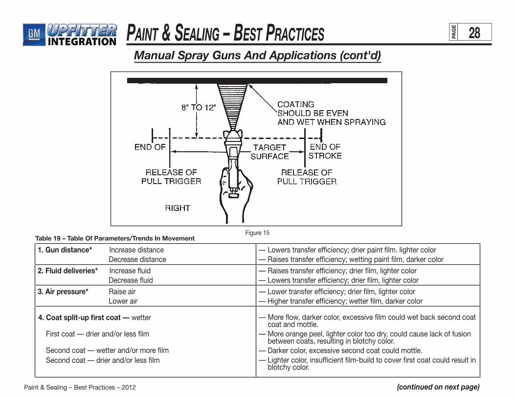
This section covers proper techniques for applying paint by hand. It is for informational purposes only. Major suppliers provide training in the proper spray application of their products. Specific questions should be addressed to them. See Appendix I of this manual for information on hand spray- gun operation and maintenance.Good hand spraying technique (Figures 13, 14, and 15) ensures a uniform surface of specified gloss, DOI, texture, film-build and color. Proper technique requires attention to many elements, including:
• fluiddeliverysettings
• applicationstrokeoverlapandlength
• triggeringpoints
• spraypatternadjustment
• surfacecontour
• paintmaterialcharacteristics
• film-buildrequirements
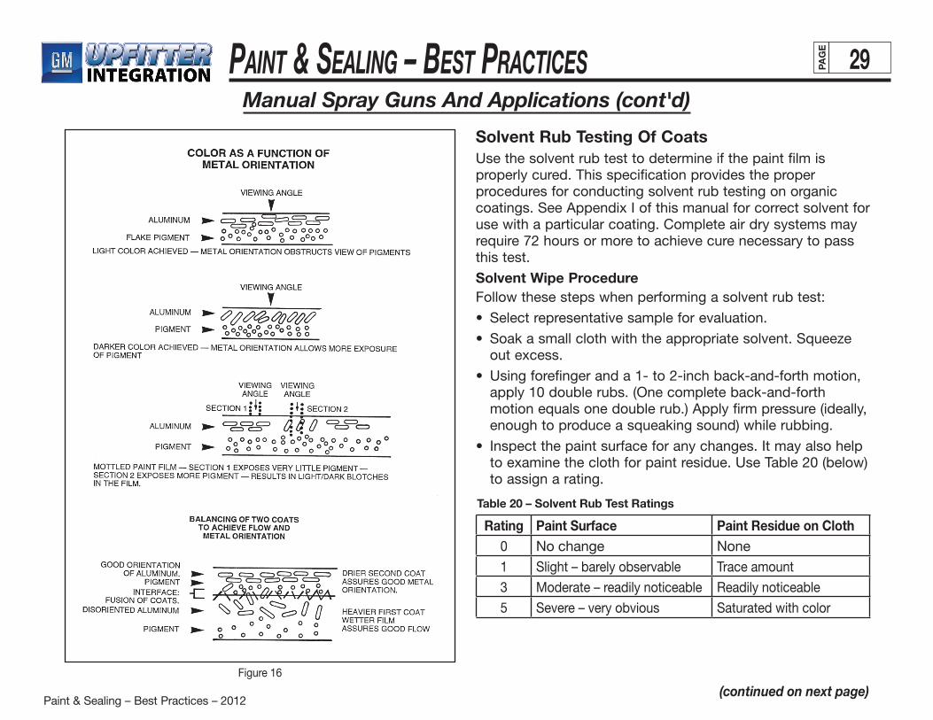
• handgun-to-workorientationanddistanceSeveral trial sprays may be necessary to establish an ideal, repeatable technique. The following table (Table 19) outlines topcoat process controls by describing the relationship between application parameters and appearance or perfor- mance attributes for typical processing situations. Para-meters are often interdependent. That is, changing one can influence another. Many of the “typical” cases indicate general trends only for specific parameters.Color is directly related to pigment strength, pigment loading, and degree of dispersion and metal flake orientation. Metal flake orientation is the area most influenced by application parameters. The orientation of metal determines how much pigment is exposed. See Figure 16 (on page 29).
• Lightercolorsareproducedwhenmorealuminumand less pigment is exposed.
• Darkercolorsresultfrommorealuminumdisorientation.• Highdegreesofmetaldisorientationcauseblotches,light
and dark patches commonly referred to as “mottle.”• Twofactorsinfluencemetalorientation: — the kinetic energy of the paint particle striking the
work place. — the on-panel viscosity of the applied paint film.Energy of the striking particle determines the initial metal configuration. The flow of film and evaporation of solvents determines the degree of aluminum or mica movement in the film. Generally, the lower the on-panel viscosity (i.e., wetter film), the darker the color. The higher (drier film) the on-panel viscosity, the less disorientation of metallic flake and the lighter the color.Two processes compete in achieving desirable appearance:• Agoodwetfilmassuresgoodflow.Thegoodflowofa
paint film prevents “orange peel.” This condition tends to scatter light and reduce DOI.
• Atthesametime,themovementofaluminumormicashould be restricted to prevent dark color or mottling, which requires a drier film.
At this point the proper split-up of coats can solve the problem. Applying an initial wet coat assures good flow. Following this with a drier second coat assures good metal orientation. Make sure that the initial coat is wet enough to allow
good fusion of the two coats; but not so wet that solvents quickly migrate into the final dust coat causing metal disorientation from over-fusion of the coats. See Figure 13 (next page).
CAUTION
Paint & Sealing – Best Practices – 2012
Paint & Sealing – BeSt PracticeS 27PAG
E
(continued on next page)
Manual Spray Guns And Applications (cont'd)
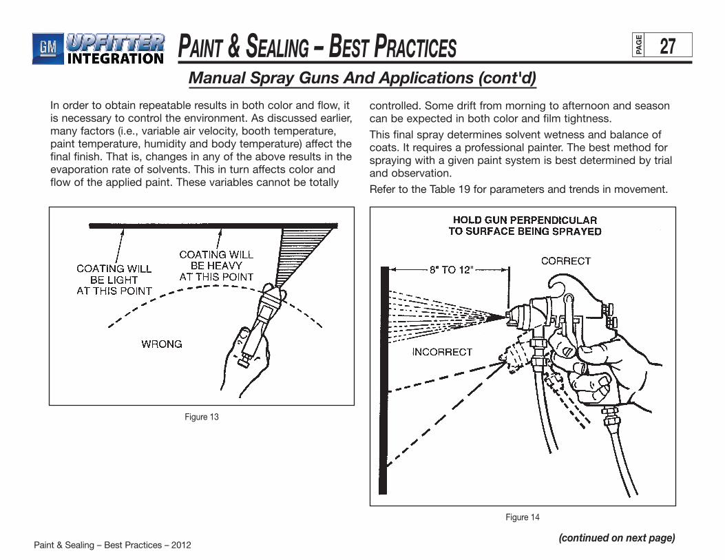
In order to obtain repeatable results in both color and flow, it is necessary to control the environment. As discussed earlier, many factors (i.e., variable air velocity, booth temperature, paint temperature, humidity and body temperature) affect the final finish. That is, changes in any of the above results in the evaporation rate of solvents. This in turn affects color and flow of the applied paint. These variables cannot be totally
controlled. Some drift from morning to afternoon and seasoncan be expected in both color and film tightness.
This final spray determines solvent wetness and balance of coats. It requires a professional painter. The best method for spraying with a given paint system is best determined by trial and observation.
Refer to the Table 19 for parameters and trends in movement.
Figure 13
Figure 14
Paint & Sealing – Best Practices – 2012
Paint & Sealing – BeSt PracticeS 28PAG
E
(continued on next page)
Manual Spray Guns And Applications (cont'd)
Figure 15Table 19 – Table Of Parameters/Trends In Movement
1. Gun distance* Increase distance Decrease distance
— Lowers transfer efficiency; drier paint film. lighter color— Raises transfer efficiency; wetting paint film, darker color
2. Fluid deliveries* Increase fluid Decrease fluid
— Raises transfer efficiency; drier film, lighter color— Lowers transfer efficiency; drier film, lighter color
3. Air pressure* Raise air Lower air
— Lower transfer efficiency; drier film, lighter color— Higher transfer efficiency; wetter film, darker color
— More flow, darker color, excessive film could wet back second coat coat and mottle.
— More orange peel, lighter color too dry, could cause lack of fusion between coats, resulting in blotchy color.
— Darker color, excessive second coat could mottle.— Lighter color, insufficient film-build to cover first coat could result in
blotchy color.
4. Coat split-up first coat — wetter
First coat — drier and/or less film
Second coat — wetter and/or more film Second coat — drier and/or less film
Paint & Sealing – Best Practices – 2012
Paint & Sealing – BeSt PracticeS 29PAG
E
(continued on next page)
Manual Spray Guns And Applications (cont'd)
Figure 16
Solvent Rub Testing Of CoatsUse the solvent rub test to determine if the paint film is properly cured. This specification provides the proper procedures for conducting solvent rub testing on organic coatings. See Appendix I of this manual for correct solvent for use with a particular coating. Complete air dry systems may require 72 hours or more to achieve cure necessary to passthis test.
Solvent Wipe ProcedureFollow these steps when performing a solvent rub test:
• Selectrepresentativesampleforevaluation.
• Soakasmallclothwiththeappropriatesolvent.Squeezeout excess.
• Usingforefingeranda1-to2-inchback-and-forthmotion,apply 10 double rubs. (One complete back-and-forth motion equals one double rub.) Apply firm pressure (ideally, enough to produce a squeaking sound) while rubbing.
• Inspectthepaintsurfaceforanychanges.Itmayalsohelpto examine the cloth for paint residue. Use Table 20 (below) to assign a rating.
Rating Paint Surface Paint Residue on Cloth0 No change None
1 Slight – barely observable Trace amount
3 Moderate – readily noticeable Readily noticeable
5 Severe – very obvious Saturated with color
Table 20 – Solvent Rub Test Ratings
Paint & Sealing – Best Practices – 2012
Paint & Sealing – BeSt PracticeS 30PAG
E
Transit CoatingThis section briefly outlines key characteristics of transit coating materials required for all export vehicles. See GM specifications 9982223 and 9982224 for specific product details.
Apply acrylic water-based sprayable air-dry transit coating (9982223) by air-atomized spray.
• TypicalV.O.C.is00-1.0lb.V.O.C./gallon
• Typicalvolumesolidis22%
• Applicationparametersare:
— Spray to 0.2-0.4 mil. (0.3 target) to match approved appearance panel.
— Spray all horizontal surfaces (shippable vehicles only).
— Transit coating must air dry within one minute. Forced air or infrared (IR) may be used.
Transit coating must be removable by amine solution (9982224) produced by same supplier.
PropertiesThe specification in Appendix I outlines the key process controls for acrylic water-based sprayable air-dry transit
• dilution
• atomizingair
• fluidflow
• gunspeedanddistance
• ambientairtemperature
• relativehumidity
All parameters must be adjusted to allow for uncontrollable variances in temperature and humidity. A highly atomized application of transit coating is necessary to decrease air-dry time, but the coating must also completely “knit” together to form one uniform coating.
A properly applied transit coating is uniform in film-build and resembles a dull, hazy paint finish. When dry, the coating is hard and retains no tackiness. An inconsistent or low film-build reduces the level of protection against penetration of any foreign material. Heavy film-build does not usually significantly increase the protection level provided by normal film-builds. It does, however, increase the difficulty in removing the coating and may actually result in a hazed paint surface beneath the coating. Hazing can be attributed to transit coating residue that cannot be removed.
Remove transit coatings with amine solutions that are alkaline but nonhazardous and available for manual use.
Appendix I
(continued on next page)
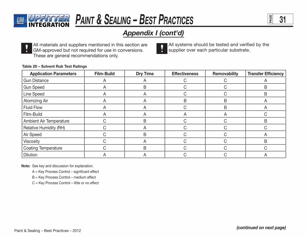
Paint & Sealing – Best Practices – 2012
Paint & Sealing – BeSt PracticeS 31PAG
E
(continued on next page)
Appendix I (cont'd)
All materials and suppliers mentioned in this section are GM-approved but not required for use in conversions. These are general recommendations only.
All systems should be tested and verified by the supplier over each particular substrate.
Application Parameters Film-Build Dry Time Effectiveness Removability Transfer EfficiencyGun Distance A A C C A
Gun Speed A B C C B
Line Speed A A C C B
Atomizing Air A A B B A
Fluid Flow A A C B A
Film-Build A A A A C
Ambient Air Temperature C B C C B
Relative Humidity (RH) C A C C C
Air Speed C B C C A
Viscosity C A C C B
Coating Temperature C B C C C
Dilution A A C C A
Table 20 – Solvent Rub Test Ratings
Note: See key and discussion for explanation.
A = Key Process Control – significant effect
B = Key Process Control – medium effect
C = Key Process Control – little or no effect
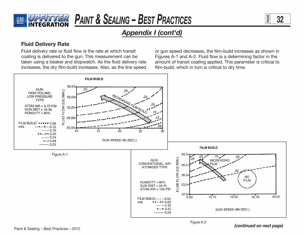
Paint & Sealing – Best Practices – 2012
Paint & Sealing – BeSt PracticeS 32PAG
E
(continued on next page)
Appendix I (cont'd)
Fluid Delivery RateFluid delivery rate or fluid flow is the rate at which transit coating is delivered to the gun. This measurement can be taken using a beaker and stopwatch. As the fluid delivery rate increases, the dry film-build increases. Also, as the line speed
or gun speed decreases, the film-build increases as shown in Figures A-1 and A-2. Fluid flow is a determining factor in the amount of transit coating applied. This parameter is critical to film-build, which in turn is critical to dry time.
Figure A-2
Figure A-1
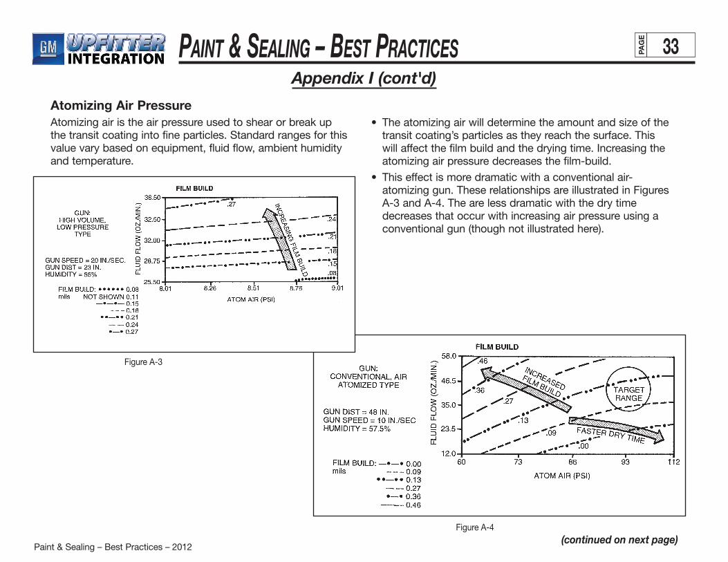
Paint & Sealing – Best Practices – 2012
Paint & Sealing – BeSt PracticeS 33PAG
E
(continued on next page)
Appendix I (cont'd)
Atomizing Air PressureAtomizing air is the air pressure used to shear or break up the transit coating into fine particles. Standard ranges for this value vary based on equipment, fluid flow, ambient humidity and temperature.
• Theatomizingairwilldeterminetheamountandsizeofthetransit coating’s particles as they reach the surface. This will affect the film build and the drying time. Increasing the atomizing air pressure decreases the film-build.
• Thiseffectismoredramaticwithaconventionalair-atomizing gun. These relationships are illustrated in Figures A-3 and A-4. The are less dramatic with the dry time decreases that occur with increasing air pressure using a conventional gun (though not illustrated here).
Figure A-4
Figure A-3
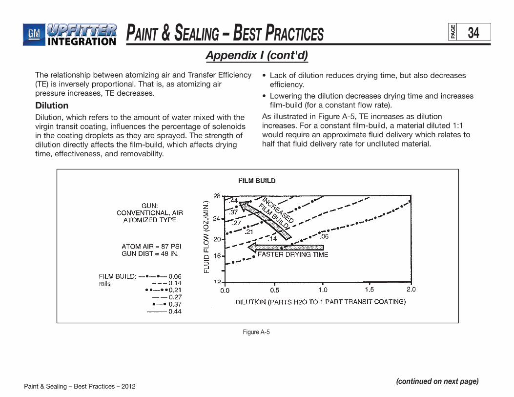
Paint & Sealing – Best Practices – 2012
Paint & Sealing – BeSt PracticeS 34PAG
E
Appendix I (cont'd)
Figure A-5
(continued on next page)
The relationship between atomizing air and Transfer Efficiency (TE) is inversely proportional. That is, as atomizing air pressure increases, TE decreases.
DilutionDilution, which refers to the amount of water mixed with the virgin transit coating, influences the percentage of solenoids in the coating droplets as they are sprayed. The strength of dilution directly affects the film-build, which affects dryingtime, effectiveness, and removability.
• Lackofdilutionreducesdryingtime,butalsodecreasesefficiency.
• Loweringthedilutiondecreasesdryingtimeandincreasesfilm-build (for a constant flow rate).
As illustrated in Figure A-5, TE increases as dilution increases. For a constant film-build, a material diluted 1:1 would require an approximate fluid delivery which relates to half that fluid delivery rate for undiluted material.
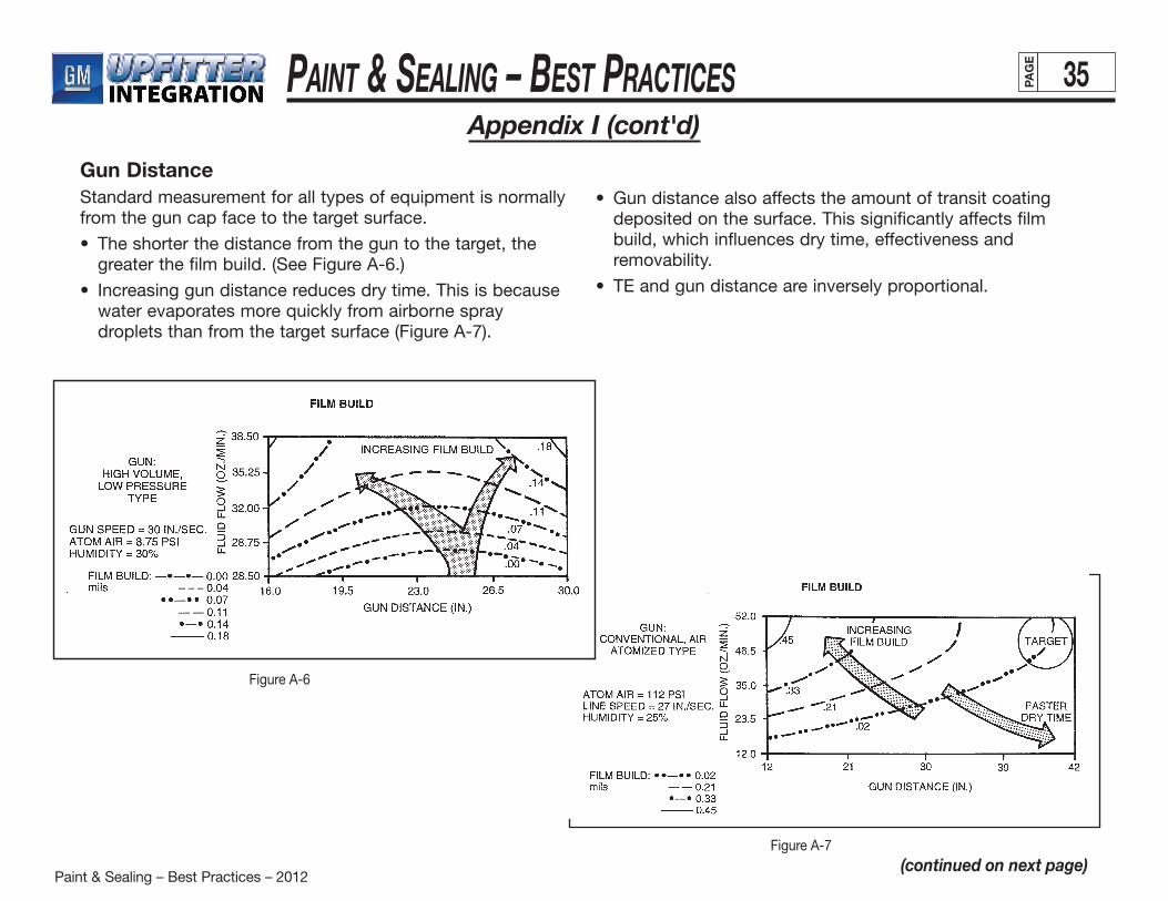
Paint & Sealing – Best Practices – 2012
Paint & Sealing – BeSt PracticeS 35PAG
E
Appendix I (cont'd)
(continued on next page)
Gun DistanceStandard measurement for all types of equipment is normally from the gun cap face to the target surface.
• Theshorterthedistancefromtheguntothetarget,thegreater the film build. (See Figure A-6.)
• Increasinggundistancereducesdrytime.Thisisbecausewater evaporates more quickly from airborne spray droplets than from the target surface (Figure A-7).
• Gundistancealsoaffectstheamountoftransitcoatingdeposited on the surface. This significantly affects film build, which influences dry time, effectiveness and removability.
• TEandgundistanceareinverselyproportional.
Figure A-7
Figure A-6
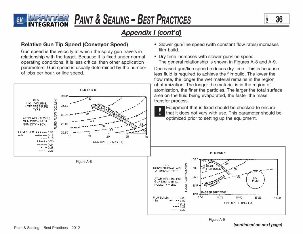
Paint & Sealing – Best Practices – 2012
Paint & Sealing – BeSt PracticeS 36PAG
E
Appendix I (cont'd)
(continued on next page)
Relative Gun Tip Speed (Conveyor Speed)Gun speed is the velocity at which the spray gun travels in relationship with the target. Because it is fixed under normal operating conditions, it is less critical than other application parameters. Gun speed is usually determined by the number of jobs per hour, or line speed.
• Slowergun/linespeed(withconstantflowrates)increasesfilm-build.
• Drytimeincreaseswithslowergun/linespeed. The general relationship is shown in Figures A-8 and A-9.
Decreased gun/line speed reduces dry time. This is because less fluid is required to achieve the filmbuild. The lower the flow rate, the longer the wet material remains in the region of atomization. The longer the material is in the region of atomization, the finer the particles. The larger the total surface area on the fluid being evaporated, the faster the mass transfer process.
Equipment that is fixed should be checked to ensure that it does not vary with use. This parameter should be optimized prior to setting up the equipment.
Figure A-9
Figure A-8
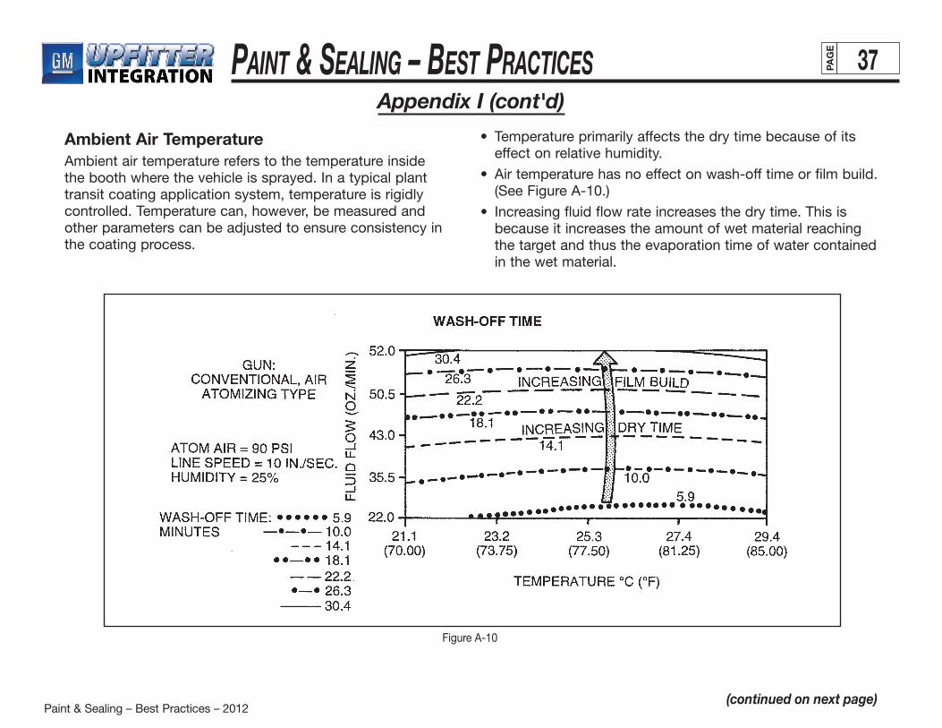
Paint & Sealing – Best Practices – 2012
Paint & Sealing – BeSt PracticeS 37PAG
E
Appendix I (cont'd)
(continued on next page)
Ambient Air TemperatureAmbient air temperature refers to the temperature inside the booth where the vehicle is sprayed. In a typical plant transit coating application system, temperature is rigidly controlled. Temperature can, however, be measured and other parameters can be adjusted to ensure consistency in the coating process.
• Temperatureprimarilyaffectsthedrytimebecauseofitseffect on relative humidity.
• Airtemperaturehasnoeffectonwash-offtimeorfilmbuild.(See Figure A-10.)
• Increasingfluidflowrateincreasesthedrytime.Thisisbecause it increases the amount of wet material reaching the target and thus the evaporation time of water contained in the wet material.
Figure A-10
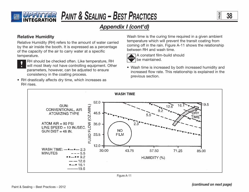
Paint & Sealing – Best Practices – 2012
Paint & Sealing – BeSt PracticeS 38PAG
E
Appendix I (cont'd)
(continued on next page)
Figure A-11
Relative HumidityRelative Humidity (RH) refers to the amount of water carried by the air inside the booth. It is expressed as a percentage of the capacity of the air to carry water at a specific temperature.
RH should be checked often. Like temperature, RH will most likely not have controlling equipment. Other parameters, however, can be adjusted to ensure consistency in the coating process.
• RHdrasticallyaffectsdrytime,whichincreasesas RH rises.
Wash time is the curing time required in a given ambient temperature which will prevent the transit coating from coming off in the rain. Figure A-11 shows the relationship between RH and wash time.
A constant film-build should be maintained.
• Washtimeisincreasedbybothincreasedhumidityandincreased flow rate. This relationship is explained in the previous section.
CAUTION
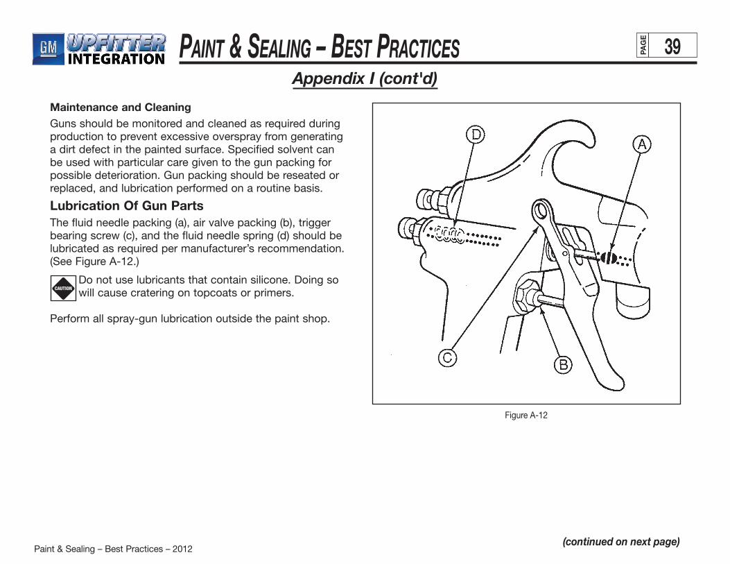
Paint & Sealing – Best Practices – 2012
Paint & Sealing – BeSt PracticeS 39PAG
E
Appendix I (cont'd)
(continued on next page)
Maintenance and CleaningGuns should be monitored and cleaned as required during production to prevent excessive overspray from generating a dirt defect in the painted surface. Specified solvent can be used with particular care given to the gun packing for possible deterioration. Gun packing should be reseated or replaced, and lubrication performed on a routine basis.
Lubrication Of Gun PartsThe fluid needle packing (a), air valve packing (b), trigger bearing screw (c), and the fluid needle spring (d) should be lubricated as required per manufacturer’s recommendation. (See Figure A-12.)
Do not use lubricants that contain silicone. Doing so will cause cratering on topcoats or primers.
Perform all spray-gun lubrication outside the paint shop.
CAUTION
Figure A-12
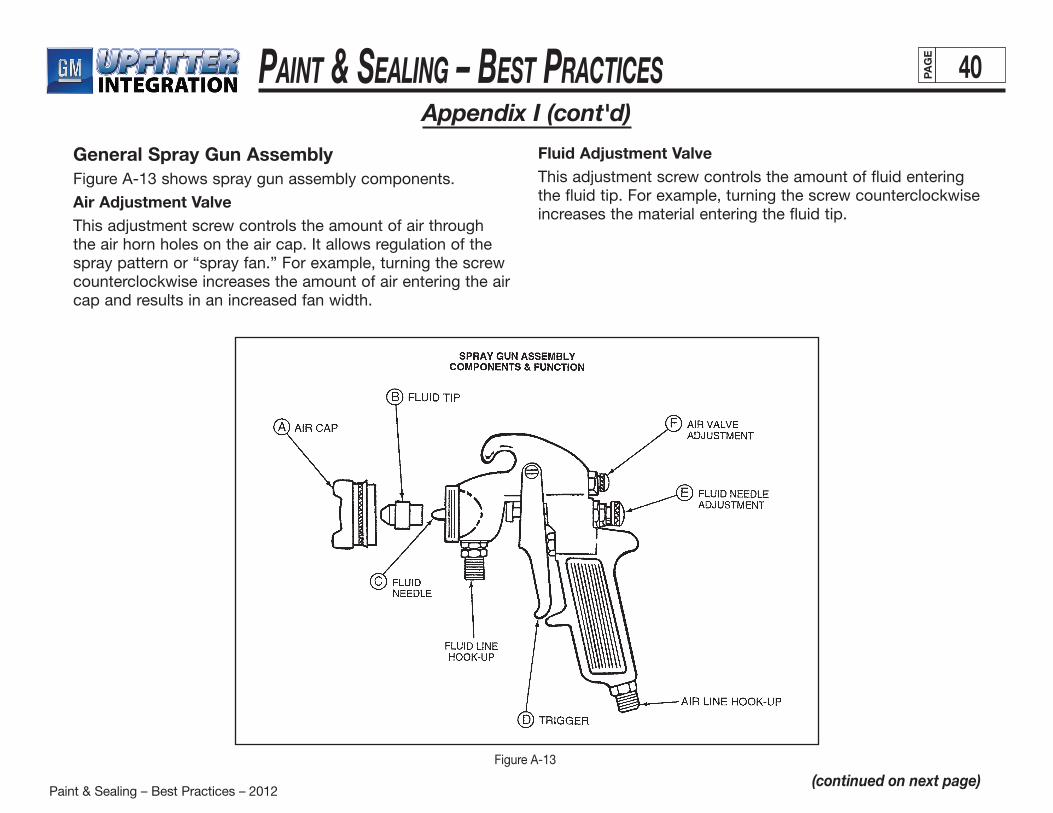
Paint & Sealing – Best Practices – 2012
Paint & Sealing – BeSt PracticeS 40PAG
E
Appendix I (cont'd)
(continued on next page)
General Spray Gun AssemblyFigure A-13 shows spray gun assembly components.
Air Adjustment ValveThis adjustment screw controls the amount of air through the air horn holes on the air cap. It allows regulation of the spray pattern or “spray fan.” For example, turning the screw counterclockwise increases the amount of air entering the air cap and results in an increased fan width.
Fluid Adjustment ValveThis adjustment screw controls the amount of fluid entering the fluid tip. For example, turning the screw counterclockwise increases the material entering the fluid tip.
Figure A-13
Paint & Sealing – Best Practices – 2012
Paint & Sealing – BeSt PracticeS 41PAG
E
Appendix II
(continued on next page)
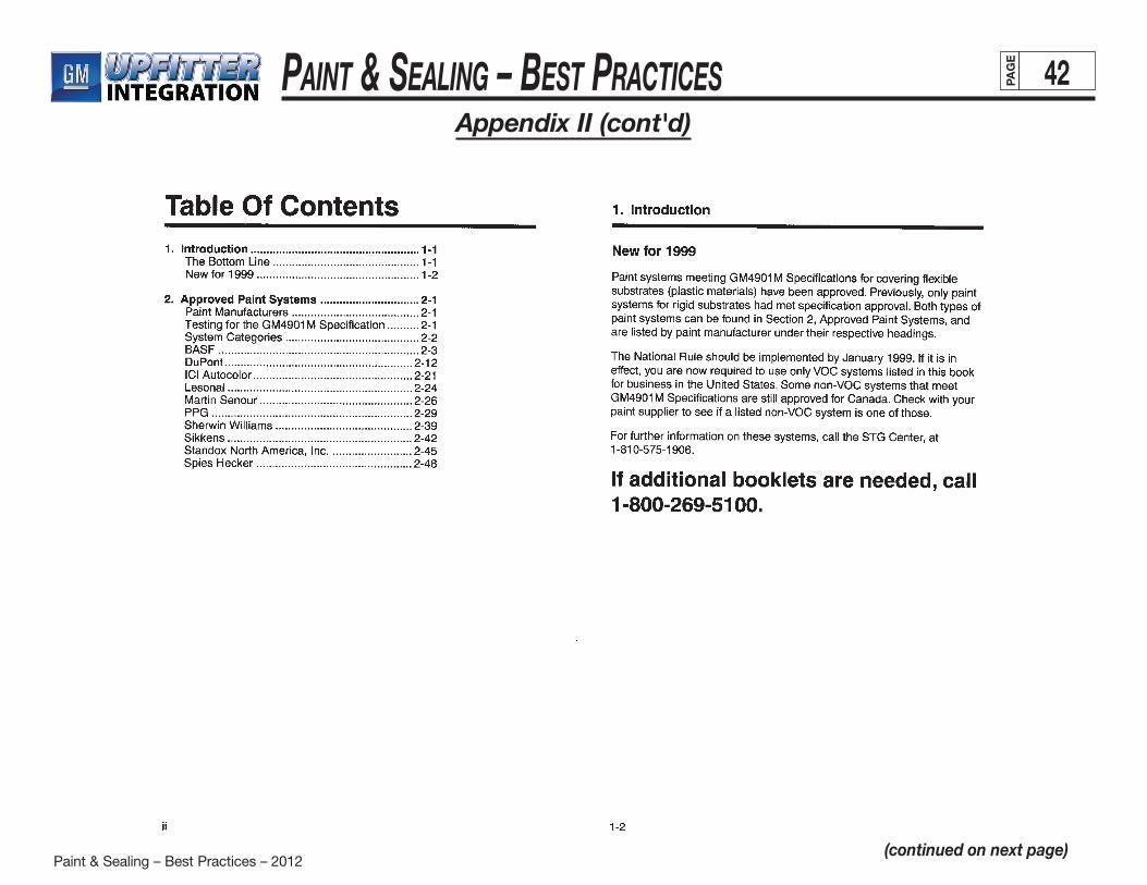
Paint & Sealing – Best Practices – 2012
Paint & Sealing – BeSt PracticeS 42PAG
E
Appendix II (cont'd)
(continued on next page)
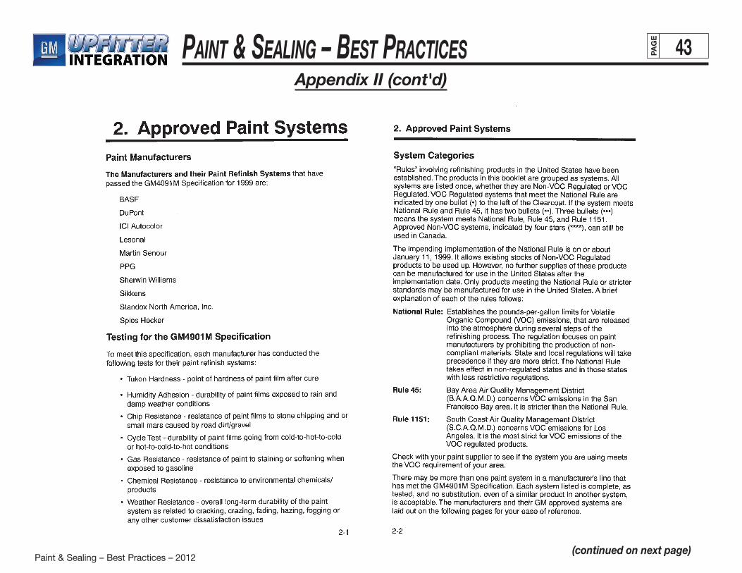
Paint & Sealing – Best Practices – 2012
Paint & Sealing – BeSt PracticeS 43PAG
E
Appendix II (cont'd)
(continued on next page)
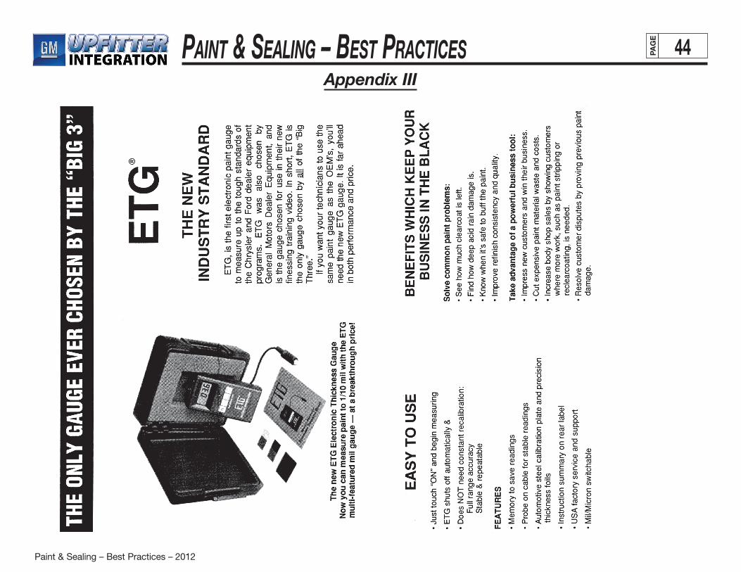
Paint & Sealing – Best Practices – 2012
Paint & Sealing – BeSt PracticeS 44PAG
E
Appendix III