Embed Size (px)
Citation preview
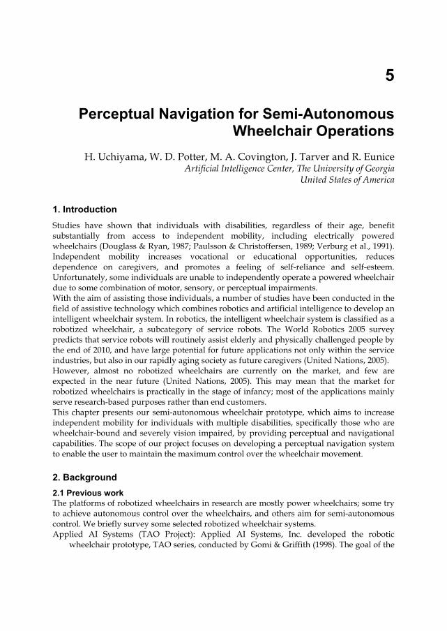
5
Perceptual Navigation for Semi-Autonomous Wheelchair Operations
H. Uchiyama, W. D. Potter, M. A. Covington, J. Tarver and R. Eunice Artificial Intelligence Center, The University of Georgia
United States of America
1. Introduction Studies have shown that individuals with disabilities, regardless of their age, benefit substantially from access to independent mobility, including electrically powered wheelchairs (Douglass & Ryan, 1987; Paulsson & Christoffersen, 1989; Verburg et al., 1991). Independent mobility increases vocational or educational opportunities, reduces dependence on caregivers, and promotes a feeling of self-reliance and self-esteem. Unfortunately, some individuals are unable to independently operate a powered wheelchair due to some combination of motor, sensory, or perceptual impairments. With the aim of assisting those individuals, a number of studies have been conducted in the field of assistive technology which combines robotics and artificial intelligence to develop an intelligent wheelchair system. In robotics, the intelligent wheelchair system is classified as a robotized wheelchair, a subcategory of service robots. The World Robotics 2005 survey predicts that service robots will routinely assist elderly and physically challenged people by the end of 2010, and have large potential for future applications not only within the service industries, but also in our rapidly aging society as future caregivers (United Nations, 2005). However, almost no robotized wheelchairs are currently on the market, and few are expected in the near future (United Nations, 2005). This may mean that the market for robotized wheelchairs is practically in the stage of infancy; most of the applications mainly serve research-based purposes rather than end customers. This chapter presents our semi-autonomous wheelchair prototype, which aims to increase independent mobility for individuals with multiple disabilities, specifically those who are wheelchair-bound and severely vision impaired, by providing perceptual and navigational capabilities. The scope of our project focuses on developing a perceptual navigation system to enable the user to maintain the maximum control over the wheelchair movement.
2. Background 2.1 Previous work The platforms of robotized wheelchairs in research are mostly power wheelchairs; some try to achieve autonomous control over the wheelchairs, and others aim for semi-autonomous control. We briefly survey some selected robotized wheelchair systems. Applied AI Systems (TAO Project): Applied AI Systems, Inc. developed the robotic
wheelchair prototype, TAO series, conducted by Gomi & Griffith (1998). The goal of the
Service Robot Applications
72
TAO project is to create an add-on system for any standard powered wheelchair that will provide a high level of autonomy. The current model presented to the market is TAO-7 and is mostly used for research and development purposes.1
Kiss Institute of Practical Robotics (Tin Man Project): The Tin Man project is aimed at the development of a low-cost robotic wheelchair to aid people with impaired mobility while focusing on a more user-friendly interface and cost issues (Miller & Slack, 1995). The latest version, Tin Man II, is a robotized wheelchair which exhibits manual navigation with obstacle avoidance override, autonomous control, and manual mode. The Tin Man system was also used as a base platform for the Wheelesley project at MIT (see below).
MIT Artificial Intelligence Lab (Wheelesley): The goal of the Wheelesley project is the creation of a complete robotic wheelchair system to be used by users unable to manipulate a standard motorized wheelchair. This project aims to establish the system for both indoor and outdoor navigation with automatically switching navigation modes. Wheelesley was developed based on the Tin Man model and interacts with the seated user via a graphical user interface (Yanco, 1998).
Northeastern University, Deictically Controlled Wheelchair: The goal of this project is to create a “gopher” robot that can be given commands easily and accurately for the handicapped (Crisman & Cleary, 1998). The robot will retrieve objects in the environment autonomously via commands from users, which are communicated deictically.
University of Edinburgh (Smart Wheelchair): The CALL Centre of the University of Edinburgh has developed a wheelchair intended to be used by children who do not have the physical, perceptual or cognitive abilities to control an ordinary powered mobility aid (Odor & Watson, 1994).2 The Smart Wheelchair exhibits collision detection followed by a maneuvering action, follows line tracks laid along the floor, and communicates with the user via a speech synthesizer or other feedback system.
University of Michigan (NavChair): The NavChair system intends to provide mobility support to users who are unable to drive standard motorized wheelchairs, and this is one of the most successful systems in the ’90s (Levine et al., 1999). The NavChair uses several navigation modes and switches among them automatically. The navigation modes are as follows: general obstacle avoidance, door passage, and wall following.
While there has been much research to develop robotized wheelchairs, very few are sold commercially, such as Applied AI and CALL Centre, and none of those systems are intended to be used outside of a research lab or a training facility.
2.2 Semi-autonomous wheelchairs With autonomous control, the system probes the environment, makes decisions, and fully controls the mobility of the wheelchair, which leaves the user totally dependent upon the equipment. While some users may be comfortable with an autonomous wheelchair transportation system, others want to be more involved with the process. It is essential for
1 Information is available at http://www.aai.ca 2 Information is available at http://callcentre.education.ed.ac.uk/
Perceptual Navigation for Semi-Autonomous Wheelchair Operations
73
them to feel in control, while being responsible for both decision-making and motion rather than being a passenger. A semi-autonomous (SA) wheelchair system comprises hardware equipment similar to autonomous wheelchairs, but the purpose of the system development focuses on maximizing the level of autonomy of users. Thus, the magnitude of assistance is designed to provide just as much as the user really needs. Generally, the type of assistance for a user varies from one to another; therefore, the specification of an SA wheelchair system needs to be determined based on the user’s physical capabilities. A number of research projects have developed various types of semi-autonomous wheelchairs. Borgolte et al. (1998) developed a robotized wheelchair featuring omnidirectional maneuverability to provide an intuitive semi-autonomous control system to assist people with severe or multiple disabilities. Argyros et al. (2002) presented a robotic wheelchair with a semi-autonomous navigation system comprising a panoramic vision system to support the users who have limited motor control of the upper extremities. The Mobile Internet Connected Assistant (MICA) project (Rönnbäck et al., 2006) designed a semi-autonomous wheelchair system in which the user either locally or remotely controls the chair by means of head-held sensors. Despite using a slightly different platform, a power-assisted manual wheelchair,3 Simpson et al. (2005) demonstrated the first prototype which attempts to provide the users who have visual impairments with some basic navigation tasks such as collision avoidance. However, none of these systems provide or enhance perceptual capabilities for the seated user who has severe visual impairment.
2.3 Motivation As stated in Section 1, the goal of our project is to increase the independent mobility of power wheelchair users with severe visual impairment by providing perceptual and navigational capabilities. We assume our typical SA wheelchair user is tactilely and audibly competent with fine motor control of the upper extremities. In fact, our research efforts have been influenced by a former student who has exactly the disabilities we are mentioning. A collaborative discussion with the student at the initial stage of the project enabled us to elucidate such problems of interest as: collision avoidance, human and obstacle detection, drop-off avoidance, portal navigation, textual-information acquisition, and indoor navigation. Many large universities provide on-campus curb-to-curb van transportation service to persons with mobility, visual, and other health-related impairments; however, typically no official care attendant service is provided inside a building. Therefore our focus is primarily on the situations in which the wheelchair users need to be on their own, independently maneuvering in indoor circumstances.
3. Design In this section, we present an overview of our behavior-based architecture with Behavior Cell and Behavior Network components, and hardware design which consists of a sensor system and feedback module. 3 Based on a manual wheelchair, the rear wheel hubs are replaced with motorized ones that magnify and/or adjust the propulsive force provided by the user.
Service Robot Applications
74
3.1 Behavior based approach Since the SA wheelchair system needs to be individualized to the user, our design principle is based upon modularity and flexibility. Further, due to the nature of the problems described in Section 2.3 which must be resolved quickly and handled concurrently, the behavior-based control (BBC) architecture (Arkin, 1998; Brooks, 1991; Matarić, 1992) is suitable for the base architecture of our design. Utilizing a customized BBC architecture, we define behaviors which emerge from an agent-environment interaction based on a number of loosely tied processes that run asynchronously and respond to problems in a parallel manner. In our project, those behaviors are realized to accomplish their tasks through user-machine cooperation. We call the robotic wheelchair a wheelchair-navigation agent. The wheelchair-navigation agent consists of two cooperating sub-agents: the perceptual agent and the navigational agent. The perceptual agent acquires the state of the environment through sensors (Perceptual Behaviors), and the navigational agent interprets the state and passes the appropriate information to the user (Navigational Behaviors). Finally the user manipulates the wheelchair in combination with his/her own perception and judgment (Manipulative Behaviors). Since we intend to leave maximum control on the user side, the degree of mobility assistance from the wheelchair-navigation agent is set to minimal; that is, the system does not directly intervene in controlling the wheelchair at all. We also assume that our target users are able to generate an internal representation (cognitive map) of the familiar environment; that is, they have some knowledge of the starting or current location and the destination as well as some landmarks in between. Based on such assumptions, assisting local navigation, including obstacle avoidance, and landmark matching are more immediately needed tasks than more complicated tasks, such as planning the whole path and navigating autonomously. The main focus of our project is on pursuing perceptual and navigational assistance, thus semi-autonomous control.
3.1.1 Behavior cell We present a unit of the behavioral structure, a Behavior Cell, which is based upon the BBC architecture with an extended input/output feature. A Behavior Cell consists of an input/output (I/O) component, a behavioral function component, and an internal storage component (Figure 1). It structurally resembles an artificial neuron; however, it has a logical gate in addition to widely extended functions such that the innervation link between cells can run by both Boolean and numeric means. A Behavior Cell does not have to employ all components; it may or may not contain the behavioral function and the internal storage components depending upon what features it needs. Behavior cells communicate with other Behavior Cells, sensors, and effectors through their I/O components. The I/O component consists of a subset of the following eight I/O ports: Port-EB, excitatory inputs; Port-IB, inhibitory inputs; Port-DI, sensory/behavioral inputs; Port-RS, a reset signal; Port-IS, an innervation signal; Port-AB, an activation output; Port-EO, an effect output; and Port-AO, actuator outputs. The excitatory and inhibitory inputs are linked to the corresponding behaviors’ activation output ports. When any activation (inhibition) conditions are met, the behavior is activated (deactivated). Our architecture allows both Port-EB and Port-IB to specify activation (inhibition) conditions by using logical expressions (Boolean algebraic functions), such as Activation = (Activation1 ∧ Activation2) ∨ Activation3.
Perceptual Navigation for Semi-Autonomous Wheelchair Operations
75
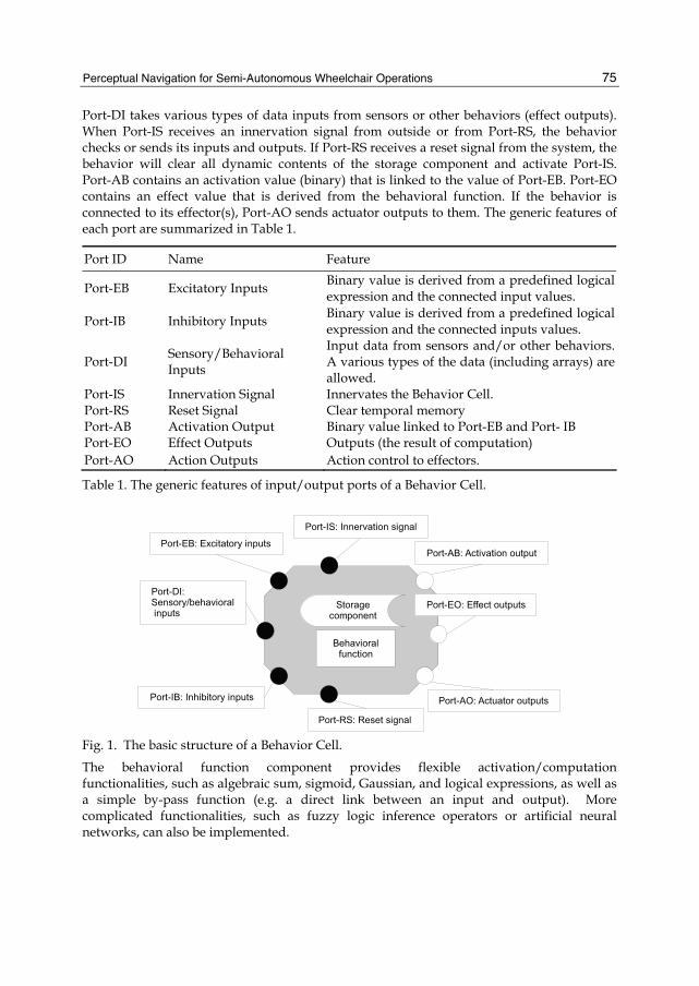
Port-DI takes various types of data inputs from sensors or other behaviors (effect outputs). When Port-IS receives an innervation signal from outside or from Port-RS, the behavior checks or sends its inputs and outputs. If Port-RS receives a reset signal from the system, the behavior will clear all dynamic contents of the storage component and activate Port-IS. Port-AB contains an activation value (binary) that is linked to the value of Port-EB. Port-EO contains an effect value that is derived from the behavioral function. If the behavior is connected to its effector(s), Port-AO sends actuator outputs to them. The generic features of each port are summarized in Table 1.
Port ID Name Feature
Port-EB Excitatory Inputs Binary value is derived from a predefined logical expression and the connected input values.
Port-IB Inhibitory Inputs Binary value is derived from a predefined logical expression and the connected inputs values.
Port-DI Sensory/Behavioral Inputs
Input data from sensors and/or other behaviors. A various types of the data (including arrays) are allowed.
Port-IS Innervation Signal Innervates the Behavior Cell. Port-RS Reset Signal Clear temporal memory Port-AB Activation Output Binary value linked to Port-EB and Port- IB Port-EO Effect Outputs Outputs (the result of computation) Port-AO Action Outputs Action control to effectors.
Table 1. The generic features of input/output ports of a Behavior Cell.
Fig. 1. The basic structure of a Behavior Cell.
The behavioral function component provides flexible activation/computation functionalities, such as algebraic sum, sigmoid, Gaussian, and logical expressions, as well as a simple by-pass function (e.g. a direct link between an input and output). More complicated functionalities, such as fuzzy logic inference operators or artificial neural networks, can also be implemented.
Service Robot Applications
76
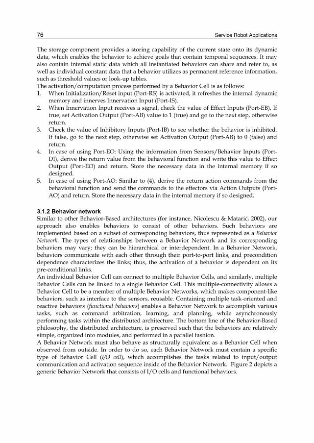
The storage component provides a storing capability of the current state onto its dynamic data, which enables the behavior to achieve goals that contain temporal sequences. It may also contain internal static data which all instantiated behaviors can share and refer to, as well as individual constant data that a behavior utilizes as permanent reference information, such as threshold values or look-up tables. The activation/computation process performed by a Behavior Cell is as follows: 1. When Initialization/Reset input (Port-RS) is activated, it refreshes the internal dynamic
memory and innerves Innervation Input (Port-IS). 2. When Innervation Input receives a signal, check the value of Effect Inputs (Port-EB). If
true, set Activation Output (Port-AB) value to 1 (true) and go to the next step, otherwise return.
3. Check the value of Inhibitory Inputs (Port-IB) to see whether the behavior is inhibited. If false, go to the next step, otherwise set Activation Output (Port-AB) to 0 (false) and return.
4. In case of using Port-EO: Using the information from Sensors/Behavior Inputs (Port-DI), derive the return value from the behavioral function and write this value to Effect Output (Port-EO) and return. Store the necessary data in the internal memory if so designed.
5. In case of using Port-AO: Similar to (4), derive the return action commands from the behavioral function and send the commands to the effectors via Action Outputs (Port-AO) and return. Store the necessary data in the internal memory if so designed.
3.1.2 Behavior network Similar to other Behavior-Based architectures (for instance, Nicolescu & Matarić, 2002), our approach also enables behaviors to consist of other behaviors. Such behaviors are implemented based on a subset of corresponding behaviors, thus represented as a Behavior Network. The types of relationships between a Behavior Network and its corresponding behaviors may vary; they can be hierarchical or interdependent. In a Behavior Network, behaviors communicate with each other through their port-to-port links, and precondition dependence characterizes the links; thus, the activation of a behavior is dependent on its pre-conditional links. An individual Behavior Cell can connect to multiple Behavior Cells, and similarly, multiple Behavior Cells can be linked to a single Behavior Cell. This multiple-connectivity allows a Behavior Cell to be a member of multiple Behavior Networks, which makes component-like behaviors, such as interface to the sensors, reusable. Containing multiple task-oriented and reactive behaviors (functional behaviors) enables a Behavior Network to accomplish various tasks, such as command arbitration, learning, and planning, while asynchronously performing tasks within the distributed architecture. The bottom line of the Behavior-Based philosophy, the distributed architecture, is preserved such that the behaviors are relatively simple, organized into modules, and performed in a parallel fashion. A Behavior Network must also behave as structurally equivalent as a Behavior Cell when observed from outside. In order to do so, each Behavior Network must contain a specific type of Behavior Cell (I/O cell), which accomplishes the tasks related to input/output communication and activation sequence inside of the Behavior Network. Figure 2 depicts a generic Behavior Network that consists of I/O cells and functional behaviors.
Perceptual Navigation for Semi-Autonomous Wheelchair Operations
77
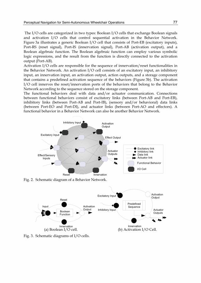
The I/O cells are categorized in two types: Boolean I/O cells that exchange Boolean signals and activation I/O cells that control sequential activation in the Behavior Network. Figure 3a illustrates a generic Boolean I/O cell that consists of Port-EB (excitatory inputs), Port-RS (reset signal), Port-IS (innervation signal), Port-AB (activation output), and a Boolean algebraic function. The Boolean algebraic function can employ various symbolic logic expressions, and the result from the function is directly connected to the activation output (Port-AB). Activation I/O cells are responsible for the sequence of innervation/reset functionalities in the Behavior Network. An activation I/O cell consists of an excitatory input, an inhibitory input, an innervation input, an activation output, action outputs, and a storage component that contains a predefined activation sequence of the behaviors (Figure 3b). The activation I/O cell innerves the reset/innervation ports of the behaviors that belong to the Behavior Network according to the sequence stored on the storage component. The functional behaviors deal with data and/or actuator communication. Connections between functional behaviors consist of excitatory links (between Port-AB and Port-EB), inhibitory links (between Port-AB and Port-IB), (sensory and/or behavioral) data links (between Port-EO and Port-DI), and actuator links (between Port-AO and effectors). A functional behavior in a Behavior Network can also be another Behavior Network.
Fig. 2. Schematic diagram of a Behavior Network.
(a) Boolean I/O cell. (b) Activation I/O Cell.
Fig. 3. Schematic diagrams of I/O cells.

Service Robot Applications
78
Fig. 4. Schematic diagram of I/O cell links in a Behavior Network. However, the activation process of a Behavior Network differs from the one of a Behavior Cell. An Innervation cell is first innerved and it innervates the Excitatory Inputs cell, Inhibitory Inputs cell, and Activation Output cell in this order. If the value of Port-AO (activation output) of an Activation Output cell is true, it will innervate the functional behaviors in a predefined order otherwise the whole process will return; thus the Behavior Network will be deactivated (Figure 4).
3.2 Sensor system In this research, we design and employ a sensor system which consists of three types of modules: a stationary ranging module, a motorized vision module, and a motion sensing module. The stationary ranging module is attached to the wheelchair and constantly measures distances to any objects that are within the scope of the sensors. The motorized vision module is designed to have the ability to pan/tilt and to acquire depth data as well as scenery images, so that the perceptual behaviors can utilize more detailed information. The motion sensing module consists of a gyroscope and accelerometers and continuously tracks the position, orientation, and velocity of the wheelchair.
3.2.1 Stationary ranging module Employing ultrasonic range sensors (sonar sensors) for the stationary ranging module appears appropriate because sonar sensors commonly used in robotics research have an effective range (typically between a few centimeters and 6 m) that is suitable for indoor navigation. Sonar sensors are also inexpensive and easy to install. We chose to employ Devantech SRF08 because of its cost-perfomance and size efficiency. The specification of the SRF08 and its beam pattern are shown in Figure 5.4 According to the specification, the ultrasound wave propagation profile (beam width) of an SRF08 is roughly 45°. It is common to employ an array of sensors in order to obtain a wide coverage area around a mobile robot (specifically for omni-directional robots). However, the wheelchair we employed is kinetically non-holonomic; that is, although it could physically move laterally, it is not equipped with the mechanism to control such movement. Based on the kinetic
4 Retrieved from http://www.acroname.com
Perceptual Navigation for Semi-Autonomous Wheelchair Operations
79
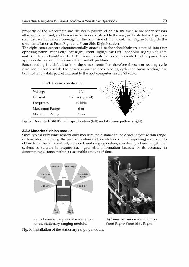
property of the wheelchair and the beam pattern of an SRF08, we use six sonar sensors attached to the front, and two sonar sensors are placed to the rear, as illustrated in Figure 6a such that we have more coverage on the front side of the wheelchair. Figure 6b depicts the sonar installation at Front Right and Front-Side Right location. The eight sonar sensors circumferentially attached to the wheelchair are coupled into four opposing pairs: Front Left/Rear Right, Front Right/Rear Left, Front-Side Right/Side Left, and Side Right/Front-Side Left. The sensor controller is implemented to fire pairs at an appropriate interval to minimize the crosstalk problem. Sonar reading is a default task on the sensor controller, therefore the sensor reading cycle runs continuously while the power is on. On each reading cycle, the sonar readings are bundled into a data packet and sent to the host computer via a USB cable.
SRF08 main specification
Voltage 5 V Current 15 mA (typical) Frequency 40 kHz Maximum Range 6 m Minimum Range 3 cm
Fig. 5. Devantech SRF08 main specification (left) and its beam pattern (right).
3.2.2 Motorized vision module Since typical ultrasonic sensors only measure the distance to the closest object within range, certain information (e.g. the precise location and orientation of a door-opening) is difficult to obtain from them. In contrast, a vision based ranging system, specifically a laser rangefinder system, is suitable to acquire such geometric information because of its accuracy in determining distance within a reasonable amount of time.
(a) Schematic diagram of installation of the stationary ranging modules.
(b) Sonar sensors installation on Front Right/Front-Side Right.
Fig. 6. Installation of the stationary ranging module.
Service Robot Applications
80
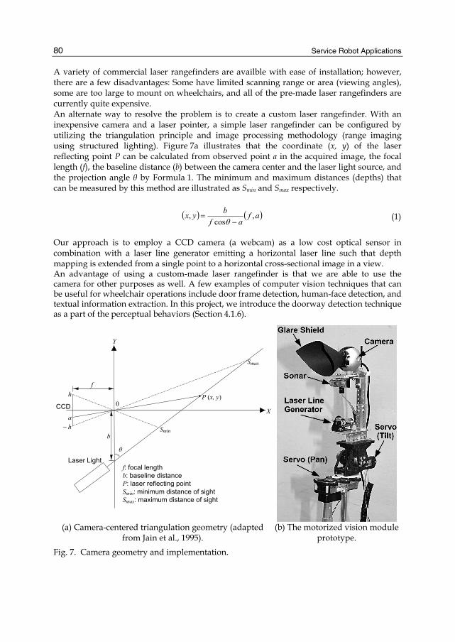
A variety of commercial laser rangefinders are availble with ease of installation; however, there are a few disadvantages: Some have limited scanning range or area (viewing angles), some are too large to mount on wheelchairs, and all of the pre-made laser rangefinders are currently quite expensive. An alternate way to resolve the problem is to create a custom laser rangefinder. With an inexpensive camera and a laser pointer, a simple laser rangefinder can be configured by utilizing the triangulation principle and image processing methodology (range imaging using structured lighting). Figure 7a illustrates that the coordinate (x, y) of the laser reflecting point P can be calculated from observed point a in the acquired image, the focal length (f), the baseline distance (b) between the camera center and the laser light source, and the projection angle θ by Formula 1. The minimum and maximum distances (depths) that can be measured by this method are illustrated as Smin and Smax respectively.
( ) ( )afaf
byx ,cos
,−
=θ
(1)
Our approach is to employ a CCD camera (a webcam) as a low cost optical sensor in combination with a laser line generator emitting a horizontal laser line such that depth mapping is extended from a single point to a horizontal cross-sectional image in a view. An advantage of using a custom-made laser rangefinder is that we are able to use the camera for other purposes as well. A few examples of computer vision techniques that can be useful for wheelchair operations include door frame detection, human-face detection, and textual information extraction. In this project, we introduce the doorway detection technique as a part of the perceptual behaviors (Section 4.1.6).
θ
X
b
Y
f
0
− ha
h
f: focal lengthb: baseline distanceP: laser reflecting pointSmin: minimum distance of sightSmax: maximum distance of sight
Smin
Smax
P (x, y)
Laser Light
CCD
(a) Camera-centered triangulation geometry (adapted
from Jain et al., 1995). (b) The motorized vision module
prototype.
Fig. 7. Camera geometry and implementation.
Perceptual Navigation for Semi-Autonomous Wheelchair Operations
81
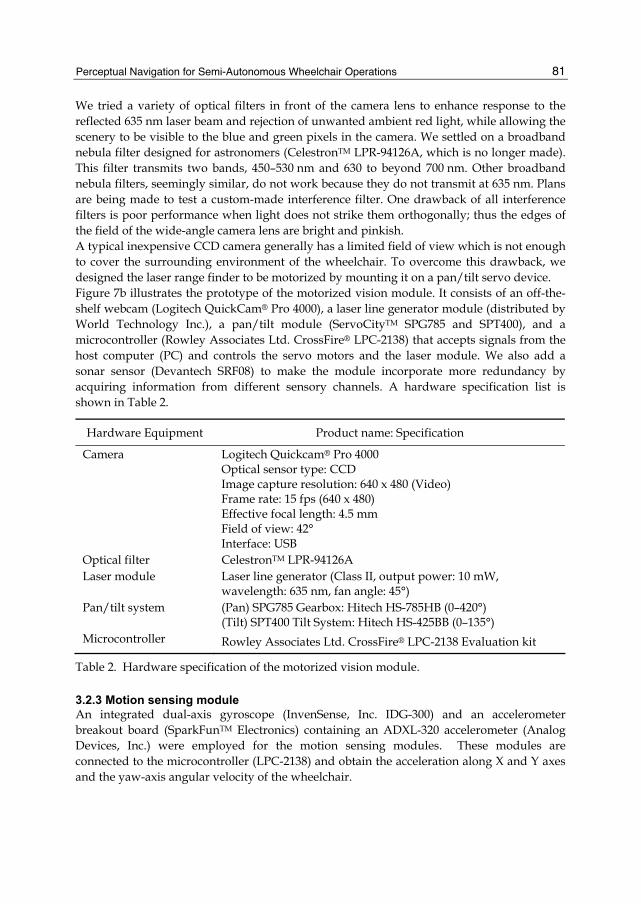
We tried a variety of optical filters in front of the camera lens to enhance response to the reflected 635 nm laser beam and rejection of unwanted ambient red light, while allowing the scenery to be visible to the blue and green pixels in the camera. We settled on a broadband nebula filter designed for astronomers (CelestronTM LPR-94126A, which is no longer made). This filter transmits two bands, 450–530 nm and 630 to beyond 700 nm. Other broadband nebula filters, seemingly similar, do not work because they do not transmit at 635 nm. Plans are being made to test a custom-made interference filter. One drawback of all interference filters is poor performance when light does not strike them orthogonally; thus the edges of the field of the wide-angle camera lens are bright and pinkish. A typical inexpensive CCD camera generally has a limited field of view which is not enough to cover the surrounding environment of the wheelchair. To overcome this drawback, we designed the laser range finder to be motorized by mounting it on a pan/tilt servo device. Figure 7b illustrates the prototype of the motorized vision module. It consists of an off-the-shelf webcam (Logitech QuickCam® Pro 4000), a laser line generator module (distributed by World Technology Inc.), a pan/tilt module (ServoCityTM SPG785 and SPT400), and a microcontroller (Rowley Associates Ltd. CrossFire® LPC-2138) that accepts signals from the host computer (PC) and controls the servo motors and the laser module. We also add a sonar sensor (Devantech SRF08) to make the module incorporate more redundancy by acquiring information from different sensory channels. A hardware specification list is shown in Table 2.
Hardware Equipment Product name: Specification
Camera Logitech Quickcam® Pro 4000 Optical sensor type: CCD Image capture resolution: 640 x 480 (Video) Frame rate: 15 fps (640 x 480) Effective focal length: 4.5 mm Field of view: 42° Interface: USB
Optical filter CelestronTM LPR-94126A Laser module Laser line generator (Class II, output power: 10 mW,
wavelength: 635 nm, fan angle: 45°) Pan/tilt system (Pan) SPG785 Gearbox: Hitech HS-785HB (0–420°)
(Tilt) SPT400 Tilt System: Hitech HS-425BB (0–135°) Microcontroller Rowley Associates Ltd. CrossFire® LPC-2138 Evaluation kit
Table 2. Hardware specification of the motorized vision module.
3.2.3 Motion sensing module An integrated dual-axis gyroscope (InvenSense, Inc. IDG-300) and an accelerometer breakout board (SparkFunTM Electronics) containing an ADXL-320 accelerometer (Analog Devices, Inc.) were employed for the motion sensing modules. These modules are connected to the microcontroller (LPC-2138) and obtain the acceleration along X and Y axes and the yaw-axis angular velocity of the wheelchair.
Service Robot Applications
82
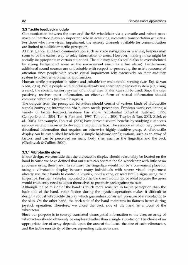
3.3 Tactile feedback module Communication between the user and the SA wheelchair via a versatile and robust man-machine interface plays an important role in achieving successful transportation activities. For those who have visual impairment, the sensory channels available for communication are limited to audible or tactile perception. At first glance, auditory communication such as voice navigation or warning beepers may seem to be the easiest way to relay information to users. However, making noise might be socially inappropriate in certain situations. The auditory signals could also be overwhelmed by strong background noise in the environment (such as a fire alarm). Furthermore, additional sound sources are undesirable with respect to preserving the user’s resource of attention since people with severe visual impairment rely extensively on their auditory system to collect environmental information. Human tactile perception is robust and suitable for multimodal sensing (van Erp & van Veen, 2004). While people with blindness already use their haptic sensory system (e.g. using a cane), the somatic sensory system of another area of skin can still be used. Since the user passively receives most information, an effective form of tactual information should comprise vibrations (vibrotactile signals). The outputs from the perceptual behaviors should consist of various kinds of vibrotactile signals conveying information via human tactile perception. Previous work evaluating a variety of tactile feedback systems has shown substantial potential (Geldard, 1975; Gemperle et al., 2001; Tan & Pentland, 1997; Tan et al., 2000; Traylor & Tan, 2002; Zelek et al., 2003). For example, Tan et al. (2000) have derived several benefits by studying cutaneous sensory saltation in order to develop a haptic interface. The sensory saltation may provide directional information that requires an otherwise highly intuitive grasp. A vibrotactile display can be established by relatively simple hardware configurations, such as an array of tactors, and can be perceived on many body sites, such as the fingertips and the back (Cholewiak & Collins, 2000).
3.3.1 Vibrotactile glove In our design, we conclude that the vibrotactile display should reasonably be located on the hand because we have defined that our users can operate the SA wheelchair with little or no problems using their hand. In contrast, the fingertips would not be a convenient place for using a vibrotactile display because many individuals with severe visual impairment already use their hands to control a joystick, hold a cane, or read Braille signs using their fingertips. Further, a display mounted on the back seat would not be ideal because the users would frequently need to adjust themselves to put their back against the seat. Although the palm side of the hand is much more sensitive in tactile perception than the back side of the hand, volar flexion during the joystick operations makes it difficult to design a robust vibrotactile display which guarantees consistent pressure of a vibrotactor to the skin. On the other hand, the back side of the hand maintains its flatness better during joystick operation. Therefore, we chose the back side of the hand as a locus of the vibrotactor. Since our purpose is to convey translated visuospatial information to the user, an array of vibrotactors should obviously be employed rather than a single vibrotactor. The choice of an appropriate size of array depends upon the area of the locus, the size of each vibrotactor, and the tactile sensitivity of the corresponding cutaneous area.
Perceptual Navigation for Semi-Autonomous Wheelchair Operations
83
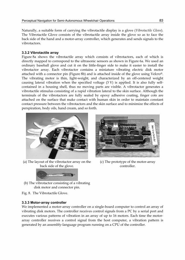
Naturally, a suitable form of carrying the vibrotactile display is a glove (Vibrotactile Glove). The Vibrotactile Glove consists of the vibrotactile array inside the glove so as to face the back side of the hand and a motor-array controller, which generates and sends signals to the vibrotactors.
3.3.2 Vibrotactile array Figure 8a shows the vibrotactile array which consists of vibrotactors, each of which is directly mapped to correspond to the ultrasonic sensors as shown in Figure 6a. We used an ordinary baseball glove and cut it on the little-finger side to make it easier to install the vibrotactor array. Each vibrotactor contains a miniature vibrating electric disk motor attached with a connector pin (Figure 8b) and is attached inside of the glove using Velcro®. The vibrating motor is thin, light-weight, and characterized by an off-centered weight causing lateral vibration when the specified voltage (3 V) is applied. It is also fully self-contained in a housing shell, thus no moving parts are visible. A vibrotactor generates a vibrotactile stimulus consisting of a rapid vibration lateral to the skin surface. Although the terminals of the vibrotactors are fully sealed by epoxy adhesive coating, finger cots are attached on the surface that make contact with human skin in order to maintain constant contact pressure between the vibrotactors and the skin surface and to minimize the effects of perspiration, body oils, hand cream, and so forth.
(a) The layout of the vibrotactor array on the
back side of the glove. (c) The prototype of the motor-array
controller.
(b) The vibrotactor consisting of a vibrating disk motor and connector pin.
Fig. 8. The Vibrotactile Glove.
3.3.3 Motor-array controller We implemented a motor-array controller on a single-board computer to control an array of vibrating disk motors. The controller receives control signals from a PC by a serial port and executes various patterns of vibration in an array of up to 16 motors. Each time the motor-array controller receives a control signal from the host computer, a vibration pattern is generated by an assembly-language program running on a CPU of the controller.
Service Robot Applications
84
The prototype of the motor-array controller is shown in Figure 8c. The CPU is an Atmel AT89C52, a flash-memory derivative of the Intel 8051 (MCS/51) with the same instruction set. Serial input is received through an MC1489A or equivalent RS-232 line receiver. Two of the CPU’s output ports (P0 and P1) are coupled to the motors through SN754410 motor control ICs. The prototype controller is much bulkier than necessary; it was built large to facilitate experimentation. A much smaller version has been designed.
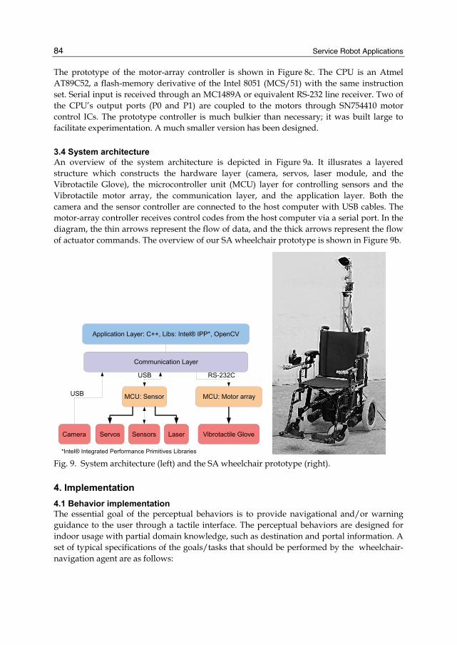
3.4 System architecture An overview of the system architecture is depicted in Figure 9a. It illusrates a layered structure which constructs the hardware layer (camera, servos, laser module, and the Vibrotactile Glove), the microcontroller unit (MCU) layer for controlling sensors and the Vibrotactile motor array, the communication layer, and the application layer. Both the camera and the sensor controller are connected to the host computer with USB cables. The motor-array controller receives control codes from the host computer via a serial port. In the diagram, the thin arrows represent the flow of data, and the thick arrows represent the flow of actuator commands. The overview of our SA wheelchair prototype is shown in Figure 9b.
Fig. 9. System architecture (left) and the SA wheelchair prototype (right).
4. Implementation 4.1 Behavior implementation The essential goal of the perceptual behaviors is to provide navigational and/or warning guidance to the user through a tactile interface. The perceptual behaviors are designed for indoor usage with partial domain knowledge, such as destination and portal information. A set of typical specifications of the goals/tasks that should be performed by the wheelchair-navigation agent are as follows:
Perceptual Navigation for Semi-Autonomous Wheelchair Operations
85
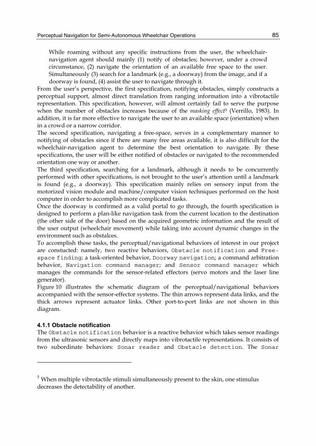
While roaming without any specific instructions from the user, the wheelchair-navigation agent should mainly (1) notify of obstacles; however, under a crowd circumstance, (2) navigate the orientation of an available free space to the user. Simultaneously (3) search for a landmark (e.g., a doorway) from the image, and if a doorway is found, (4) assist the user to navigate through it.
From the user’s perspective, the first specification, notifying obstacles, simply constructs a perceptual support, almost direct translation from ranging information into a vibrotactile representation. This specification, however, will almost certainly fail to serve the purpose when the number of obstacles increases because of the masking effect5 (Verrillo, 1983). In addition, it is far more effective to navigate the user to an available space (orientation) when in a crowd or a narrow corridor. The second specification, navigating a free-space, serves in a complementary manner to notifying of obstacles since if there are many free areas available, it is also difficult for the wheelchair-navigation agent to determine the best orientation to navigate. By these specifications, the user will be either notified of obstacles or navigated to the recommended orientation one way or another. The third specification, searching for a landmark, although it needs to be concurrently performed with other specifications, is not brought to the user’s attention until a landmark is found (e.g., a doorway). This specification mainly relies on sensory input from the motorized vision module and machine/computer vision techniques performed on the host computer in order to accomplish more complicated tasks. Once the doorway is confirmed as a valid portal to go through, the fourth specification is designed to perform a plan-like navigation task from the current location to the destination (the other side of the door) based on the acquired geometric information and the result of the user output (wheelchair movement) while taking into account dynamic changes in the environment such as obstalces. To accomplish these tasks, the perceptual/navigational behaviors of interest in our project are constucted: namely, two reactive behaviors, Obstacle notification and Free-space finding; a task-oriented behavior, Doorway navigation; a command arbitration behavior, Navigation command manager; and Sensor command manager which manages the commands for the sensor-related effectors (servo motors and the laser line generator). Figure 10 illustrates the schematic diagram of the perceptual/navigational behaviors accompanied with the sensor-effector systems. The thin arrows represent data links, and the thick arrows represent actuator links. Other port-to-port links are not shown in this diagram.
4.1.1 Obstacle notification The Obstacle notification behavior is a reactive behavior which takes sensor readings from the ultrasonic sensors and directly maps into vibrotactile representations. It consists of two subordinate behaviors: Sonar reader and Obstacle detection. The Sonar
5 When multiple vibrotactile stimuli simultaneously present to the skin, one stimulus decreases the detectability of another.
Service Robot Applications
86
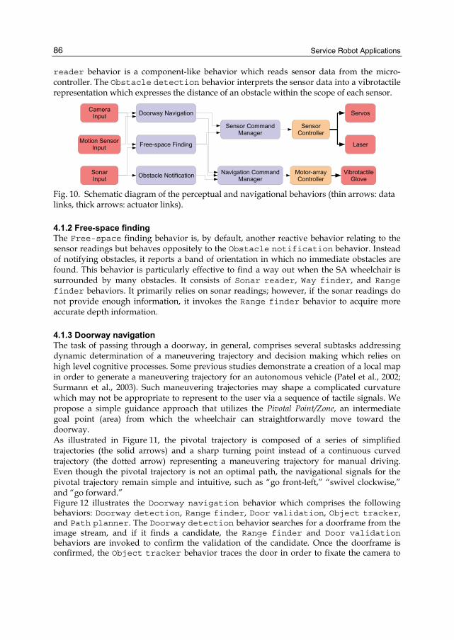
reader behavior is a component-like behavior which reads sensor data from the micro-controller. The Obstacle detection behavior interprets the sensor data into a vibrotactile representation which expresses the distance of an obstacle within the scope of each sensor.
Fig. 10. Schematic diagram of the perceptual and navigational behaviors (thin arrows: data links, thick arrows: actuator links).
4.1.2 Free-space finding The Free-space finding behavior is, by default, another reactive behavior relating to the sensor readings but behaves oppositely to the Obstacle notification behavior. Instead of notifying obstacles, it reports a band of orientation in which no immediate obstacles are found. This behavior is particularly effective to find a way out when the SA wheelchair is surrounded by many obstacles. It consists of Sonar reader, Way finder, and Range finder behaviors. It primarily relies on sonar readings; however, if the sonar readings do not provide enough information, it invokes the Range finder behavior to acquire more accurate depth information.
4.1.3 Doorway navigation The task of passing through a doorway, in general, comprises several subtasks addressing dynamic determination of a maneuvering trajectory and decision making which relies on high level cognitive processes. Some previous studies demonstrate a creation of a local map in order to generate a maneuvering trajectory for an autonomous vehicle (Patel et al., 2002; Surmann et al., 2003). Such maneuvering trajectories may shape a complicated curvature which may not be appropriate to represent to the user via a sequence of tactile signals. We propose a simple guidance approach that utilizes the Pivotal Point/Zone, an intermediate goal point (area) from which the wheelchair can straightforwardly move toward the doorway. As illustrated in Figure 11, the pivotal trajectory is composed of a series of simplified trajectories (the solid arrows) and a sharp turning point instead of a continuous curved trajectory (the dotted arrow) representing a maneuvering trajectory for manual driving. Even though the pivotal trajectory is not an optimal path, the navigational signals for the pivotal trajectory remain simple and intuitive, such as “go front-left,” “swivel clockwise,” and “go forward.” Figure 12 illustrates the Doorway navigation behavior which comprises the following behaviors: Doorway detection, Range finder, Door validation, Object tracker, and Path planner. The Doorway detection behavior searches for a doorframe from the image stream, and if it finds a candidate, the Range finder and Door validation behaviors are invoked to confirm the validation of the candidate. Once the doorframe is confirmed, the Object tracker behavior traces the door in order to fixate the camera to
Perceptual Navigation for Semi-Autonomous Wheelchair Operations
87
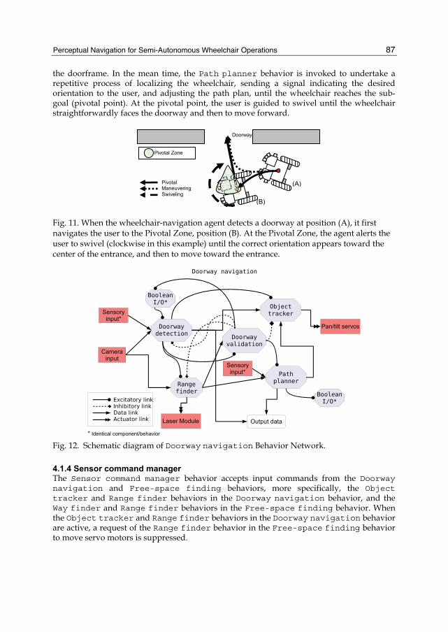
the doorframe. In the mean time, the Path planner behavior is invoked to undertake a repetitive process of localizing the wheelchair, sending a signal indicating the desired orientation to the user, and adjusting the path plan, until the wheelchair reaches the sub-goal (pivotal point). At the pivotal point, the user is guided to swivel until the wheelchair straightforwardly faces the doorway and then to move forward.
Fig. 11. When the wheelchair-navigation agent detects a doorway at position (A), it first navigates the user to the Pivotal Zone, position (B). At the Pivotal Zone, the agent alerts the user to swivel (clockwise in this example) until the correct orientation appears toward the center of the entrance, and then to move toward the entrance.
Fig. 12. Schematic diagram of Doorway navigation Behavior Network.
4.1.4 Sensor command manager The Sensor command manager behavior accepts input commands from the Doorway navigation and Free-space finding behaviors, more specifically, the Object tracker and Range finder behaviors in the Doorway navigation behavior, and the Way finder and Range finder behaviors in the Free-space finding behavior. When the Object tracker and Range finder behaviors in the Doorway navigation behavior are active, a request of the Range finder behavior in the Free-space finding behavior to move servo motors is suppressed.
Pivotal Zone
(A)
(B)
Pivotal Maneuvering Swiveling
Doorway
Service Robot Applications
88
4.1.5 Navigation command manager The Navigation command manager behavior acceptes navigation commands from the Doorway navigation, Free-space finding, and Obstacle notification behaviors, and arbitrates the commmands. By default, commands from the Obstacle notification behavior are sent to the motor-array controller. When more than two immediate obstacles are detected, the commands from the Free-space finding behavior will be sent. If the Doorway navigation behavior issues a command, a command the from Obstacle notification behavior is suppressed and the command from Free-space finding will be fused with the command from the Doorway navigation behavior. The details of the command fusion strategy are not discussed in this chapter.
4.1.6 Doorway detection The Doorway detection behavior constitutes a computer-vision based algorithm to classify doorways. Doorways are classified based on the presence of the door jambs and the lintel. These are represented in the image as two strong vertical lines connected by a horizontal line. First, the image from the camera is converted to greyscale and reduced to half its original size. Edges are extracted by using a custom convolution filter which combines the accurate edge localization of the Laplacian kernel with the directional bias of a Sobel filter to improve detection of vertical lines. The detection of vertical lines is achieved by applying the Probabilistic Hough Transform (Kiryati et al., 1991) to the edge image. The technique searches a proportion α (5 % < α < 15 %) of randomly selected edge pixels in the image to detect line segments. The vertical line segments are passed to an algorithm that merges line segments deemed close enough. The search for the lintel is limited to the region between the top of the image and the top of the lowest vertical line. Within this sub-region, edge extraction is performed by means of a second-order partial derivative. Horizontal line segments are also detected by the Probabilistic Hough Transformation, examined to ensure they are sufficiently horizontal, and then passed to the merging algorithm. After both sets of line segments are collected, a matching algorithm is performed to determine combinations of two vertical lines connected by a horizontal line that construct a doorframe. If the matching criteria for a doorframe are met, the Range finder behavior (Section 4.1.7) is invoked to measure the distance to the door which enables a validation process to increase accuracy and reduce false positives. Once the doorframe is validated, the dimensions of the door candidate are obtained and sent to the linked behaviors.
4.1.7 Range finder The Range finder behavior also constitutes a computer-vision based algorithm to detect a laser line. The laser detection algorithm seeks each laser point per column while eliminating noise and erroneous detection. First, an acquired image is decomposed into its constituent RGB color channels, and an intermediate image is created by subtracting the green channel from the red. The algorithm then seeks a candidate pixel that represents the laser point by means of a second-order differential for each column. The 8 neighboring pixels of each candidate are examined to eliminate single outlier pixels. After outlier points are eliminated, the resulting points are collapsed into a one-dimensional array representing the height in the original image where each point was found. Based on camera calibrations, these points are then mapped into distances and sent to the linked behaviors.
Perceptual Navigation for Semi-Autonomous Wheelchair Operations
89
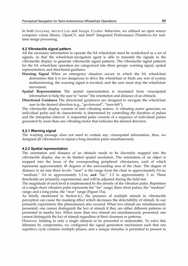
In both Doorway detection and Range Finder behaviors, we utilized an open source computer vision library, OpenCV, and Intel® Integrated Performance Primitives for real-time image processing.
4.2 Vibrotactile signal pattern All the necessary information to operate the SA wheelchair must be symbolized as a set of signals, so that the wheelchair-navigaiton agent is able to transmit the signals to the vibrotactile display to generate vibrotactile signal patterns. The vibrotactile signal patterns for the SA wheelchair operation are categorized into three groups: warning signal, spatial representation, and directional guidance. Warning Signal When an emergency situation occurs in which the SA wheelchair
determines that it is too dangerous to drive the wheelchair or finds any sort of system malfunctioning, the warning signal is invoked, and the user must stop the wheelchair movement.
Spatial Representation The spatial representation is translated from visuospatial information to help the user to “sense” the orientation and distance of an obstacle.
Directional Guidance The directional guidances are designed to navigate the wheelchair user in the desired direction (e.g., “go-forward”, “turn-left”).
The vibrotactile display consists of nine vibrating motors. A vibrating motor generates an individual pulse and its characteristic is determined by controlling the duration of pulses and the interpulse interval. A sequential pulse consists of a sequence of individual pulses generated by more than one vibrating motor that indicates the desired direction.
4.2.1 Warning signal The warning message does not need to contain any visuospatial information, thus, we designed all vibrotactors to repeat a long duration pulse simultaneously.
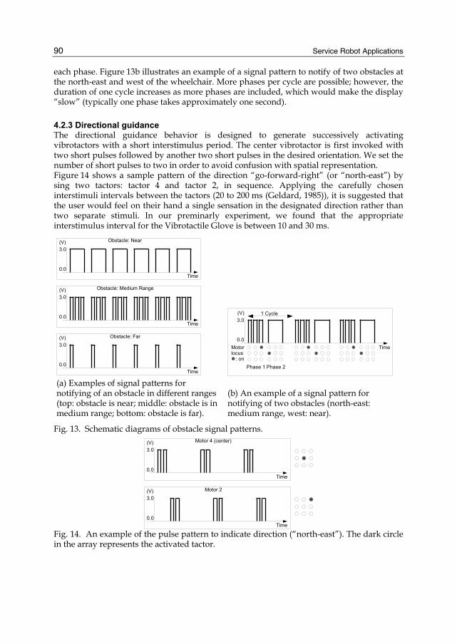
4.2.2 Spatial representation The orientation and distance of an obstacle needs to be discretely mapped into the vibrotactile display due to its limited spatial resolution. The orientation of an object is mapped into the locus of the corresponding peripheral vibrotactors, each of which represents approximately 45 degrees of the surrounding area of the chair. The degree of distance is set into three levels: “near” is the range from the chair to approximately 0.6 m; “medium,” 0.6 to approximately 1.2 m; and “far,” 1.2 to approximately 2 m. These thresholds are primarily experimental, and will be adjusted during the field test. The magnitude of each level is implemented by the density of the vibration pulse. Repetition of a single short vibration pulse represents the “far” range; three short pulses, the “medium” range; and a long pulse, the “near” range (Figure 13a). As briefly mentioned in Section 4.1, the presence of multiple stimuli in vibrotactile perception can cause the masking effect which decreases the detectability of stimuli. In our primarily experiment, this phenomenon also occured. When two stimuli are simultaneously presented, one cannot distinguish the loci of stimuli if they are either different patterns or presented in nearby loci. When more than two stimuli are simultaneously presented, one cannot distinguish the loci of stimuli regardless of their closeness or patterns. However, limiting to only a single obstacle to be presented is undesirable. To solve this dilemma by compromise, we configured the signal generation mechanism such that one repetitive cycle contains multiple phases, and a unique stimulus is permitted to present in
Service Robot Applications
90
each phase. Figure 13b illustrates an example of a signal pattern to notify of two obstacles at the north-east and west of the wheelchair. More phases per cycle are possible; however, the duration of one cycle increases as more phases are included, which would make the display “slow” (typically one phase takes approximately one second).
4.2.3 Directional guidance The directional guidance behavior is designed to generate successively activating vibrotactors with a short interstimulus period. The center vibrotactor is first invoked with two short pulses followed by another two short pulses in the desired orientation. We set the number of short pulses to two in order to avoid confusion with spatial representation. Figure 14 shows a sample pattern of the direction “go-forward-right” (or “north-east”) by sing two tactors: tactor 4 and tactor 2, in sequence. Applying the carefully chosen interstimuli intervals between the tactors (20 to 200 ms (Geldard, 1985)), it is suggested that the user would feel on their hand a single sensation in the designated direction rather than two separate stimuli. In our preminarly experiment, we found that the appropriate interstimulus interval for the Vibrotactile Glove is between 10 and 30 ms.
(a) Examples of signal patterns for notifying of an obstacle in different ranges (top: obstacle is near; middle: obstacle is in medium range; bottom: obstacle is far).
(b) An example of a signal pattern for notifying of two obstacles (north-east: medium range, west: near).
Fig. 13. Schematic diagrams of obstacle signal patterns.
Fig. 14. An example of the pulse pattern to indicate direction (“north-east”). The dark circle in the array represents the activated tactor.
Perceptual Navigation for Semi-Autonomous Wheelchair Operations
91
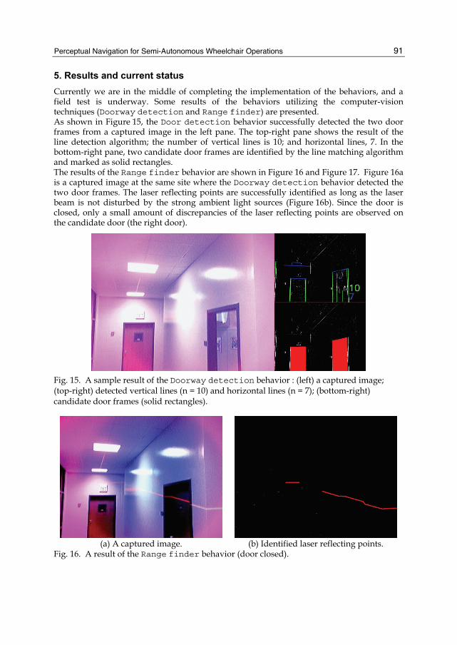
5. Results and current status Currently we are in the middle of completing the implementation of the behaviors, and a field test is underway. Some results of the behaviors utilizing the computer-vision techniques (Doorway detection and Range finder) are presented. As shown in Figure 15, the Door detection behavior successfully detected the two door frames from a captured image in the left pane. The top-right pane shows the result of the line detection algorithm; the number of vertical lines is 10; and horizontal lines, 7. In the bottom-right pane, two candidate door frames are identified by the line matching algorithm and marked as solid rectangles. The results of the Range finder behavior are shown in Figure 16 and Figure 17. Figure 16a is a captured image at the same site where the Doorway detection behavior detected the two door frames. The laser reflecting points are successfully identified as long as the laser beam is not disturbed by the strong ambient light sources (Figure 16b). Since the door is closed, only a small amount of discrepancies of the laser reflecting points are observed on the candidate door (the right door).
Fig. 15. A sample result of the Doorway detection behavior : (left) a captured image; (top-right) detected vertical lines (n = 10) and horizontal lines (n = 7); (bottom-right) candidate door frames (solid rectangles).
(a) A captured image. (b) Identified laser reflecting points.
Fig. 16. A result of the Range finder behavior (door closed).
Service Robot Applications
92
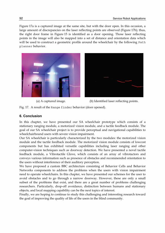
Figure 17a is a captured image at the same site, but with the door open. In this occasion, a large amount of discrepancies on the laser reflecting points are observed (Figure 17b); thus, the right door frame in Figure 15 is identified as a door opening. Those laser reflecting points in the image will also be mapped into a set of distance and orientation data which will be used to construct a geometric profile around the wheelchair by the following Path planner behavior.
(a) A captured image. (b) Identified laser reflecting points.
Fig. 17. A result of the Range finder behavior (door opened).
6. Conclusion In this chapter, we have presented our SA wheelchair prototype which consists of a stationary ranging module, a motorized vision module, and a tactile feedback module. The goal of our SA wheelchair project is to provide perceptual and navigational capabilities to wheelchairbound users with severe vision impairment. Our SA wheelchair is particularly characterized by the two modules: the motorized vision module and the tactile feedback module. The motorized vision module consists of lowcost components but has exhibited versatile capabilities including laser ranging and other computer-vision techniques such as doorway detection. We have presented a novel tactile feedback module, a Vibrotactile Glove, which consists of an array of vibrotactors and conveys various information such as presence of obstacles and recommended orientation to the users without interference of their auditory perception. We have proposed a custom BBC architecture consisting of Behavior Cells and Behavior Networks components to address the problems when the users with vision impairment need to operate wheelchairs. In this chapter, we have presented our schemes for the user to avoid obstacles and to go through a narrow doorway. However, these are only a small subset of the problems that exist, and there are a great number of problems challenging researchers. Particularly, drop-off avoidance, distinction between humans and stationary objects, and local mapping capability can be the next topics of interest. Finally, we are hoping to continue to study this challenging and interesting research toward the goal of improving the quality of life of the users in the blind community.
Perceptual Navigation for Semi-Autonomous Wheelchair Operations
93
7. References Argyros, A. A., Georgiadis, P., Trahanias, P., & Tsakiris, D. P. (2002). Semi-autonomous
navigation of a robotic wheelchair. Journal of Intelligent and Robotic Systems, 34, 315–329.
Arkin, R. C. (1998). Behavior-Based Robots. Cambridge, Massachusetts: The MIT Press. Borgolte, U., Hoyer, H., BÃijhler, C., Heck, H., & Hoelper, R. (1998). Architectural concepts
of a semi-autonomous wheelchair. Journal of Intelligent and Robotic Systems, 22(3), 233–253.
Brooks, R. A. (1991). Integrated Systems Based on Behaviors. SIGART Bulletin, 2(4), 46–50. Cholewiak, R. W., & Collins, A. A. (2000). The generation of vibrotactile patterns on a linear
array: Influences of body site, space, and time. Perception & Psychophysics, 62(6), 1220–1235.
Crisman, J. D., & Cleary, M. E. (1998). Progress on the deictically controlled wheelchair. In V. O. Mittal, H. A. Yanco, J. M. Aronis, & R. C. Simpson (Eds.) Assistive Technology and Artificial Intelligence, Applications in Robotics, User Interfaces and Natural Language Processing, vol. 1458 of Lecture Notes in Computer Science, (pp. 137–149). New York: Springer.
Douglass, J., & Ryan, M. (1987). A pre-school severely disabled boy and his powered wheelchair: A case study. Child Care, Health Development, 13, 303–309.
Geldard, F. A. (1975). Sensory Saltation: Metastability in the Perceptual World. Hillsdale, New Jersey: Lawrence Erlbaum Associates.
Geldard, F. A. (1985). The mutability of time and space on the skin. Journal of the Acoustical Society of America, 77, 233–237.
Gemperle, F., Ota, N., & Siewiorek, D. P. (2001). Design of a wearable tactile display. In Fifth International Symposium on Wearable Computers (ISWC ’01), (pp. 5–12). IEEE Computer Society.
Gomi, T., & Griffith, A. (1998). Developing intelligent wheelchairs for the handicapped. In V. O. Mittal, H. A. Yanco, J. M. Aronis, & R. C. Simpson (Eds.) Assistive Technology and Artificial Intelligence, Applications in Robotics, User Interfaces and Natural Language Processing, vol. 1458 of Lecture Notes in Computer Science, (pp. 150–178). New York: Springer.
Jain, R. C., Kasturi, R., & Schunck, B. G. (1995). Machine Vision. McGraw-Hill. Kiryati, N., Eldar, Y., & Bruckstein, A. (1991). A probabilistic hough transform. Pattern
Recognition, 24, 303–316. Levine, S. P., Bell, D. A., Jaros, L. A., Simpson, R. C., Koren, Y., Member, S., & Borenstein, J.
(1999). The NavChair assistive wheelchair navigation system. IEEE Transactions on Rehabilitation Engineering, 7, 443–451.
Matarić, M. J. (1992). Behavior-based control: Main properties and implications. In IEEE International Conference on Robotics and Automation, Workshop on Architectures for Intelligent Control Systems, (pp. 46–54). Nice, France.
Miller, D. P., & Slack, M. G. (1995). Design and testing of a low-cost robotic wheelchair prototype. Autonomous Robots, 2(1), 77–88.
Nicolescu, M. N., & Matarić, M. J. (2002). A hierarchical architecture for behavior-based robots. In M. Gini, T. Ishida, C. Castelfranchi, & W. L. Johnson (Eds.) Proceedings of the First International Joint Conference on Autonomous Agents and Multiagent Systems (AAMAS’02). ACM Press.
Service Robot Applications
94
Odor, J., & Watson, M. (1994). Learning through smart wheelchairs: A formative evaluation of the effective use of the call centre’s smart wheelchairs as part of children’s emerging mobility, communication, education and personal development. In Final Report to The Nuffield Foundation and the Scottish Office Education Department.
Patel, S., Jung, S.-H., Ostrowski, J. P., Rao, R., & Taylor, C. J. (2002). Sensor based door navigation for a nonholonomic vehicle. In IEEE International Conference on Robotics & Automation, (pp. 3081–3086). Washington, DC.
Paulsson, K., & Christoffersen, M. (1989). Psychosocial aspects of technical aids - how does independent mobility affect the psychosocial and intellectual development of children with physical difficulties? In Proc. 2nd Int. Conf. of the Rehabilitation Engineering Society of North America, Ottawa, (pp. 282–285).
Rönnbäck, S., Piekkari, J., Hyyppä, K., Berglund, T., & Koskinen, S. (2006). A semi-autonomous wheelchair towards user-centered design. In K. Miesenberger, J. Klaus, W. L. Zagler, & A. I. Karshmer (Eds.) ICCHP, vol. 4061 of Lecture Notes in Computer Science, (pp. 701–708). Springer.
Simpson, R., LoPresti, E., Hayashi, S., Guo, S., Ding, D., Ammer,W., Sharma, V., & Cooper, R. (2005). A prototype power assist wheelchair that provides for obstacle detection and avoidance for those with visual impairments. Journal of NeuroEngineering and Rehabilitation, 2(1), 30.
Surmann, H., Nüchter, A., & Hertzberg, J. (2003). An autonomous mobile robot with a 3D laser range finder for 3D exploration and digitalization of indoor environments. Robotics and Autonomous Systems, 45(3-4), 181–198.
Tan, H. Z., Lim, A., & Traylor, R. (2000). A psychophysical study of sensory saltation with an open response paradigm. In Ninth (9th) International Symposium on Haptic Interfaces for Virtual Environment and Teleoperator Systems.
Tan, H. Z., & Pentland, A. (1997). Tactual displays for wearable computing. In The International Symposium on Wearable Computers, (pp. 84–89).
Traylor, R., & Tan, H. Z. (2002). Development of a wearable haptic display for situation awareness in altered-gravity environment: Some initial findings. In Symposium on Haptic Interfaces for Virtual Environment and Teleoperator Systems, (pp. 159–164).
United Nations (2005). World Robotics 2005. Geneva: United Nations. van Erp, J. B., & van Veen, H. A. (2004). Vibrotactile in-vehicle navigation system.
Transportation Research Part F: Traffic Psychology and Behaviour, 7(Issues 4-5), 247–256.
Verburg, G., Balfour, L., Snell, E., & Naumann, S. (1991). Mobility training in the home and school environment for persons with developmental delay. In Final Report to Ontario Mental Health Foundation and Ministry of Community and Social Services’ Research and Program Evaluation Unit.
Verrillo, R. T. (1983). Vibrotactile masking: Effects of one- and two-site stimulation. Perception and Psychophysics, 33(4), 379–387.
Yanco, H. A. (1998). Wheelesley: A robotic wheelchair system: Indoor navigation and user interface. Lecture Notes in Computer Science, 1458, 256.
Zelek, J. S., Bromley, S., Asmar, D., & Thompson, D. (2003). A haptic glove as a tactilevision sensory substitution for wayfinding. Journal of Visual Impairment & Blindness, 97(10), 1–24.