Embed Size (px)
Citation preview
PPoI
BDJKe
OnOpTintTtagahwsfaibha
Ko
1
rsstrrpcfIdhs
ahlt
N
r
J
Downloaded Fr
erformance and Optimization of Flatlate Fins of Different Geometryn a Round Tube: A Comparativenvestigation
. Kunduepartment of Mechanical Engineering,
adavpur University,olkata 700 032, India
-mail: [email protected]
wing to a uniform thickness, the fin material of a flat plate finear to the tip does not participate optimally in transferring heat.n account of this, two new fin geometries of flat plate fins areroposed for improving the heat transfer rate per unit volume.hese projected fin geometries, namely flat plate fin circumscrib-
ng a circular tube by providing quarter circular cut at the cor-ers of the tip (FQCT) and flat plate fin circumscribing a circularube having circular arc to cut at the tip (FCAT) are suggested.he thermal performance of the said geometric fins has been de-
ermined by a semianalytical method. By using a rigorous semi-nalytical technique, optimization have been demonstrated in aeneralized scheme either by maximizing the rate of heat duty forgiven fin volume or by minimizing the fin volume for a given
eat transfer duty. The optimization study has also been madeith the additional length constraints imposed on one or both
ides of the fluid carrying tube. Finally, it can be demonstratedrom the optimization study that two proposed fins, namely FQCTnd FCAT, can dissipate more rate of heat than the FCT with andentical fin volume and thermophysical parameters. It can alsoe highlighted that the optimum FQCT and FCAT can transfereat at a higher rate in comparison with the annular disk fin whenspace constraint exists. �DOI: 10.1115/1.2717255�
eywords: annular disc fins, fin performance, flat plate fins,ptimization, semianalytical method
IntroductionThe rate of heat transfer between a gas and liquid stream is
estricted because of the low heat transfer coefficient in the gaside. Owing to the thermophysical properties of the gases, the gaside resistance amount to 85% or more of the total thermal resis-ance. External fins are often attached to the primary surface toeduce this thermal resistance as a result size of heat exchangereduces. However, the selection of any particular type of fins de-ends on the geometry of the primary surfaces. The radial oroncentric annular disc fins are one of the most common choicesor enhancing the rate of outside heat transfer from a circular tube.t is well known fact that the rate of heat conduction in the finiminishes gradually along the length. This has given rise to aost of research activities for determination of an optimum finhape.
Schmidt �1� was the first researcher to forward a systematicpproach for the optimum design of fins. By a heuristic argument,e proposed that, for an optimum fin, temperature should be ainear function along the fin length. Proceeding from the linearemperature distribution along the fin length, Schmidt found that
Contributed by the Heat Transfer Division of ASME for publication in the JOUR-
AL OF HEAT TRANSFER. Manuscript received February 15, 2006; final manuscript
eceived January 13, 2007. Review conducted by Anthony M. Jacobi.ournal of Heat Transfer Copyright © 20
om: http://heattransfer.asmedigitalcollection.asme.org/ on 03/04/2013 Ter
the profile of optimum straight fins is a concave parabolic shape.Duffin �2� forwarded a rigorous proof on the optimality criteria ofSchmidt hypothesis �1� through the calculus of variation. How-ever, both Schmidt �1� and Duffin �2� made a simplistic assump-tion to consider the negligible profile curvature while calculating afin surface area. This assumption is known as length of arc ide-alization �LAI� in the literature of fins. Guceri and Maday �3�eliminated LAI and used calculus of variation to find out a profileof minimum volume circular fins for a given heat transfer duty.The optimum profile has been numerically determined through aHamiltonian formulation. It is interesting to note that with theimprovement suggested by Guceri and Maday �3�, an optimum finhas neither a linear temperature profile nor possesses a concaveparabolic shape. The resulting fin geometry needs a large surfacearea to dissipate a required amount of heat for a minimum vol-ume. The optimum profile reported in Ref. �3� is reasonably closeto Schmidt’s concave parabolic profile �1� for a large initial finlength, but closer to the end contains some wavy irregularities.The volume of the fin found in Ref. �3� was only slight smallerthan the volume of the Schmidt’s fin with the same height. Animportant numerical finding in Ref. �3� is that with the lifted LAIassumption, the temperature distribution in the optimum fin is alinear in nature. Recently, Kundu and Das �4� have calculated theprofile of different types of optimum thin fins, namely, longitudi-nal, annular, and spine subject to internal heat generation. Theyhave described a technique for the optimization based on thevariational principle. With the consideration of no heat generation,they have also found that the optimum fin profile for all the ex-amined fins is a parabolic in nature.
All the above fin optimization problems �1–4� involve deter-mining the shape �or profile� of a fin so that for a given rate ofheat dissipation the volume of the material used is a minimum.The solution to this group of problem gives the fin shape with acurved surface. Such optimum shapes are relatively difficult tomanufacture and are hence more expensive. Therefore, on theother hand, select was a suitable simple fin shape is a priory aswell as, finding the dimensions that lead to the maximum heattransfer rate for a given fin volume. Equivalently, a given finshape and a desired heat dissipation rate determine the dimensionsso that the volume of the material used is a minimum. Again, it isa familiar that due to decrease in heat conduction with the finlength, a fin with varying cross section, such as circular, parabolic,triangular or trapezoidal, performs better than a rectangular fin asfar as heat transfer rate per unit weight of the material is con-cerned. However, a fin with varying cross section is too complexto manufacture, and fragile at the sharp end. To avoid these diffi-culties, in most of the heat exchanger applications, an annular finof constant thickness is extensively found.
The analysis of annular disk fins is available in a number ofreferences �5–7�. The optimization of such fins has been con-ducted by Brown �8�. He indicated that for an optimum designcondition of annular disk fins, an increase both in length and inthickness results in an increase in heat transfer duty. However, ifthere is a space constraint on one side of a tube or there is anangular variation of a tube temperature, annular disk fins cannotbe used optimally to dissipate the maximum amount of heat for agiven fin volume. If there is a space constraint on one or bothsides of the tube, the fin volume increases with the fin thicknessonly for the annular disk fin. In this situation, it does not guaranteeoptional use of the fin material. Instead, a saving in fin materialcan be achieved if flat plate fins are employed.
El-Saden �9� presented an analysis of two-dimensional heatconduction in an eccentrically hollow, infinite long cylinder withinternal heat generation. He had given a closed form solution forthe estimation of temperature distribution in the fin with the helpof the bipolar coordinate transformation. For dehumidification of
air on the fin surface, Kazeminejad et al. �10� adopted a numericalJULY 2007, Vol. 129 / 91707 by ASME
ms of Use: http://asme.org/terms
tTdDateestb
pseihttddp
mettrmmccmars
ntma
FF
9
Downloaded Fr
echnique to determine the performance of eccentric annular fins.hey have obtained the temperature profile in the fin using a finiteifference scheme. For a variable base temperature, Kundu andas �11� addressed a numerical technique for the performance
nalysis of an eccentric annular fin. Using a bipolar coordinate forhe proper imposition of the boundary conditions, heat conductionquation in the fin has been solved by a finite difference method tovaluate the temperature profile. They have demonstrated that aaving in fin material may be achieved using an optimum eccen-ric annular fin instead of a concentric one if there exits a variablease temperature.
On the other hand, a flat fin on a round tube �Fig. 1� is the mostopular fin pattern in heat exchanger applications owing to itsimplicity, rigidity, and economical impact. The flat fins are gen-rally made of a high conductive material. The profile of such finss conventionally a rectangular shape. For slight thickness andigh thermal conductivity, the temperature distribution in thehickness of the fin is negligibly small but the temperature varia-ion along the fin length and the temperature in the peripheralirection of the tube cannot be neglected. Therefore, two-imensional temperature field exists in every application of flatlate fins.
Sparrow and Lin �12� demonstrated a new technique to deter-ine the thermal performance of plate fins in a fin-and-tube heat
xchanger for both rectangular and equilateral triangular arrays ofubes. Their solution has satisfied the isothermal boundary condi-ion at the tube surface. The adiabatic condition at the outer pe-iphery of a symmetric sector of the fin has been satisfied approxi-ately. The approximate method referred to as “The sectorethod” has been described by Shah �13� for predicting the effi-
iency of plate fins. The efficiency of various polygonal fins cir-umscribing tubes of different regular geometries has been nu-erically determined by Kuan et al. �14�. For the combined tubes
nd fin geometry, they also estimated the efficiency analyticallyeplacing the actual fin by an equivalent annular fin of the sameurface area.
It is a fact that the fin material of constant cross-sectional fins isot used economically near the fin tip. Actually, this unused ma-erial increases with the increase in length and it becomes maxi-
um at the tip. In the case of an individual flat plate fin of rect-
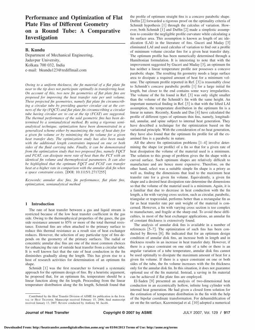
ig. 1 Schematic diagrams of different flat fins: „a… FCT; „b…QCT; and „c… FCAT
ngular or square shape circumscribing a circular tube, the
18 / Vol. 129, JULY 2007
om: http://heattransfer.asmedigitalcollection.asme.org/ on 03/04/2013 Ter
distance of the corner at the tip from the tube center is a maxi-mum. Therefore, for better performance of flat plate fins, fin ma-terial may be removed from the corners near the fin tip �Fig. 1�b��.Another new geometry of flat plate fin with circular arcs to cutnear the tip has been proposed in the present work �Fig. 1�c��.These two modifications of flat plate fins are not only conduciveto material saving but it can also be manufactured easily.
In the present work, the above two new geometric fins �Figs.1�b� and 1�c�� have been proposed. The thermal performance andoptimum design analysis of this type of fins and the conventionalflat-plate fin have been investigated by a semianalytical technique.The temperature distribution in the fin is also determined. The finefficiency and the fin effectiveness are estimated for a wide rangeof thermo-physical parameters. The optimum fin dimensions arecalculated through a comprehensive semi-analytical method fordifferent constraints and thermo-physical properties of a fin. Acomparison has been made among the performance of the pro-posed flat plate fins with the conventional flat plate fin �FCT� andthe annular disk fin �ADF�. From the results, it can be shown thatthe proposed flat fins dissipate heat at a higher rate per unit finvolume than the conventional flat fins irrespective of its any de-sign constraint applied. For the imposition of a length constrainton the optimization problem, a FCT may transfer more rate ofheat than that of an ADF for an identical fin volume.
2 Theoretical DevelopmentThe geometry of a FCT described by thickness 2t, length 2sx,
width 2sy, and outer radius of a tube ri is illustrated schematicallyin Fig. 1�a�. A proposed new geometry of the flat plate fin ofuniform thickness with quarter circular cut at the corners of the tip�FQCT� of radius rc and flat fin of uniform thickness with circulararcs to cut near the tip �FCAT� of radii rcx and rcy are shown inFigs. 1�b� and 1�c�, respectively. For the thermal analysis of all theabove fin geometries, thermal conductivity of the fin material,convective heat transfer coefficient, temperature of the surround-ing fluid, and temperature at the fin base are assumed to be con-stants. It is also assumed that the heat transfer from the fin to thesurrounding are solely due to convection and there is no heatsource in the fin.
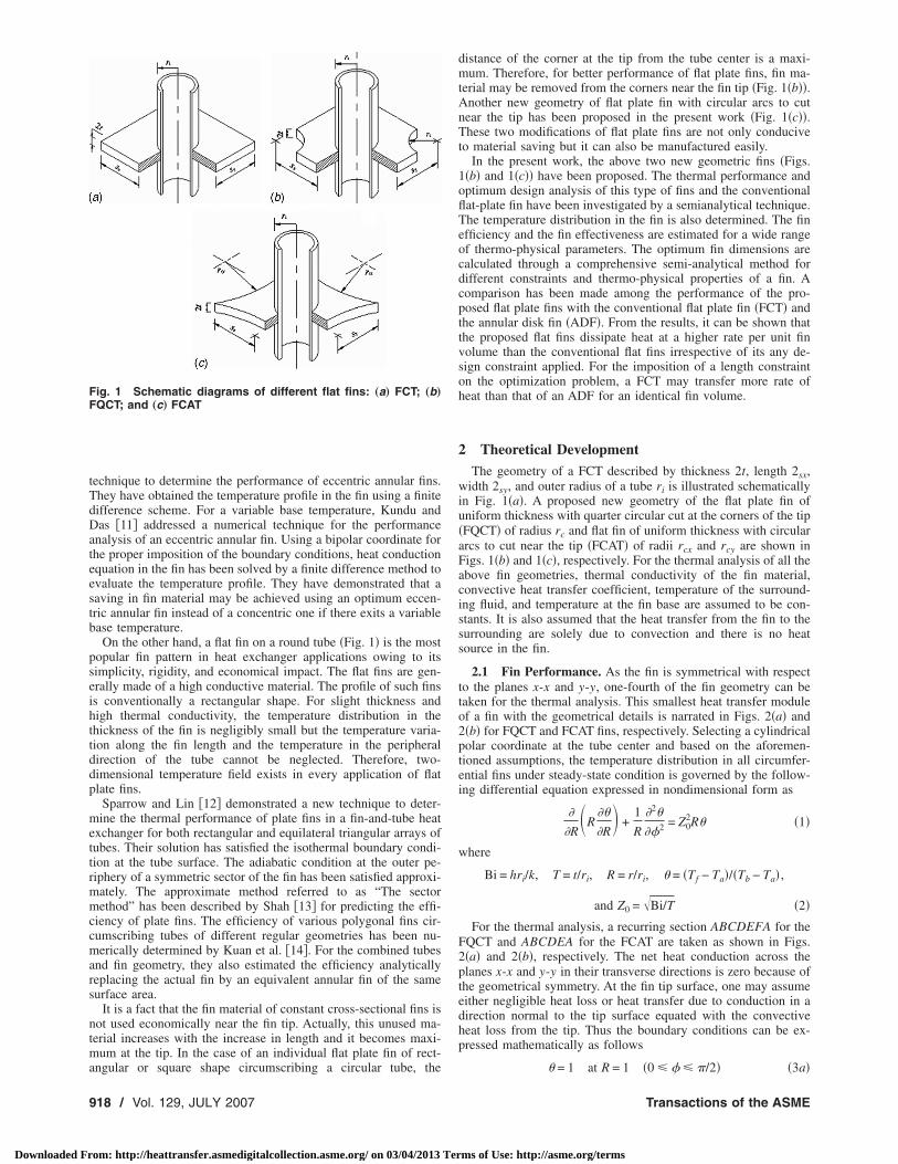
2.1 Fin Performance. As the fin is symmetrical with respectto the planes x-x and y-y, one-fourth of the fin geometry can betaken for the thermal analysis. This smallest heat transfer moduleof a fin with the geometrical details is narrated in Figs. 2�a� and2�b� for FQCT and FCAT fins, respectively. Selecting a cylindricalpolar coordinate at the tube center and based on the aforemen-tioned assumptions, the temperature distribution in all circumfer-ential fins under steady-state condition is governed by the follow-ing differential equation expressed in nondimensional form as
�
�R�R
��
�R� +
1
R
�2�
��2 = Z02R� �1�
where
Bi = hri/k, T = t/ri, R = r/ri, � = �Tf − Ta�/�Tb − Ta� ,
and Z0 = �Bi/T �2�
For the thermal analysis, a recurring section ABCDEFA for theFQCT and ABCDEA for the FCAT are taken as shown in Figs.2�a� and 2�b�, respectively. The net heat conduction across theplanes x-x and y-y in their transverse directions is zero because ofthe geometrical symmetry. At the fin tip surface, one may assumeeither negligible heat loss or heat transfer due to conduction in adirection normal to the tip surface equated with the convectiveheat loss from the tip. Thus the boundary conditions can be ex-pressed mathematically as follows
� = 1 at R = 1 �0 � � � �/2� �3a�
Transactions of the ASME
ms of Use: http://asme.org/terms
w
a
E
FF
J
Downloaded Fr
��/�� = 0 at � = 0 �1 � R � Rt� �3b�
��/�� = 0 at � = �/2 �1 � R � Rt� �3c�
��/�N = − �Z02� at R = Rt �0 � � � �/2� �3d�
here
� = �BitT/Bi convection from the tip
0 no heat loss from the tip �4�
nd N is the direction normal to the tip.
ig. 2 Symmetric heat transfer module: „a… FQCT; and „b…CAT
From the above boundary conditions, it is clear that the first
j=1
ournal of Heat Transfer
om: http://heattransfer.asmedigitalcollection.asme.org/ on 03/04/2013 Ter
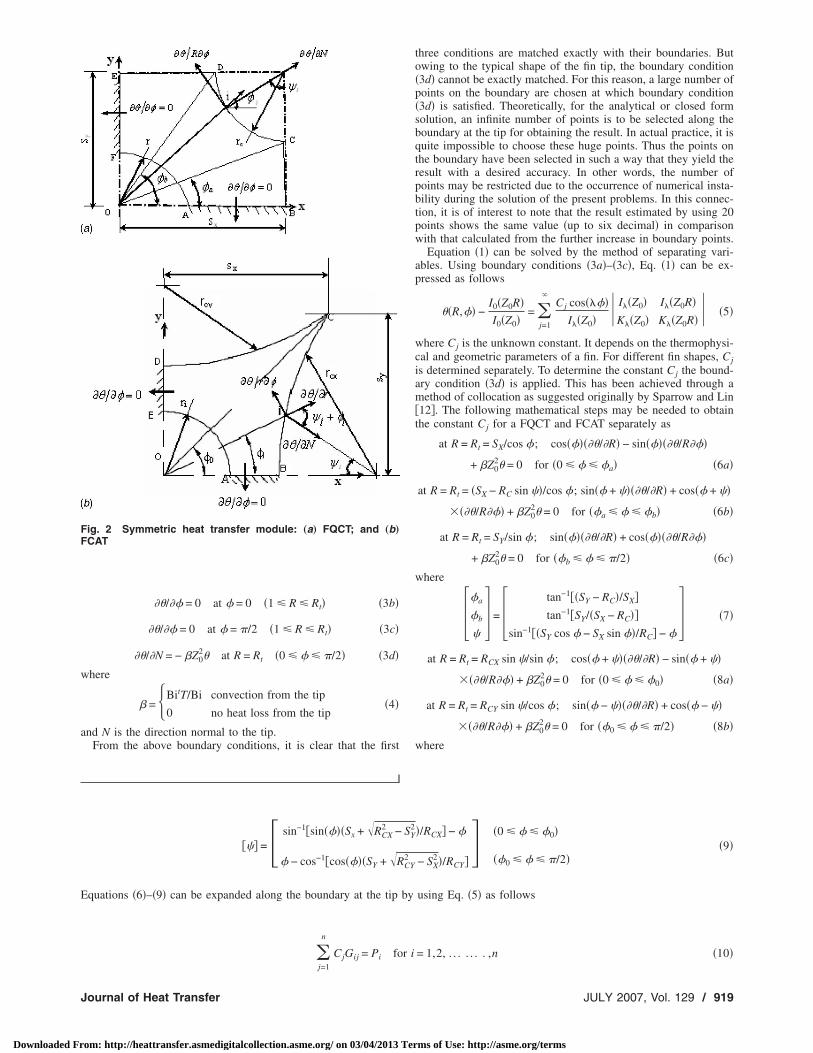
three conditions are matched exactly with their boundaries. Butowing to the typical shape of the fin tip, the boundary condition�3d� cannot be exactly matched. For this reason, a large number ofpoints on the boundary are chosen at which boundary condition�3d� is satisfied. Theoretically, for the analytical or closed formsolution, an infinite number of points is to be selected along theboundary at the tip for obtaining the result. In actual practice, it isquite impossible to choose these huge points. Thus the points onthe boundary have been selected in such a way that they yield theresult with a desired accuracy. In other words, the number ofpoints may be restricted due to the occurrence of numerical insta-bility during the solution of the present problems. In this connec-tion, it is of interest to note that the result estimated by using 20points shows the same value �up to six decimal� in comparisonwith that calculated from the further increase in boundary points.
Equation �1� can be solved by the method of separating vari-ables. Using boundary conditions �3a�–�3c�, Eq. �1� can be ex-pressed as follows
��R,�� −I0�Z0R�I0�Z0�
= j=1
�Cj cos����
I��Z0�� I��Z0� I��Z0R�
K��Z0� K��Z0R�� �5�
where Cj is the unknown constant. It depends on the thermophysi-cal and geometric parameters of a fin. For different fin shapes, Cjis determined separately. To determine the constant Cj the bound-ary condition �3d� is applied. This has been achieved through amethod of collocation as suggested originally by Sparrow and Lin�12�. The following mathematical steps may be needed to obtainthe constant Cj for a FQCT and FCAT separately as
at R = Rt = SX/cos �; cos������/�R� − sin������/R���
+ �Z02� = 0 for �0 � � � �a� �6a�
at R = Rt = �SX − RC sin ��/cos �; sin�� + �����/�R� + cos�� + ��
���/R��� + �Z02� = 0 for ��a � � � �b� �6b�
at R = Rt = SY/sin �; sin������/�R� + cos������/R���
+ �Z02� = 0 for ��b � � � �/2� �6c�
where
��a
�b
� = � tan−1��SY − RC�/SX�
tan−1�SY/�SX − RC��sin−1��SY cos � − SX sin ��/RC� − �
�7�
at R = Rt = RCX sin �/sin �; cos�� + �����/�R� − sin�� + ��
���/R��� + �Z02� = 0 for �0 � � � �0� �8a�
at R = Rt = RCY sin �/cos �; sin�� − �����/�R� + cos�� − ��
���/R��� + �Z02� = 0 for ��0 � � � �/2� �8b�
where
��� =� sin−1�sin����Sx + �RCX2 − SY
2�/RCX� − �
� − cos−1�cos����SY + �RCY2 − SX
2�/RCY�� �0 � � � �0�
��0 � � � �/2��9�
quations �6�–�9� can be expanded along the boundary at the tip by using Eq. �5� as follows
n
CjGij = Pi for i = 1,2, . . . . . . . ,n �10�
JULY 2007, Vol. 129 / 919
ms of Use: http://asme.org/terms
w
a
w
a
Ts
Eettsfi
li
9
Downloaded Fr
here, the expressions of Cj, Gij, and Pi can be written for the FQCT and FCAT, respectively, as
�Gij� =cos���i�RtI��Z0� � Z0RtD1 cos �i + E1D2
Z0RtD1 sin��i + �i� + E2D2
Z0RtD1 sin �i + E3D2 for �0 � �i � �a�
for ��a � �i � �b�for ��b � �i � �/2�
�11�
�D1
D2� = �I��Z0�K�+1�Z0Rt� + I�+1�Z0Rt�K��Z0�
I��Z0Rt�K��Z0�–I��Z0�K��Z0Rt�� �12�
�E1
E2
E3 = � � cos �i + � sin��i�tan���i� + �Z0
2Rt
� sin��i + �i� − � cos��i + �i�tan���i� + �Z02Rt
� sin �i − � cos��i�tan���i� + �Z02Rt
�13�
nd
�Pi� =Z0
I0�Z0��I1�Z0Rt�cos��i� + �Z0I0�Z0Rt�I1�Z0Rt�sin��i + �i� + �Z0I0�Z0Rt�I1�Z0Rt�sin��i� + �Z0I0�Z0Rt�
for �0 � �i � �a�for ��a � �i � �b�for ��b � �i � �/2�
�14�
�Gij� = �D3
D4� for �0 � �i � �0�
for ��0 � �i � �/2��15�
here
D3 =cos���i�RtI��Z0� � 0 − Z0Rt cos��i + �i� E4
I��Z0Rt� I��Z0� − I�+1�Z0Rt�K��Z0Rt� K��Z0� K�+1�Z0Rt�
� �16�
D4 =cos���i�RtI��Z0� � 0 − Z0Rt sin��i − �i� E5
I��Z0Rt� I��Z0� − I�+1�Z0Rt�K��Z0Rt� K��Z0� K�+1�Z0Rt�
� �17�
�E4
E5� = �� cos��i + �i� + � sin��i + �i�tan���i� + �Z0
2Rt
� sin��i − �i� − � cos��i − �i�tan���i� + �Z02Rt
� for �0 � �i � �0�for ��0 � �i � �/2�
�18�
nd
�Pi� =Z0
I0�Z0��cos��i + �i�I1�Z0Rt� + �Z0I0�Z0Rt�sin��i − �i�I1�Z0Rt� + �Z0I0�Z0Rt�
� for �0 � �i � �0�for ��0 � �i � �/2�
�19�
he above Eqs. �11�–�19� are functions of angle �i which can beelected as follows
�i = �i/�2�1 + n�� �20�
quation �10� provides a family of ‘n’ numbers of simultaneousquations. They are solved by the Gauss elimination method �15�o obtain ‘n’ numbers of unknown constants �C1–Cn�. Tempera-ure distribution in the fin can now be determined from Eq. �5� byubstituting these unknown constants C1–Cn, when geometry of an, tip loss parameter �, and fin parameter Z0 are known.The rate of heat transfer through a flat plate fin can be calcu-
ated from the known temperature distribution in the fin by apply-ng Fourier’s law of heat conduction at the base as
�Q� = �q/4�kri�Tb − Ta�� = �−2T
��
0
�/2
���/�R�R=1d��=
Z0T�C W�K �Z �,I �Z �� − I �Z �� �21�
�I0�Z0�� 1 0 0 0 0 1 0
20 / Vol. 129, JULY 2007
om: http://heattransfer.asmedigitalcollection.asme.org/ on 03/04/2013 Ter
where W is the Wronskian determinant given as
W�K0�Z0�,I0�Z0�� = �K0�Z0� I0�Z0�d�K0�Z0��/dZ0 d�I0�Z0��/dZ0
� = 1/Z0
�22�
Combining Eqs. �21� and �22�, it yields the dimensionless heatdissipation rate expressed as
�Q� = T�C1 − Z0I1�Z0��/I0�Z0� �23�
The fin efficiency is defined as the ratio of actual heat transfer rate
to the maximum or ideal heat transfer rate. The ideal heat transfer
rate can be calculated if the entire fin surface is maintained at its
base temperature. The ideal heat transfer rate for the aforemen-
tioned two geometric fins can be expressed in dimensionless form
as
Transactions of the ASME
ms of Use: http://asme.org/terms

w
M
Tht
nittbTRofirfpto
w
F
J
Downloaded Fr
�Qi� = � qi/4�kri�Tb − Ta�Bi�4SXSY − �RC
2 − � + 4��SX + SY − 2RC + �RC/2��/2�
Bi�4SXSY − � − 2�0RCX2 − 2�00RCY
2 + D5 + 4���0RCX + �00RCY��/2� for FQCT
for FCAT�24�
here
�D5
�0
�00 = � 2SY
�RCX2 − SY
2 + 2SX�RCY
2 − SX2
sin−1�sin��0��SX + �RCX2 − SY
2�/RCX� − �0
�0 − cos−1�cos��0��SY + �RCY2 − SX
2�/RCY� �25�
athematically, the fin efficiency can be defined as
�� = �Q/Qi� �26�
he fin effectiveness is defined as the ratio of the rate of actualeat transfer �Q� through a fin to that would be transferred �Qe�
hrough the same base surface area if the fin was not presentf Q and U with respect to T, Sx, Sy, and Rp separately. It yields
ournal of Heat Transfer
om: http://heattransfer.asmedigitalcollection.asme.org/ on 03/04/2013 Ter
�Qe� = �qe/4�kri�Tb − Ta�Bi T
� �27�
Thus the fin effectiveness can be defined as
��� = �Q/Qe� �28�In this connection, it is worth noting that the performance analysisofFCTs may be readily determined from the foregoing analysis ofthe FQCT with the only choice of zero value of RC.
2.2 Optimization. An effort is made to carry out the optimumdesign analysis of the three types of flat fins followed by theprevious analysis. The volume of the different fins can be ex-
pressed in nondimensional forms as follows�U� = � V/2ri3
T�4SXSY − � − �RC2 �
T�4SXSY − 2�0RCX2 − 2�00RC
2 + 2SY�RCX
2 − SY2 + 2SX
�RCY2 − SX
2 − �� for FQCT
for FCAT�29�
In this section, it is noteworthy to mention that for the determi-ation of the optimum dimensions, the tip heat transfer coefficients assumed to be constant and it is equal to the lateral surface heatransfer coefficient. Thus the tip loss parameter � is a sole func-ion of T for the present optimization analysis. For a given Bi,oth the fin volume �U� and heat transfer rate �Q� are functions of, SX, SY, and radius of circular cut Rp �Rp=RC for the FQCT,p=RCX=RCY for the FCAT�. The optimum dimensions can bebtained either by maximizing the rate of heat transfer for a givenn volume or by minimizing the volume for a given heat transferate. The generalized conditions for optimality can be derivedrom the Euler–Lagrange equations �16�. If the Lagrange multi-lier is eliminated from the Euler–Lagrange equations, the condi-ions for the optimality can be expressed as Jacobian determinants
J�Q,U
T,SX� =
��Q,U���T,SX�
= ��Q/�T �Q/�SX
�U/�T �U/�SX� = 0 �30�
J� Q,U
SX,SY� =
��Q,U���SX,SY�
= ��Q/�SX �Q/�SY
�U/�SX �U/�SY� = 0 �31�
and
J� Q,U
SY,Rp� =
��Q,U���SY,Rp�
= ��Q/�SY �Q/�Rp
�U/�SY �U/�Rp� = 0 �32�
Equations �30�–�32� can be simplified by using Eqs. �23� and �29�.It yields the following for the respective FQCT and FCAT as
FQCT� J�Q,U/T,SX�J�Q,U/SX,SY�J�Q,U/SY,Rp�
= �4SY�I0�Z0��C1 + T�C1/�T + Z02I2�Z0�� + 0.5Z0I1�Z0��C1 + Z0I1�Z0��� − �
SX�C1/�SX − SY�C1/�SY
RC��C1/�SY + 2SX�C1/�SY = �0
0
0 �33�
here
� = I0�Z0��4SXSY − � − �RC2 ��C1/�SX = 0 �34�
CAT
� J�Q,U/T,SX�J�Q,U/SX,SY�J�Q,U/SY,Rp�
= �2O1O2 − I0�Z0�O3�C1/�SX
O4�C1/�SX − O2�C1/�SY
O5�C1/�SY − O4�C1/�Rp = �0
0
0 �35�
where
JULY 2007, Vol. 129 / 921
ms of Use: http://asme.org/terms
a
F�S
Atdo�t�r
�onogtrwsRttrfi�oamcgt
9
Downloaded Fr
�O1
O2
O3
O4
= �I0�Z0��C1 + T�C1/�T + Z0
2I2�Z0�� + 0.5Z0I1�Z0��C1 + Z0I1�Z0��
2SY − Rp2��0/�SX − Rp
2��00/�SX + �Rp2 − SX
2 − SX2/�Rp
2 − SX2
4SXSY − 2�0Rp2 − 2�00Rp
2 + 2SY�Rp
2 − SY2 + 2SX
�Rp2 − SX
2 − �
2SX − Rp2��0/�SY − Rp
2��00/�SY + �Rp2 − SX
2 − SY2/�Rp
2 − SY2
�36�
nd
O5 = � − 2�0Rp + SYRp�Rp − SY�−1/2 for 0 � � � �0
− 2�00Rp + SXRp�Rp − SX�−1/2 for �0 � � � �/2
�37�
or the estimation of the above derivatives like �C1 /�T, �C1 /�SX,C1 /�SY, and �C1 /�Rp, Eq. �10� is differentiated with respect to T,X, SY, and Rp separately. It yields
�j=1
n
�Gij�Cj/�T + Cj�Gij/�T�
j=1
n
�Gij�Cj/�SX + Cj�Gij/�SX�
j=1
n
�Gij�Cj/�SY + Cj�Gij/�SY�
j=1
n
�Gij�Cj/�Rp + Cj�Gij/�Rp�
= ��Pi/�T
�Pi/�SX
�Pi/�SY
�Pi/�Rp
for i = 1,2, . . . . . . . ,n �38�
family of n number of equations containing the first-order par-ial derivatives, viz. �Cj /�T, �Cj /�SX, �Cj /�SY, and �Cj /�Rp areescribed in Eq. �38�. To determine these derivatives, the first-rder partial derivative �Gi,j /�T, �Gi,j /�SX, �Gi,j /�SY, andGi,j /�Rp are to be provided to proceed for solving Eq. �38�. Forhis requirement, differentiating Eqs. �11�–�14�, and Eqs.15�–�19� is essential for the analysis of FQCT and FCAT,espectively.
The optimality criteria for flat-plate fins expressed in Eqs.30�–�32� have been made based on the generalized approach ofptimization. For determining the optimum design variables, weeed to solve Eqs. �33� and �35� simultaneously with an equationf the constraint of either heat transfer duty or fin volume. Theeneralized Newton–Raphson technique �15� is adopted to solvehese simultaneous equations. The convergence criteria and theoot finding algorithm of this numerical scheme are found else-here �15�. Here it can be mentioned that to run any iteration, the
econd-order partial derivation of Cj with respect to T, SX, SY, andp separately are provided and the second-order product deriva-
ion of Cj for the said variables are also necessary. The iteration ofhe said numerical method may be repeated until a desired accu-acy �10−8 for the present problem� has been attained. Thus thenal values of the dimensionless parameters like Topt, �SX�opt,SY�opt, and �RP�opt i.e., the optimum dimensionless thickness, theptimum dimensionless length, the optimum dimensionless width,nd the optimum dimensionless radius of circular cut are esti-ated at the end of the iterations by satisfying this convergence
riterion. Next, for the known values of the thermophysical andeometrical parameters, namely, the heat transfer coefficient h, the
hermal conductivity of the fin material k, the outer radius of the22 / Vol. 129, JULY 2007
om: http://heattransfer.asmedigitalcollection.asme.org/ on 03/04/2013 Ter
tube ri, the fin temperature at the root Tb and the ambient tem-perature Ta, one can easily calculate the optimum fin length �sx�,the optimum fin width �sy�, the optimum thickness �t�, optimumradius �rp�, and either the maximum heat transferred duty or theminimum fin volume according to a design constraint adopted.
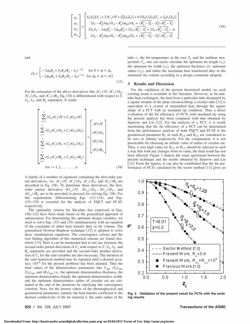
3 Results and DiscussionFor the validation of the present theoretical model, no such
existing result is available in the literature. However, in fin-and-tube heat exchangers, the heat from a particular tube dissipated bya square module of the plate circumscribing a circular tube �12� isequivalent to a system of transmitted heat through the squareshape of a FCT with an insulated tip condition. Thus a directevaluation of the fin efficiency of FCTs with insulated tip usingthe present analysis has been compared with that obtained bySparrow and Lin �12�. For the analysis of a FCT, it is worthmentioning that the fin efficiency of a FCT can be determinedfrom the performance analysis of both FQCT and FCAT if thegeometrical parameter RC or each RCX and RCY are considered tobe zero or infinity respectively. For the computation, it is notpracticable for choosing an infinite value of radius of circular cut.Thus, a very high value for RCX or RCY should be selected in sucha way that with any changes from its value, the final result has notbeen affected. Figure 3 depicts the exact agreement between thepresent technique and the results obtained by Sparrow and Lin�12�. From the figures, it can also be established that the fin per-formance of FCTs calculated by the sector method �13� gives an
Fig. 3 Validation of the present result for FCTs with the exist-
ing resultsTransactions of the ASME
ms of Use: http://asme.org/terms
oih
piFtfoefiws
tonflZ
Fp„
F=
J
Downloaded Fr
verprediction. But the fin efficiency of a FCT with insulated tips strongly dependent on the fin parameter Z0, half length SX, andalf width SY.
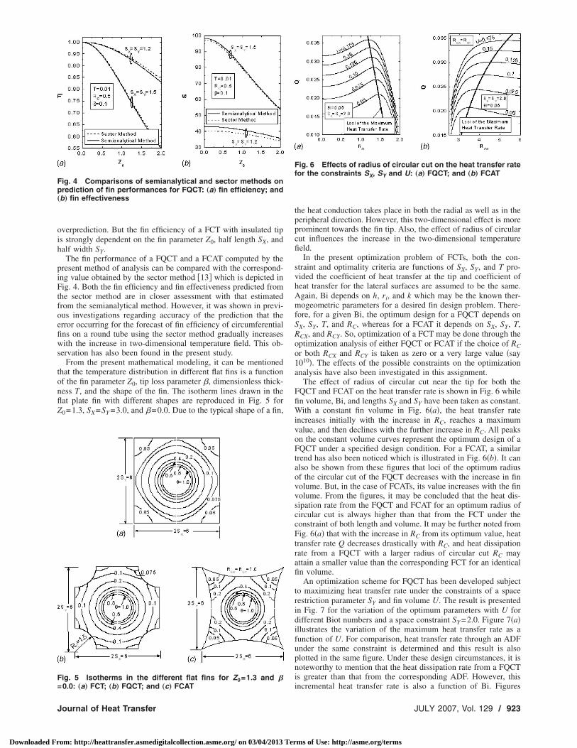
The fin performance of a FQCT and a FCAT computed by theresent method of analysis can be compared with the correspond-ng value obtained by the sector method �13� which is depicted inig. 4. Both the fin efficiency and fin effectiveness predicted from
he sector method are in closer assessment with that estimatedrom the semianalytical method. However, it was shown in previ-us investigations regarding accuracy of the prediction that therror occurring for the forecast of fin efficiency of circumferentialns on a round tube using the sector method gradually increasesith the increase in two-dimensional temperature field. This ob-
ervation has also been found in the present study.From the present mathematical modeling, it can be mentioned
hat the temperature distribution in different flat fins is a functionf the fin parameter Z0, tip loss parameter �, dimensionless thick-ess T, and the shape of the fin. The isotherm lines drawn in theat plate fin with different shapes are reproduced in Fig. 5 for0=1.3, SX=SY =3.0, and �=0.0. Due to the typical shape of a fin,
ig. 4 Comparisons of semianalytical and sector methods onrediction of fin performances for FQCT: „a… fin efficiency; andb… fin effectiveness
ig. 5 Isotherms in the different flat fins for Z0=1.3 and �
0.0: „a… FCT; „b… FQCT; and „c… FCATournal of Heat Transfer
om: http://heattransfer.asmedigitalcollection.asme.org/ on 03/04/2013 Ter
the heat conduction takes place in both the radial as well as in theperipheral direction. However, this two-dimensional effect is moreprominent towards the fin tip. Also, the effect of radius of circularcut influences the increase in the two-dimensional temperaturefield.
In the present optimization problem of FCTs, both the con-straint and optimality criteria are functions of SX, SY, and T pro-vided the coefficient of heat transfer at the tip and coefficient ofheat transfer for the lateral surfaces are assumed to be the same.Again, Bi depends on h, ri, and k which may be the known ther-mogeometric parameters for a desired fin design problem. There-fore, for a given Bi, the optimum design for a FQCT depends onSX, SY, T, and RC, whereas for a FCAT it depends on SX, SY, T,RCX, and RCY. So, optimization of a FCT may be done through theoptimization analysis of either FQCT or FCAT if the choice of RCor both RCX and RCY is taken as zero or a very large value �say1010�. The effects of the possible constraints on the optimizationanalysis have also been investigated in this assignment.
The effect of radius of circular cut near the tip for both theFQCT and FCAT on the heat transfer rate is shown in Fig. 6 whilefin volume, Bi, and lengths SX and SY have been taken as constant.With a constant fin volume in Fig. 6�a�, the heat transfer rateincreases initially with the increase in RC, reaches a maximumvalue, and then declines with the further increase in RC. All peakson the constant volume curves represent the optimum design of aFQCT under a specified design condition. For a FCAT, a similartrend has also been noticed which is illustrated in Fig. 6�b�. It canalso be shown from these figures that loci of the optimum radiusof the circular cut of the FQCT decreases with the increase in finvolume. But, in the case of FCATs, its value increases with the finvolume. From the figures, it may be concluded that the heat dis-sipation rate from the FQCT and FCAT for an optimum radius ofcircular cut is always higher than that from the FCT under theconstraint of both length and volume. It may be further noted fromFig. 6�a� that with the increase in RC from its optimum value, heattransfer rate Q decreases drastically with RC, and heat dissipationrate from a FQCT with a larger radius of circular cut RC mayattain a smaller value than the corresponding FCT for an identicalfin volume.
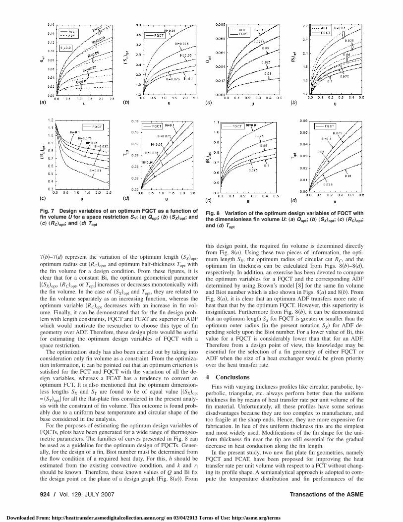
An optimization scheme for FQCT has been developed subjectto maximizing heat transfer rate under the constraints of a spacerestriction parameter SY and fin volume U. The result is presentedin Fig. 7 for the variation of the optimum parameters with U fordifferent Biot numbers and a space constraint SY =2.0. Figure 7�a�illustrates the variation of the maximum heat transfer rate as afunction of U. For comparison, heat transfer rate through an ADFunder the same constraint is determined and this result is alsoplotted in the same figure. Under these design circumstances, it isnoteworthy to mention that the heat dissipation rate from a FQCTis greater than that from the corresponding ADF. However, this
Fig. 6 Effects of radius of circular cut on the heat transfer ratefor the constraints SX, SY and U: „a… FQCT; and „b… FCAT
incremental heat transfer rate is also a function of Bi. Figures
JULY 2007, Vol. 129 / 923
ms of Use: http://asme.org/terms
7otc�ttoulwgfs
ctssol=sab
Fmbatest
Ffi„
9
Downloaded Fr
�b�–7�d� represent the variation of the optimum length �SX�opt,ptimum radius cut �RC�opt, and optimum half-thickness Topt withhe fin volume for a design condition. From these figures, it islear that for a constant Bi, the optimum geometrical parameter�SX�opt, �RC�opt, or Topt� increases or decreases monotonically withhe fin volume. In the case of �SX�opt and Topt, they are related tohe fin volume separately as an increasing function, whereas theptimum variable �RC�opt decreases with an increase in fin vol-me. Finally, it can be demonstrated that for the fin design prob-em with length constraints, FQCT and FCAT are superior to ADFhich would motivate the researcher to choose this type of fineometry over ADF. Therefore, these design plots would be usefulor estimating the optimum design variables of FQCT with apace restriction.
The optimization study has also been carried out by taking intoonsideration only fin volume as a constraint. From the optimiza-ion information, it can be pointed out that an optimum criterion isatisfied for the FCT and FQCT with the variation of all the de-ign variables, whereas a FCAT has a tendency to convert anptimum FCT. It is also mentioned that the optimum dimension-ess lengths SX and SY are found to be of equal value ��SX�opt�SY�opt� for all the flat-plate fins considered in the present analy-
is with the constraint of fin volume. This outcome is found prob-bly due to a uniform base temperature and circular shape of thease considered in the analysis.
For the purposes of estimating the optimum design variables ofQCTs, plots have been generated for a wide range of thermogeo-etric parameters. The families of curves presented in Fig. 8 can
e used as a guideline for the optimum design of FQCTs. Gener-lly, for the design of a fin, Biot number must be determined fromhe flow condition of a required heat duty. For this, h should bestimated from the existing convective condition, and k and rihould be known. Therefore, these known values of Q and Bi fix
ig. 7 Design variables of an optimum FQCT as a function ofn volume U for a space restriction SY: „a… Qopt; „b… „SX…opt; andc… „RC…opt; and „d… Topt
he design point on the plane of a design graph �Fig. 8�a��. From
24 / Vol. 129, JULY 2007
om: http://heattransfer.asmedigitalcollection.asme.org/ on 03/04/2013 Ter
this design point, the required fin volume is determined directlyfrom Fig. 8�a�. Using these two pieces of information, the opti-mum length SX, the optimum radius of circular cut RC, and theoptimum fin thickness can be calculated from Figs. 8�b�–8�d�,respectively. In addition, an exercise has been devoted to comparethe optimum variables for a FQCT and the corresponding ADFdetermined by using Brown’s model �8� for the same fin volumeand Biot number which is also shown in Figs. 8�a� and 8�b�. FromFig. 8�a�, it is clear that an optimum ADF transfers more rate ofheat than that by the optimum FQCT. However, this superiority isinsignificant. Furthermore from Fig. 8�b�, it can be demonstratedthat an optimum length SX for FQCT is greater or smaller than theoptimum outer radius �in the present notation SX� for ADF de-pending solely upon the Biot number. For a lower value of Bi, thisvalue for a FQCT is considerably lower than that for an ADF.Therefore from a design point of view, this knowledge may beessential for the selection of a fin geometry of either FQCT orADF when the size of a heat exchanger would be given priorityover the heat transfer rate.
4 ConclusionsFins with varying thickness profiles like circular, parabolic, hy-
perbolic, triangular, etc. always perform better than the uniformthickness fin by means of heat transfer rate per unit volume of thefin material. Unfortunately, all these profiles have some seriousdisadvantages because they are too complex to manufacture, andtoo fragile at the sharp ends. Hence, they are more expensive forfabrication. In lieu of this uniform thickness fins are the simplestand most widely used. Modifications of the fin shape for the uni-form thickness fin near the tip are still essential for the gradualdecrease in heat conduction along the fin length.
In the present study, two new flat plate fin geometries, namelyFQCT and FCAT, have been proposed for improving the heattransfer rate per unit volume with respect to a FCT without chang-ing its profile shape. A semianalytical approach is adopted to com-
Fig. 8 Variation of the optimum design variables of FQCT withthe dimensionless fin volume U: „a… Qopt; „b… „SX…opt; „c… „RC…opt;and „d… Topt
pute the temperature distribution and fin performances of the
Transactions of the ASME
ms of Use: http://asme.org/terms
Fstmv
goeaorsomgFAficN�vpactas
gsttgt
A
sog
N
J
Downloaded Fr
QCT and FCAT. From the results, it is perceived that these twoimple modified geometries used for the augmentation in heatransfer are shown to improve the fin efficiency for the same ther-
ogeometric parameters. However, for the fin effectiveness, a re-ersed trend has been found.
Optimization of these two modified fins has been done in aeneralized scheme. From the optimization results, it can be dem-nstrated that, for both the volume and length constraints, therexists an optimum radius of circular cut for both the fins. In thebsence of the length constraint, it may not be possible to reach anptimum point for a FCAT. However, for the FQCT, heat transferate is maximized at a particular radius of circular cut under theame design condition. From a comparative study, it may be dem-nstrated that the heat transfer rate through an optimum ADF isarginally greater than that through an optimum FQCT for a
iven fin volume and Bi. However, a smaller envelope shape of aQCT may be obtained in comparison with the correspondingDF at the optimum point. This comparative result may be justi-ed for the lower value of Bi. But under an additional lengthonstraint, FQCT may transfer more rate of heat than an ADF.evertheless, for any circumstances, the proposed flat plate fin
FQCT or FCAT� dissipates more rate of heat compared to a con-entional flat plate fin �FCT� for identical volume and thermo-hysical parameters. Therefore, the proposed flat fins may bedopted by a designer for better utilization of fin material andonsequently they provide a better fin efficiency. For the imposi-ion of length constraints according to the requirement of a design,n alternative ADF using a proposed flat plate fin has been rea-onably established.
Finally, it can be mentioned that any other modification of theeometrical shape of the plate fin is possible, for example, con-idering a straight cut or a reversed circular arc cut at the corner ofhe tip. The analysis of this typical geometry can be done by usinghe present analysis with a slight modification. This optimizedeometry may be able to provide a higher heat dissipation ratehan a conventional plate fin under the same constraints.
cknowledgmentThis research is financially supported by the Jadavpur Univer-
ity �Research Project Grant No. P-1/1057/05 under Seed Supportf Potential for Excellence Scheme� whose assistant is herebyratefully acknowledged.
omenclatureADF annular disk fin
Bi Biot number based on the lateral surface heattransfer coefficient, hri /k
Bit Biot number based on the tip surface heattransfer coefficient, htri /k
Cj unknown constants determined from the tipboundary condition
FCAT flat plate fin of uniform thickness with circulararc to cut at the tip
FCT flat plate fin of uniform thickness circumscrib-ing a circular tube
FQCT flat plate fin of uniform thickness with quartercircular cut at the corner of the tip
Gij variable used in Eq. �11�h convective heat transfer coefficient on the lat-
eral surface �W/m2 K�ht convective heat transfer coefficient on the tip
surface �W/m2 K�i ith point on the tipJ Jacobian determinant defined in Eqs. �30�–�32�
Im�Z� modified Bessel function of first kind of orderm and argument Z
k thermal conductivity of the fin material
�W/m K�ournal of Heat Transfer
om: http://heattransfer.asmedigitalcollection.asme.org/ on 03/04/2013 Ter
Km�Z� modified Bessel function of second kind oforder m and argument Z
n total number of points on the tip at which thetip boundary condition is considered
Pi variable used in Eqs. �14� and �19� for theFQCT and FCAT, respectively
q actual rate of heat dissipation �W�Q dimensionless actual heat dissipation rate
�q /4�kri�Tb−Ta��qe heat dissipation rate from the base surface with
considering no fin condition �W�Qe dimensionless heat dissipation rate
�qe /4�kri�Tb−Ta��qi ideal heat dissipation rate �W�Qi dimensionless ideal heat dissipation rate
�qi /4�kri�Tb−Ta��r radial distance of any point in the fin measured
from the tube center �m�R dimensionless radial distance, r /rirc radius of circular cut at the corner of the tip
�m�RC dimensionless radius of circular cut, rc /rircx radius of circular arc cut at the tip as shown in
Fig. 2 �m�RCX dimensionless radius arc cut at the tip, rcx /rircy radius of circular arc cut at the tip as shown in
Fig. 2 �m�RCY dimensionless radius arc cut at the tip, rcy /ri
ri outer radius of the tube �m�rt radial tip distance from the tube center �m�Rt dimensionless radial tip distance, rt /risx half fin length �m�SX dimensionless fin length, sx /risy half fin width �m�SY dimensionless fin width, sy /ri
t half fin thickness �m�T dimensionless fin thickness, t /ri
Ta temperature of the surrounding fluid �K�Tb fin base temperature �K�Tf local fin temperature �K�U dimensionless fin volume, V /2ri
3
V fin volume �m3�W Wronskian determinant, see Eq. �22�
x ,y Cartesian coordinate shown in Fig. 2 �m�Z0 fin parameter, �Bi/T�1/2
Greek Letters� tip loss parameter, BitT /Bi� fin effectiveness defined in Eq. �28� fin efficiency defined in Eq. �26�� eigenvalue, 2�j−1�� dimensionless temperature �Tf −Ta� / �Tb−Ta�� angular position of any point in the fin �rad�
�0 angle, see Fig. 2�b� �rad��a tan−1��Sy −RC� /Sx�, see Fig. 2�a� �rad��b tan−1�Sy / �Sx−RC��, see Fig. 2�a� �rad��i angular position of ith point on the tip bound-
ary of a fin �rad�� angle defined in Eqs. �7� and �9� for FQCT
and FCAT, respectively �rad��0 ,�00 angle defined in Eq. �25� �rad�
�i angle, see Fig. 2 �rad�� defined in Eq. �35�
Subscriptsi ith point
opt optimum
JULY 2007, Vol. 129 / 925
ms of Use: http://asme.org/terms
R
9
Downloaded Fr
eferences�1� Schmidt, E., 1926, “Die Warmeubertragung durch Rippen,” Z. Ver. Dtsch. Inc.,
70, pp. 885–889.�2� Duffin, R., 1959, “A Variational Problem Relating to Cooling Fins,” J. Math.
Mech., 8, pp. 47–56.�3� Guceri, S., and Maday, C. J., 1975, “A Least Weight Circular Cooling Fins,”
ASME J. Eng. Ind., 97, pp. 1190–1193.�4� Kundu, B., and Das, P. K., 2005, “Optimum Profile of Thin Fins with Volu-
metric Heat Generation—a Unified Approach,” ASME Trans. J. Heat Transfer,127, pp. 945–948.
�5� Kern, Q. D., and Kraus, D. A., 1972, Extended Surface Heat Transfer,McGraw–Hill, New York.
�6� Kraus, A. D., 1988, “Sixty-Five Years of Extended Surface Technology �1922–1987�,” Appl. Mech. Rev., 41, pp. 321–364.
�7� Aziz, A., 1992, “Optimum Dimensions of Extended Surfaces Operating in aConvective Environment,” Appl. Mech. Rev., 45, pp. 155–173.
�8� Razelos, P., and Imre, K., 1980, “The Optimum Dimensions of Circular Finswith Variable Thermal Parameters,” ASME J. Heat Transfer, 102, pp. 420–
425.26 / Vol. 129, JULY 2007
om: http://heattransfer.asmedigitalcollection.asme.org/ on 03/04/2013 Ter
�9� Brown, A., 1965, “Optimum Dimensions of Uniform Annular Fins,” Int. J.Heat Mass Transfer, 8, pp. 655–662.
�10� Kazeminejad, H., Yaghoubi, M. A., and Sepehri, M., 1993, “Effects of Dehu-midification of Air on the Performance of Eccentric Circular Fins,” Int. J. HeatMass Transfer, 207, pp. 141–146.
�11� Kundu, B., and Das, P. K., 1999, “Performance Analysis of Eccentric AnnularFins with a Variable Base Temperature,” Numer. Heat Transfer, Part A, 36, pp.751–766.
�12� Sparrow, E. M., and Lin, S. H., 1964, “Heat Transfer Characteristics of Po-lygonal and Plate Fins,” Int. J. Heat Mass Transfer, 7, pp. 951–953.
�13� Shah, R. K., 1985, “Compact Heat Exchanger,” Handbook Heat Transfer Ap-plications, 2nd ed., W. M. Rohsenow, J. P. Hartnett, and E. N. Ganic, eds.,McGraw–Hill, New York.
�14� Kuan, D. Y., Aris, R., Davis, H. T., 1984, “Estimation of Fin Efficiencies ofRegular Tubes Arrayed in Circumferential Fins,” Int. J. Heat Mass Transfer,27, pp. 148–151.
�15� Scarborough, J. B., 1966, Numerical Mathematical Analysis, Oxford & IBH,New Delhi, India.
�16� Stoecker, W. F., 1989, Design of Thermal System, 3rd ed., McGraw–Hill, New
York.Transactions of the ASME
ms of Use: http://asme.org/terms