Embed Size (px)
Citation preview
Matthias MAEdERSenior Director Flight Operations SupportAirbus Training India Pvt. Ltd.
Performance Based Navigation: RNP and RNP AR Approaches
1. IntroductionPerformance based Navigation (PbN) is becoming more estab-lished in worldwide operations. It includes approaches called RNP APCH and RNP AR APCH, where RNP stands for Required Navigation Performance, APCH is simply an ab-breviation for Approach and AR for Authorization Required.
RNP and RNP AR procedures al-low crews to fly approaches using internal and very accurate navigation tools, instead of traditionally using external guidance aids. They also allow the replacement of visual and circling approaches by instrument approaches, thereby enhancing the safety of airline operations. They are non-precision approaches although they provide the crews with cues and
procedures similar to those used on precision approaches.
This article first describes how the performance of non-precision ap-proaches has evolved over time; from the step down procedures to the Constant Descent Final Approach (CDFA) concept and finally how this evolution has led to RNP solutions and associated benefits.
All Airbus Fly-by-Wire (FbW) air-craft equipped with GPS are currently certified for RNP approaches, which will constitute the majority of cases. RNP AR capability will usually be necessary in marginal cases, where extra flexibility in approach design is needed. This will be illustrated by the following article in this magazine, dedicated to RNP AR operation.
2. Evolution ofNon-PrecisionApproachesAdvances in technology have modified the way non-precision ap-proaches can be flown:
q The first technological step in-volved the move from the traditional step down approaches (also known as “dive-and-drive” approaches) to the CDFA concept, and the use of FMS systems to compute, then guide on the lateral and vertical ap-proach paths.
q The second step implied the change over to RNAV/RNP ap-proaches, primarily thanks to the in-troduction of GPS to civil aviation.
Safety first #16 July 2013 - 1/5
FAF D5.0 VDP MAP
MDA(H)or DA(H)
1670’
2500’
MV
- Descent from VDPor
- Go-Around
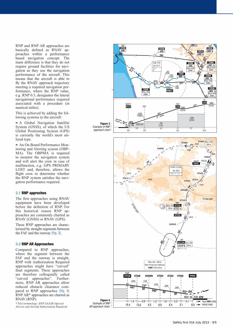
Decision before MDA (H) / VDP or DA(H)/VDP:
FAF VDP MAP
MDA(H)MV
- Descent from VDPor
- Go-Around
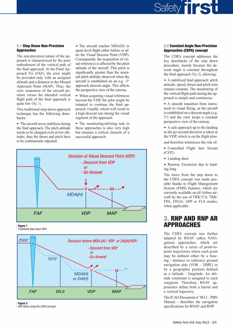
Decision at Visual Descent Point (VDP):
Safety
q The aircraft reaches MDA(H) in quasi-level flight either before or af-ter the Visual Descent Point (VDP). Consequently, the acquisition of vis-ual references is affected by the pitch attitude of the aircraft. This pitch is significantly greater than the nomi-nal pitch attitude observed when the aircraft is established on an e.g. -3° approach descent angle. This affects the perspective view of the runway.
q When acquiring visual references beyond the VDP, the pilot might be tempted to continue the final ap-proach visually, which will result in a high descent rate during the visual segment of the approach.
q The monitoring/advising task in these approaches is also very high but remains a critical element of a successful approach.
2.2 Constant Angle Non-Precision Approaches (CdFA) concept
The CDFA concept addresses the key drawbacks of the step down procedure, mainly because the de-scent angle is constant throughout the final approach (fig. 2), allowing:
q A stabilized final approach: pitch attitude, speed, thrust and pitch trim remain constant. The monitoring of the vertical flight path during the ap-proach is simple and continuous.
q A smooth transition from instru-ment to visual flying, as the aircraft is established on a descent angle (e.g. 3°) and the crew keeps a constant perspective view of the runway.
q A safe approach up to the landing as the go-around decision is taken at the VDP, which is on the flight plan.
and therefore minimizes the risk of:
q Controlled Flight Into Terrain (CFIT)
q Landing short
q Runway Excursion due to land-ing long
The move from the step down to the CDFA concept was made pos-sible thanks to Flight Management System (FMS) features, which are currently available on all Airbus air-craft by the use of TRK/V/S, TRK/FPA, FINAL APP or FLS modes, when applicable.
3. RNP ANd RNP ARAPPROACHESThe CDFA concept was further adapted by RNAV (aRea NAVi-gation) approaches, which are described by a series of point-to-point trajectories where each point may be defined either by a bear-ing / distance to reference ground navigation aids (VOR – DME) or by a geographic position defined as a latitude / longitude. An alti-tude constraint is assigned to each waypoint. Therefore, RNAV ap-proaches define both a lateral and a vertical trajectory.
The ICAO Document n° 9613 – PbN Manual - describes the navigation specifications for RNAV and RNP.
Figure 2NPA flown using the CDFA concept
Figure 1Traditional step down NPA
2.1 Step down Non-Precision ApproachesThe non-precision nature of the ap-proach is characterized by the poor embodiment of the vertical path of the final approach. At the Final Ap-proach Fix (FAF), the crew might be provided only with an assigned altitude and a distance to the Missed Approach Point (MAP). Thus, the crew awareness of the aircraft po-sition versus the intended vertical flight path of the final approach is quite low (fig. 1).
This traditional step-down approach technique has the following draw-backs:
q The aircraft never stabilizes during the final approach. The pitch attitude needs to be changed even at low alti-tudes, thus the thrust and pitch have to be continuously adjusted.
Safety first #16 July 2013 - 2/5
ALT/(HGT): ftDistances : NM
NOT FOR OPERATIONAL USE
CAT. : A B C DAD ELEV : 4395, THR ELEV : 4318 (148 hPa)
Kathmandu - VNKTRNAV (RNP) - APPROACH - RWY02
V2.0 04 APR 2012 CHG : AD coord MAPt FO
VAR : 0°W (10) APP 1
Pro
ced
ure
des
ign
an
d c
har
tin
g :
by
ENA
C/C
GX
AER
O fo
r QU
OVA
DIS
- ©
201
2
QUOVADIS® GéoTITAN® & AIP-GIS Charting®
AUTHORIZATION REQUIREDARP: 27°41'50"N 085°21'29"E
APP : 120.6TWR : 118.1GND : 121.9
4500'
6500'
8500'
RNP 1.0 -> 0.3
RNP 0.3 -> 1.0
Minimum Temperature: -10°C
DA
Next WPt (NM) RW02 (NM)
Trans Alt : 13500’
KT532
2.516.9
IF
RF
2.8°
6500
8700
RDH : 50 THR: 4318(2182)
0.0
(4382)
3.114.4 9.2 8.0 6.41.4
KT520��KT524DOVANKT528
52806740
71008240
RW02KT530FAP
KT522
6260
13.03.8 1.2 1.6 3.3 3.1
RFRF
RF
022°
345°040°
Missed Approach RNP 0.3 until KT613Climb to 10500' via the RNAV (RNP) missed approach to MANRI.At MANRI hold or start a new approach viaMANRI1R transition.
DCBA
TA C
VIS (m)ALSDA (H)
4600 (290)
RNP 0.3
4630 (320)4650 (340)
4670 (360)
VIS (m) no ALS
650
700800
900
1400
14001500
1600
25 NM ARP
10 NM ARP
1 min 30
126°
306°10500
1 m
in 3
0
1050
0
022°
202°
Max IAS : 230 ktMax Protection Altitude:
19000' (1013 hPa)
Max IAS : 230 ktMax Protection Altitude:
15000' (1013 hPa)
KTM 113.20 Ch 79 X
Holding entry protected along the RNP AR trajectory
075° KTM
320°BHP
306°
022°
272°
230°
022°
022°
345°
040°
022°
7.0
1.9
1.4
2.5
3.1
3.8
1.2
1.6
3.3
1.6
5.4
5.95.9
12.0
8.0
6.6
18.2
3.0
RATANIAF
10500Max IAS
230 kt
GURAS
KT528
KT530FAP
Max IAS170 kt
DOVAN
KT522
KT606
RW02MAPT
DARKE
KT613
PIPRA
THR20
KT520
KT619
KT532IF
KT524
KT604 Max IAS180 kt
KT614
MANRI10500
Max IAS250 kt
2.8° 8700
085° 00' 085° 20'084° 40'
27°
40'
27°
20'
MSA 25 NM KTM21100135°
255°
050° 11600
10500
RF requiredDual GNSS required
4610
8287
5154
4535
4938
5538
5466
6772
8530
6801
5322
6312
ALT/(HGT): ftDistances : NM
NOT FOR OPERATIONAL USE
CAT. : A B C DAD ELEV : 4395, THR ELEV : 4318 (148 hPa)
Kathmandu - VNKTRNAV (RNP) - APPROACH - RWY02
V2.0 04 APR 2012 CHG : AD coord MAPt FO
VAR : 0°W (10) APP 1
Pro
ced
ure
des
ign
an
d c
har
tin
g :
by
ENA
C/C
GX
AER
O fo
r QU
OVA
DIS
- ©
201
2
QUOVADIS® GéoTITAN® & AIP-GIS Charting®
AUTHORIZATION REQUIREDARP: 27°41'50"N 085°21'29"E
APP : 120.6TWR : 118.1GND : 121.9
4500'
6500'
8500'
RNP 1.0 -> 0.3
RNP 0.3 -> 1.0
Minimum Temperature: -10°C
DA
Next WPt (NM) RW02 (NM)
Trans Alt : 13500’
KT532
2.516.9
IF
RF
2.8°
6500
8700
RDH : 50 THR: 4318(2182)
0.0
(4382)
3.114.4 9.2 8.0 6.41.4
KT520��KT524DOVANKT528
52806740
71008240
RW02KT530FAP
KT522
6260
13.03.8 1.2 1.6 3.3 3.1
RF RF
RF
022°
345°040°
Missed Approach RNP 0.3 until KT613Climb to 10500' via the RNAV (RNP) missed approach to MANRI.At MANRI hold or start a new approach viaMANRI1R transition.
DCBA
TA C
VIS (m)ALSDA (H)
4600 (290)
RNP 0.3
4630 (320)4650 (340)
4670 (360)
VIS (m) no ALS
650
700800
900
1400
14001500
1600
25 NMARP
10 NM ARP
1 min 30
126°
306°10500
1 m
in 3
0
1050
0
022°
202°
Max IAS : 230 ktMax Protection Altitude:
19000' (1013 hPa)
Max IAS : 230 ktMax Protection Altitude:
15000' (1013 hPa)
KTM 113.20 Ch 79 X
Holding entry protected along the RNP AR trajectory
075° KTM320°BHP
306°
022°
272°
230°
022°
022°
345°
040°
022°
7.0
1.9
1.4
2.5
3.1
3.8
1.2
1.6
3.3
1.6
5.4
5.95.9
12.0
8.0
6.6
18.2
3.0
RATANIAF
10500Max IAS
230 kt
GURAS
KT528
KT530FAP
Max IAS170 kt
DOVAN
KT522
KT606
RW02MAPT
DARKE
KT613
PIPRA
THR20
KT520
KT619
KT532IF
KT524
KT604 Max IAS180 kt
KT614
MANRI10500
Max IAS250 kt
2.8° 8700
085° 00' 085° 20'084° 40'
27°
40'
27°
20'
MSA 25 NM KTM21100135°
255°
050° 11600
10500
RF requiredDual GNSS required
4610
8287
5154
4535
4938
5538
5466
6772
8530
6801
5322
6312
30 NM CIA
095° 100°
143°
143°
143°
158°
201°
207°
207°
337°
271°271°271°
17.818.6
6.6
7.3
5.6
5.0
5.0
3.23.3
10.0
6.65.29.2
312°20.5
1 min
337°
157°
5800
1 min
095°
275°
8700
1 min
153°
333°
4700
10 NM ARP
MAPT RW27
4700CI540
IAF
8700CI520
IAF
Max IAS220kt
5800CI530IAF
Max IAS220kt
3800CI504
IF
Max IAS240kt
CI550
Max IAS220kt
4700CI508
3000CI502FAFFAF
Max IAS220kt
4700CI506
5500
CI5129000
5500CI510
6500
IAFCI516
5200CI5144700
CI538
207(177)
187(157)
210(180)
CIA 113Ch 77 Y
CTR (D) COCHINFL 145SFC
SFCSFC20002000VO R-191AVO R-191A
40000SFC
VO D-172A40000SFC
VO D-172A
076° 00'
10°00'
10°10'
076° 40'076° 20'
10°30'
11NM180°
360°
270°090°
MSA 25 NM VOR CIA
3600
2500 5600
6500
4100
MSA 25 NM CI540
240°
290°
3000 5300
Trans. Alt. : 11000 ft
CAT. A B C DINSTRUMENT APPROACH
AD ELEV : 30, THR ELEV : 30 (1 hPa) RNAV(GNSS)-APPROACH-RWY27
COCHIN INTL - VOCI
AD MINIMA : Altitude and height in feet - VIS in meters. REF HGT : THR ELEV
RW27 2 3 4 5 6 7 8 9
ALT 720 1030 1350 1670 1990 2310 2630 2950(HGT) (690) (1000) (1320) (1640) (1960) (2280) (2600) (2920)
CHG: WP name08 SEP 2011
TWR: Cochin Tower 118.8 - 121.5
ATIS: Cochin Information 126.2 APP: Cochin Approach 119.75 - 121.5
DCBA
TA C
RVRDA (DH)
OCA (OCH): 433 (403) OCA (OCH): 457 (427)
440 (410) 460 (430)
510 (480) 1900
2800
3700
4600
570 (540)
740 (710)
740 (710)
MDA (MDH) VISRVR MDA (MDH)
LNAV/VNAV LNAV (with SDF)CIRCLING (1)
V1R2
(1) Visual manoeuvring (circling) prohibited to the south of the runway.
For uncompensated BARO-VNAV system : Minimum Temperature +5°C
2000 FT
4000 FTFor regulation, Max IAS 220kt during the approach except other ATC clearance.
VAR 3°W (10)
0.0 3.0 9.2 14.46.2 5.23.0
740(710)
2300(2270)
MDA (H)MDA
DA
Missed Approach:
Climb up to CI550 (Mag track 271°),then turn right to CI540climbing up to 4700ft.Do not exceed 240kt.
MAPTRW27 SDF
FAFCI502
IF CI504
(NM)Next WPtTHR (NM)
RDH: 50RDH: 50
271°271°
271°
271°
3° - 5.2%
3000(2970)
3800(3770)
1030(1000)
GNSS HoldingMax IAS : 220 kt
Max Protection Altitude: 11000' (1013hPa)
GNSS HoldingMax IAS : 240 kt
Max Protection Altitude: 14000' (1013 hPa)
GNSS HoldingMax IAS : 220 ktMax Protection
Altitude: 12000' (1013 hPa)
NOT FOR OPERATIONAL USEThis procedure needs flight check before operational approval.
Proc
edur
e d
esig
n a
nd
ch
arti
ng
:b
y EN
AC
/CG
x-A
ERO
in S
YS-P
roc
for Q
UO
VAD
IS/A
IRBU
S - ©
201
0G
éoTI
TAN
® &
AIP
-GIS
Ch
arti
ng
®
DIST NM
30 NM CIA
095° 100°
143°
143°
143°
158°
201°
207°
207°
337°
271°271°271°
17.818.6
6.6
7.3
5.6
5.0
5.0
3.2
3.3
10.0
6.65.29.2
312°20.5
1 min
337°
157°
5800
1 min
095°
275°
8700
1 min
153°
333°
4700
10 NM ARP
MAPT RW27
4700CI540
IAF
8700CI520
IAF
Max IAS220kt
5800CI530IAF
Max IAS220kt
3800CI504
IF
Max IAS240kt
CI550
Max IAS220kt
4700CI508
3000CI502FAFFAF
Max IAS220kt
4700CI506
5500
CI5129000
5500CI510
6500
IAFCI516
5200CI5144700
CI538
207(177)
187(157)
210(180)
CIA 113Ch 77 Y
CTR (D) COCHINFL 145SFC
SFCSFC20002000VO R-191AVO R-191A
40000SFC
VO D-172A40000SFC
VO D-172A
076° 00'
10°00'
10°10'
076° 40'076° 20'
10°30'
11NM180°
360°
270°090°
MSA 25 NM VOR CIA
3600
2500 5600
6500
4100
MSA 25 NM CI540
240°
290°
3000 5300
Trans. Alt. : 11000 ft
CAT. A B C DINSTRUMENT APPROACH
AD ELEV : 30, THR ELEV : 30 (1 hPa) RNAV(GNSS)-APPROACH-RWY27
COCHIN INTL - VOCI
AD MINIMA : Altitude and height in feet - VIS in meters. REF HGT : THR ELEV
RW27 2 3 4 5 6 7 8 9
ALT 720 1030 1350 1670 1990 2310 2630 2950(HGT) (690) (1000) (1320) (1640) (1960) (2280) (2600) (2920)
CHG: WP name08 SEP 2011
TWR: Cochin Tower 118.8 - 121.5
ATIS: Cochin Information 126.2 APP: Cochin Approach 119.75 - 121.5
DCBA
TA C
RVRDA (DH)
OCA (OCH): 433 (403) OCA (OCH): 457 (427)
440 (410) 460 (430)
510 (480) 1900
2800
3700
4600
570 (540)
740 (710)
740 (710)
MDA (MDH) VISRVR MDA (MDH)
LNAV/VNAV LNAV (with SDF)CIRCLING (1)
V1R2
(1) Visual manoeuvring (circling) prohibited to the south of the runway.
For uncompensated BARO-VNAV system : Minimum Temperature +5°C
2000 FT
4000 FTFor regulation, Max IAS 220kt during the approach except other ATC clearance.
VAR 3°W (10)
0.0 3.0 9.2 14.46.2 5.23.0
740(710)
2300(2270)
MDA (H)MDA
DA
Missed Approach:
Climb up to CI550 (Mag track 271°),then turn right to CI540climbing up to 4700ft.Do not exceed 240kt.
MAPTRW27 SDF
FAFCI502
IF CI504
(NM)Next WPtTHR (NM)
RDH: 50RDH: 50
271°271°
271°
271°
3° - 5.2%
3000(2970)
3800(3770)
1030(1000)
GNSS HoldingMax IAS : 220 kt
Max Protection Altitude: 11000' (1013hPa)
GNSS HoldingMax IAS : 240 kt
Max Protection Altitude: 14000' (1013 hPa)
GNSS HoldingMax IAS : 220 ktMax Protection
Altitude: 12000' (1013 hPa)
NOT FOR OPERATIONAL USEThis procedure needs flight check before operational approval.
Pro
ced
ure
des
ign
an
d c
har
tin
g :
by
ENA
C/C
Gx-
AER
O in
SYS
-Pro
c fo
r QU
OVA
DIS
/AIR
BU
S - ©
201
0G
éoTI
TAN
® &
AIP
-GIS
Ch
arti
ng
®
DIST NM
RNP and RNP AR approaches are basically defined as RNAV ap-proaches within a performance based navigation concept. The main difference is that they do not require ground facilities for navi-gation as they use the navigation performance of the aircraft. This means that the aircraft is able to fly the RNAV approach trajectory meeting a required navigation per-formance, where the RNP value, e.g. RNP 0.3, designates the lateralnavigational performance requiredassociated with a procedure (innautical miles).
This is achieved by adding the fol-lowing systems to the aircraft:
q A Global Navigation Satellite System (GNSS), of which the US Global Positioning System (GPS) is currently the world's most uti-lized type.
q An On board Performance Mon-itoring and Alerting system (ObP-MA). The ObPMA is required to monitor the navigation system and will alert the crew in case of malfunction, e.g. GPS PRIMARY LOST and, therefore, allows the flight crew to determine whether the RNP system satisfies the navi-gation performance required.
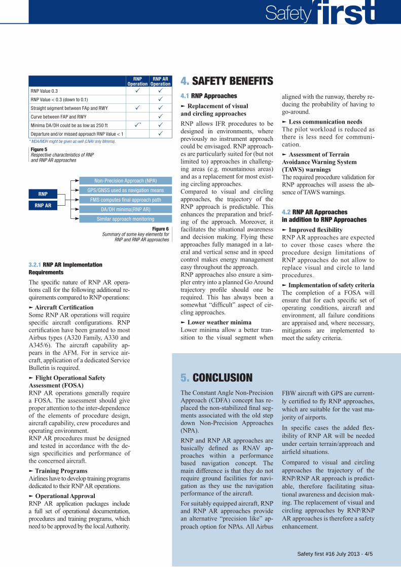
3.1 RNP approchesThe first approaches using RNAV equipment have been developed before the definition of RNP. For this historical reason RNP ap-proaches are commonly charted as RNAV (GNSS) or RNAV (GPS).
These RNP approaches are charac-terized by straight segments between the FAF and the runway (fig. 3).
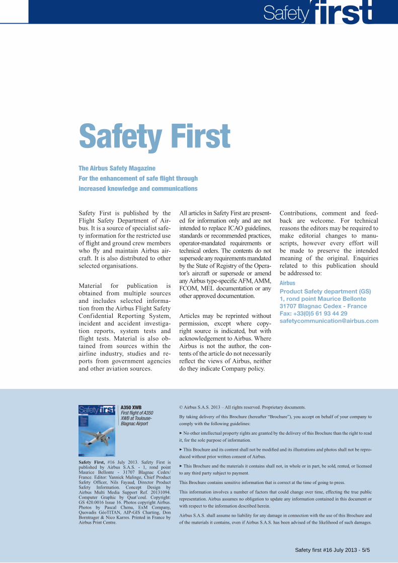
3.2 RNP AR ApproachesCompared to RNP approaches, where the segment between the FAF and the runway is straight, RNP with Authorization Required approaches might have “curved” final segments. These approaches are therefore colloquially called “curved approaches”. Further-more, RNP AR approaches allow reduced obstacle clearance com-pared to RNP approaches (fig. 4) RNP AR* approaches are charted as RNAV (RNP).
Figure 3Example of RNP approach chart
Figure 4Example of RNP
AR approach chart. * FAA terminology: RNP SAAAR (SpecialAircrew and Aircraft Authorisation Required)
Safety first #16 July 2013 - 3/5
Safety
3.2.1 RNP AR Implementation Requirements
The specific nature of RNP AR opera-tions call for the following additional re-quirements compared to RNP operations:
q Aircraft CertificationSome RNP AR operations will require specific aircraft configurations. RNP certification have been granted to most Airbus types (A320 Family, A330 and A345/6). The aircraft capability ap-pears in the AFM. For in service air-craft, application of a dedicated Service bulletin is required.
q Flight Operational Safety Assessment (FOSA)RNP AR operations generally require a FOSA. The assessment should give proper attention to the inter-dependence of the elements of procedure design, aircraft capability, crew procedures and operating environment.RNP AR procedures must be designed and tested in accordance with the de-sign specificities and performance of the concerned aircraft.
q Training ProgramsAirlines have to develop training programs dedicated to their RNP AR operations.
q Operational ApprovalRNP AR application packages include a full set of operational documentation, procedures and training programs, which need to be approved by the local Authority.
4. SAFETY BENEFITS4.1 RNP Approachesq Replacement of visual and circling approaches
RNP allows IFR procedures to be designed in environments, where previously no instrument approach could be envisaged. RNP approach-es are particularly suited for (but not limited to) approaches in challeng-ing areas (e.g. mountainous areas) and as a replacement for most exist-ing circling approaches.Compared to visual and circling approaches, the trajectory of the RNP approach is predictable. This enhances the preparation and brief-ing of the approach. Moreover, it facilitates the situational awareness and decision making. Flying these approaches fully managed in a lat-eral and vertical sense and in speed control makes energy management easy throughout the approach.RNP approaches also ensure a sim-pler entry into a planned Go Around trajectory profile should one be required. This has always been a somewhat “difficult” aspect of cir-cling approaches.
q Lower weather minimaLower minima allow a better tran-sition to the visual segment when
aligned with the runway, thereby re-ducing the probability of having to go-around.
q Less communication needsThe pilot workload is reduced as there is less need for communi-cation.
q Assessment of Terrain Avoidance Warning System (TAWS) warningsThe required procedure validation for RNP approaches will assess the ab-sence of TAWS warnings.
4.2 RNP AR Approaches in addition to RNP Approachesq Improved flexibilityRNP AR approaches are expected to cover those cases where the procedure design limitations of RNP approaches do not allow to replace visual and circle to land procedures.
q Implementation of safety criteria The completion of a FOSA will ensure that for each specific set of operating conditions, aircraft and environment, all failure conditions are appraised and, where necessary, mitigations are implemented to meet the safety criteria.
FbW aircraft with GPS are current-ly certified to fly RNP approaches, which are suitable for the vast ma-jority of airports.
In specific cases the added flex-ibility of RNP AR will be needed under certain terrain/approach and airfield situations.
Compared to visual and circling approaches the trajectory of the RNP/RNP AR approach is predict-able, therefore facilitating situa-tional awareness and decision mak-ing. The replacement of visual and circling approaches by RNP/RNP AR approaches is therefore a safety enhancement.
5. CONCLuSIONThe Constant Angle Non-Precision Approach (CDFA) concept has re-placed the non-stabilized final seg-ments associated with the old step down Non-Precision Approaches (NPA).
RNP and RNP AR approaches are basically defined as RNAV ap-proaches within a performance based navigation concept. The main difference is that they do not require ground facilities for navi-gation as they use the navigation performance of the aircraft.
For suitably equipped aircraft, RNP and RNP AR approaches provide an alternative “precision like” ap-proach option for NPAs. All Airbus
Non-Precision Approach (NPA)
Similar approach monitoring
GPS/GNSS used as navigation means
DA/DH minima(RNP AR)
FMS computes final approach path
* MDA/MDH might be given as well (LNAV only Minima).
RNP Operation
RNP AR Operation
RNP Value 0.3 P PRNP Value < 0.3 (down to 0.1) PStraight segment between FAp and RWY P PCurve between FAP and RWY PMinima DA/DH could be as low as 250 ft P* PDeparture and/or missed approach RNP Value < 1 P
RNP AR
RNP
Figure 5Respective characteristics of RNP and RNP AR approaches
Figure 6Summary of some key elements for
RNP and RNP AR approaches
Safety first #16 July 2013 - 4/5
The Airbus Safety Magazine
Subscription FormTo be sent back to
AIRBUS FLIGHT SAFETY OFFICEFax: 33 (0)5 61 93 44 29Mail to: [email protected]
Name . . . . . . . . . . . . . . . . . . . . . . . . . . . . . . . . . . . . . . . . . . . . . . . . . . . . . . . . . . . . . . . . . . . . . . . . . . . . . . . . . . . . . . . . .
Surname . . . . . . . . . . . . . . . . . . . . . . . . . . . . . . . . . . . . . . . . . . . . . . . . . . . . . . . . . . . . . . . . . . . . . . . . . . . . . . . . . . . . . . .
Job title/Function. . . . . . . . . . . . . . . . . . . . . . . . . . . . . . . . . . . . . . . . . . . . . . . . . . . . . . . . . . . . . . . . . . . . . . . . . . . . . . . . .
Company/Organization. . . . . . . . . . . . . . . . . . . . . . . . . . . . . . . . . . . . . . . . . . . . . . . . . . . . . . . . . . . . . . . . . . . . . . . . . . . . .
Address . . . . . . . . . . . . . . . . . . . . . . . . . . . . . . . . . . . . . . . . . . . . . . . . . . . . . . . . . . . . . . . . . . . . . . . . . . . . . . . . . . . . . . . .
. . . . . . . . . . . . . . . . . . . . . . . . . . . . . . . . . . . . . . . . . . . . . . . . . . . . . . . . . . . . . . . . . . . . . . . . . . . . . . . . . . . . . . . . . . . . . .
. . . . . . . . . . . . . . . . . . . . . . . . . . . . . . . . . . . . . . . . . . . . . . . . . . . . . . . . . . . . . . . . . . . . . . . . . . . . . . . . . . . . . . . . . . . . . .
Post/Zip Code . . . . . . . . . . . . . . . . . . . . . . . . . . . . . . . . . . . . . . . . . . . . . . . . . . . . . . . . . . . . . . . . . . . . . . . . . . . . . . . . . . .
Country . . . . . . . . . . . . . . . . . . . . . . . . . . . . . . . . . . . . . . . . . . . . . . . . . . . . . . . . . . . . . . . . . . . . . . . . . . . . . . . . . . . . . . . .
Telephone . . . . . . . . . . . . . . . . . . . . . . . . . . . . . . . . . . . . . . . . . . . . . . . . . . . . . . . . . . . . . . . . . . . . . . . . . . . . . . . . . . . . . .
Cell phone . . . . . . . . . . . . . . . . . . . . . . . . . . . . . . . . . . . . . . . . . . . . . . . . . . . . . . . . . . . . . . . . . . . . . . . . . . . . . . . . . . . . . .
Fax . . . . . . . . . . . . . . . . . . . . . . . . . . . . . . . . . . . . . . . . . . . . . . . . . . . . . . . . . . . . . . . . . . . . . . . . . . . . . . . . . . . . . . . . . . .
E-mail . . . . . . . . . . . . . . . . . . . . . . . . . . . . . . . . . . . . . . . . . . . . . . . . . . . . . . . . . . . . . . . . . . . . . . . . . . . . . . . . . . . . . . . . . . . . . . . . . .(Mandatory for both digital and paper copies)
Please send me the digital copy* PPlease send me the paper copy* P (Please note that paper copies
will only be forwardedto professional addresses)
* Please tick the appropriate case
Safety
Safety FirstThe Airbus Safety Magazine
For the enhancement of safe flight through
increased knowledge and communications
Safety First is published by the Flight Safety Department of Air-bus. It is a source of specialist safe-ty information for the restricted use of flight and ground crew members who fly and maintain Airbus air-craft. It is also distributed to other selected organisations.
Material for publication is obtained from multiple sources and includes selected informa-tion from the Airbus Flight Safety Confidential Reporting System, incident and accident investiga-tion reports, system tests and flight tests. Material is also ob-tained from sources within the airline industry, studies and re-ports from government agencies and other aviation sources.
All articles in Safety First are present-ed for information only and are not intended to replace ICAO guidelines, standards or recommended practices, operator-mandated requirements or technical orders. The contents do not supersede any requirements mand ated by the State of Registry of the Opera-tor’s aircraft or supersede or amend any Airbus type-specific AFM, AMM, FCOM, MEL documentation or any other approved documentation.
Articles may be reprinted without permission, except where copy-right source is indicated, but with acknowledgement to Airbus. Where Airbus is not the author, the con-tents of the article do not necessarily reflect the views of Airbus, neither do they indicate Company policy.
Contributions, comment and feed-back are welcome. For technical reasons the editors may be required to make editorial changes to manu-scripts, however every effort will be made to preserve the intended meaning of the original. Enquiries related to this publication should be addressed to:
AirbusProduct Safety department (GS)1, rond point Maurice Bellonte31707 Blagnac Cedex - FranceFax: +33(0)5 61 93 44 [email protected]
Safety First, #16 July 2013. Safety First is published by Airbus S.A.S. - 1, rond point Maurice Bellonte - 31707 Blagnac Cedex/France. Editor: Yannick Malinge, Chief Product Safety Officer, Nils Fayaud, Director Product Safety Information. Concept Design by Airbus Multi Media Support Ref. 20131094. Computer Graphic by Quat’coul. Copyright: GS 420.0016 Issue 16. Photos copyright Airbus. Photos by Pascal Chenu, ExM Company, Quovadis GéoTITAN, AIP-GIS Charting, Don Borntrager & Nico Karres. Printed in France by Airbus Print Centre.
© Airbus S.A.S. 2013 – All rights reserved. Proprietary documents.
By taking delivery of this Brochure (hereafter “Brochure”), you accept on behalf of your company to
comply with the following guidelines:
3 No other intellectual property rights are granted by the delivery of this Brochure than the right to read
it, for the sole purpose of information.
3 This Brochure and its content shall not be modified and its illustrations and photos shall not be repro-
duced without prior written consent of Airbus.
3 This Brochure and the materials it contains shall not, in whole or in part, be sold, rented, or licensed
to any third party subject to payment.
This Brochure contains sensitive information that is correct at the time of going to press.
This information involves a number of factors that could change over time, effecting the true public
representation. Airbus assumes no obligation to update any information contained in this document or
with respect to the information described herein.
Airbus S.A.S. shall assume no liability for any damage in connection with the use of this Brochure and
of the materials it contains, even if Airbus S.A.S. has been advised of the likelihood of such damages.
A350 XWBFirst flight of A350 XWB at Toulouse- Blagnac Airport
Safety 27Issue 16 | JULY 2013The Airbus Safety Magazine
Safety first #16 July 2013 - 5/5

![Modern Navigation. [Approaches] - WordPress.com14. Bill Royce, RNAV/RNP Operations & VNAV Approaches, Boeing 15. CAP 773, Flying RNAV (GNSS) Approaches in Private and General Aviation](https://img.pdfslide.net/doc/110x75/5e7ba9453df4c81fd0241750/modern-navigation-approaches-14-bill-royce-rnavrnp-operations-vnav.jpg)