Embed Size (px)
Citation preview
Operating Manual
BA14105E/07.00/AS/pH170-296_4
pH / Redox Monitors
pH 170pH 296
pH 170
pH 296
General informations
106
Accuracy when going to press
The use of advanced technology and the high quality standard of our instrumentsare the result of continuous development. This may result in differences betweenthis operating manual and your meter. We cannot guarantee that there areabsolutely no errors in this manual. We are sure you will understand that we cannotaccept any legal claims resulting from the data, figures or descriptions. Theinformation in this manual is subject to change without any notice.
Warranty
The designated meter is covered by a warranty of 2 years from the date ofpurchase.The meter warranty extends to manufacturing faults that are determined within theperiod of warranty. The warranty excludes components that are replaced duringmaintenance.
The warranty claim extends to restoring the meter to readiness for use but not,however, to any further claim for damages. Improper handling or unauthorizedopening of the meter invalidates any warranty claim.
To ascertin the warranty liability, return the meter and proof of purchase togetherwith the date of purchase freight paid or prepaid.
Copyright
¸ Weilheim 2000, WTW GmbHReprinting – even in the form of excerpts – is only allowed with the explicit writtenauthorization of WTW GmbH, Weilheim.Printed in Germany.
Safety Instructions S+ ����S+ ���
107
Please read these safety instructions carefully before installing theinstrument!
This instrument is built according to the safety rules for electronic measuringinstruments and left the factory in a safe and secure condition from a safetyengineering aspect (IEC 1010).
The smooth functioning and operational safety of the equipment can only beguaranteed by following the general safety precautions applicable and the specialsafety instructions given in this operating manual.
-� Before switching on the instrument, ensure that the operational voltagespecified for the instrument correspond to the power supply.(specification of the ranges of the voltage supply).
�-� This instrument may only be operated using accessories that comply with the
specifications in the chapter "Technical Data" in this operating manual.The manufacturer accepts no liability for damage resulting from the use ofunsuitable accessories.
�-� The trouble-free function and operational safety of the instrument can only be
guaranteed by following the climate conditions specified in the chapter"Technical data" in this operating manual.
�-� Opening of the instrument as well as adjustment and maintenance or repair
work must only be performed by personnel authorized by WTW. Depending onthe severity, contravention can lead to loss of warranty.
�-� If safe operation is no longer possible, the equipment must be taken out of
service and secured against inadvertent operation by labeling with warningsigns.
�
-� The safety of the user can be affected by the instrument if, for example,� the instrument is visibly damaged,� the instrument no longer operates as prescribed,� the instrument has been stored under adverse conditions for a lengthy
period of time,� the instrument was exposed to adverse transport conditions.
Basically, if you are in any doubt, please return the instrument for repair ormaintenance to the manufacturer of the equipment,"Wissenschaftlich-Technische-Werkstätten GmbH".
S+ ����S+ ���
Contents
108
Safety instructions .............................................................................................. 107
Description ........................................................................................................... 111Front views ............................................................................................................ 111Control panel ......................................................................................................... 112
Display .............................................................................................................. 112Display messages ............................................................................................. 113Keyboard ........................................................................................................... 115Operating instructions ....................................................................................... 115
Operating levels ..................................................................................................... 116
Installation ........................................................................................................... 116General instructions ............................................................................................... 116Power supply ......................................................................................................... 116"SENS-CHECK" connection ................................................................................... 117REC 1 / REC 2 connections .................................................................................. 117K1 / K2 (relay contacts) ......................................................................................... 117RS 485 digital interace (RS option) ....................................................................... 118Installation instructions for the pH 170 .................................................................. 119
Terminal assignment ......................................................................................... 119Connecting the SenoLyt 650.............................................................................. 121Connecting the SenoLyt 690 or SensoLyt 700................................................... 123Connecting other sensors ................................................................................. 124Connecting other sensors with an external temperature sensore...................... 125Connecting a high-resistance probe with external temperature probe(Example: NTC) ................................................................................................. 126Connecting a high-resistance probe with external temperature probe(Example: PT 100 / PT 1000) ............................................................................ 127Connecting a InPro® 4200.................................................................................. 128Connecting the KI/pH 170 terminal box ............................................................. 129Connecting the KI/S terminal box ...................................................................... 131Wiring of KI/S ..................................................................................................... 132Connecting the KI/S connection box to the LF 170 using the K 160plug and EK/AG cable........................................................................................ 133
Installation instructions for the pH 296 .................................................................. 134Terminal assignment ......................................................................................... 134Connecting the SenoLyt 650.............................................................................. 136Connecting the SensoLyt 690 or SensoLyt 700 ................................................ 138Connecting measuring chains with an external temperature sensor ................. 140Connecting a InPro® 4200.................................................................................. 142Connecting the terminal box KI/pH 170 ............................................................. 143
Contents S+ ����S+ ���
109
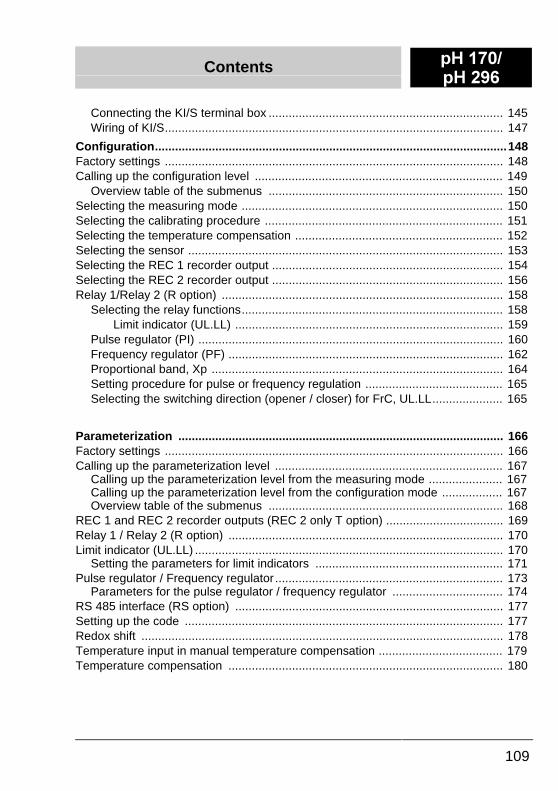
Connecting the KI/S terminal box ...................................................................... 145Wiring of KI/S..................................................................................................... 147
Configuration.........................................................................................................148Factory settings ..................................................................................................... 148Calling up the configuration level .......................................................................... 149
Overview table of the submenus ...................................................................... 150Selecting the measuring mode .............................................................................. 150Selecting the calibrating procedure ....................................................................... 151Selecting the temperature compensation .............................................................. 152Selecting the sensor .............................................................................................. 153Selecting the REC 1 recorder output ..................................................................... 154Selecting the REC 2 recorder output ..................................................................... 156Relay 1/Relay 2 (R option) .................................................................................... 158
Selecting the relay functions.............................................................................. 158Limit indicator (UL.LL) ................................................................................ 159
Pulse regulator (PI) ........................................................................................... 160Frequency regulator (PF) .................................................................................. 162Proportional band, Xp ....................................................................................... 164Setting procedure for pulse or frequency regulation ......................................... 165Selecting the switching direction (opener / closer) for FrC, UL.LL..................... 165
Parameterization ................................................................................................. 166Factory settings ..................................................................................................... 166Calling up the parameterization level .................................................................... 167
Calling up the parameterization level from the measuring mode ...................... 167Calling up the parameterization level from the configuration mode .................. 167Overview table of the submenus ...................................................................... 168
REC 1 and REC 2 recorder outputs (REC 2 only T option) ................................... 169Relay 1 / Relay 2 (R option) .................................................................................. 170Limit indicator (UL.LL) ............................................................................................ 170
Setting the parameters for limit indicators ........................................................ 171Pulse regulator / Frequency regulator .................................................................... 173
Parameters for the pulse regulator / frequency regulator ................................. 174RS 485 interface (RS option) ................................................................................ 177Setting up the code ............................................................................................... 177Redox shift ............................................................................................................ 178Temperature input in manual temperature compensation ..................................... 179Temperature compensation .................................................................................. 180
S+ ����S+ ���
Contents
110
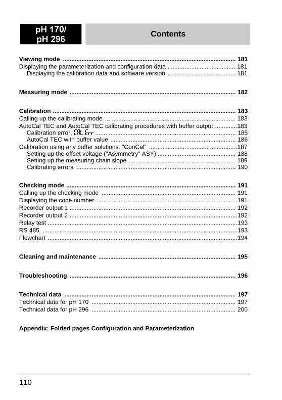
Viewing mode ...................................................................................................... 181Displaying the parameterization and configuration data ........................................ 181
Displaying the calibration data and software version ........................................ 181
Measuring mode .................................................................................................. 182
Calibration ............................................................................................................ 183Calling up the calibrating mode ............................................................................. 183AutoCal TEC and AutoCal TEC calibrating procedures with buffer output .............183
Calibration error, ��/ �)) ................................................................................... 185AutoCal TEC with buffer value .......................................................................... 186
Calibration using any buffer solutions: "ConCal" ....................................................187Setting up the offset voltage ("Asymmetry" ASY) .............................................. 188Setting up the measuring chain slope ............................................................... 189Calibrating errors .............................................................................................. 190
Checking mode .................................................................................................... 191Calling up the checking mode ............................................................................... 191Displaying the code number ...................................................................................191Recorder output 1 .................................................................................................. 192Recorder output 2 ...................................................................................................192Relay test ................................................................................................................193RS 485 ...................................................................................................................193Flowchart ................................................................................................................194
Cleaning and maintenance ................................................................................. 195
Troubleshooting .................................................................................................. 196
Technical data ..................................................................................................... 197Technical data for pH 170 ..................................................................................... 197Technical data for pH 296 ..................................................................................... 200
Appendix: Folded pages Configuration and Parameterization
Description S+ ����S+ ���
111
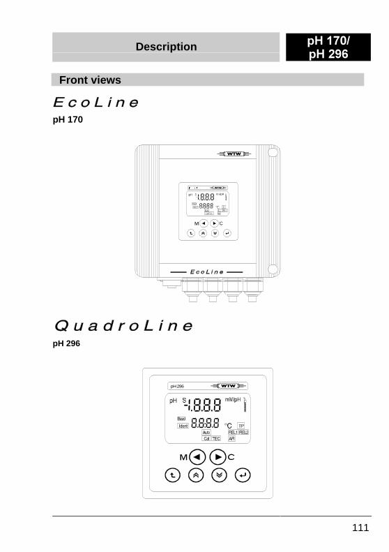
Front views
pH 170
S+ ���
pH 296
pH296
S+ ����S+ ���
Description
112
Control panel
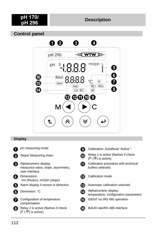
Display
pH measuring mode Calibration: AutoRead “Active “
Slope/ Measuring chain Relay 1 is active (flashes if check(-, -�) is active)
Alphanumeric display:measured value, slope, asymmetry,user interface
Calibration procedure with technicalbuffers selected
Dimensions: mV (Redox), mV/pH (slope)
Calibration mode
Alarm display if sensor is defective Automatic calibration selected
Dimension: °C Alphanumeric display:temperature, configuration parameters
Configuration of temperaturecompensation
IDENT no./RS 485 operation
Relay 2 is active (flashes if check(-, -�) is active)
BAUD rate/RS 485 interface
Description S+ ����S+ ���
113
Display messages
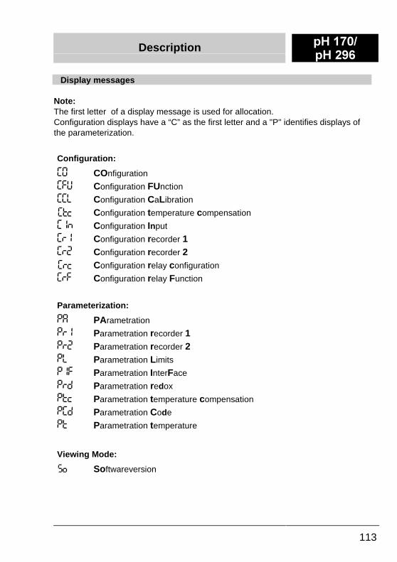
Note:The first letter of a display message is used for allocation.Configuration displays have a “C” as the first letter and a "P" identifies displays ofthe parameterization.
Configuration:
�I COnfiguration
��6 Configuration FUnction
��/ Configuration CaLibration
Configuration temperature compensation
�=' Configuration Input
�)� Configuration recorder 1�)� Configuration recorder 2
Configuration relay configuration
�)� Configuration relay Function
Parameterization:
-� PArametration
-)� Parametration recorder 1-)� Parametration recorder 2-/ Parametration Limits
-� Parametration InterFace
-)& Parametration redox
-*8 Parametration temperature compensation
-�& Parametration Code
-* Parametration temperature
Viewing Mode:
Softwareversion
S+ ����S+ ���
Description
114
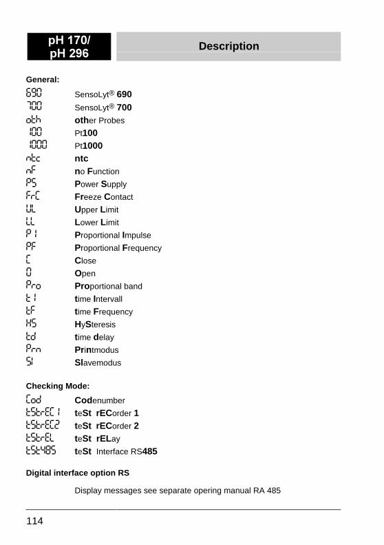
General:
��� SensoLyt® 690��� SensoLyt® 700(*< other Probes
��� Pt100���� Pt1000'*8 ntc'� no Function
-� Power Supply
�)� Freeze Contact
6/ Upper Limit
// Lower Limit
- Proportional Impulse
-� Proportional Frequency
� Close
I Open
-)( Proportional band
* time Intervall
*� time Frequency
�� HySteresis
*& time delay
-)' Printmodus
�, Slavemodus
Checking Mode:
�(& Codenumber
*@*)9�� teSt rECorder 1*@*)9�� teSt rECorder 2*@*)9/ teSt rELay
*@*��� teSt Interface RS485
Digital interface option RS
Display messages see separate opering manual RA 485
Description S+ ����S+ ���
115
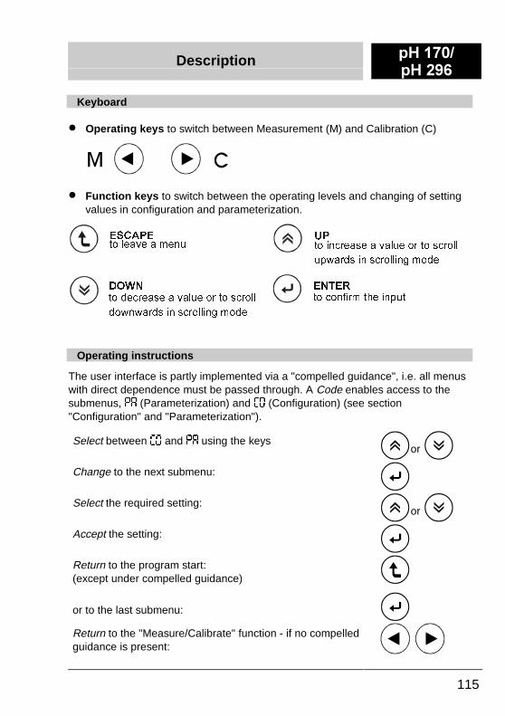
Keyboard
�� Operating keys to switch between Measurement (M) and Calibration (C)
�� Function keys to switch between the operating levels and changing of settingvalues in configuration and parameterization.
Operating instructions
The user interface is partly implemented via a "compelled guidance", i.e. all menuswith direct dependence must be passed through. A Code enables access to thesubmenus, -� (Parameterization) and �� (Configuration) (see section"Configuration" and "Parameterization").
Select between �� and -� using the keysor
Change to the next submenu:
Select the required setting:or
Accept the setting:
Return to the program start:(except under compelled guidance)
or to the last submenu:
Return to the "Measure/Calibrate" function - if no compelledguidance is present:
(6&$3(WR�OHDYH�D�PHQX
(17(5
WR�FRQILUP�WKH�LQSXW
83WR�LQFUHDVH�D�YDOXH�RU�WR�VFUROO
XSZDUGV�LQ�VFUROOLQJ�PRGH
'2:1
WR�GHFUHDVH�D�YDOXH�RU�WR�VFUROO
GRZQZDUGV�LQ�VFUROOLQJ�PRGH
S+ ����S+ ���
Description
116
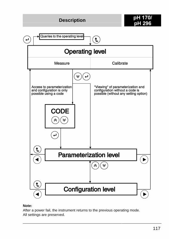
Operating levelsThe instrument functions are incorporated in three levels consecutively structuredto ensure a clear and transparent structure.This structure ensures that the user is provided with an instrument that, although ithas universal options, can still be set so that unauthorized actions do not interferewith the reliable measuring mode.
Operating level:The configuration and parameterization can be interrogated in the operating levelwithout having to enter a code while the measuring mode continues to run.However, the settings cannot be changed. The Measure and Calibrate operatingmodes can be selected without any access restrictions.
Parameterization level:The measuring ranges, limiting values, etc. are entered here. Access is protectedby a code.
Configuration level:The functions of the monitor are allocated in this level.The configuration is performed after the installation of the instrument, mainly on theinitial commissioning. Access is also protected by a code.
Description S+ ����S+ ���
117
Note:After a power fail, the instrument returns to the previous operating mode.All settings are preserved.
S+ ����S+ ���
Installation
116
General instructions��� Instruments to be installed in the field (pH 170) must be equipped with a
protective cover (see WTW accessories).�� After installing the pH 170, close the cover to ensure compliance with the
IP66 standard.�� Inputs/outputs require no additional lightning protection.
The measures required for lightning protection are already incorporated in themonitor and any existing lightning protection measures can be used in addition.
�� The PG screws of the pH 170 are designed for cable diameters of 10 to14 mm.Unused cable feed-throughs (PG screws) are equipped with a sealing plug toensure compliance with the IP66 standard.
Power supply
Only allow qualified electricians to perform the installation as itinvolves a line voltage that could endanger life.A bipolar disconnection option between instrument and mains isprovided (e.g. a fuse)!
Depending on the version, the instruments are designed for 230 VAC, 115 VAC,24 VAC or 24 VDC. The line voltage is printed on the nameplate. Always checkthat the correct line voltage is applied before commissioning the instrument.
An incorrect line voltage can result in damage to theinstrument!
In instruments with a 24 VDC module, observe the following: Only operate instruments with a voltage source that fulfills the requirements forSELV (Safety Extra Low Voltage with enhanced insulation against dangerousvoltages) in accordance with EN 60950.Without an interface, the requirements should fulfill EN 61010-1.
All instruments of the "170/296" series are constructed in accordance with safetyclass II, i.e. no protective earth conductor is required.
Do not feed the protective earth conductor into the instrument orconnect it to an instrument terminal or to a supply line!Only authorized WTW technicians are allowed to change theinstrument fuse.
Installation S+ ����S+ ���
117
"SENS-CHECK" connection
The "SENS-CHECK" relay is designed as a closing contact that is electricallyisolated from the instrument; it is then always active (= closed) if a sensor erroroccurs.This message is also output on the display.Sensor errors in the switching station are displayed using the relay.
Note:The relay contact should only be loaded with a maximum of 250 VAC / 5A up to amaximum of 150 W.
REC 1 / REC 2 connections
The REC 1 (pH/mV) and REC 2 (temperature) current outputs can be configuredas follows:
�� 0 to 20 mA
�� 4 to 20 mAIf terminals with a common earth are used, ensure the exact polarity of the directionof the current flow (+ / – ). It involves active current sources that require no externalcurrent source!
Do not use an external current source as this can lead tomalfunction of the current outputs!
Maximum load of 600 Ohm.
K1 / K2 (relay contacts)
The K1 and K2 relay contacts are designed as potential-free closers (makecontacts).These contacts can also be configured as openers (break contacts) via theconfiguration level. The assignment of the relay to the corresponding functions isundertaken by the software configuration.
Note:The contacts are designed for 250 VAC / 5A with, however, a maximum of 150 W.
S+ ����S+ ���
Installation
118
RS 485 digital interface (RS option)
The RS 485 interface operates with differential levels that are not susceptible tointerference. In this way, cable lengths of up to 1 km long can be implemented. Theinstruments are connected via a 2-wire line. A twisted 3-wire line is recommendedfor greater lengths or a larger number of instruments; the third line is used as areference potential (GND), to compensate for any possible differences in potentialthat occur.
Terminate every bus with a resistor using the software (see Parameterizing).
The last device on the bus must provide the terminating resistor, i.e. inparameterizing in the menu item -�, the last device must have the terminationconnected additionally within the bus connection (*) = termination) anddisconnected ('(*) = no termination) in all other devices.
If only one device is used, this is also effectively the last device and the terminatingresistor must be connected (*)).
All other technical data and operating instructions are given in RS 485Operating Manual.
USA and Canada:Use the MCB 17x conduit box for the power supply and relay/alarmcontacts. Follow the installation instructions.
Installation pH 170
119
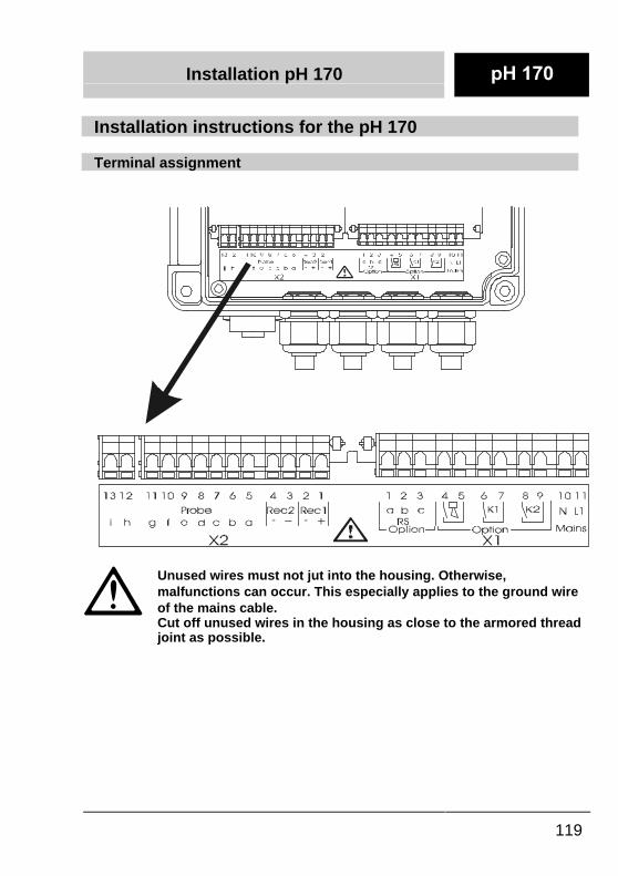
Installation instructions for the pH 170
Terminal assignment
�
Unused wires must not jut into the housing. Otherwise,malfunctions can occur. This especially applies to the ground wireof the mains cable.�Cut off unused wires in the housing as close to the armored threadjoint as possible.
Installation pH 170
120
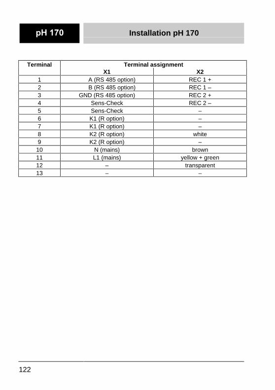
Terminal Terminal assignmentX1 X2
1 A (RS 485 option) REC 1 +2 B (RS 485 option) REC 1 –3 GND (RS 485 option) REC 2 +4 Sens-Check REC 2 –5 Sens-Check a (sensor)6 K1 (R option) b (sensor)7 K1 (R option) c (sensor)8 K2 (R option) d (sensor)9 K2 (R option) e (sensor)
10 N (mains) f (sensor)11 L1 (mains) g (sensor)12 – h (sensor)13 – i (sensor)
Note:For power supplies above 24 VDC, use the following wiring:L1 + 24 VN GND
Installation pH 170
121
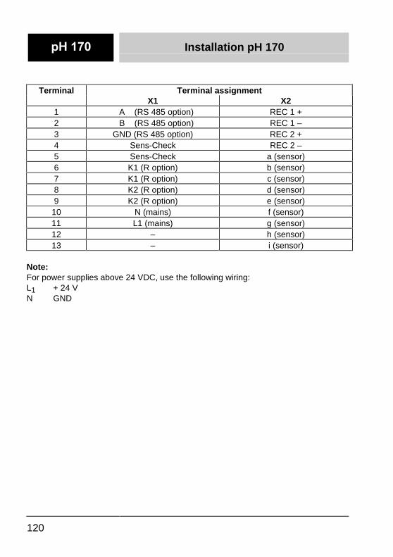
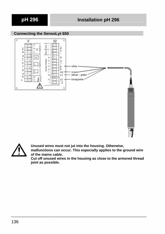
Connecting the SensoLyt 650
If a SensoLyt 650 is used, the Dip switch on the circuit board of the 170must be in the “ON“ position.
cba L1N
RSOption
Netz
Mains
Netz
MainsOption
K2K1
X1
13 12 11 1110 109 98 87 76 65 54 43 32 21 1
Dipschalter
ON
12 1110 9 8
brow
n
yello
w/g
reen
tran
spar
ent
whi
te
brow
n
yello
w/g
reen
tran
spar
ent
whi
te
�
Unused wires must not jut into the housing. Otherwise,malfunctions can occur. This especially applies to the ground wireof the mains cable.�Cut off unused wires in the housing as close to the armored threadjoint as possible.
Installation pH 170
122
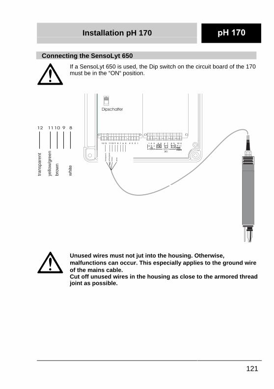
Terminal Terminal assignmentX1 X2
1 A (RS 485 option) REC 1 +2 B (RS 485 option) REC 1 –3 GND (RS 485 option) REC 2 +4 Sens-Check REC 2 –5 Sens-Check –6 K1 (R option) –7 K1 (R option) –8 K2 (R option) white9 K2 (R option) –
10 N (mains) brown11 L1 (mains) yellow + green12 – transparent13 – –
Installation pH 170
123
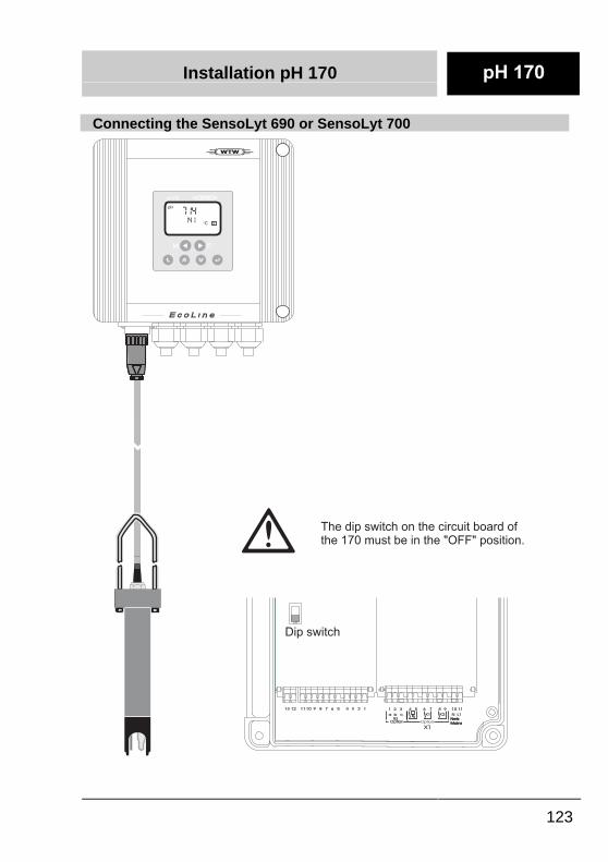
Connecting the SensoLyt 690 or SensoLyt 700
CCMM
pH 170pH 170
714141 °C
pH
TP
cba L1N
RSOption
Netz
Mains
Netz
MainsOption
K2K1
X1
13 12 11 1110 109 98 87 76 65 54 43 32 21 1
Dip switchOFF
The dip switch on the circuit board ofthe 170 must be in the "OFF" position.
Installation pH 170
124
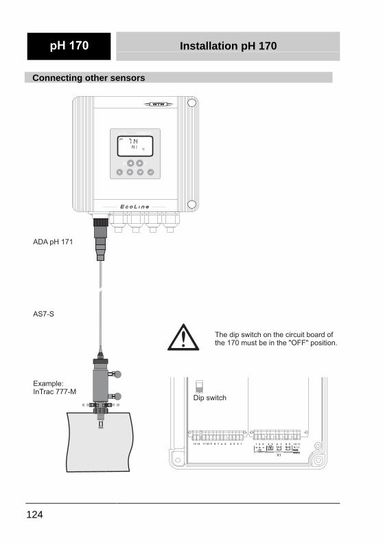
Connecting other sensors
cba L1N
RSOption
Netz
Mains
Netz
MainsOption
K2K1
X1
13 12 11 1110 109 98 87 76 65 54 43 32 21 1
Dip switchOFF
CCMM
pH 170pH 170
714141 °C
pH
TTPP
ADA pH 171
AS7-S
Example:InTrac 777-M
The dip switch on the circuit board ofthe 170 must be in the "OFF" position.
Installation pH 170
125
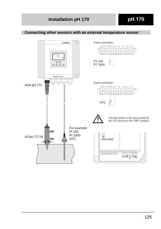
Connecting other sensors with an external temperature sensor
cba L1N
RSOption
Netz
Mains
Netz
MainsOption
K2K1
X1
13 12 11 1110 109 98 87 76 65 54 43 32 21 1
DipschalterOFF
The Dip switch on the circuit board ofthe 170 must be in the "OFF" postion.
CCMM
pH 170pH 170
714141 °C
pH
TP
ADA pH 171
InTrac 777-M
PT 100PT 1000
3-wire connection:
2-wire connection:
For example:Pt 100Pt 1000NTC
NTC
1312 1110 9 8 7 6 5 4 3 2 1
1312 1110 9 8 7 6 5 4 3 2 1
Installation pH 170
126
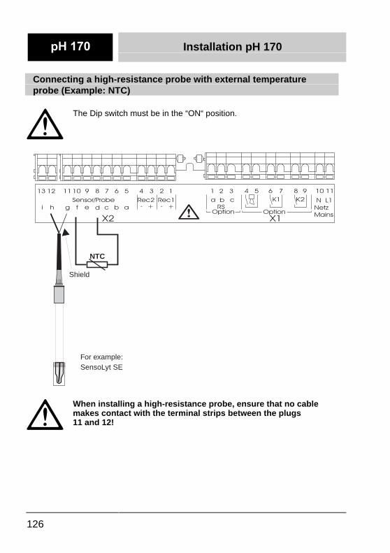
Connecting a high-resistance probe with external temperatureprobe (Example: NTC)
The Dip switch must be in the “ON“ position.
- + -
i h g f e d
cbaRec2 L1NRS
Option
Sensor/Probe Rec1
Netz
Mains
cOption
b a
+
K2K1
X2 X1
13 12 11 1110 109 98 87 76 65 54 43 32 21 1
For example:SensoLyt SE
NTC
Shield
When installing a high-resistance probe, ensure that no cablemakes contact with the terminal strips between the plugs11 and 12!
Installation pH 170
127
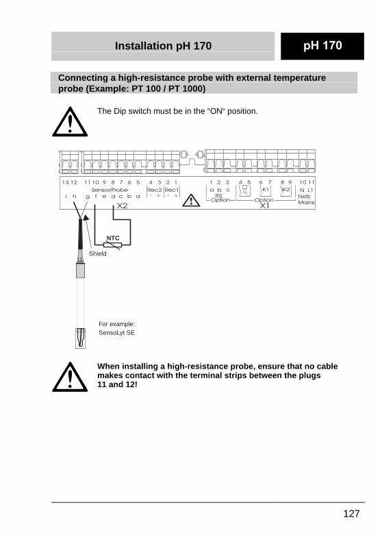
Connecting a high-resistance probe with external temperatureprobe (Example: PT 100 / PT 1000)
The Dip switch must be in the “ON“ position.
- + -
i h g f e d
cbaRec2 L1NRS
Option
Sensor/Probe Rec1
Netz
Mains
cOption
b a
+
K2K1
X2 X1
13 12 11 1110 109 98 87 76 65 54 43 32 21 1
For example:SensoLyt SE
NTC
Shield
When installing a high-resistance probe, ensure that no cablemakes contact with the terminal strips between the plugs11 and 12!
Installation pH 170
128
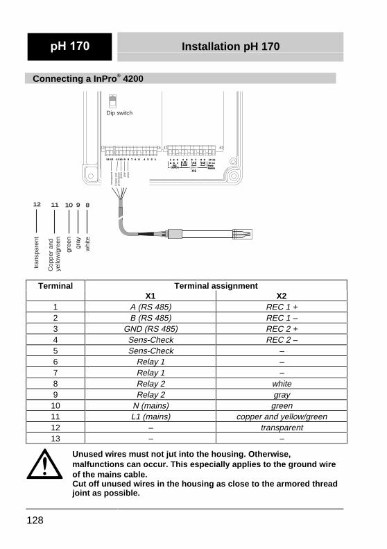
Connecting a InPro® 4200
cba L1NRS
OptionNetzMainsNetzMainsOption
K2K1
X1
13 12 11 1110 109 98 87 76 65 54 43 32 21 1
Dip switch
ON
gree
n
Cop
per
and
yello
w/g
reen
tran
spar
ent
whi
te
12 11 10 9 8
gray
Cop
per
and
yello
w/g
reen
tran
spar
ent
gree
n
whi
te
gray
Terminal Terminal assignmentX1 X2
1 A (RS 485) REC 1 +2 B (RS 485) REC 1 –3 GND (RS 485) REC 2 +4 Sens-Check REC 2 –5 Sens-Check –6 Relay 1 –7 Relay 1 –8 Relay 2 white9 Relay 2 gray
10 N (mains) green11 L1 (mains) copper and yellow/green12 – transparent13 – –
Unused wires must not jut into the housing. Otherwise,malfunctions can occur. This especially applies to the ground wireof the mains cable.Cut off unused wires in the housing as close to the armored threadjoint as possible.
Installation pH 170
129
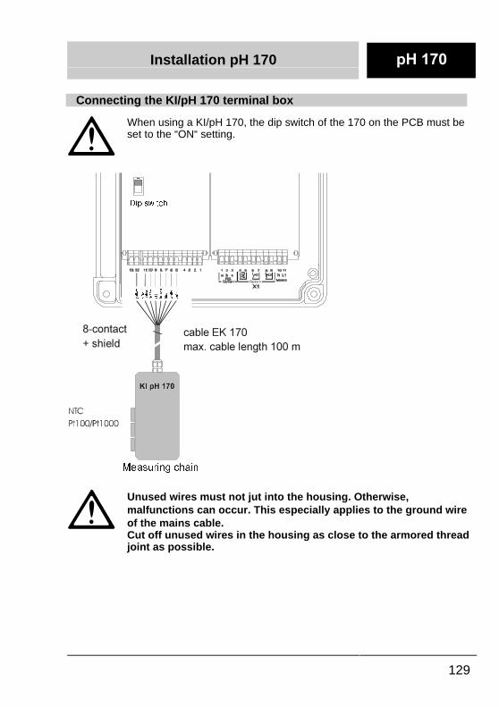
Connecting the KI/pH 170 terminal box
When using a KI/pH 170, the dip switch of the 170 on the PCB must beset to the “ON“ setting.
�
Unused wires must not jut into the housing. Otherwise,malfunctions can occur. This especially applies to the ground wireof the mains cable.�Cut off unused wires in the housing as close to the armored threadjoint as possible.
'LS�VZLWFK
FDEOH�(.����PD[��FDEOH�OHQJWK�����P
��FRQWDFW��VKLHOG
0HDVXULQJ�FKDLQ
21
VKLHOG
JUHHQ
JUD\��
UHG
\HOORZ
EURZQ
EOXH
ZKLWH
SLQN

Installation pH 170
130
Terminal Terminal assignmentX1 X2
1 A (RS 485 option) REC 1 +2 B (RS 485 option) REC 1 –3 GND (RS 485 option) REC 2 +4 Sens-Check REC 2 –5 Sens-Check pink6 K1 (R option) white7 K1 (R option) blue8 K2 (R option) brown9 K2 (R option) red
10 N (mains) green11 L1 (mains) gray + screen12 – yellow13 – –
Installation pH 170
131
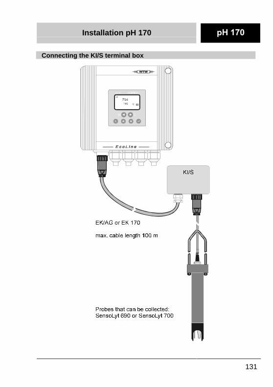
�Connecting the KI/S terminal box
��
.,�6
(.�$*�RU�(.�����
PD[��FDEOH�OHQJWK�����P�
3UREHV�WKDW�FDQ�EH�FROOHFWHG�6HQVR/\W�����RU�6HQVR/\W����
Installation pH 170
132
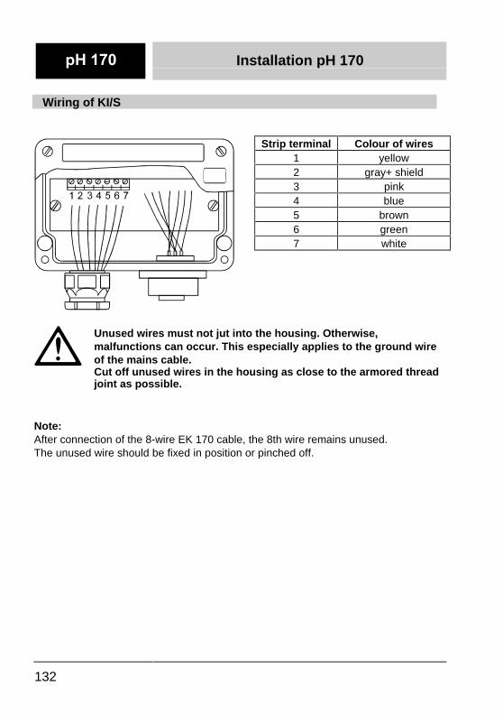
�Wiring of KI/S�
�
��
�
Unused wires must not jut into the housing. Otherwise,malfunctions can occur. This especially applies to the ground wireof the mains cable.�Cut off unused wires in the housing as close to the armored threadjoint as possible.
��Note:�After connection of the 8-wire EK 170 cable, the 8th wire remains unused.�The unused wire should be fixed in position or pinched off.
�Strip terminal �Colour of wires�1 �yellow�2 �gray+ shield�3 �pink�4 �blue�5 �brown�6 �green�7 �white
�
Installation pH 170
133
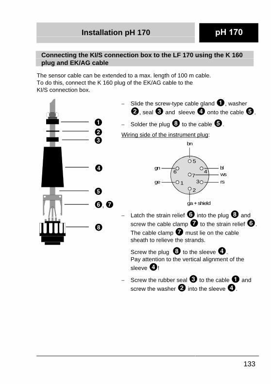
�Connecting the KI/S connection box to the LF 170 using the K 160plug and EK/AG cable�
�The sensor cable can be extended to a max. length of 100 m cable.�To do this, connect the K 160 plug of the EK/AG cable to the�KI/S connection box.�
�
-� Slide the screw-type cable gland , washer
, seal and sleeve onto the cable .�-� Solder the plug to the cable .��Wiring side of the instrument plug: �
�
gn
1
6
5
47
3
2
bn
wsbl
ge
ga + shield
rs
�-� Latch the strain relief into the plug and
screw the cable clamp to the strain relief .
The cable clamp must lie on the cablesheath to relieve the strands.
�� Screw the plug to the sleeve .
Pay attention to the vertical alignment of the
sleeve !�-� Screw the rubber seal to the cable and
screw the washer into the sleeve .
Installation pH 296
134
Installation instructions for the pH 296
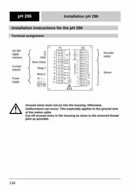
Terminal assignment
�
Unused wires must not jut into the housing. Otherwise,malfunctions can occur. This especially applies to the ground wireof the mains cable.�Cut off unused wires in the housing as close to the armored threadjoint as possible.
$%
*1'
6HQV�&KHFN
56����
GLJLWDO
LQWHUIDFH
&RQWDFW�
RXWSXWV
5HFRUGHU
RXWSXW
6HQVRU
3RZHU�
VXSSO\
5HOD\��
5HOD\��
1�������
/�����������
$&���'&
Installation pH 296
135
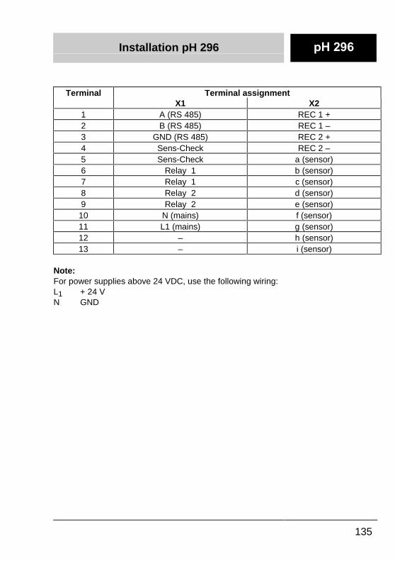
Terminal Terminal assignmentX1 X2
1 A (RS 485) REC 1 +2 B (RS 485) REC 1 –3 GND (RS 485) REC 2 +4 Sens-Check REC 2 –5 Sens-Check a (sensor)6 Relay 1 b (sensor)7 Relay 1 c (sensor)8 Relay 2 d (sensor)9 Relay 2 e (sensor)
10 N (mains) f (sensor)11 L1 (mains) g (sensor)12 – h (sensor)13 – i (sensor)
Note:For power supplies above 24 VDC, use the following wiring:L1 + 24 VN GND
Installation pH 296
136
Connecting the SensoLyt 650
�
��
�
��
�
�
�
�
�
�
�� �
�
�
�
�
�
��
�
��
�
��
��
;�;�
�
Unused wires must not jut into the housing. Otherwise,malfunctions can occur. This especially applies to the ground wireof the mains cable.�Cut off unused wires in the housing as close to the armored threadjoint as possible.
Installation pH 296
137
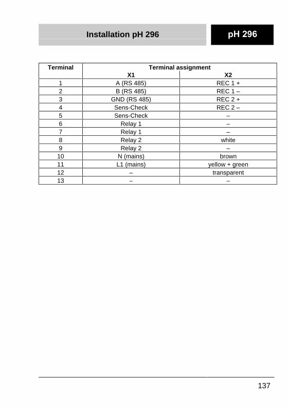
Terminal Terminal assignmentX1 X2
1 A (RS 485) REC 1 +2 B (RS 485) REC 1 –3 GND (RS 485) REC 2 +4 Sens-Check REC 2 –5 Sens-Check –6 Relay 1 –7 Relay 1 –8 Relay 2 white9 Relay 2 –
10 N (mains) brown11 L1 (mains) yellow + green12 – transparent13 – –
Installation pH 296
138
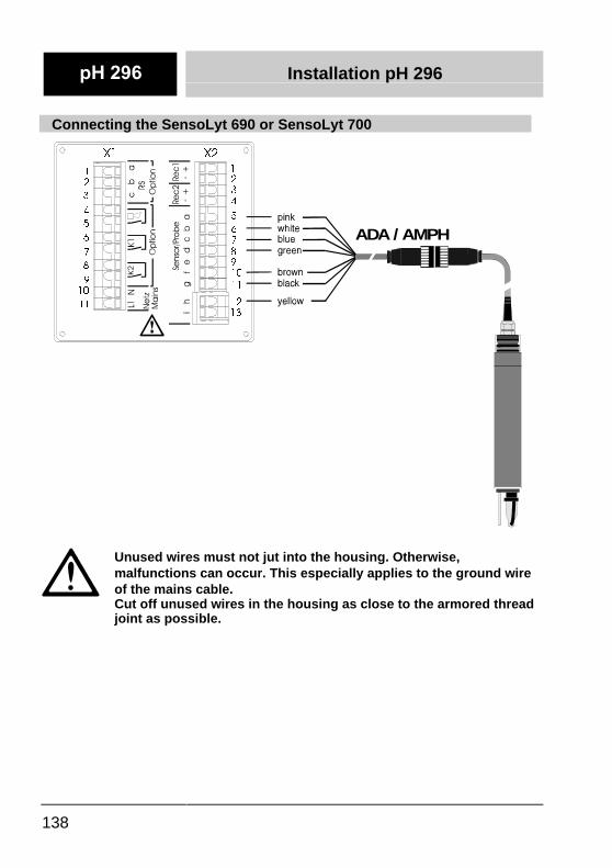
Connecting the SensoLyt 690 or SensoLyt 700
�
��
�
��
�
�
�
�
�
�
�� �
�
�
�
�
�
��
�
��
�
��
��
;�;�
ADA / AMPH
�
Unused wires must not jut into the housing. Otherwise,malfunctions can occur. This especially applies to the ground wireof the mains cable.�Cut off unused wires in the housing as close to the armored threadjoint as possible.
Installation pH 296
139
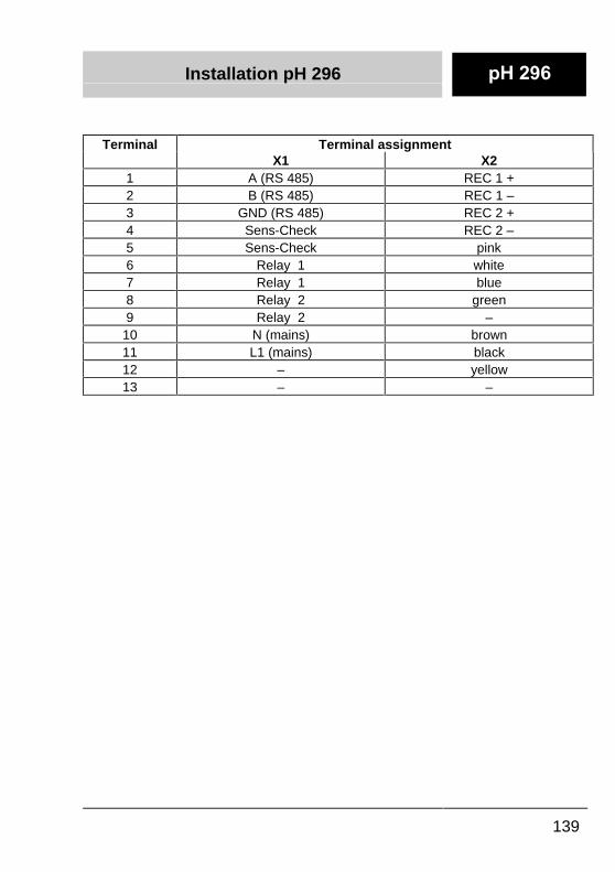
Terminal Terminal assignmentX1 X2
1 A (RS 485) REC 1 +2 B (RS 485) REC 1 –3 GND (RS 485) REC 2 +4 Sens-Check REC 2 –5 Sens-Check pink6 Relay 1 white7 Relay 1 blue8 Relay 2 green9 Relay 2 –
10 N (mains) brown11 L1 (mains) black12 – yellow13 – –
Installation pH 296
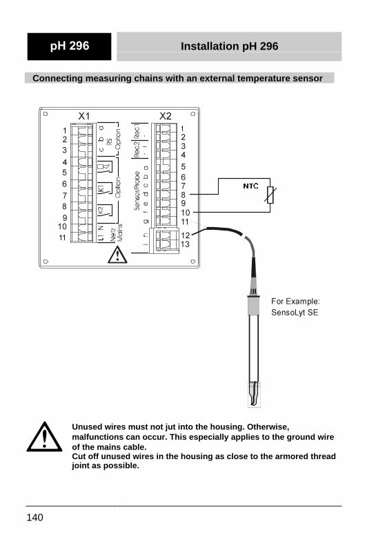
140
Connecting measuring chains with an external temperature sensor
�
Unused wires must not jut into the housing. Otherwise,malfunctions can occur. This especially applies to the ground wireof the mains cable.�Cut off unused wires in the housing as close to the armored threadjoint as possible.
17&
)RU�([DPSOH�6HQVR/\W�6(
�
��
�
��
�
�
�
�
�
�
�� �
�
�
�
�
�
��
�
��
�
����
;�;�
Installation pH 296
141
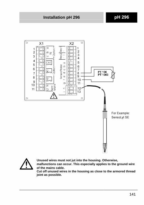
�
Unused wires must not jut into the housing. Otherwise,malfunctions can occur. This especially applies to the ground wireof the mains cable.�Cut off unused wires in the housing as close to the armored threadjoint as possible.
)RU�([DPSOH�6HQVR/\W�6(
37����37�����
�
��
�
��
�
�
�
�
�
�
�� �
�
�
�
�
�
��
�
��
�
����
;�;�

Installation pH 296
142
Connecting the terminal box KI/pH 170
�
Unused wires must not jut into the housing. Otherwise,malfunctions can occur. This especially applies to the ground wireof the mains cable.�Cut off unused wires in the housing as close to the armored threadjoint as possible.
SLQN
.,�S+����
ZKLWHEOXHJUHHQUHG
EURZQJUD\�
\HOORZ
��FRQWDFW
��VFUHHQ
17&
3W����3W����
0HDVXULQJ
FKDLQ
�
��
�
��
�
�
�
�
�
�
�� �
�
�
�
�
�
��
�
��
�
��
��
;�;�
VFUHHQ
Installation pH 296
143
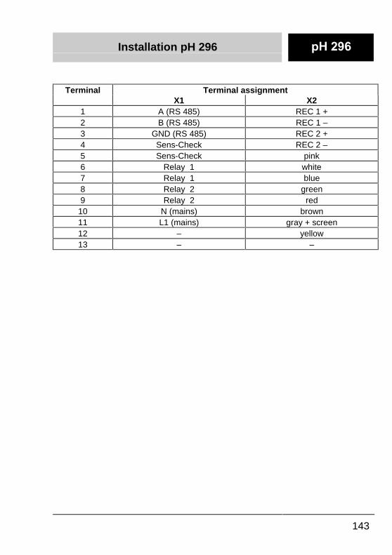
Terminal Terminal assignmentX1 X2
1 A (RS 485) REC 1 +2 B (RS 485) REC 1 –3 GND (RS 485) REC 2 +4 Sens-Check REC 2 –5 Sens-Check pink6 Relay 1 white7 Relay 1 blue8 Relay 2 green9 Relay 2 red
10 N (mains) brown11 L1 (mains) gray + screen12 – yellow13 – –
Installation pH 296
144
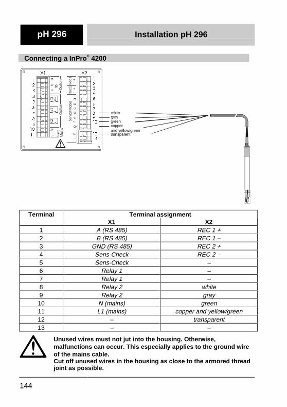
Connecting a InPro® 4200
Terminal Terminal assignmentX1 X2
1 A (RS 485) REC 1 +2 B (RS 485) REC 1 –3 GND (RS 485) REC 2 +4 Sens-Check REC 2 –5 Sens-Check –6 Relay 1 –7 Relay 1 –8 Relay 2 white9 Relay 2 gray
10 N (mains) green11 L1 (mains) copper and yellow/green12 – transparent13 – –
Unused wires must not jut into the housing. Otherwise,malfunctions can occur. This especially applies to the ground wireof the mains cable.Cut off unused wires in the housing as close to the armored threadjoint as possible.
�
��
�
��
�
�
�
�
�
�
�� �
�
�
�
�
�
��
�
��
�
��
��
;�;�
Installation pH 296
145
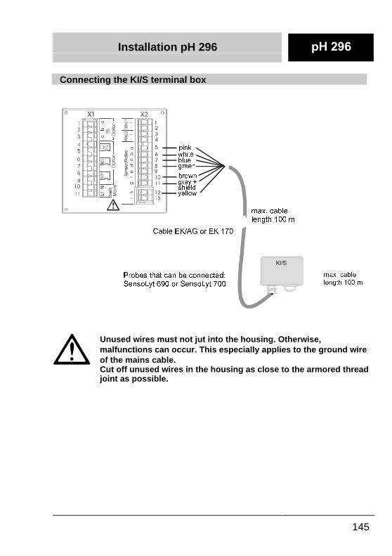
Connecting the KI/S terminal box
�
Unused wires must not jut into the housing. Otherwise,malfunctions can occur. This especially applies to the ground wireof the mains cable.�Cut off unused wires in the housing as close to the armored threadjoint as possible.
SLQN
PD[��FDEOHOHQJWK�����P
&DEOH�(.�$*�RU�(.����
3UREHV�WKDW�FDQ�EH�FRQQHFWHG�6HQVR/\W�����RU�6HQVR/\W����
PD[��FDEOHOHQJWK�����P
ZKLWHEOXHJUHHQ
EURZQJUD\��VKLHOG\HOORZ
Installation pH 296
146
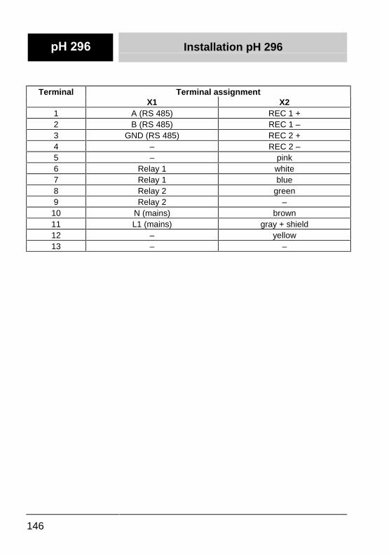
Terminal Terminal assignmentX1 X2
1 A (RS 485) REC 1 +2 B (RS 485) REC 1 –3 GND (RS 485) REC 2 +4 – REC 2 –5 – pink6 Relay 1 white7 Relay 1 blue8 Relay 2 green9 Relay 2 –
10 N (mains) brown11 L1 (mains) gray + shield12 – yellow13 – –
Installation pH 296
147
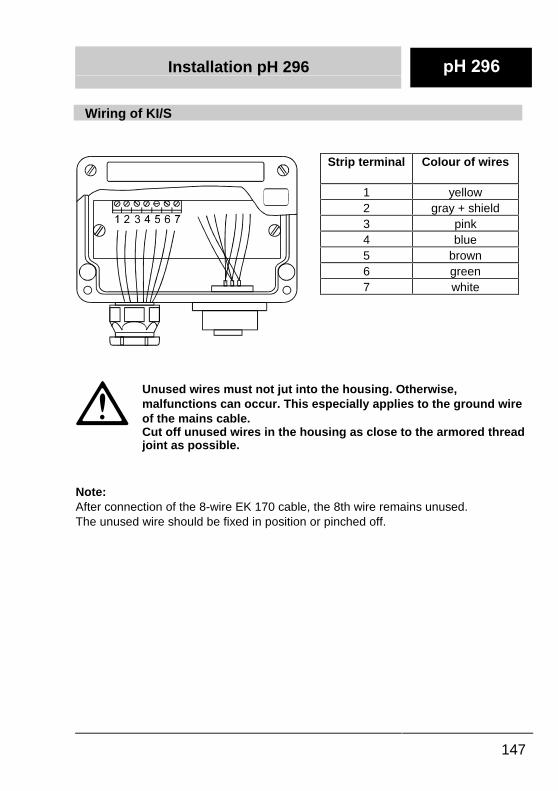
�Wiring of KI/S�
�
���
�
Unused wires must not jut into the housing. Otherwise,malfunctions can occur. This especially applies to the ground wireof the mains cable.�Cut off unused wires in the housing as close to the armored threadjoint as possible.
��Note:After connection of the 8-wire EK 170 cable, the 8th wire remains unused.�The unused wire should be fixed in position or pinched off.�
�Strip terminal �Colour of wires�
�1 �yellow�2 �gray + shield�3 �pink�4 �blue�5 �brown�6 �green�7 �white
�
S+ ����S+ ���
Configuration
148
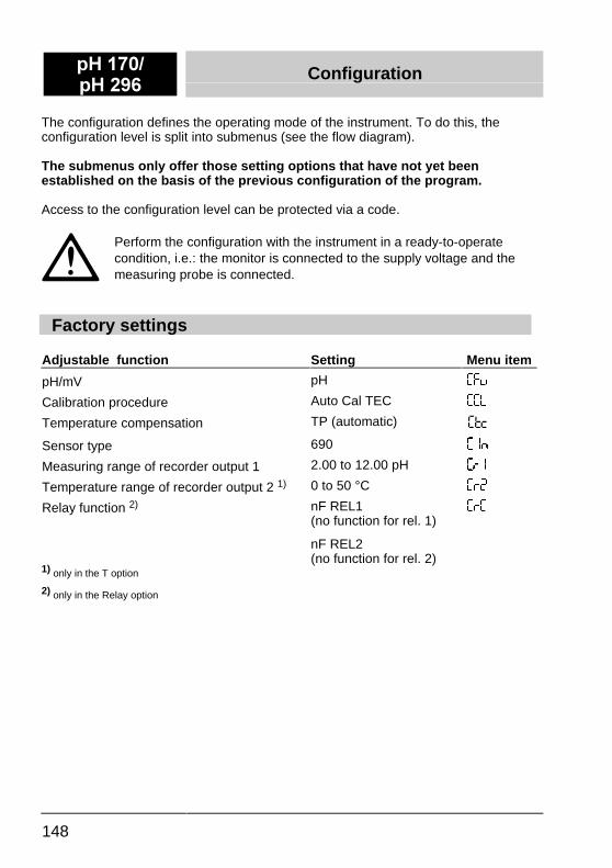
The configuration defines the operating mode of the instrument. To do this, theconfiguration level is split into submenus (see the flow diagram).
The submenus only offer those setting options that have not yet beenestablished on the basis of the previous configuration of the program.
Access to the configuration level can be protected via a code.
Perform the configuration with the instrument in a ready-to-operatecondition, i.e.: the monitor is connected to the supply voltage and themeasuring probe is connected.
Factory settings
Adjustable function Setting Menu item
pH/mV pH ��+
Calibration procedure Auto Cal TEC ��/
Temperature compensation TP (automatic)
Sensor type 690 ��
Measuring range of recorder output 1 2.00 to 12.00 pH ���
Temperature range of recorder output 2 1) 0 to 50 °C ���
Relay function 2) nF REL1(no function for rel. 1)
nF REL2(no function for rel. 2)
���
1) only in the T option
2) only in the Relay option
Configuration S+ ����S+ ���
149
Calling up the configuration level
-� Press the DOWN key.
-� Press the ENTER key.
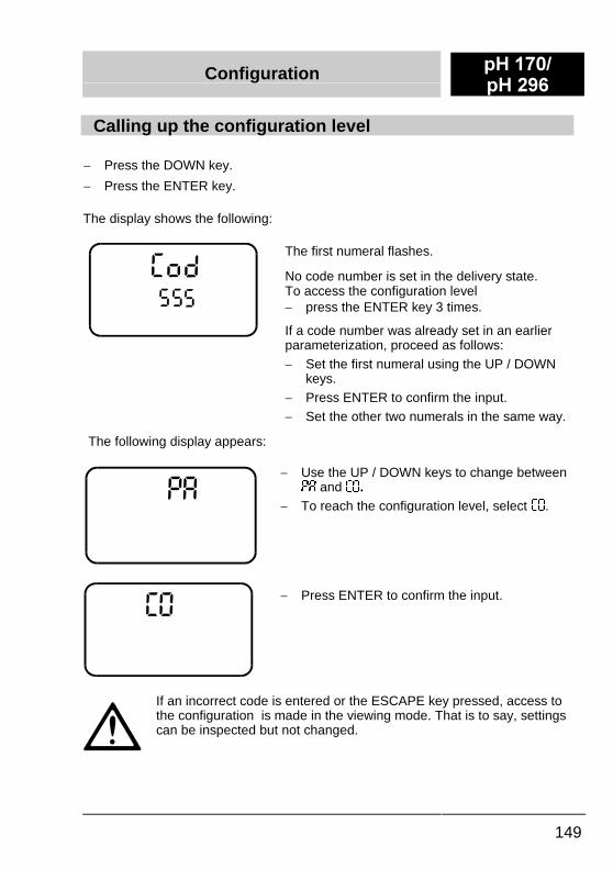
The display shows the following:
The first numeral flashes.
No code number is set in the delivery state.To access the configuration level-� press the ENTER key 3 times.
If a code number was already set in an earlierparameterization, proceed as follows:-� Set the first numeral using the UP / DOWN
keys.-� Press ENTER to confirm the input.-� Set the other two numerals in the same way.
The following display appears:
-�-� Use the UP / DOWN keys to change between
-� and ��.-� To reach the configuration level, select ��.
-� Press ENTER to confirm the input.
If an incorrect code is entered or the ESCAPE key pressed, access tothe configuration is made in the viewing mode. That is to say, settingscan be inspected but not changed.
S+ ����S+ ���
Configuration
150
Overview table of the submenus
Display Description Option
Basicinstrument
Relay T option
��6 Select the measuring mode +
��/ Select the calibrating procedure +
Select the temperature compensation +
�� Select the sensor type +
��� Select recorder 1 +
��� Select recorder 2 +
��� Assignment of the pilot relay +
��� Operating mode of the pilot relay +
+ Menu appears in the corresponding model of the instrument.
Selecting the measuring mode
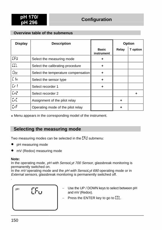
Two measuring modes can be selected in the ��6 submenu:
�� pH measuring mode
�� mV (Redox) measuring mode
Note:In the operating mode, pH with SensoLyt 700 Sensor, glassbreak monitoring ispermanently switched on.In the mV operating mode and the pH with SensoLyt 690 operating mode or inExternal sensors, glassbreak monitoring is permanently switched off..
��+pH -� Use the UP / DOWN keys to select between pH
and mV (Redox).
-� Press the ENTER key to go to ��/.
Configuration S+ ����S+ ���
151
Selecting the calibrating procedure
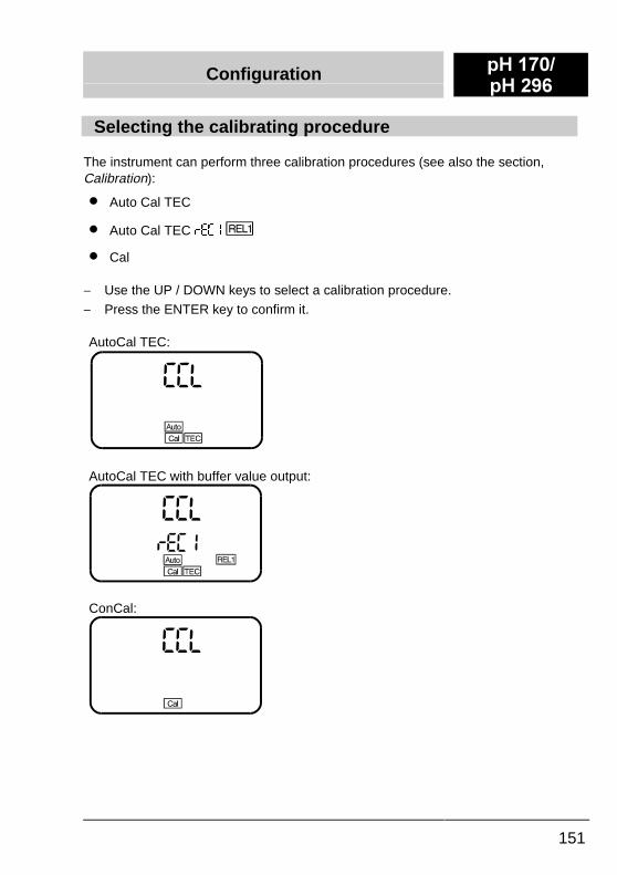
The instrument can perform three calibration procedures (see also the section,Calibration):
�� Auto Cal TEC
�� Auto Cal TEC )���
�� Cal
-� Use the UP / DOWN keys to select a calibration procedure.
-� Press the ENTER key to confirm it.
AutoCal TEC:
AutoCal TEC with buffer value output:
ConCal:
S+ ����S+ ���
Configuration
152
Selecting the temperature compensation
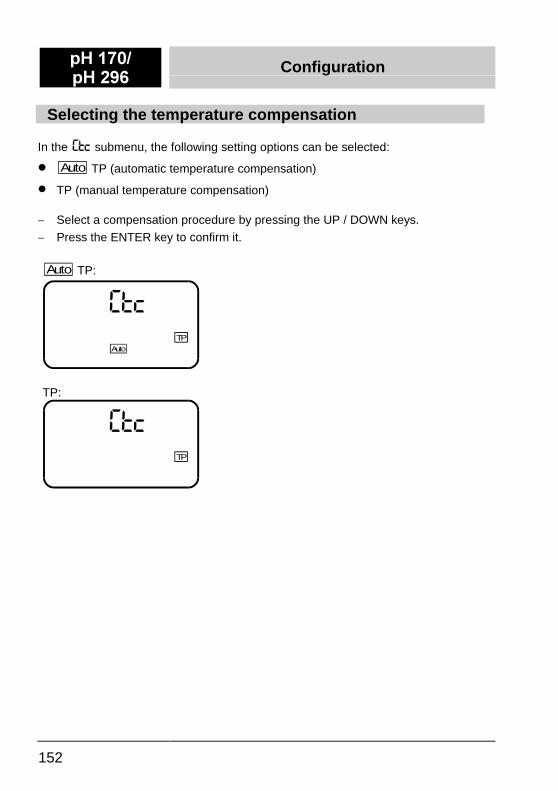
In the submenu, the following setting options can be selected:
�� Auto TP (automatic temperature compensation)
�� TP (manual temperature compensation)
-� Select a compensation procedure by pressing the UP / DOWN keys.
-� Press the ENTER key to confirm it.
Auto TP:
�*8TP
Auto
TP:
�*8TP
Configuration S+ ����S+ ���
153
Selecting the sensor
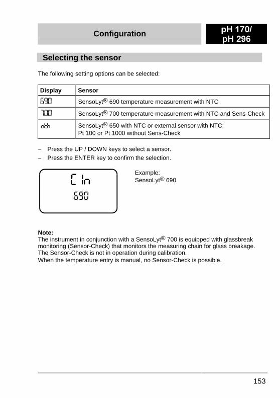
The following setting options can be selected:
Display Sensor
��� SensoLyt® 690 temperature measurement with NTC
��� SensoLyt® 700 temperature measurement with NTC and Sens-Check
SensoLyt® 650 with NTC or external sensor with NTC;Pt 100 or Pt 1000 without Sens-Check
-� Press the UP / DOWN keys to select a sensor.
-� Press the ENTER key to confirm the selection.
�'���
Example:SensoLyt® 690
Note:The instrument in conjunction with a SensoLyt® 700 is equipped with glassbreakmonitoring (Sensor-Check) that monitors the measuring chain for glass breakage.The Sensor-Check is not in operation during calibration.When the temperature entry is manual, no Sensor-Check is possible.
S+ ����S+ ���
Configuration
154
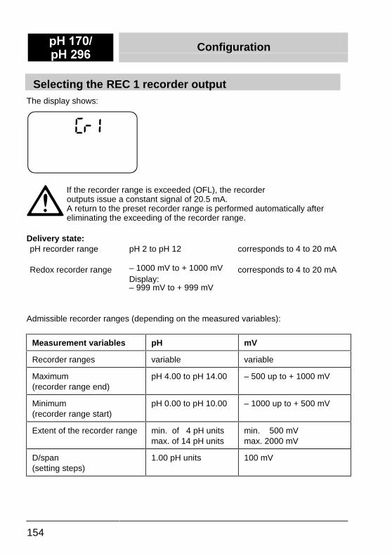
Selecting the REC 1 recorder outputThe display shows:
If the recorder range is exceeded (OFL), the recorderoutputs issue a constant signal of 20.5 mA.A return to the preset recorder range is performed automatically aftereliminating the exceeding of the recorder range.
Delivery state:pH recorder range pH 2 to pH 12 corresponds to 4 to 20 mA
Redox recorder range – 1000 mV to + 1000 mVDisplay:– 999 mV to + 999 mV
corresponds to 4 to 20 mA
Admissible recorder ranges (depending on the measured variables):
Measurement variables pH mV
Recorder ranges variable variable
Maximum(recorder range end)
pH 4.00 to pH 14.00 – 500 up to + 1000 mV
Minimum(recorder range start)
pH 0.00 to pH 10.00 – 1000 up to + 500 mV
Extent of the recorder range min. of 4 pH unitsmax. of 14 pH units
min. 500 mVmax. 2000 mV
D/span(setting steps)
1.00 pH units 100 mV
Configuration S+ ����S+ ���
155
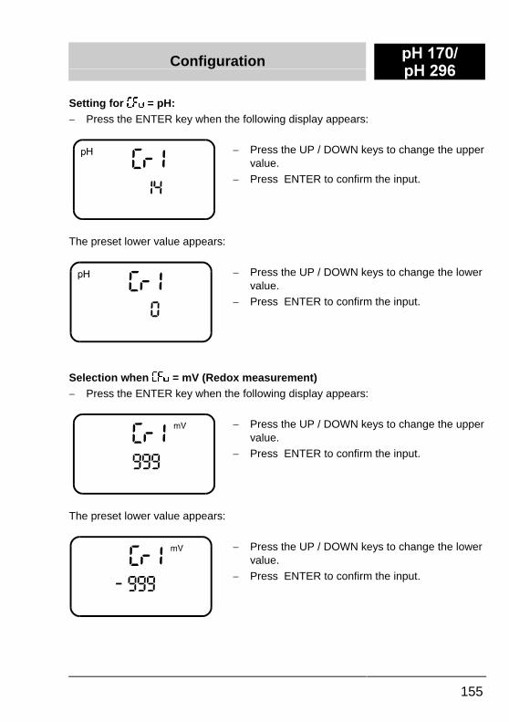
Setting for ��+ = pH:-� Press the ENTER key when the following display appears:
-� Press the UP / DOWN keys to change the uppervalue.
-� Press ENTER to confirm the input.
The preset lower value appears:
-� Press the UP / DOWN keys to change the lowervalue.
-� Press ENTER to confirm the input.
Selection when ��+ = mV (Redox measurement)-� Press the ENTER key when the following display appears:
-� Press the UP / DOWN keys to change the uppervalue.
-� Press ENTER to confirm the input.
The preset lower value appears:
-� Press the UP / DOWN keys to change the lowervalue.
-� Press ENTER to confirm the input.
S+ ����S+ ���
Configuration
156
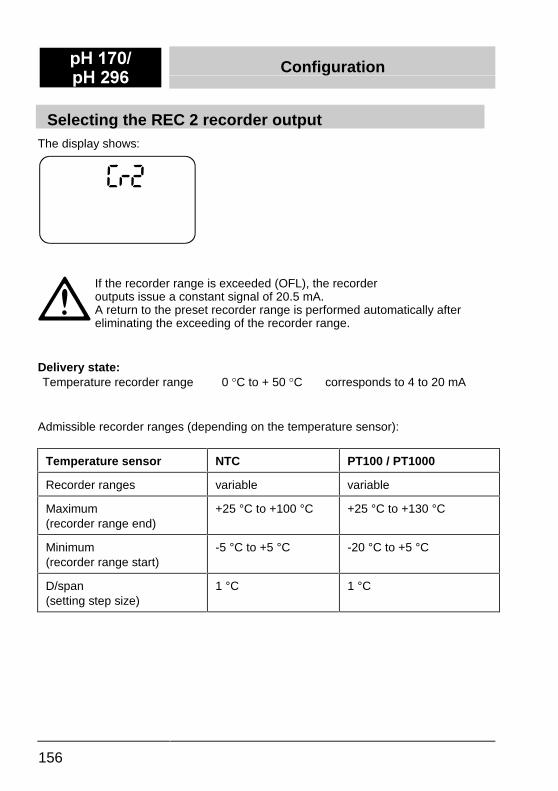
Selecting the REC 2 recorder outputThe display shows:
If the recorder range is exceeded (OFL), the recorderoutputs issue a constant signal of 20.5 mA.A return to the preset recorder range is performed automatically aftereliminating the exceeding of the recorder range.
Delivery state:Temperature recorder range 0 �C to + 50 �C corresponds to 4 to 20 mA
Admissible recorder ranges (depending on the temperature sensor):
Temperature sensor NTC PT100 / PT1000
Recorder ranges variable variable
Maximum(recorder range end)
+25 °C to +100 °C +25 °C to +130 °C
Minimum(recorder range start)
-5 °C to +5 °C -20 °C to +5 °C
D/span(setting step size)
1 °C 1 °C
Configuration S+ ����S+ ���
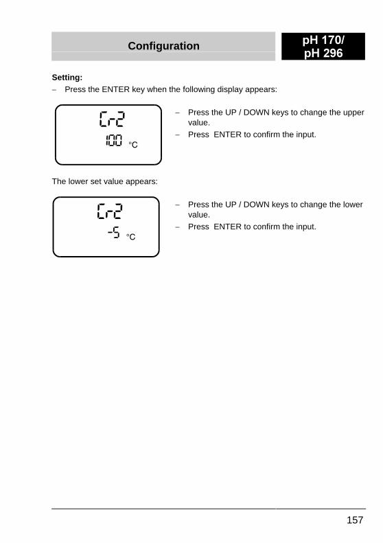
157
Setting:-� Press the ENTER key when the following display appears:
-� Press the UP / DOWN keys to change the uppervalue.
-� Press ENTER to confirm the input.
The lower set value appears:
-� Press the UP / DOWN keys to change the lowervalue.
-� Press ENTER to confirm the input.
S+ ����S+ ���
Configuration
158
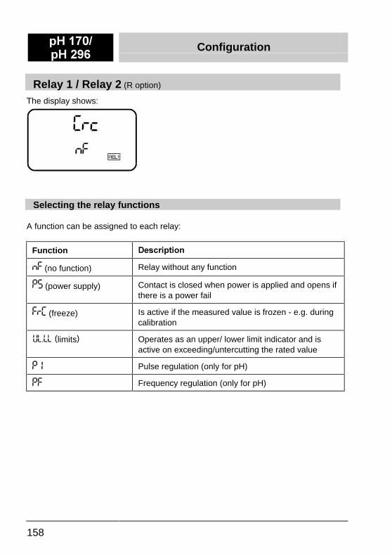
Relay 1 / Relay 2 (R option)
The display shows:
Selecting the relay functions
A function can be assigned to each relay:
Function 'HVFULSWLRQ
'� (no function) Relay without any function
-� (power supply) Contact is closed when power is applied and opens ifthere is a power fail
�)� (freeze) Is active if the measured value is frozen - e.g. duringcalibration
(limits) Operates as an upper/ lower limit indicator and isactive on exceeding/untercutting the rated value
- Pulse regulation (only for pH)
-� Frequency regulation (only for pH)
Configuration S+ ����S+ ���
159
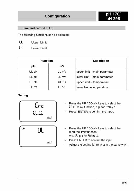
Limit indicator (UL.LL)
7KH�IROORZLQJ�IXQFWLRQV�FDQ�EH�VHOHFWHG�
6/ Upper Limit
// Lower Limit
)XQFWLRQ 'HVFULSWLRQ
S+ P9
8/�S+ 8/�P9 XSSHU�OLPLW�±�PDLQ�SDUDPHWHU
//�S+ //�P9 ORZHU�OLPLW�±�PDLQ�SDUDPHWHU
8/��& 8/��& XSSHU�OLPLW�±�WHPSHUDWXUH
//��& //��& ORZHU�OLPLW�±�WHPSHUDWXUH
Setting:
�)86/ //
REL1
-� Press the UP / DOWN keys to select the.//�
relay function, e.g. for Relay 1.
-� Press ENTER to confirm the input.
6/pH
REL1
-� Press the UP / DOWN keys to select therequired limit function,e.g. pH for Relay 1.
-� Press ENTER to confirm the input.
-� Adjust the setting for relay 2 in the same way.

S+ ����S+ ���
Configuration
160
Pulse regulator (PI)
In impulse regulation, the output relay -within a preselected proportional band -is clocked and the switch contact isclosed for a longer or shorter timeaccording to the deviation from the limit.
�� In larger deviations of the measuredvalue from the limit, the contact isclosed longer and the pause is short.
�� If the value is close to the limit, thecontact is closed only briefly and thepause is correspondingly longer.
The total time (switch-on and switch-offtime) is designated as the switchingperiod, T.While the switching times varydepending on the control deviation, thetime intervall, T, remains constant (seeadjacent figure).Pulse duration regulators are used for,e.g. the control of valves.Within the set up proportional band, Xp,the relative duration of operation of therelay lies between 10 and 90%.
Setting parameter:
Setting range T: 5 to 100 sec. (interval)Proportional band, Xp: Set in steps of 0.1 pH over the whole measuring range.Basic setting: 10 sec, proportional band of 1 pH
5HOD\
21
2))
7LPH>V@
W2))
W21
T
5HODWLYH�VZLWFKLQJ�GXUDWLRQ �W ������������������������������������������������������7
21�
Configuration S+ ����S+ ���
161
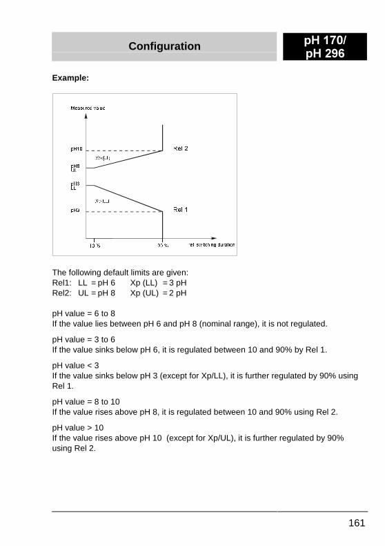
Example:
The following default limits are given:Rel1: LL = pH 6 Xp (LL) = 3 pHRel2: UL = pH 8 Xp (UL) = 2 pH
pH value = 6 to 8If the value lies between pH 6 and pH 8 (nominal range), it is not regulated.
pH value = 3 to 6If the value sinks below pH 6, it is regulated between 10 and 90% by Rel 1.
pH value < 3If the value sinks below pH 3 (except for Xp/LL), it is further regulated by 90% usingRel 1.
pH value = 8 to 10If the value rises above pH 8, it is regulated between 10 and 90% using Rel 2.
pH value > 10If the value rises above pH 10 (except for Xp/UL), it is further regulated by 90%using Rel 2.
S+�
S+�//
S+�8/
S+��
�������� ����
0HDVXUHG�YDOXH
UHO��VZLWFKLQJ�GXUDWLRQ
5HO��
5HO��
;S��8/�
;S��//�
S+ ����S+ ���
Configuration
162
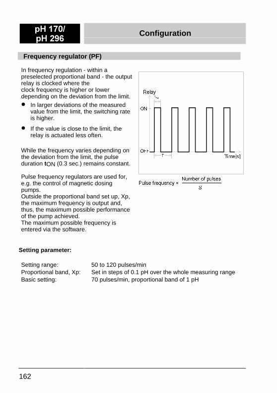
Frequency regulator (PF)
In frequency regulation - within apreselected proportional band - the outputrelay is clocked where theclock frequency is higher or lowerdepending on the deviation from the limit.�� In larger deviations of the measured
value from the limit, the switching rateis higher.
�� If the value is close to the limit, therelay is actuated less often.
While the frequency varies depending onthe deviation from the limit, the pulseduration tON (0.3 sec.) remains constant.
Pulse frequency regulators are used for,e.g. the control of magnetic dosingpumps.Outside the proportional band set up, Xp,the maximum frequency is output and,thus, the maximum possible performanceof the pump achieved.The maximum possible frequency isentered via the software.
Setting parameter:
Setting range: 50 to 120 pulses/minProportional band, Xp: Set in steps of 0.1 pH over the whole measuring rangeBasic setting: 70 pulses/min, proportional band of 1 pH
5HOD\
21
2))
7LPH>V@
W21
7
3XOVH�IUHTXHQF\� ��1XPEHU�RI�SXOVHV
6
Configuration S+ ����S+ ���
163
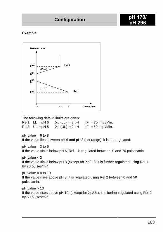
Example:
The following default limits are given:Rel1: LL = pH 6 Xp (LL) = 3 pH tF = 70 Imp./Min.Rel2: UL = pH 8 Xp (UL) = 2 pH tF = 50 Imp./Min.
pH value = 6 to 8If the value lies between pH 6 and pH 8 (set range), it is not regulated.
pH value = 3 to 6If the value sinks below pH 6, Rel 1 is regulated between 0 and 70 pulses/min
pH value < 3If the value sinks below pH 3 (except for Xp/LL), it is further regulated using Rel 1by 70 pulses/min.
pH value = 8 to 10If the value rises above pH 8, it is regulated using Rel 2 between 0 and 50pulses/min.
pH value > 10If the value rises above pH 10 (except for Xp/UL), it is further regulated using Rel 2by 50 pulses/min.
S+�
S+�//
;S��//�
S+�8/
S+��
� ��
0HDVXUHG�YDOXH
W �>SXOVHV��PLQ�@)
5HO��
5HO��
;S��8/�
��
S+ ����S+ ���
Configuration
164
Proportional band, Xp
The proportional band Xp lies above or below the limiting value.When entering a PL UL (Upper Limit) limiting value, Xp begins above therespective limit whereas , when entering a PL LL (Lower Limit) limiting value, itbegins below the respective limit.
Thus, this results in a limit range for PL UL of:
�� pH 0.0 to pH 13.9 (0.1 pH minimum proportional band)
and for PL LL, a limit of:
�� pH 0.1 to pH 14 (0.1 pH minimum proportional band).
Note:Thus, the Xp proportional band can have a minimum value of 0.1 pH and amaximum value of 13.9 pH.
Configuration S+ ����S+ ���
165
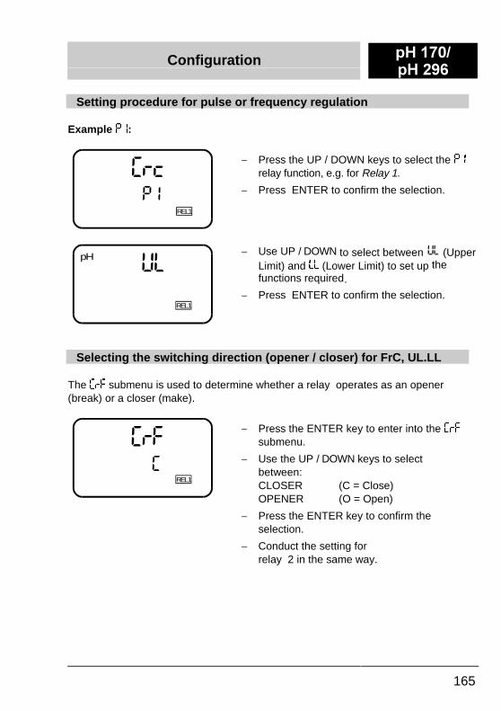
Setting procedure for pulse or frequency regulation
Example -:
�)8
REL1
-
-� Press the UP / DOWN keys to select the -relay function, e.g. for Relay 1.
-� Press ENTER to confirm the selection.
6/
REL1
pH -� Use UP / DOWN to select between (UpperLimit) and // (Lower Limit) to set up thefunctions required.
-� Press ENTER to confirm the selection.
Selecting the switching direction (opener / closer) for FrC, UL.LL
The �)� submenu is used to determine whether a relay operates as an opener(break) or a closer (make).
REL1
�)��
-� Press the ENTER key to enter into the �)�submenu.
-� Use the UP / DOWN keys to selectbetween:CLOSER (C = Close)OPENER (O = Open)
-� Press the ENTER key to confirm theselection.
-� Conduct the setting forrelay 2 in the same way.
S+ ����S+ ���
Parameterization
166
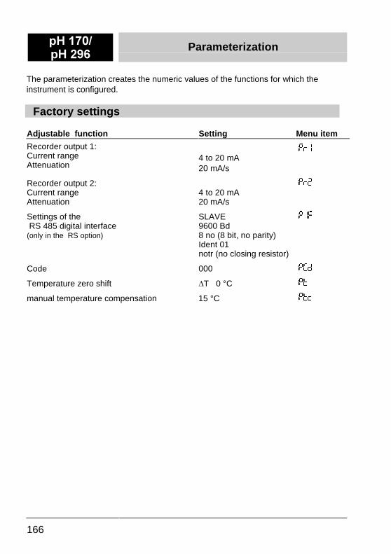
The parameterization creates the numeric values of the functions for which theinstrument is configured.
Factory settings
Adjustable function Setting Menu item
Recorder output 1:Current rangeAttenuation
4 to 20 mA20 mA/s
-��
Recorder output 2:Current rangeAttenuation
4 to 20 mA20 mA/s
-��
Settings of the RS 485 digital interface(only in the RS option)
SLAVE9600 Bd8 no (8 bit, no parity)Ident 01notr (no closing resistor)
-��
Code 000 -��
Temperature zero shift DT 0 °C -*
manual temperature compensation 15 °C -*8
Parameterization S+ ����S+ ���
167
Calling up the parameterization level
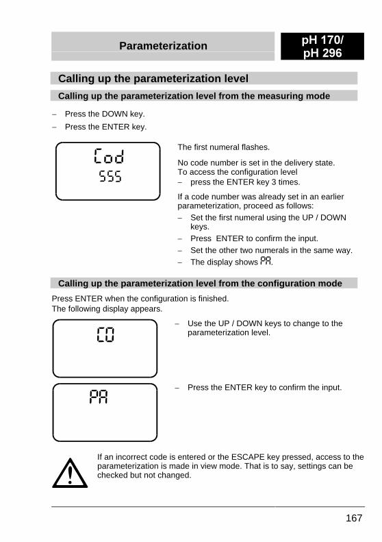
Calling up the parameterization level from the measuring mode
-� Press the DOWN key.
-� Press the ENTER key.
The first numeral flashes.
No code number is set in the delivery state.To access the configuration level-� press the ENTER key 3 times.
If a code number was already set in an earlierparameterization, proceed as follows:-� Set the first numeral using the UP / DOWN
keys.-� Press ENTER to confirm the input.-� Set the other two numerals in the same way.-� The display shows -�.
Calling up the parameterization level from the configuration mode
Press ENTER when the configuration is finished.The following display appears.
-� Use the UP / DOWN keys to change to theparameterization level.
-� Press the ENTER key to confirm the input.
If an incorrect code is entered or the ESCAPE key pressed, access to theparameterization is made in view mode. That is to say, settings can bechecked but not changed.
S+ ����S+ ���
Parameterization
168
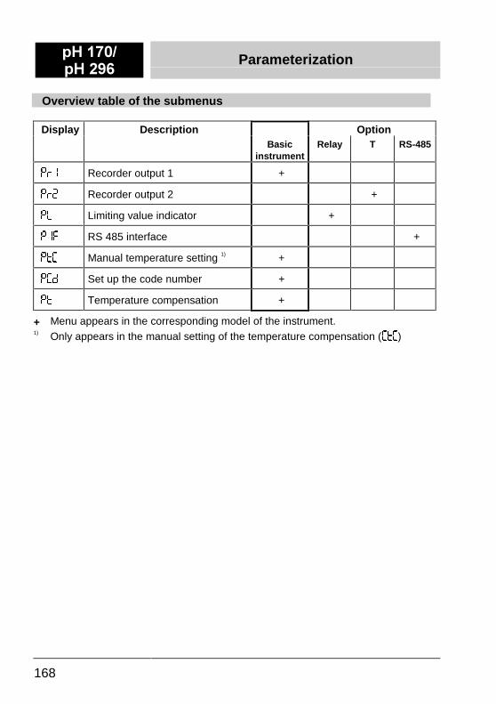
Overview table of the submenus
Display Description OptionBasic
instrumentRelay T RS-485
-)� Recorder output 1 +
-)� Recorder output 2 +
-/ Limiting value indicator +
-� RS 485 interface +
-*� Manual temperature setting 1) +
-�& Set up the code number +
-* Temperature compensation +
+ Menu appears in the corresponding model of the instrument.1) Only appears in the manual setting of the temperature compensation (�*�)
Parameterization S+ ����S+ ���
169
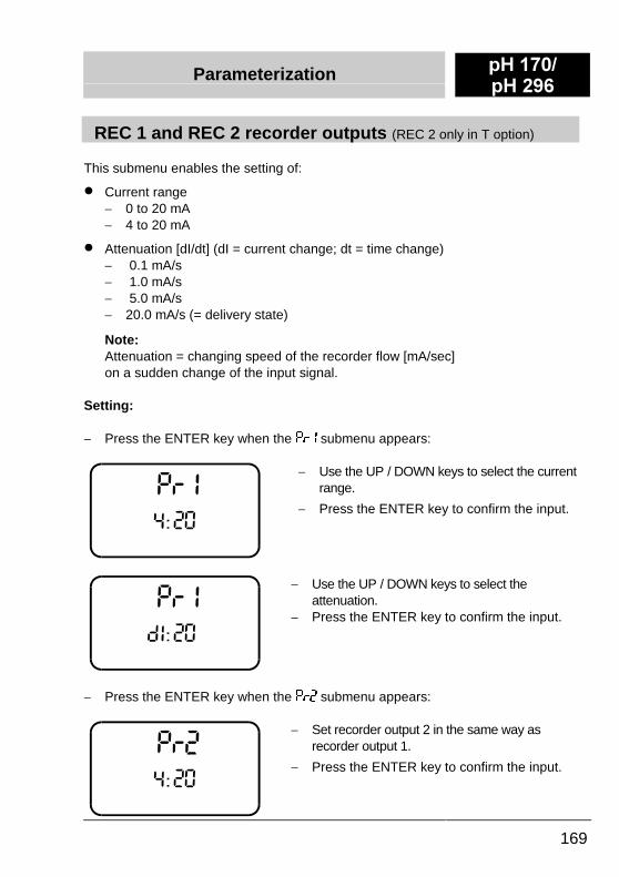
REC 1 and REC 2 recorder outputs (REC 2 only in T option)
This submenu enables the setting of:
�� Current range-� 0 to 20 mA-� 4 to 20 mA
�� Attenuation [dI/dt] (dI = current change; dt = time change)-� 0.1 mA/s-� 1.0 mA/s-� 5.0 mA/s-� 20.0 mA/s (= delivery state)
Note:Attenuation = changing speed of the recorder flow [mA/sec]on a sudden change of the input signal.
Setting:
-� Press the ENTER key when the -)��submenu appears:
-� Use the UP / DOWN keys to select the currentrange.
-� Press the ENTER key to confirm the input.
-� Use the UP / DOWN keys to select theattenuation.
-� Press the ENTER key to confirm the input.
-� Press the ENTER key when the -)� submenu appears:
-� Set recorder output 2 in the same way asrecorder output 1.
-� Press the ENTER key to confirm the input.
S+ ����S+ ���
Parameterization
170
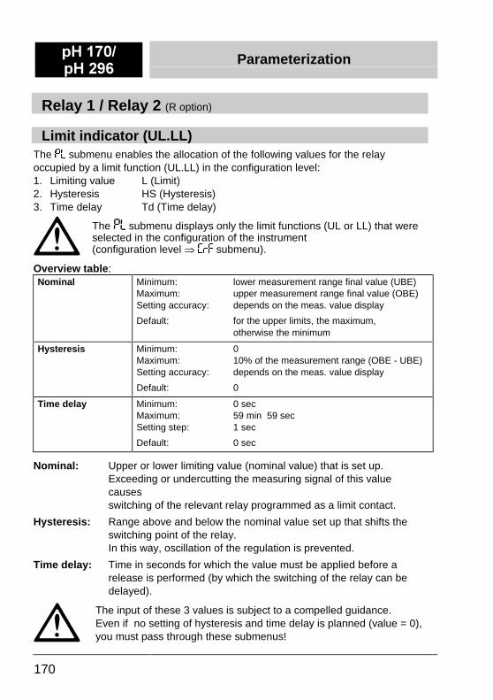
Relay 1 / Relay 2 (R option)
Limit indicator (UL.LL)The -/ submenu enables the allocation of the following values for the relayoccupied by a limit function (UL.LL) in the configuration level:1.� Limiting value L (Limit)2.� Hysteresis HS (Hysteresis)3.� Time delay Td (Time delay)
The -/ submenu displays only the limit functions (UL or LL) that wereselected in the configuration of the instrument(configuration level à �)� submenu).
Overview table:Nominal Minimum: lower measurement range final value (UBE)
Maximum: upper measurement range final value (OBE)Setting accuracy: depends on the meas. value display
Default: for the upper limits, the maximum,otherwise the minimum
Hysteresis Minimum: 0Maximum: 10% of the measurement range (OBE - UBE)Setting accuracy: depends on the meas. value display
Default: 0
Time delay Minimum: 0 secMaximum: 59 min 59 secSetting step: 1 sec
Default: 0 sec
Nominal: Upper or lower limiting value (nominal value) that is set up.Exceeding or undercutting the measuring signal of this value causesswitching of the relevant relay programmed as a limit contact.
Hysteresis: Range above and below the nominal value set up that shifts the switching point of the relay.In this way, oscillation of the regulation is prevented.
Time delay: Time in seconds for which the value must be applied before a release is performed (by which the switching of the relay can be delayed).
The input of these 3 values is subject to a compelled guidance.Even if no setting of hysteresis and time delay is planned (value = 0),you must pass through these submenus!
Parameterization S+ ����S+ ���
171
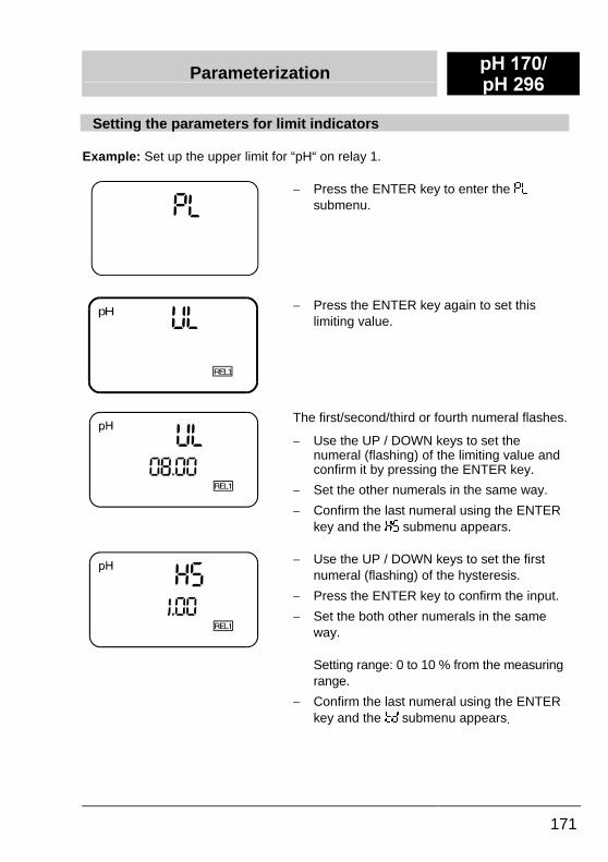
Setting the parameters for limit indicators
Example: Set up the upper limit for “pH“ on relay 1.
-� Press the ENTER key to enter the -/submenu.
6/pH
REL1
-� Press the ENTER key again to set thislimiting value.
The first/second/third or fourth numeral flashes.
-� Use the UP / DOWN keys to set thenumeral (flashing) of the limiting value andconfirm it by pressing the ENTER key.
-� Set the other numerals in the same way.
-� Confirm the last numeral using the ENTERkey and the �� submenu appears.
-� Use the UP / DOWN keys to set the firstnumeral (flashing) of the hysteresis.
-� Press the ENTER key to confirm the input.
-� Set the both other numerals in the sameway.
Setting range: 0 to 10 % from the measuringrange.
-� Confirm the last numeral using the ENTERkey and the *& submenu appears.
S+ ����S+ ���
Parameterization
172
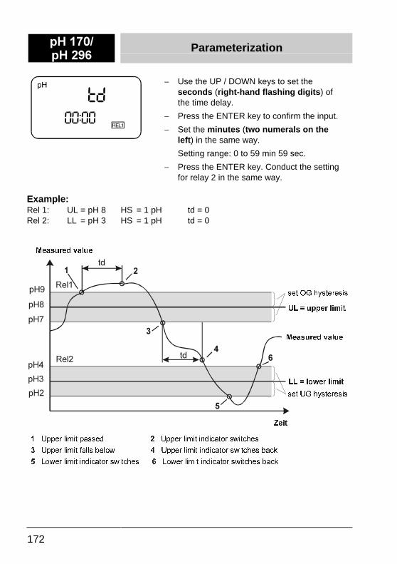
-� Use the UP / DOWN keys to set theseconds (right-hand flashing digits) ofthe time delay.
-� Press the ENTER key to confirm the input.
-� Set the minutes (two numerals on theleft) in the same way.
Setting range: 0 to 59 min 59 sec.
-� Press the ENTER key. Conduct the settingfor relay 2 in the same way.
Example:Rel 1: UL = pH 8 HS = 1 pH td = 0Rel 2: LL = pH 3 HS = 1 pH td = 0
���� �����������������������
���� �������������������
� �
8SSHU�OLPLW�SDVVHG��� 8SSHU�OLPLW�LQGLFDWRU�VZLWFKHV
8SSHU�OLPLW�IDOOV�EHORZ�� 8SSHU�OLPLW�LQGLFDWRU�VZLWFKHV�EDFN
���/RZHU�OLPLW�LQGLFDWRU�VZLWFKHV������ ���/RZHU�OLPLW�LQGLFDWRU�VZLWFKHV�EDFN
VHW�2*�K\VWHUHVLV
VHW�8*�K\VWHUHVLV
0HDVXUHG�YDOXH
0HDVXUHG�YDOXH
��8/� �XSSHU�OLPLW
//� �ORZHU�OLPLW
=HLW
� �
�
�
�
�
S+�
S+�
S+�
S+�
S+�
S+�
5HO�
WG
WG5HO�
Parameterization S+ ����S+ ���
173
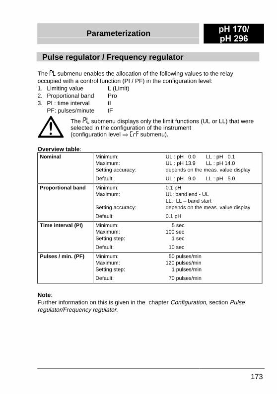
Pulse regulator / Frequency regulator
The -/ submenu enables the allocation of the following values to the relayoccupied with a control function (PI / PF) in the configuration level:1.� Limiting value L (Limit)2.� Proportional band Pro3.� PI : time interval tI
PF: pulses/minute tF
The -/ submenu displays only the limit functions (UL or LL) that wereselected in the configuration of the instrument(configuration level à �)��
submenu).
Overview table:Nominal Minimum: UL : pH 0.0 LL : pH 0.1
Maximum: UL : pH 13.9 LL : pH 14.0Setting accuracy: depends on the meas. value display
Default: UL : pH 9.0 LL : pH 5.0
Proportional band Minimum: 0.1 pHMaximum: UL: band end - UL
LL: LL – band startSetting accuracy: depends on the meas. value display
Default: 0.1 pH
Time interval (PI) Minimum: 5 secMaximum: 100 secSetting step: 1 sec
Default: 10 sec
Pulses / min. (PF) Minimum: 50 pulses/minMaximum: 120 pulses/minSetting step: 1 pulses/min
Default: 70 pulses/min
Note:Further information on this is given in the chapter Configuration, section Pulseregulator/Frequency regulator.
S+ ����S+ ���
Parameterization
174
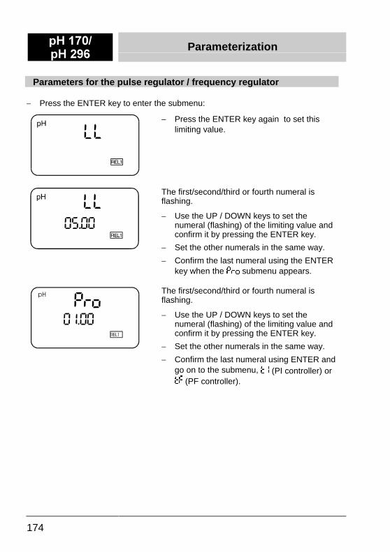
Parameters for the pulse regulator / frequency regulator
-� Press the ENTER key to enter the submenu:
-� Press the ENTER key again to set thislimiting value.
The first/second/third or fourth numeral isflashing.
-� Use the UP / DOWN keys to set thenumeral (flashing) of the limiting value andconfirm it by pressing the ENTER key.
-� Set the other numerals in the same way.
-� Confirm the last numeral using the ENTERkey when the -)(�
submenu appears.
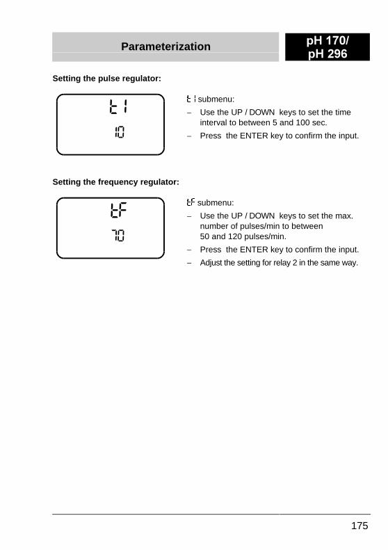
The first/second/third or fourth numeral isflashing.
-� Use the UP / DOWN keys to set thenumeral (flashing) of the limiting value andconfirm it by pressing the ENTER key.
-� Set the other numerals in the same way.
-� Confirm the last numeral using ENTER andgo on to the submenu, * (PI controller) or*� (PF controller).
Parameterization S+ ����S+ ���
175
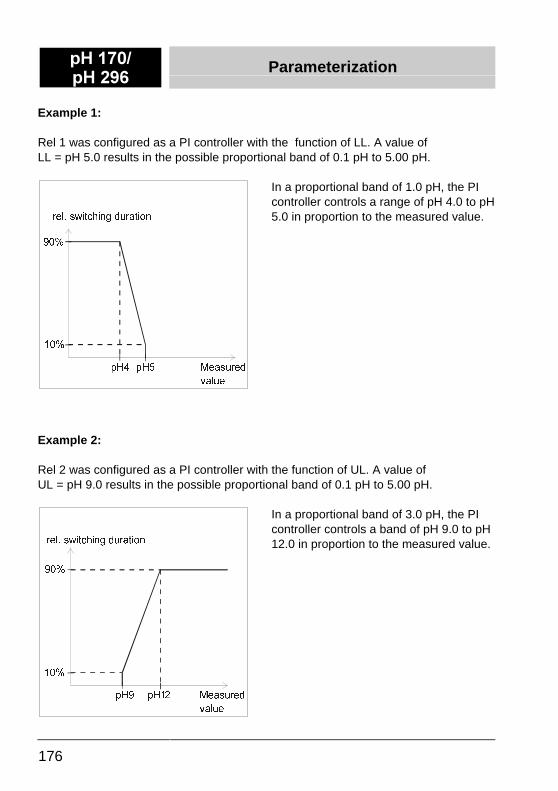
Setting the pulse regulator:
��
**�
submenu:
-� Use the UP / DOWN keys to set the timeinterval to between 5 and 100 sec.
-� Press the ENTER key to confirm the input.
Setting the frequency regulator:
��
*�*��
submenu:
-� Use the UP / DOWN keys to set the max.number of pulses/min to between50 and 120 pulses/min.
-� Press the ENTER key to confirm the input.
-� Adjust the setting for relay 2 in the same way.
S+ ����S+ ���
Parameterization
176
Example 1:
Rel 1 was configured as a PI controller with the function of LL. A value ofLL = pH 5.0 results in the possible proportional band of 0.1 pH to 5.00 pH.
In a proportional band of 1.0 pH, the PIcontroller controls a range of pH 4.0 to pH5.0 in proportion to the measured value.
Example 2:
Rel 2 was configured as a PI controller with the function of UL. A value ofUL = pH 9.0 results in the possible proportional band of 0.1 pH to 5.00 pH.
In a proportional band of 3.0 pH, the PIcontroller controls a band of pH 9.0 to pH12.0 in proportion to the measured value.
���
S+� S+�
���
UHO��VZLWFKLQJ�GXUDWLRQ
0HDVXUHG�
YDOXH
���
S+� S+��
���
0HDVXUHG�
YDOXH
UHO��VZLWFKLQJ�GXUDWLRQ
Parameterization S+ ����S+ ���
177
RS 485 interface (RS option)
�� Call up the -� submenu using ENTER:
The parameterization of the RS 485 interface is described in a separate manualthat is included within the scope of delivery of instruments with a RS 485 interface(RS instrument version).
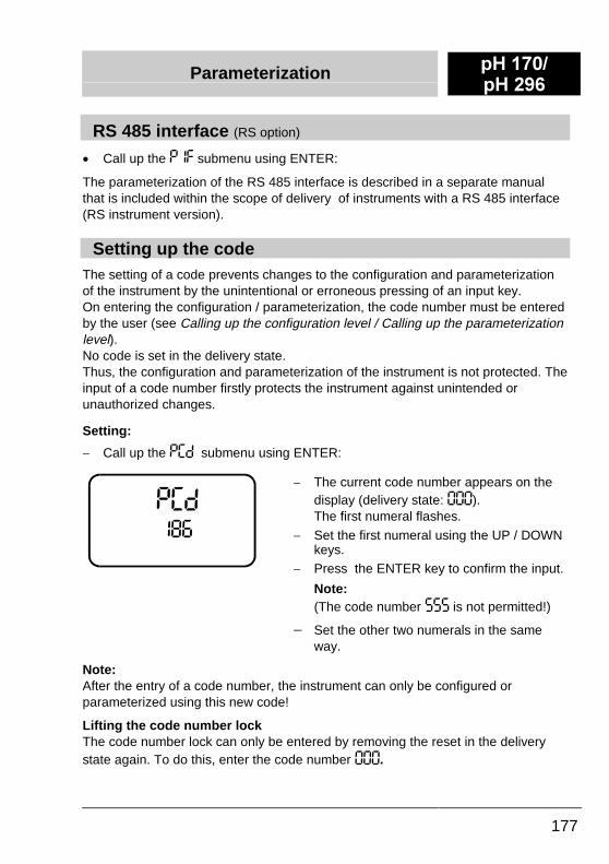
Setting up the codeThe setting of a code prevents changes to the configuration and parameterizationof the instrument by the unintentional or erroneous pressing of an input key.On entering the configuration / parameterization, the code number must be enteredby the user (see Calling up the configuration level / Calling up the parameterizationlevel).No code is set in the delivery state.Thus, the configuration and parameterization of the instrument is not protected. Theinput of a code number firstly protects the instrument against unintended orunauthorized changes.
Setting:
-� Call up the -�& submenu using ENTER:
-� The current code number appears on thedisplay (delivery state: ���).The first numeral flashes.
-� Set the first numeral using the UP / DOWNkeys.
-� Press the ENTER key to confirm the input.
Note:(The code number ��� is not permitted!)
-� Set the other two numerals in the sameway.
Note:After the entry of a code number, the instrument can only be configured orparameterized using this new code!
Lifting the code number lockThe code number lock can only be entered by removing the reset in the deliverystate again. To do this, enter the code number ���.
S+ ����S+ ���
Parameterization
178
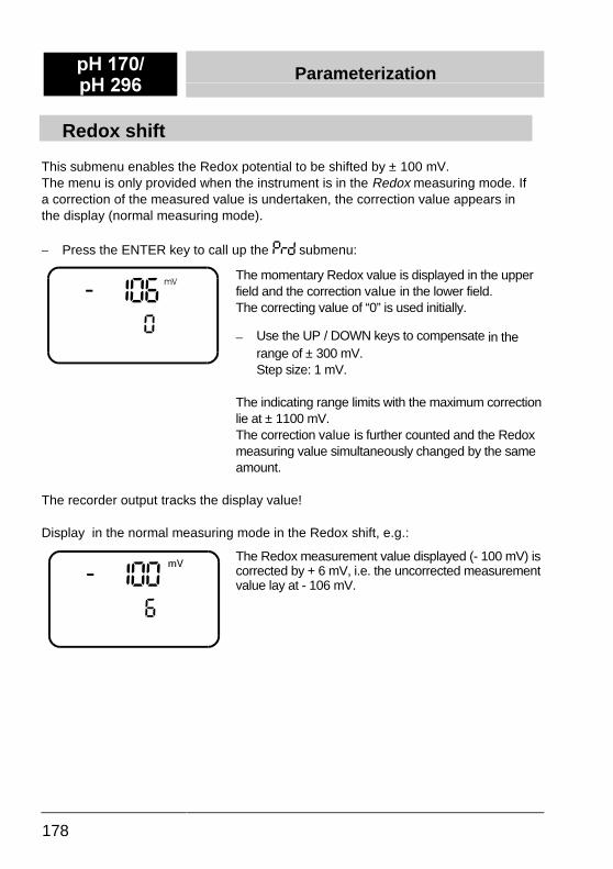
Redox shift
This submenu enables the Redox potential to be shifted by ± 100 mV.The menu is only provided when the instrument is in the Redox measuring mode. Ifa correction of the measured value is undertaken, the correction value appears inthe display (normal measuring mode).
-� Press the ENTER key to call up the -)& submenu:
The momentary Redox value is displayed in the upperfield and the correction value in the lower field.The correcting value of “0” is used initially.
-� Use the UP / DOWN keys to compensate in therange of ± 300 mV.Step size: 1 mV.
The indicating range limits with the maximum correctionlie at ± 1100 mV.The correction value is further counted and the Redoxmeasuring value simultaneously changed by the sameamount.
The recorder output tracks the display value!
Display in the normal measuring mode in the Redox shift, e.g.:
The Redox measurement value displayed (- 100 mV) iscorrected by + 6 mV, i.e. the uncorrected measurementvalue lay at - 106 mV.
Parameterization S+ ����S+ ���
179
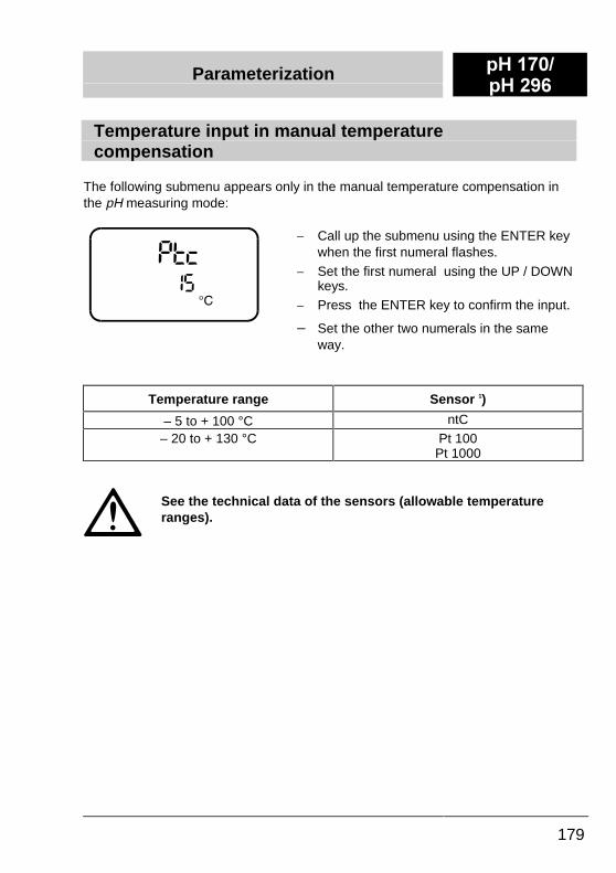
Temperature input in manual temperaturecompensation
The following submenu appears only in the manual temperature compensation inthe pH measuring mode:
-� Call up the submenu using the ENTER keywhen the first numeral flashes.
-� Set the first numeral using the UP / DOWNkeys.
-� Press the ENTER key to confirm the input.
-� Set the other two numerals in the sameway.
Temperature range Sensor 1)
– 5 to + 100 °C ntC– 20 to + 130 °C Pt 100
Pt 1000
See the technical data of the sensors (allowable temperatureranges).
S+ ����S+ ���
Parameterization
180
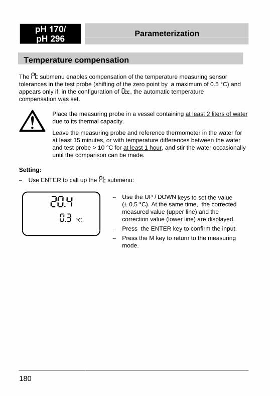
Temperature compensation
The -* submenu enables compensation of the temperature measuring sensortolerances in the test probe (shifting of the zero point by a maximum of 0.5 °C) andappears only if, in the configuration of , the automatic temperaturecompensation was set.
Place the measuring probe in a vessel containing at least 2 liters of waterdue to its thermal capacity.
Leave the measuring probe and reference thermometer in the water forat least 15 minutes, or with temperature differences between the waterand test probe > 10 °C for at least 1 hour, and stir the water occasionallyuntil the comparison can be made.
Setting:
-� Use ENTER to call up the -* submenu:
-� Use the UP / DOWN keys to set the value(� 0,5 °C). At the same time, the correctedmeasured value (upper line) and thecorrection value (lower line) are displayed.
-� Press the ENTER key to confirm the input.
-� Press the M key to return to the measuringmode.
Viewing Mode S+ ����S+ ���
181
Displaying the parameterization and configuration data
In the viewing mode, settings can be queried without having to input a code.However, the settings cannot be modified.
To leave the measuring mode and go into the viewing mode, perform the followingsteps:
-� Press the DOWN key.
-� Press the ENTER key when the first numeral flashes.
-� Press the ESCAPE key.
-� Use the UP / DOWN keys to change between the parameterization -� andconfiguration ��.
-� Press the ENTER key to run through the submenus.
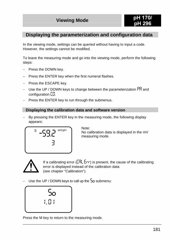
Displaying the calibration data and software version
-� By pressing the ENTER key in the measuring mode, the following displayappears:
Note:No calibration data is displayed in the mVmeasuring mode.
If a calibrating error (��/ �))) is present, the cause of the calibratingerror is displayed instead of the calibration data(see chapter “Calibration“).
-� Use the UP / DOWN keys to call up the �( submenu:
Press the M key to return to the measuring mode.
S+ ����S+ ���
Measuring Mode
182
The pH 170 and pH 296 instruments are automatically located in the measuringmode following the first commissioning.Otherwise, the measuring mode - except in compelled guidance - can be called upfrom any operating level by pressing the M key (see also section, Operatinginstructions).
Calibration S+ ����S+ ���
183
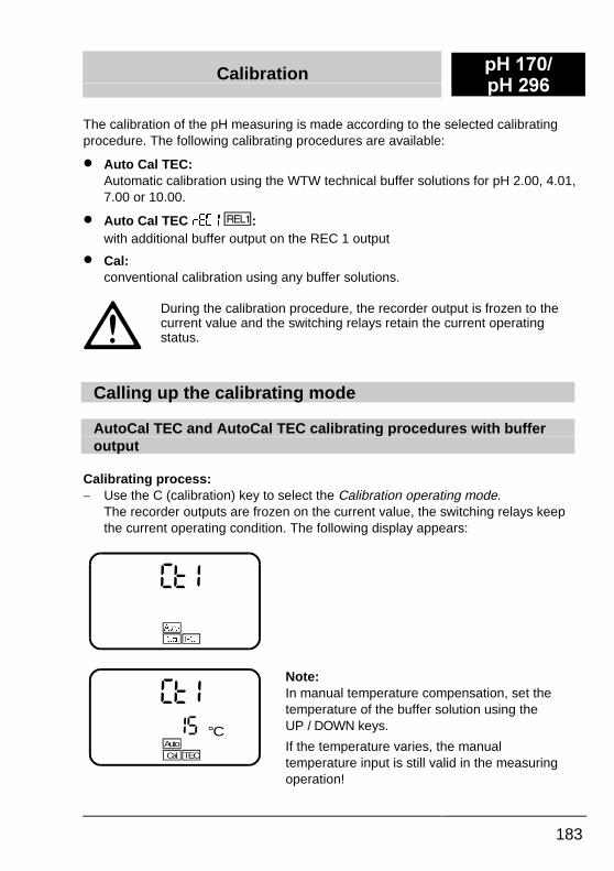
The calibration of the pH measuring is made according to the selected calibratingprocedure. The following calibrating procedures are available:
�� Auto Cal TEC:Automatic calibration using the WTW technical buffer solutions for pH 2.00, 4.01,7.00 or 10.00.
�� Auto Cal TEC )��� :with additional buffer output on the REC 1 output
�� Cal:conventional calibration using any buffer solutions.
During the calibration procedure, the recorder output is frozen to thecurrent value and the switching relays retain the current operatingstatus.
Calling up the calibrating mode
AutoCal TEC and AutoCal TEC calibrating procedures with bufferoutput
Calibrating process:-� Use the C (calibration) key to select the Calibration operating mode.
The recorder outputs are frozen on the current value, the switching relays keepthe current operating condition. The following display appears:
�*
7(&&DO
$XWR
�*�� °C
TECCal
Auto
Note:In manual temperature compensation, set thetemperature of the buffer solution using theUP / DOWN keys.
If the temperature varies, the manualtemperature input is still valid in the measuringoperation!
S+ ����S+ ���
Calibration
184
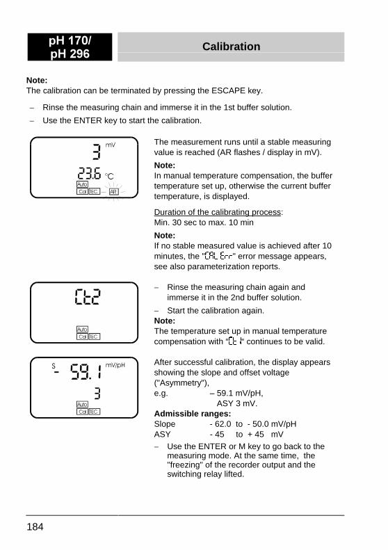
Note:The calibration can be terminated by pressing the ESCAPE key.
-� Rinse the measuring chain and immerse it in the 1st buffer solution.
-� Use the ENTER key to start the calibration.
The measurement runs until a stable measuringvalue is reached (AR flashes / display in mV).
Note:In manual temperature compensation, the buffertemperature set up, otherwise the current buffertemperature, is displayed.
Duration of the calibrating process:Min. 30 sec to max. 10 min
Note:If no stable measured value is achieved after 10minutes, the "��/ �))" error message appears,see also parameterization reports.
-� Rinse the measuring chain again andimmerse it in the 2nd buffer solution.
-� Start the calibration again.Note:The temperature set up in manual temperaturecompensation with “�*�“ continues to be valid.
After successful calibration, the display appearsshowing the slope and offset voltage("Asymmetry"),e.g. – 59.1 mV/pH,
ASY 3 mV.Admissible ranges:Slope - 62.0 to - 50.0 mV/pHASY - 45 to + 45 mV
-� Use the ENTER or M key to go back to themeasuring mode. At the same time, the"freezing" of the recorder output and theswitching relay lifted.
Calibration S+ ����S+ ���
185
In "AutoCal TEC" with buffer output, the buffer values are output viarelay 1 and recorder 1 (see AutoCal TEC with buffer output)
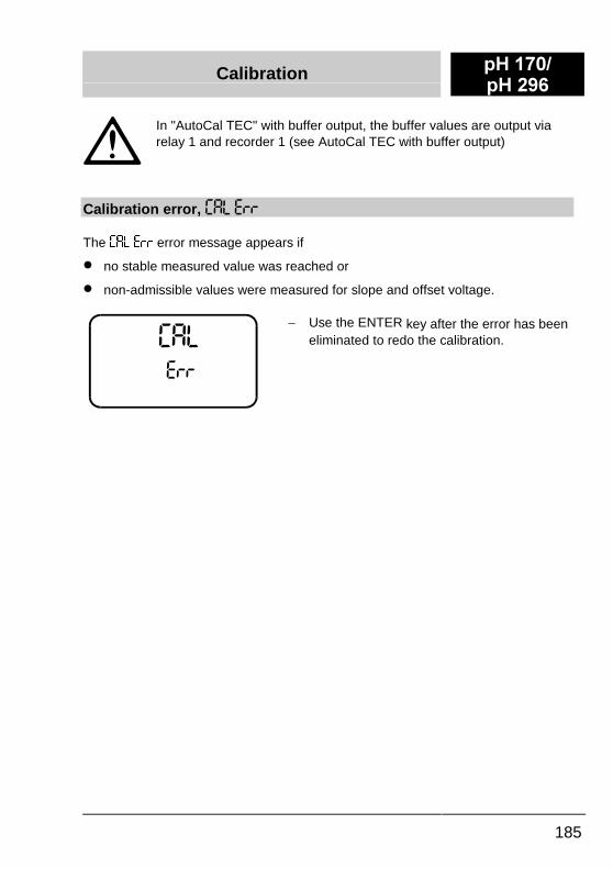
Calibration error, ��/ �))
The ��/ �)) error message appears if
�� no stable measured value was reached or
�� non-admissible values were measured for slope and offset voltage.
-� Use the ENTER key after the error has beeneliminated to redo the calibration.
S+ ����S+ ���
Calibration
186
AutoCal TEC with buffer valueAutoCal 2
REL 1
REL 1 pulled upREC 1 frozen
REL 1 pulled upREC 1 frozen
If the calibration is not o.k., REL 1remains pulled up and REC 1 frozenand a return is made to the start: "Start calibration".
READbuffer 1viaREC 1
READbuffer 2viaREC 1
Measuring
Displaybuffer 2
Displaybuffer 1
current meas. value
5 s 5 s
t
only ifcalibration o.k.
REC 1
Start ofcalibration
End ofcalibration
Buffer 1 Buffer 2
Techn.buffer 1
Techn.buffer 2
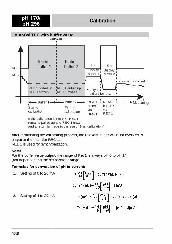
After terminating the calibrating process, the relevant buffer value for every 5s isoutput at the recorder REC 1.REL 1 is used for synchronization.
Note:For the buffer value output, the range of Rec1 is always pH 0 to pH 14(not dependent on the set recorder range).
Formulas for conversion of pH to current:
1. Setting of 0 to 20 mA ,� ����� P$ ���EXIIHU�YDOXH�>S+@�� S+> @
EXIIHU�YDOXH ��� �� S+ ���,�>P$@�� P$> @
2. Setting of 4 to 20 mA ,� ���>P$@������� P$ ���EXIIHU�YDOXH >S+@�� S+> @
EXIIHU�YDOXH ����� S+ ����,>P$@����>P$@��� P$> @
Calibration S+ ����S+ ���
187
Calibration using any buffer solutions: "ConCal"
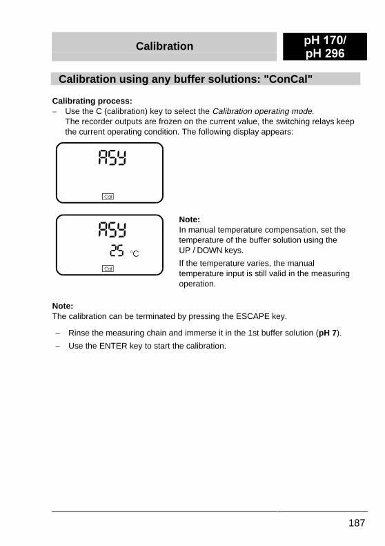
Calibrating process:-� Use the C (calibration) key to select the Calibration operating mode.
The recorder outputs are frozen on the current value, the switching relays keepthe current operating condition. The following display appears:
Note:In manual temperature compensation, set thetemperature of the buffer solution using theUP / DOWN keys.
If the temperature varies, the manualtemperature input is still valid in the measuringoperation.
Note:The calibration can be terminated by pressing the ESCAPE key.
-� Rinse the measuring chain and immerse it in the 1st buffer solution (pH 7).
-� Use the ENTER key to start the calibration.
S+ ����S+ ���
Calibration
188
Setting up the offset voltage ("Asymmetry" ASY)
����$� �&
S+
&DO
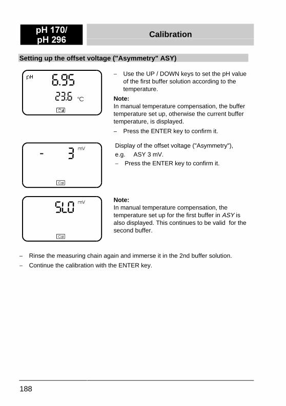
-� Use the UP / DOWN keys to set the pH valueof the first buffer solution according to thetemperature.
Note:In manual temperature compensation, the buffertemperature set up, otherwise the current buffertemperature, is displayed.
-� Press the ENTER key to confirm it.
Display of the offset voltage ("Asymmetry"),e.g. ASY 3 mV.-� Press the ENTER key to confirm it.
Note:In manual temperature compensation, thetemperature set up for the first buffer in ASY isalso displayed. This continues to be valid for thesecond buffer.
-� Rinse the measuring chain again and immerse it in the 2nd buffer solution.
-� Continue the calibration with the ENTER key.
Calibration S+ ����S+ ���
189
Setting up the measuring chain slope
����� °C
pH
Cal
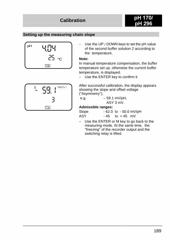
-� Use the UP / DOWN keys to set the pH valueof the second buffer solution 2 according tothe temperature.
Note:In manual temperature compensation, the buffertemperature set up, otherwise the current buffertemperature, is displayed.-� Use the ENTER key to confirm it
�#�� �&
6 P9�S+
&DO
After successful calibration, the display appearsshowing the slope and offset voltage("Asymmetry"),e.g. – 59.1 mV/pH,
ASY 3 mV.Admissible ranges:Slope - 62.0 to - 50.0 mV/pHASY - 45 to + 45 mV
-� Use the ENTER or M key to go back to themeasuring mode. At the same time, the"freezing" of the recorder output and theswitching relay is lifted.
S+ ����S+ ���
Calibration
190
Calibrating errors
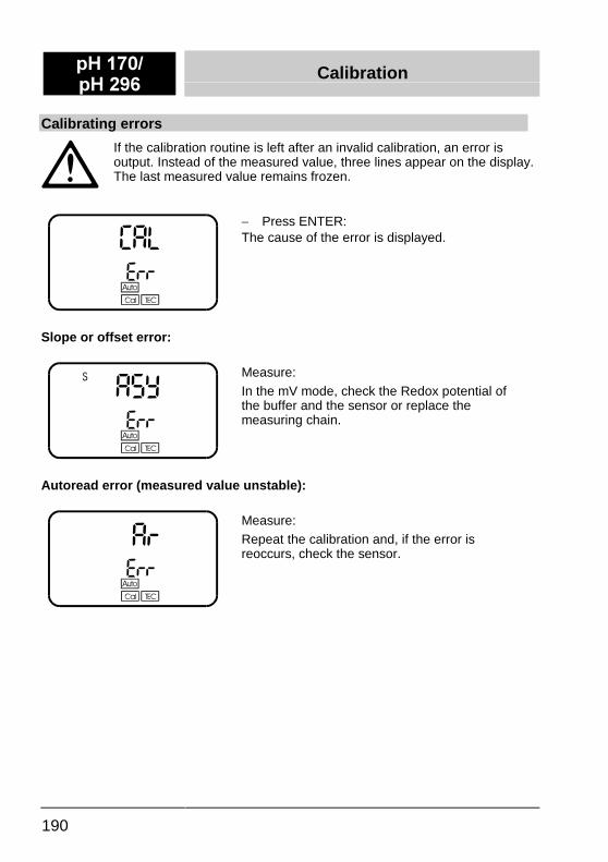
If the calibration routine is left after an invalid calibration, an error isoutput. Instead of the measured value, three lines appear on the display.The last measured value remains frozen.
-� Press ENTER:�The cause of the error is displayed.
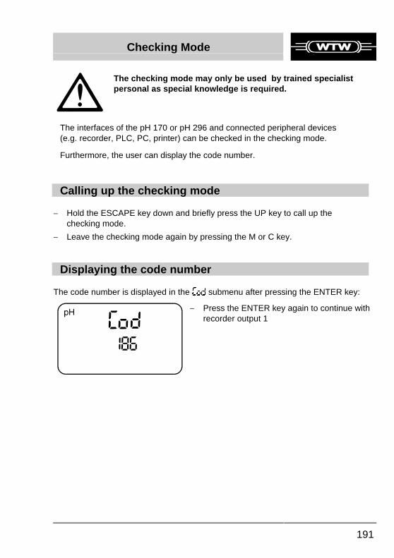
Slope or offset error:
Measure:In the mV mode, check the Redox potential ofthe buffer and the sensor or replace themeasuring chain.
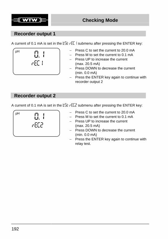
Autoread error (measured value unstable):
Measure:Repeat the calibration and, if the error isreoccurs, check the sensor.
Checking Mode
191
�
�The checking mode may only be used by trained specialistpersonal as special knowledge is required.�
��The interfaces of the pH 170 or pH 296 and connected peripheral devices(e.g. recorder, PLC, PC, printer) can be checked in the checking mode.��Furthermore, the user can display the code number.
�
Calling up the checking mode
-� Hold the ESCAPE key down and briefly press the UP key to call up thechecking mode.
-� Leave the checking mode again by pressing the M or C key.
Displaying the code number
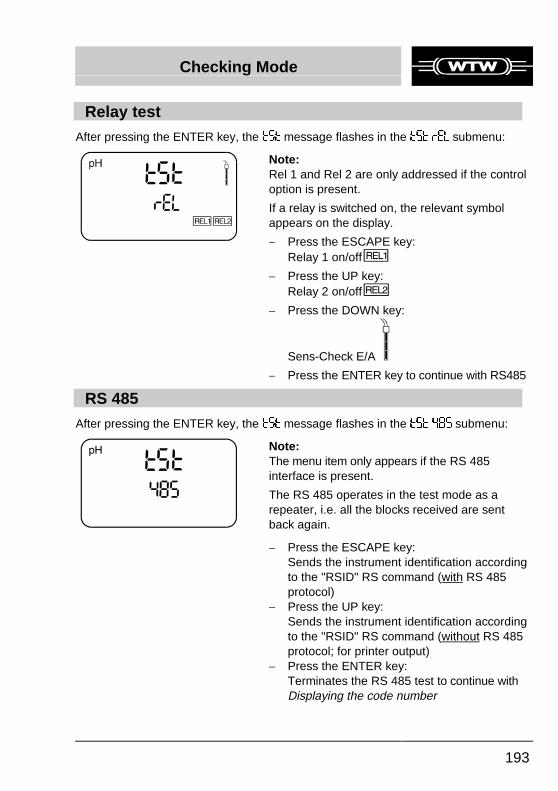
The code number is displayed in the �(& submenu after pressing the ENTER key:
-� Press the ENTER key again to continue withrecorder output 1
Checking Mode
192
Recorder output 1
A current of 0.1 mA is set in the *�* )��� submenu after pressing the ENTER key:
-� Press C to set the current to 20.0 mA-� Press M to set the current to 0.1 mA-� Press UP to increase the current
(max. 20.5 mA)-� Press DOWN to decrease the current
(min. 0.0 mA)-� Press the ENTER key again to continue with
recorder output 2
Recorder output 2
A current of 0.1 mA is set in the *�* )��� submenu after pressing the ENTER key:
-� Press C to set the current to 20.0 mA-� Press M to set the current to 0.1 mA-� Press UP to increase the current
(max. 20.5 mA)-� Press DOWN to decrease the current
(min. 0.0 mA)-� Press the ENTER key again to continue with
relay test.
Checking Mode
193
Relay test
After pressing the ENTER key, the *�* message flashes in the *�* )�/ submenu:
Note:Rel 1 and Rel 2 are only addressed if the controloption is present.
If a relay is switched on, the relevant symbolappears on the display.
-� Press the ESCAPE key:Relay 1 on/off
-� Press the UP key:Relay 2 on/off
-� Press the DOWN key:
Sens-Check E/A
-� Press the ENTER key to continue with RS485
RS 485
After pressing the ENTER key, the *�* message flashes in the *�* ��� submenu:
Note:The menu item only appears if the RS 485interface is present.
The RS 485 operates in the test mode as arepeater, i.e. all the blocks received are sentback again.
-� Press the ESCAPE key:Sends the instrument identification accordingto the "RSID" RS command (with RS 485protocol)
-� Press the UP key:Sends the instrument identification accordingto the "RSID" RS command (without RS 485protocol; for printer output)
-� Press the ENTER key:Terminates the RS 485 test to continue withDisplaying the code number
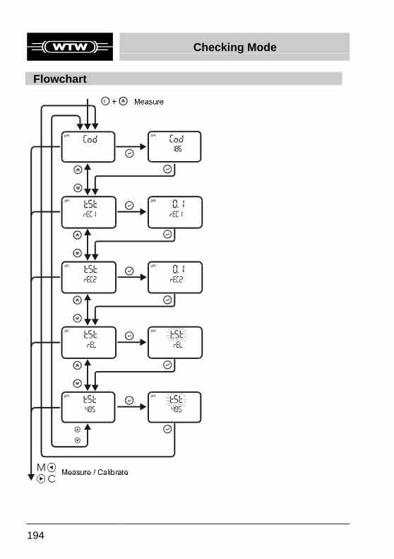
Checking Mode
194
Flowchart
0&
0HDVXUH���&DOLEUDWH
0HDVXUH�
Cleaning and Maintenance S+ ����S+ ���
195
The ph 170 and pH 296 instruments are largely maintenance-free.Some instructions are given here on taking care of the instruments:
-� Keep the instruments free from dust and dirt as far as possible.
-� Do not use a high-pressure cleaner to clean the housing.
-� Do not any cleaning agent that contains solvent.
-� Follow the details given in the sensor operating manual on cleaning andmaintenance of the sensors!
-� Check the instruments regularly for mechanical damage and, if necessary, takethem out of service.
-� Follow the safety instructions even when carrying out cleaning activities!
S+ ����S+ ���
Troubleshooting
196
The following messages could occur (shown in order of priority):
Message Reason Measure
�)) Serious error that does notpermit any further measuring
-� Send the instrument toWTW
��/
�))
No valid calibration exists -� Calibrate the instrumentagain (see also thechapter, Calibration)
��/ The pH/temperature value liesoutside the measuring range(Overflow)
-� Check the sensor andsensor connection
Measured valueflashes
An overflow is present on thecorresponding recorder output
-� Adapt the recorder range
Sensor possibly defective(only in the SensoLyt 700 andautomatic temperaturecompensation)
-� For help, see the sensoroperating manual
�))�(-*
Hardware error -� Send the instrument toWTW
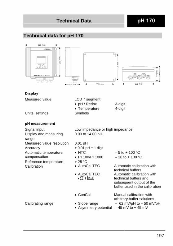
Technical Data
197
Technical data for pH 170
Display
Measured value LCD 7 segment�� pH / Redox 3-digit�� Temperature 4-digit
Units, settings Symbols
pH measurement
Signal input Low impedance or high impedanceDisplay and measuringrange
0.00 to 14.00 pH
Measured value resolution 0.01 pHAccuracy ± 0.01 pH ± 1 digitAutomatic temperaturecompensation
�� NTC – 5 to + 100 °C�� PT100/PT1000 – 20 to + 130 °C
Reference temperature + 25 °CCalibration �� AutoCal TEC Automatic calibration with
technical buffers�� AutoCal TEC Automatic calibration with)��� technical buffers and
subsequent output of thebuffer used in the calibration
�� ConCal Manual calibration witharbitrary buffer solutions
Calibrating range �� Slope range – 62 mV/pH to – 50 mV/pH�� Asymmetry potential – 45 mV to + 45 mV
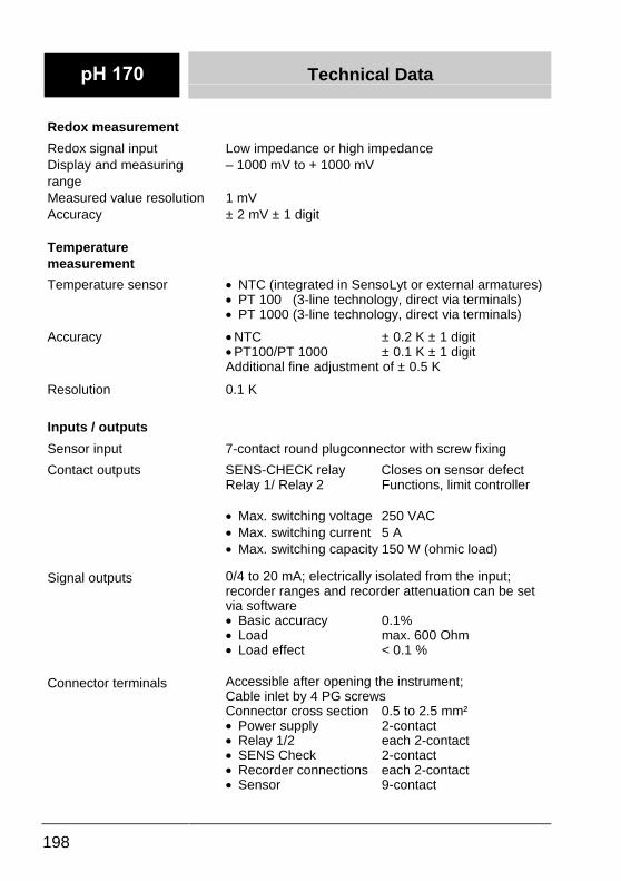
Technical Data
198
Redox measurement
Redox signal input Low impedance or high impedanceDisplay and measuringrange
– 1000 mV to + 1000 mV
Measured value resolution 1 mVAccuracy ± 2 mV ± 1 digit
Temperaturemeasurement
Temperature sensor �� NTC (integrated in SensoLyt or external armatures)�� PT 100 (3-line technology, direct via terminals)�� PT 1000 (3-line technology, direct via terminals)
Accuracy ��NTC ± 0.2 K ± 1 digit��PT100/PT 1000 ± 0.1 K ± 1 digitAdditional fine adjustment of ± 0.5 K
Resolution 0.1 K
Inputs / outputs
Sensor input 7-contact round plugconnector with screw fixing
Contact outputs SENS-CHECK relay Closes on sensor defectRelay 1/ Relay 2 Functions, limit controller
�� Max. switching voltage 250 VAC�� Max. switching current 5 A�� Max. switching capacity 150 W (ohmic load)
Signal outputs 0/4 to 20 mA; electrically isolated from the input;recorder ranges and recorder attenuation can be setvia software�� Basic accuracy 0.1%�� Load max. 600 Ohm�� Load effect < 0.1 %
Connector terminals Accessible after opening the instrument;Cable inlet by 4 PG screwsConnector cross section 0.5 to 2.5 mm²�� Power supply 2-contact�� Relay 1/2 each 2-contact�� SENS Check 2-contact�� Recorder connections each 2-contact�� Sensor 9-contact
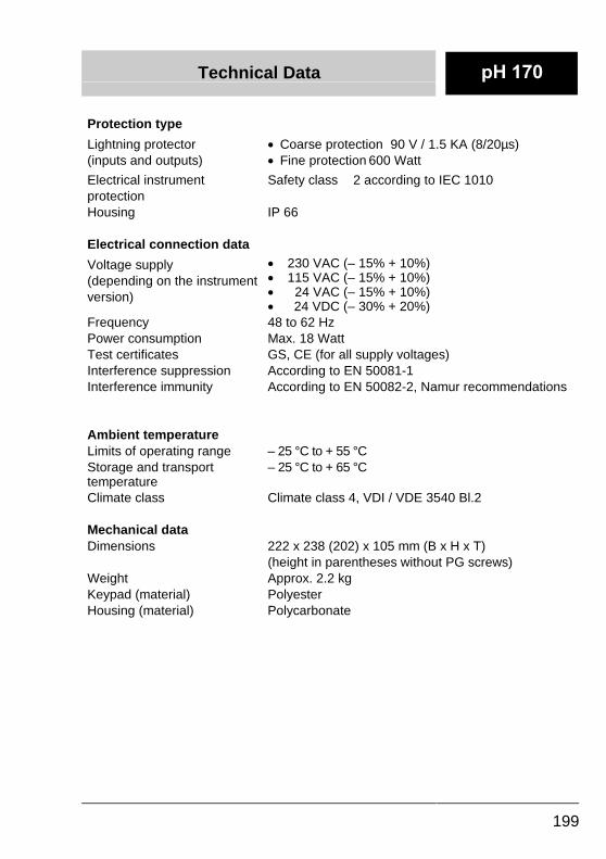
Technical Data
199
Protection type
Lightning protector(inputs and outputs)
�� Coarse protection 90 V / 1.5 KA (8/20µs)�� Fine protection 600 Watt
Electrical instrumentprotection
Safety class 2 according to IEC 1010
Housing IP 66
Electrical connection data
Voltage supply(depending on the instrumentversion)
�� 230 VAC (– 15% + 10%)�� 115 VAC (– 15% + 10%)�� 24 VAC (– 15% + 10%)�� 24 VDC (– 30% + 20%)
Frequency 48 to 62 HzPower consumption Max. 18 WattTest certificates GS, CE (for all supply voltages)Interference suppression According to EN 50081-1Interference immunity According to EN 50082-2, Namur recommendations
Ambient temperatureLimits of operating range – 25 °C to + 55 °CStorage and transporttemperature
– 25 °C to + 65 °C
Climate class Climate class 4, VDI / VDE 3540 Bl.2
Mechanical dataDimensions 222 x 238 (202) x 105 mm (B x H x T)
(height in parentheses without PG screws)Weight Approx. 2.2 kgKeypad (material) PolyesterHousing (material) Polycarbonate
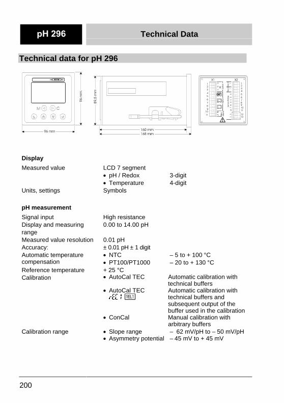
Technical Data
200
Technical data for pH 296
Display
Measured value LCD 7 segment�� pH / Redox 3-digit�� Temperature 4-digit
Units, settings Symbols
pH measurement
Signal input High resistanceDisplay and measuringrange
0.00 to 14.00 pH
Measured value resolution 0.01 pHAccuracy: ± 0.01 pH ± 1 digitAutomatic temperaturecompensation
�� NTC – 5 to + 100 °C�� PT100/PT1000 – 20 to + 130 °C
Reference temperature + 25 °CCalibration �� AutoCal TEC Automatic calibration with
technical buffers�� AutoCal TEC Automatic calibration with)��� technical buffers and
subsequent output of thebuffer used in the calibration
�� ConCal Manual calibration witharbitrary buffers
Calibration range �� Slope range – 62 mV/pH to – 50 mV/pH�� Asymmetry potential – 45 mV to + 45 mV
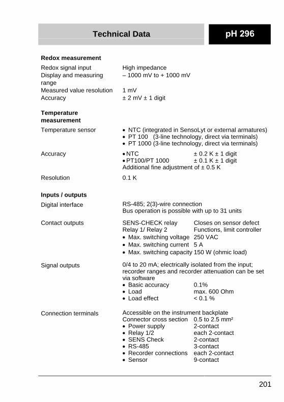
Technical Data
201
Redox measurement
Redox signal input High impedanceDisplay and measuringrange
– 1000 mV to + 1000 mV
Measured value resolution 1 mVAccuracy ± 2 mV ± 1 digit
Temperaturemeasurement
Temperature sensor �� NTC (integrated in SensoLyt or external armatures)�� PT 100 (3-line technology, direct via terminals)�� PT 1000 (3-line technology, direct via terminals)
Accuracy ��NTC ± 0.2 K ± 1 digit��PT100/PT 1000 ± 0.1 K ± 1 digitAdditional fine adjustment of ± 0.5 K
Resolution 0.1 K
Inputs / outputs
Digital interface RS-485; 2(3)-wire connectionBus operation is possible with up to 31 units
Contact outputs SENS-CHECK relay Closes on sensor defectRelay 1/ Relay 2 Functions, limit controller�� Max. switching voltage 250 VAC�� Max. switching current 5 A�� Max. switching capacity 150 W (ohmic load)
Signal outputs 0/4 to 20 mA; electrically isolated from the input;recorder ranges and recorder attenuation can be setvia software�� Basic accuracy 0.1%�� Load max. 600 Ohm�� Load effect < 0.1 %
Connection terminals Accessible on the instrument backplateConnector cross section 0.5 to 2.5 mm²�� Power supply 2-contact�� Relay 1/2 each 2-contact�� SENS Check 2-contact�� RS-485 3-contact�� Recorder connections each 2-contact�� Sensor 9-contact
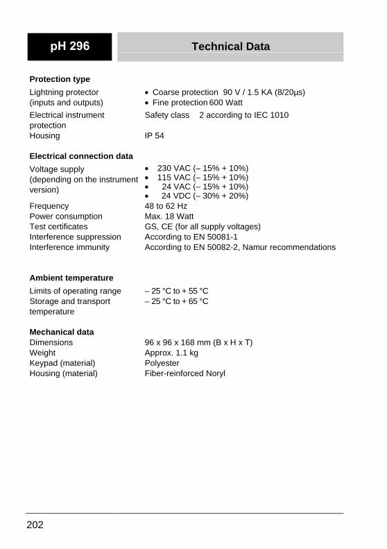
Technical Data
202
Protection type
Lightning protector(inputs and outputs)
�� Coarse protection 90 V / 1.5 KA (8/20µs)�� Fine protection 600 Watt
Electrical instrumentprotection
Safety class 2 according to IEC 1010
Housing IP 54
Electrical connection data
Voltage supply(depending on the instrumentversion)
�� 230 VAC (– 15% + 10%)�� 115 VAC (– 15% + 10%)�� 24 VAC (– 15% + 10%)�� 24 VDC (– 30% + 20%)
Frequency 48 to 62 HzPower consumption Max. 18 WattTest certificates GS, CE (for all supply voltages)Interference suppression According to EN 50081-1Interference immunity According to EN 50082-2, Namur recommendations
Ambient temperature
Limits of operating range – 25 °C to + 55 °CStorage and transporttemperature
– 25 °C to + 65 °C
Mechanical dataDimensions 96 x 96 x 168 mm (B x H x T)Weight Approx. 1.1 kgKeypad (material) PolyesterHousing (material) Fiber-reinforced Noryl


![Chapter 296-52 WAC - leg.wa.govleg.wa.gov/CodeReviser/WACArchive/Documents/2018/WAC 296 - 52 CHAPTER.… · (8/1/17) [ch. 296-52 wac p. 1] chapter 296-52 chapter 296-52 wac safety](https://img.pdfslide.net/doc/110x75/5e1c55c238ed802015030b5e/chapter-296-52-wac-legwa-296-52-chapter-8117-ch-296-52-wac-p-1.jpg)


![Chapter 296-841 Chapter 296-841 WAC AIRBORNE …lawfilesext.leg.wa.gov/law/WACArchive/2013/WAC-296-841-CHAPTE… · (2/20/07) [Ch. 296-841 WAC—p. 1] Chapter 296-841 Chapter 296-841](https://img.pdfslide.net/doc/110x75/605db1edd2831252ec0d5d41/chapter-296-841-chapter-296-841-wac-airborne-22007-ch-296-841-wacap-1.jpg)


![Chapter 296-19A Chapter 296-19A WAC VOCATIONAL …lawfilesext.leg.wa.gov/law/WACArchive/2012/WAC-296... · 296-19A-010 Vocational Rehabilitation [Ch. 296-19A WAC—p. 2] (11/15/11)](https://img.pdfslide.net/doc/110x75/6013de7783e2d5485a5626ed/chapter-296-19a-chapter-296-19a-wac-vocational-296-19a-010-vocational-rehabilitation.jpg)


![Wtw Ol Man Monitors Cond 170 296 All[1]](https://img.pdfslide.net/doc/110x75/55cf8cf85503462b1390d229/wtw-ol-man-monitors-cond-170-296-all1.jpg)