Embed Size (px)
Citation preview
PHASET ECHNOLOG I E S
INTUITIVELYENGINEERED
Low Harmonic | Phase Converting | Three-Phase
VARIABLE FREQUENCY DRIVES
Operation & Installation Manual
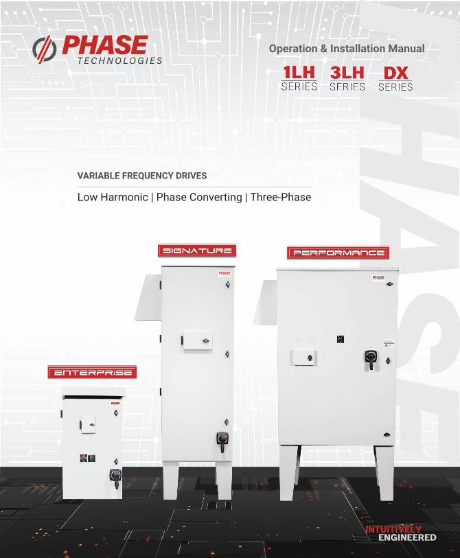
Product Manual Variable Frequency Drives
20 HP to 200 HP 20 HP to 450 HP
3R Package
Low Harmonic
IEEE 519 Compliant
Phase Converting
Voltage Doubling
3R Package
Low Harmonic
IEEE 519 Compliant
Three Phase
Voltage Doubling
Six-Pulse
Three Phase
3R Package
CONTACT INFORMATION
Address: 222 Disk Drive, Rapid City, SD 57701
Phone: 605-343-7934 Fax: 605-343-7943 Toll Free: 866-250-7934
www.phasetechnologies.com
5 HP to 50 HP
2020 © Copyright. V2.5 All rights reserved. All contents are property of Phase Technologies, LLC.
No portion of this publication or its contents may be duplicated by any means, electronic or otherwise, without the express written consent of Phase Technologies, LLC.
#3187280
ii | P a g e
SAFETY MESSAGES AND WARNINGS
To ensure safe and reliable operation of the 1LH, 3LH and DX Series variable frequency drives, it is important to carefully read this manual and to read and observe all warning labels attached to the drive before installing the equipment. Please follow all instructions exactly and keep this manual with the equipment at all times for quick and easy reference.
Definitions of Warning Signs and Symbols
CAUTION: Indicates a potentially hazardous situation that could result in injury or damage to the product.
WARNING: Indicates a potentially hazardous situation that could result in serious injury or death.
HIGH VOLTAGE: Indicates high voltage. The voltage associated with the procedures or operations referenced could result in serious injury or death. Use caution and follow instructions carefully.
READ THESE WARNINGS BEFORE INSTALLING OR OPERATING EQUIPMENT!
WARNING: Risk of electric shock. De-energize the unit by disconnecting all incoming sources of power, then wait 10 minutes for internal charges to dissipate before servicing the equipment.
HIGH VOLTAGE: This equipment is connected to line voltages that can create a potentially hazardous situation. Electric shock could result in serious injury or death. This device should be installed only by trained, licensed and qualified personnel. Follow instructions carefully and observe all warnings.
WARNING: This equipment should be installed and serviced by qualified personnel familiar with the type of equipment and experienced in working with dangerous voltages.
WARNING: Installation of this equipment must comply with the National Electrical Code (NEC) and all applicable local codes. Failure to observe and comply with these codes could result in risk of electric shock, fire or damage to the equipment.
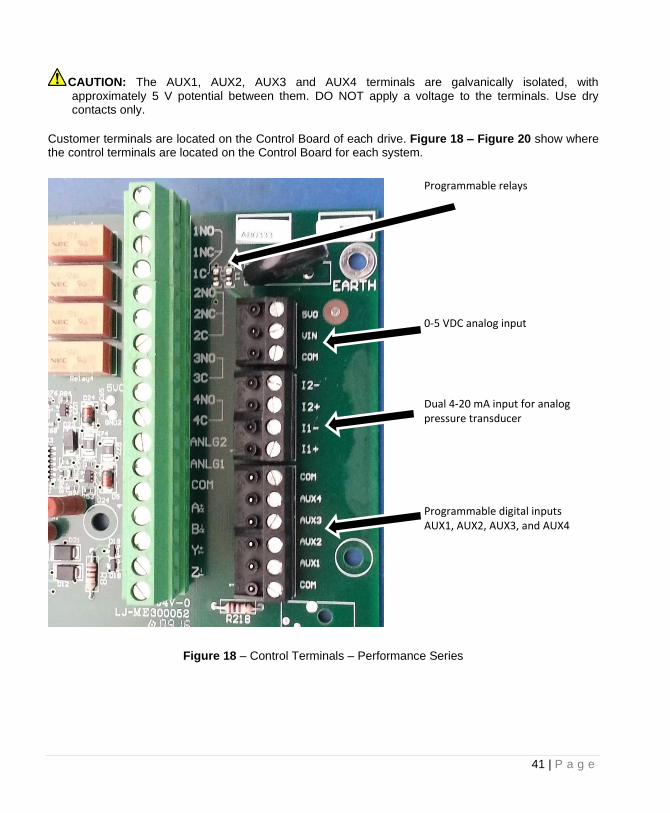
CAUTION: The AUX1 through AUX4 terminals are galvanically isolated, with approximately 5V potential between them. DO NOT apply a voltage to the terminals. Use dry contacts only.
CAUTION: Circuit breakers or fuses, proper ground circuits, disconnect and other safety equipment and their proper installation are not provided by Phase Technologies, LLC, and are the responsibility of the end user.
iii | P a g e
CAUTION: Long leads between the unit and the motor with an unfiltered PWM voltage can lead to dangerous voltage rise from reflected harmonics. Very long leads, such as in deep well submersible pump applications, may require the use of a sine wave filter to remove most of the harmonics from the waveform. Consult the factory or a knowledgeable source on drive filters if your application has more than 50 feet between the drive and the motor.
CAUTION: Failure to maintain adequate clearance may lead to overheating of the unit and cause damage or fire.
WARNING: Suitable for use in a circuit capable of delivering not more than 10 kA RMS symmetrical amperes, 480 VAC.
WARNING: Wire used within the motor circuit and all field wiring terminals must be rated at least 75 C.
WARNING: Use wire size suitable for Class 1 circuits.
WARNING: Input power connections should be made by a qualified electrician into a nominal 480V circuit for models with 460V input, with adequate current carrying capacity. Branch circuit protection to the drive should be provided by appropriate size fuses or circuit breaker. Circuit breaker and fuse ratings for each model are listed in Table 13.
WARNING: These devices are equipped with integral solid state short circuit protection. Integral solid state short circuit protection does not provide branch circuit protection. Branch circuit protection must be provided in accordance with the National Electrical Code and any additional local codes.
CAUTION: Use 600 V vinyl-sheathed wire or equivalent. The voltage drop of the leads needs to be considered in determining wire size. Voltage drop is dependent on wire length and gauge. Use copper conductors only.
CAUTION: Wires fastened to the terminal blocks shall be secured by tightening the terminal screws to a torque value listed in Table 11 and Table 12.
CAUTION: The maximum wire gauge for the input terminals is listed in Table 11.
CAUTION: Never allow bare wire to contact the metal surfaces.
CAUTION: Never connect AC main power to the output terminals U/T1, V/T2, and W/T3.
WARNING: Under certain conditions, the motor may automatically restart after a trip has stopped it. Make sure power to the drive has been disconnected before approaching or servicing the equipment. Otherwise, serious injury may occur.
iv | P a g e
CAUTION: Use caution when applying power to the main input terminals of the unit. If the drive is programmed to allow automatic restarts, the drive will initialize in AUTO mode and the motor load may start as soon as the drive is energized.
CAUTION: The AC motor load must be connected directly to the output terminals of the drive. Do not install relays or disconnect switches between the drive and the motor load.
CAUTION: Before the motor is connected to the output terminals, check all output lines for line-to-ground faults using a megger. There is a direct path through the drive circuitry for ground fault currents that can be triggered when power is applied to the input terminals, even though the output switches are not activated. These currents can cause serious damage to drive circuitry and are not covered under warranty.
CAUTION: Before touching any printed circuit board, place a hand on a bare metal surface of the unit to discharge any static electricity. Electrostatic discharge (ESD) can damage printed circuits and their components.
CAUTION: When the ENABLE RESTARTS parameter is enabled the drive will energize in AUTO mode. The motor load may automatically run as soon as the drive is energized. To stop the motor, push the STIOP/OFF key until the display indicates MANUAL or OFF, or open AUX1 or AUX2. The RUN and STOP keys only work when in MAN mode. Refer to the section on Keypad and Display for instructions on operating the keypad.
CAUTION: Operating the system in MANUAL mode on the keypad overrides remote signals from any remote controls. Operating the system in this mode may lead to dangerous pressures in closed plumbing systems
CAUTION: Line Filter Capacitors Line filter capacitors should be inspected annually at a minimum. If they are degraded the electrical noise can damage equipment connected to the drive. See Section 9 for details.
v | P a g e
TABLE OF CONTENTS
INTRODUCTION ................................................................................................................................... 1
MODELS AND RATINGS ..................................................................................................................... 4
2.1 Model Nomenclature ...................................................................................................... 4
2.2 Model Ratings ............................................................................................................... 10
2.3 Dimensional Drawings .................................................................................................. 20
INSTALLATION .................................................................................................................................. 32
3.1 Mounting ....................................................................................................................... 32
3.2 General Wiring Considerations ..................................................................................... 33
3.3 Installing Power Cables ................................................................................................. 39
3.4 Control Terminals .......................................................................................................... 40
KEYPAD & DISPLAY ......................................................................................................................... 49
4.1 Using the Keypad and Display ....................................................................................... 49
4.2 Keypad Main Menu Items ............................................................................................. 51
4.3 Change Parameter Values ............................................................................................. 53
4.4 Read Measured Values ................................................................................................. 54
4.5 Read Timers................................................................................................................... 56
4.6 Restart Log .................................................................................................................... 58
4.7 Fault Log ........................................................................................................................ 59
4.8 Clear Memory ............................................................................................................... 60
ADJUSTABLE PARAMETERS .......................................................................................................... 61
5.1 Changing Parameter Values .......................................................................................... 61
5.2 Restore Default Parameter Settings ............................................................................. 63
5.3 Auto Restarts ................................................................................................................. 63
5.4 All Parameters List ........................................................................................................ 76
vi | P a g e
5.5 Changed Parameter List ................................................................................................ 76
OPERATION ....................................................................................................................................... 77
6.1 Commissioning the Unit ................................................................................................ 77
6.2 Ground Fault Detection ................................................................................................. 77
6.3 Motor Overload Protection ........................................................................................... 79
6.4 System Configuration .................................................................................................... 79
6.5 Start-Up and Shut-Down Ramp Times ........................................................................... 81
6.6 Motor Control Methods (V/f vs. Torque Control Specific To V-Series Products) .......... 83
CONSTANT PRESSURE SYSTEMS .................................................................................................. 84
7.1 Control Principles of Constant Pressure Systems .......................................................... 84
7.2 Troubleshooting Constant Pressure Systems ................................................................ 86
7.3 PerfectPressure™ Setup – Analog Constant Pressure ................................................... 88
7.4 Digital Constant Pressure Systems ................................................................................ 89
7.5 Analog Constant Pressure Systems ............................................................................... 92
7.6 Pre-Charge Mode .......................................................................................................... 96
7.7 Lead/Lag Pump Control ................................................................................................. 97
7.8 Duplex / Multiplex Control .......................................................................................... 100
TROUBLESHOOTING ...................................................................................................................... 104
8.1 Fault Codes .................................................................................................................. 104
8.2 Clearing a Fault ............................................................................................................ 105
ROUTINE INSPECTION AND MAINTENANCE ............................................................................... 109
1 | P a g e
INTRODUCTION
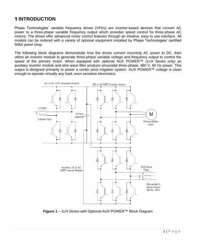
Phase Technologies’ variable frequency drives (VFDs) are inverter-based devices that convert AC power to a three-phase variable frequency output which provides speed control for three-phase AC motors. The drives offer advanced motor control features through an intuitive, easy to use interface. All models can be ordered with a variety of optional equipment installed by Phase Technologies’ certified 508A panel shop.
The following block diagrams demonstrate how the drives convert incoming AC power to DC, then utilize an inverter module to generate three-phase variable voltage and frequency output to control the speed of the primary motor. When equipped with optional AUX POWER™ (1LH Series only) an auxiliary inverter module and sine wave filter produce sinusoidal three-phase, 480 V, 60 Hz power. This output is designed primarily to power a center pivot irrigation system. AUX POWER™ voltage is clean enough to operate virtually any load, even sensitive electronics.
Figure 1 – 1LH Series with Optional AUX POWER™ Block Diagram
2 | P a g e
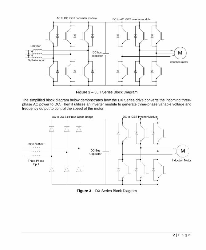
Figure 2 – 3LH Series Block Diagram
The simplified block diagram below demonstrates how the DX Series drive converts the incoming three-phase AC power to DC. Then it utilizes an inverter module to generate three-phase variable voltage and frequency output to control the speed of the motor.
Figure 3 – DX Series Block Diagram
3 | P a g e
FEATURES Low Line Side Harmonics (IEEE 519-2014 Compliant) – 1LH & 3LH Only All models of the LH series employ active front end (AFE) technology. Active switching of the input IGBTs allows the drive to draw the input current as a sine wave, greatly reducing the current distortion and line harmonics associated with a diode bridge rectifier. Because of its favorable harmonic profile, input line reactors and harmonic filters are NOT REQUIRED on the line side of the drive. Installations at 50% load or greater will comply with IEEE 519, the international standard for allowable harmonic distortion on utility mains. Voltage Doubling – All Series Unlike a diode bridge rectifier, the input module is capable of significantly boosting the voltage on the DC bus. Utilizing this feature, some models of the series convert 240 V, single-phase or 240 V, three phase line voltage to 480 V, three-phase output. 20 HP and 30 HP models are rated either 240 V or 480 V on the line side. All drives in the series are rated 480 V, three-phase on the load side. DC Link Film Capacitors – All Series The drives utilize film capacitors on the DC bus, whereas most other drives use electrolytic capacitors. Film capacitors are more robust than electrolytics, providing better tolerance to overvoltage and a much longer life. These drives are more reliable and will last longer than a drive with electrolytic bus capacitors. Input Reactor – All Series An input reactor is a standard feature on all DX and LH Series VFD’s. The input reactor is an inductor connected in series between the input terminals and the diode or IGBT rectifier. The input reactor reduces harmonics on the input lines, protects the input stage from current surges, and reduces ripple current on the DC bus. It offers some protection against voltage transients, but installation of a surge protective device (SPD) is recommended to protect the system from surges. Load Side Inverter – All Series The output on the load side is three-phase, pulse width modulated (PWM), variable voltage and frequency. All models are rated 480 V. Superior Heat Rejection: Indirect Cooling – All Series The drive and enclosure are thermally engineered with an indirect cooling design. Assembled as one unit, the design directs air flow over critical heat-producing components while isolating sensitive components from outside ambient air. Most other outdoor 3R rated drives integrate a NEMA 1 indoor VFD in an outdoor enclosure without segregating the airflow. With this design, the drive and other sensitive components can be degraded due to re-circulated hot air and contaminants from outside air. AUX POWER™ - 1LH Only 1LH Series phase-converting drives are available with optional AUX POWER™, a sinusoidal, 60 Hz, 480 V, three-phase output. When equipped with AUX POWER™, the drive provides full-featured speed control of the main pump plus an independently-controlled phase converter designed to provide power to a center pivot irrigation system. AUX POWER™ output can also be used for other loads that require clean, sinusoidal power.
4 | P a g e
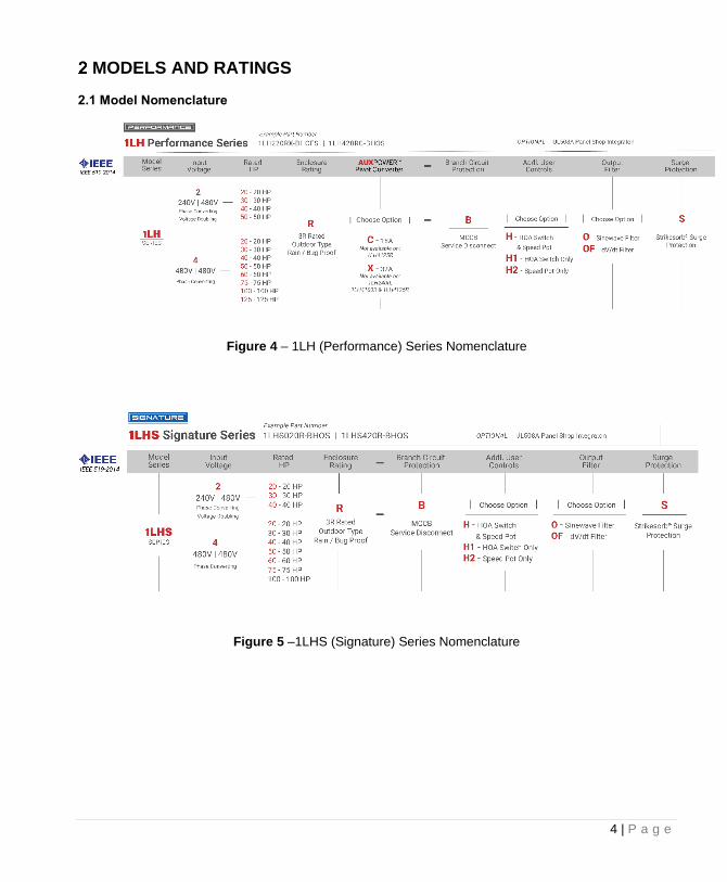
MODELS AND RATINGS 2.1 Model Nomenclature
Figure 4 – 1LH (Performance) Series Nomenclature
Figure 5 –1LHS (Signature) Series Nomenclature
5 | P a g e
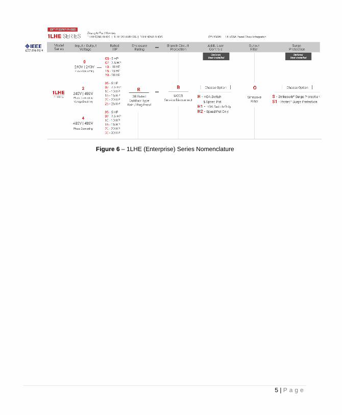
Figure 6 – 1LHE (Enterprise) Series Nomenclature
6 | P a g e
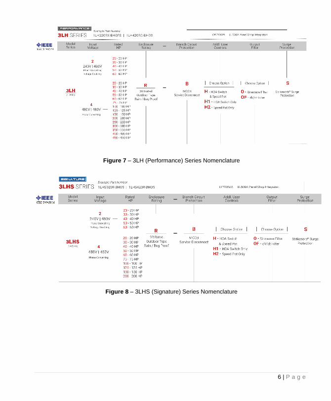
Figure 7 – 3LH (Performance) Series Nomenclature
Figure 8 – 3LHS (Signature) Series Nomenclature
7 | P a g e
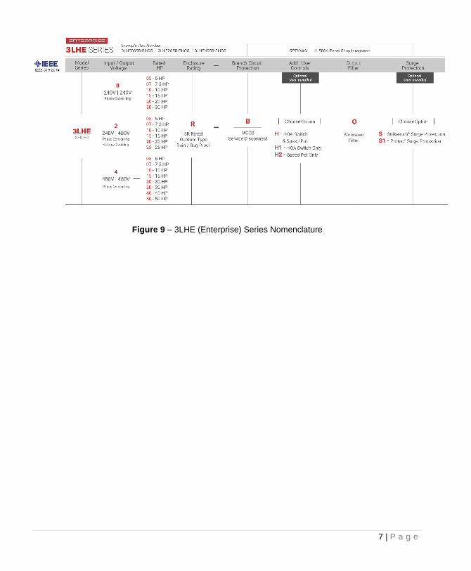
Figure 9 – 3LHE (Enterprise) Series Nomenclature
8 | P a g e
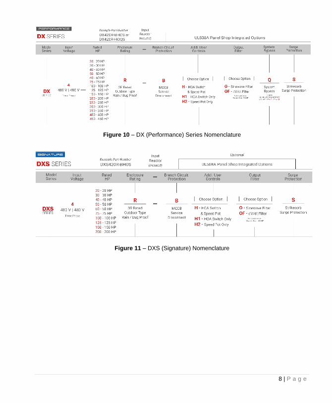
Figure 10 – DX (Performance) Series Nomenclature
Figure 11 – DXS (Signature) Nomenclature
9 | P a g e
Figure 12 – DXE (Enterprise) Series Nomenclature
10 | P a g e
2.2 Model Ratings
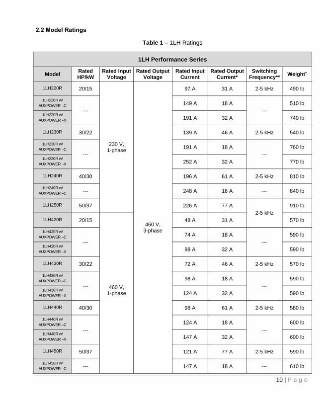
Table 1 – 1LH Ratings
1LH Performance Series
Model Rated HP/kW
Rated Input Voltage
Rated Output Voltage
Rated Input Current
Rated Output Current*
Switching Frequency**
Weight†
1LH220R 20/15
230 V, 1-phase
460 V, 3-phase
97 A 31 A 2-5 kHz 490 lb
1LH220R w/
AUXPOWER –C
---
149 A 18 A
---
510 lb
1LH220R w/
AUXPOWER –X 191 A 32 A 740 lb
1LH230R 30/22 139 A 46 A 2-5 kHz 540 lb
1LH230R w/
AUXPOWER –C ---
191 A 18 A
---
760 lb
1LH230R w/
AUXPOWER –X 252 A 32 A 770 lb
1LH240R 40/30 196 A 61 A 2-5 kHz 810 lb
1LH240R w/
AUXPOWER –C --- 248 A 18 A --- 840 lb
1LH250R 50/37 226 A 77 A
2-5 kHz
910 lb
1LH420R 20/15
460 V, 1-phase
48 A 31 A 570 lb
1LH420R w/
AUXPOWER –C ---
74 A 18 A
---
590 lb
1LH420R w/
AUXPOWER –X 98 A 32 A 590 lb
1LH430R 30/22 72 A 46 A 2-5 kHz 570 lb
1LH430R w/
AUXPOWER –C ---
98 A 18 A
---
590 lb
1LH430R w/
AUXPOWER –X 124 A 32 A 590 lb
1LH440R 40/30 98 A 61 A 2-5 kHz 580 lb
1LH440R w/
AUXPOWER –C ---
124 A 18 A
---
600 lb
1LH440R w/
AUXPOWER –X 147 A 32 A 600 lb
1LH450R 50/37 121 A 77 A 2-5 kHz 590 lb
1LH450R w/
AUXPOWER –C --- 147 A 18 A --- 610 lb
11 | P a g e
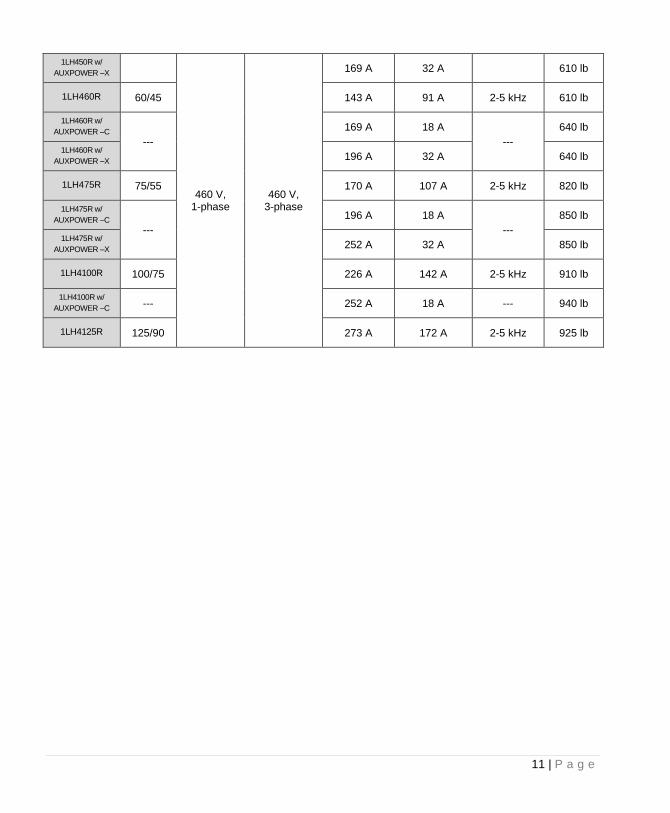
1LH450R w/
AUXPOWER –X
460 V, 1-phase
460 V, 3-phase
169 A 32 A 610 lb
1LH460R 60/45 143 A 91 A 2-5 kHz 610 lb
1LH460R w/
AUXPOWER –C ---
169 A 18 A
---
640 lb
1LH460R w/
AUXPOWER –X 196 A 32 A 640 lb
1LH475R 75/55 170 A 107 A 2-5 kHz 820 lb
1LH475R w/
AUXPOWER –C ---
196 A 18 A
---
850 lb
1LH475R w/
AUXPOWER –X 252 A 32 A 850 lb
1LH4100R 100/75 226 A 142 A 2-5 kHz 910 lb
1LH4100R w/
AUXPOWER –C --- 252 A 18 A --- 940 lb
1LH4125R 125/90 273 A 172 A 2-5 kHz 925 lb
12 | P a g e
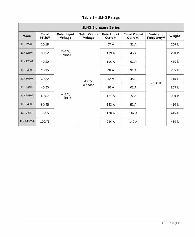
Table 2 – 1LHS Ratings
1LHS Signature Series
Model Rated HP/kW
Rated Input Voltage
Rated Output Voltage
Rated Input Current
Rated Output Current*
Switching Frequency**
Weight†
1LHS220R 20/15
230 V, 1-phase
460 V, 3-phase
97 A 31 A
2-5 kHz
205 lb
1LHS230R 30/22 139 A 46 A 220 lb
1LHS240R 40/30 196 A 61 A 465 lb
1LHS420R 20/15
460 V, 1-phase
48 A 31 A 205 lb
1LHS430R 30/22 72 A 46 A 215 lb
1LHS440R 40/30 98 A 61 A 235 lb
1LHS450R 50/37 121 A 77 A 250 lb
1LHS460R 60/45 143 A 91 A 410 lb
1LHS475R 75/55 170 A 107 A 415 lb
1LHS4100R 100/75 226 A 142 A 465 lb
13 | P a g e
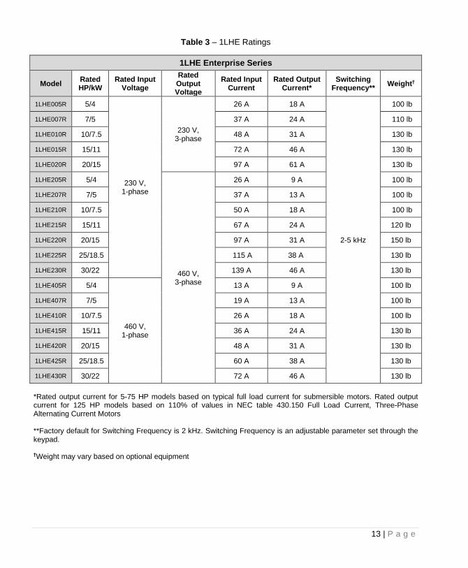
Table 3 – 1LHE Ratings
1LHE Enterprise Series
Model Rated HP/kW
Rated Input Voltage
Rated Output Voltage
Rated Input Current
Rated Output Current*
Switching Frequency**
Weight†
1LHE005R 5/4
230 V, 1-phase
230 V, 3-phase
26 A 18 A
2-5 kHz
100 lb
1LHE007R 7/5 37 A 24 A 110 lb
1LHE010R 10/7.5 48 A 31 A 130 lb
1LHE015R 15/11 72 A 46 A 130 lb
1LHE020R 20/15 97 A 61 A 130 lb
1LHE205R 5/4
460 V, 3-phase
26 A 9 A 100 lb
1LHE207R 7/5 37 A 13 A 100 lb
1LHE210R 10/7.5 50 A 18 A 100 lb
1LHE215R 15/11 67 A 24 A 120 lb
1LHE220R 20/15 97 A 31 A 150 lb
1LHE225R 25/18.5 115 A 38 A 130 lb
1LHE230R 30/22 139 A 46 A 130 lb
1LHE405R 5/4
460 V, 1-phase
13 A 9 A 100 lb
1LHE407R 7/5 19 A 13 A 100 lb
1LHE410R 10/7.5 26 A 18 A 100 lb
1LHE415R 15/11 36 A 24 A 130 lb
1LHE420R 20/15 48 A 31 A 130 lb
1LHE425R 25/18.5 60 A 38 A 130 lb
1LHE430R 30/22 72 A 46 A 130 lb
*Rated output current for 5-75 HP models based on typical full load current for submersible motors. Rated output current for 125 HP models based on 110% of values in NEC table 430.150 Full Load Current, Three-Phase Alternating Current Motors **Factory default for Switching Frequency is 2 kHz. Switching Frequency is an adjustable parameter set through the keypad. †Weight may vary based on optional equipment
14 | P a g e
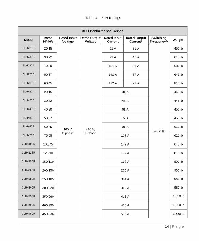
Table 4 – 3LH Ratings
3LH Performance Series
Model Rated HP/kW
Rated Input Voltage
Rated Output Voltage
Rated Input Current
Rated Output Current*
Switching Frequency**
Weight†
3LH220R 20/15
460 V, 3-phase
460 V, 3-phase
61 A 31 A
2-5 kHz
450 lb
3LH230R 30/22 91 A 46 A 615 lb
3LH240R 40/30 121 A 61 A 630 lb
3LH250R 50/37 142 A 77 A 645 lb
3LH260R 60/45 172 A 91 A 810 lb
3LH420R 20/15 31 A 445 lb
3LH430R 30/22 46 A 445 lb
3LH440R 40/30 61 A 450 lb
3LH450R 50/37 77 A 450 lb
3LH460R 60/45 91 A 615 lb
3LH475R 75/55 107 A 620 lb
3LH4100R 100/75 142 A 645 lb
3LH4125R 125/90 172 A 810 lb
3LH4150R 150/110 198 A 890 lb
3LH4200R 200/150 250 A 935 lb
3LH4250R 250/185 304 A 950 lb
3LH4300R 300/220 362 A 980 lb
3LH4350R 350/260 415 A 1,050 lb
3LH4400R 400/299 478 A 1,320 lb
3LH4450R 450/336 515 A 1,330 lb
15 | P a g e
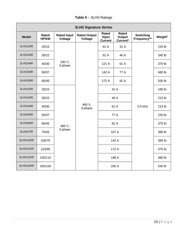
Table 5 – 3LHS Ratings
3LHS Signature Series
Model Rated HP/kW
Rated Input Voltage
Rated Output Voltage
Rated Input
Current
Rated Output
Current*
Switching Frequency**
Weight†
3LHS220R 20/15
230 V, 3-phase
460 V, 3-phase
61 A 31 A
2-5 kHz
220 lb
3LHS230R 30/22 91 A 46 A 340 lb
3LHS240R 40/30 121 A 61 A 370 lb
3LHS250R 50/37 142 A 77 A 480 lb
3LHS260R 60/45 172 A 91 A 530 lb
3LHS420R 20/15
460 V, 3-phase
31 A 180 lb
3LHS430R 30/22 46 A 210 lb
3LHS440R 40/30 61 A 215 lb
3LHS450R 50/37 77 A 220 lb
3LHS460R 60/45 91 A 375 lb
3LHS475R 75/55 107 A 380 lb
3LHS4100R 100/75 142 A 385 lb
3LHS4125R 125/90 172 A 475 lb
3LHS4150R 150/110 198 A 480 lb
3LHS4200R 200/150 250 A 540 lb
16 | P a g e
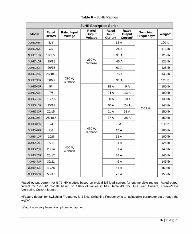
Table 6 – 3LHE Ratings
3LHE Enterprise Series
Model Rated
HP/KW Rated Input
Voltage
Rated Output Voltage
Rated Input
Current
Rated Output
Current*
Switching Frequency**
Weight†
3LHE005R 5/4
230 V, 3-phase
230 V, 3-phase
18 A
2-5 kHz
100 lb
3LHE007R 7/5 24 A 115 lb
3LHE010R 10/7.5 31 A 125 lb
3LHE015R 15/11 46 A 125 lb
3LHE020R 20/15 61 A 125 lb
3LHE025R 25/18.5 75 A 145 lb
3LHE030R 30/22 91 A 145 lb
3LHE205R 5/4
460 V, 3-phase
18 A 9 A 100 lb
3LHE207R 7/5 24 A 13 A 100 lb
3LHE210R 10/7.5 30 A 18 A 130 lb
3LHE215R 15/11 46 A 24 A 140 lb
3LHE220R 20/15 61 A 31 A 150 lb
3LHE225R 25/18.5 77 A 38 A 150 lb
3LHE405R 5/4
460 V, 3-phase
9 A 100 lb
3LHE407R 7/6 13 A 100 lb
3LHE410R 10/8 18 A 100 lb
3LHE415R 15/11 24 A 125 lb
3LHE420R 20/14 31 A 140 lb
3LHE425R 25/17 38 A 145 lb
3LHE430R 30/21 46 A 145 lb
3LHE440R 40/28 61 A 150 lb
3LHE450R 50/37 77 A 155 lb
*Rated output current for 5-75 HP models based on typical full load current for submersible motors. Rated output current for 125 HP models based on 110% of values in NEC table 430.150 Full Load Current, Three-Phase Alternating Current Motors **Factory default for Switching Frequency is 2 kHz. Switching Frequency is an adjustable parameter set through the keypad. †Weight may vary based on optional equipment
17 | P a g e
Table 7 – DX Ratings
DX Performance Series
Model Rated HP/kW
Rated Input Voltage
Rated Output Voltage
Rated Input/Output Current*
Switching Frequency**
Weight†
DX420R 20/15
460 V, 3-phase
460 V, 3-phase
31 A
2-5 kHz
420 lb
DX430R 30/22 46 A 445 lb
DX440R 40/30 61 A 450 lb
DX450R 50/37 77 A 455 lb
DX460R 60/45 91 A 605 lb
DX475R 75/56 107 A 615 lb
DX4100R 100/75 142 A 635 lb
DX4125R 125/93 172 A 595 lb
DX4150R 150/112 198 A 650 lb
DX4200R 200/150 250 A 695 lb
DX4250R 250/185 304 A 705 lb
DX4300R 300/220 362 A 815 lb
DX4350R 350/260 415 A 900 lb
DX4400R 400/299 478 A 1,000 lb
DX4450R 450/336 515 A 1,095 lb
18 | P a g e
Table 8 – DXS Ratings
DXS Signature Series
Model Rated HP/kW
Rated Input Voltage
Rated Output Voltage
Rated Input/Output Current*
Switching Frequency**
Weight†
DXS420R 20/15
460 V, 3-phase
460 V, 3-phase
31 A
2-5 kHz
200 lb
DXS430R 30/22 46 A 200 lb
DXS440R 40/30 61 A 215 lb
DXS450R 50/37 77 A 220 lb
DXS460R 60/45 91 A 345 lb
DXS475R 75/55 107 A 350 lb
DXS4100R 100/75 142 A 360 lb
DXS4125R 125/90 172 A 440 lb
DXS4150R 150/110 198 A 450 lb
DXS4200R 200/150 250 A 500 lb
19 | P a g e
Table 9 – DXE Ratings
DXE Signature Series
Model Rated HP/kW
Rated Input Voltage
Rated Output Voltage
Rated Input/Output Current*
Switching Frequency**
Weight†
DXE005R 5/4
230 V, 3-phase
230 V, 3-phase
18 A
2-5 kHz
90 lb
DXE007R 7/5 24 A 95 lb
DXE010R 10/7.5 31 A 160 lb
DXE015R 15/11 46 A 165 lb
DXE020R 20/15 61 A 170 lb
DXE025R 25/18.5 75 A 190 lb
DXE030R 30/22 91 A 205 lb
DXE405R 5/4
460 V, 3-phase
460 V, 3-phase
9 A 95 lb
DXE407R 7/5 13 A 95 lb
DXE410R 10/7.5 18 A 95 lb
DXE415R 15/11 24 A 100 lb
DXE420R 20/15 31 A 125 lb
DXE425R 25/18.5 38 A 130 lb
DXE430R 30/22 46 A 130 lb
DXE440R 40/30 61 A 135 lb
DXE450R 50/37 77 A 160 lb
*Rated output current for 5-75 HP models based on typical full load current for submersible motors. Rated output current for 125 HP models based on 110% of values in NEC table 430.150 Full Load Current, Three-Phase Alternating Current Motors **Factory default for Switching Frequency is 2 kHz. Switching Frequency is an adjustable parameter set through the keypad. †Weight may vary based on optional equipment
20 | P a g e
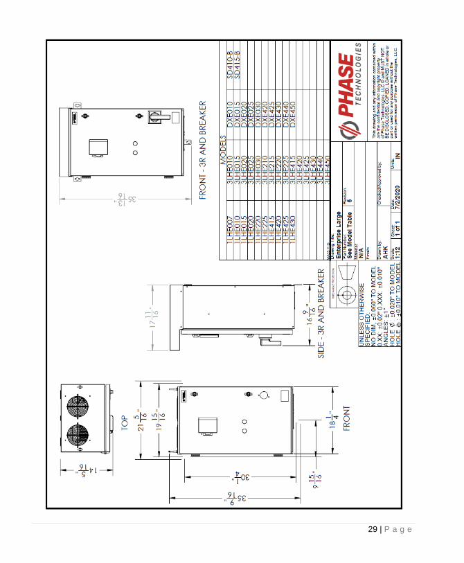
2.3 Dimensional Drawings
21 | P a g e
22 | P a g e
23 | P a g e
24 | P a g e
25 | P a g e
26 | P a g e
27 | P a g e
28 | P a g e
29 | P a g e
30 | P a g e
Optional Equipment The LH and DX drives can be configured with a variety of optional equipment. Please remember to follow all applicable NEC and local codes to ensure safety and compliance.
CAUTION: When not ordered and installed by Phase Technologies, circuit breakers or fuses, proper ground circuits, disconnects and other safety equipment and their proper installation are the responsibility of the end user.
CAUTION: The AC motor load must be connected directly to the main output terminals of the panel. Do not install relays or disconnect switches between the output terminals and the motor load.
Fuses or motor overload devices, as required by NEC and local safety codes, may be installed between the drive and the motor, however all drives are equipped with adjustable solid state motor overload protection. Surge Arrestor An optional surge arrestor is recommended in the panel on the line side of the drive to protect the input stage from damage due to voltage spikes on the utility supply. Phase Technologies offers a high quality surge protective device (SPD) as an installed option. Damage from input voltage spikes is not covered under warranty when SPDs are not installed or when an SPD not approved by Phase Technologies is installed. Contact Phase Technologies for more information.
CAUTION: The proper phase-to-ground voltage on the input lines is critical when specifying Strikesorb® SPDs. Consult with Phase Technologies before ordering this option. Improper installation can seriously damage the drive and is not covered under warranty. Output Filters Some installations may require a load reactor, dV/dt filter, or sine wave filter between the drive and the motor. Output filters are necessary when motor leads exceed 50 ft. Without filters, long leads allow reflected harmonics to create dangerous voltage spikes that can exceed the insulation rating of the motor cables and windings. Over time, these voltage spikes will degrade the insulation and result in motor faults. Output dV/dt or sine filters are standard options on most LH-DX drives. A filter reduces harmonics in the PWM output voltage, smoothing the waveforms to reduce vibration in the motor. Filters also reduce common mode currents in the motor windings that can discharge through motor bearings, causing pitting and premature motor failure.
CAUTION: Long leads between the unit and the motor with an unfiltered PWM voltage can lead to dangerous voltage rise from reflected harmonics. Very long leads, such as in deep well submersible pump applications, may require the use of a sine wave filter to remove most of the harmonics from the waveform. Consult the factory or a knowledgeable source on drive filters if your application has more than 50 feet between the converter and the motor. Molded Case Circuit Breaker (MCCB) Drives are available with an optional MCCB integrated into the panel. The breaker is equipped with an external disconnect and is service-rated.
31 | P a g e
Hand/Off/Auto (HOA) Switch with Speed Pot All LH-DX models are available with an external mounted HOA switch and speed potentiometer. When the switch is in the Hand (Manual) position, the speed pot can be used to control motor speed on the main motor output of the drive. In the Auto position, the main output is controlled by external control signals through the various analog and digital inputs to the drive. For example, if the drive were configured in constant pressure control mode, the 4-20 mA signal from the pressure transducer would control motor speed. The HOA switch in the OFF position will stop the motor on the main output of the drive. The secondary drive output, AUX POWER™, will not be affected. It is controlled by another external switch on the panel door. Auxiliary Power Supply An auxiliary power supply is available as an option on most drives in the series. The supply is rated 240/120 VAC, 0.5 Amps. Power is accessed through a second set of terminals. AUX POWER™ (1LH Series Only) Phase Technologies has designed a VFD that provides full-featured speed control of the main motor load and AUX POWER™, an independently controlled phase converter to power an entire center pivot irrigation system. The converter provides pure sinusoidal power rated 60 Hz, 460V three-phase, and is safe to power virtually any load, even sensitive electronics. The AUX POWER™ converter is available in two sizes, 18 Amps or 32 Amps. This option is available only on 1LH Series drives. Mitigating Electromagnetic Interference (EMI) Devices that utilize power switching electronics, such as VFDs, produce high frequency emissions commonly known as electromagnetic interference (EMI). These emissions can be conducted on power cables or emitted through the air. Conducted and emitted noise can sometimes interfere with radio signals or sensitive electronic equipment near the installation. The use of shielded cables and rigid metal conduit on both input and output lines between the converter and the motor is recommended to help reduce EMI. System Configuration Settings The drives are capable of operating several types of systems, including:
• Simple ON/OFF motor control from the keypad or remote switches
• Digital constant pressure water systems
• Analog constant pressure water systems
• Speed control by analog signal, either 0-5 VDC or 4-20 mA
• Combination of analog constant pressure or variable speed control by a potentiometer, selected by a manual switch
• Multiple pump control
Firmware in the drive interprets input signals and other data differently, depending upon the type of system being operated. It is therefore important to select the appropriate SYSTEM CONFIG setting either through the Programmable Parameters on the keypad. Detailed information on setting System Configuration can be found in Section 6.4.
32 | P a g e
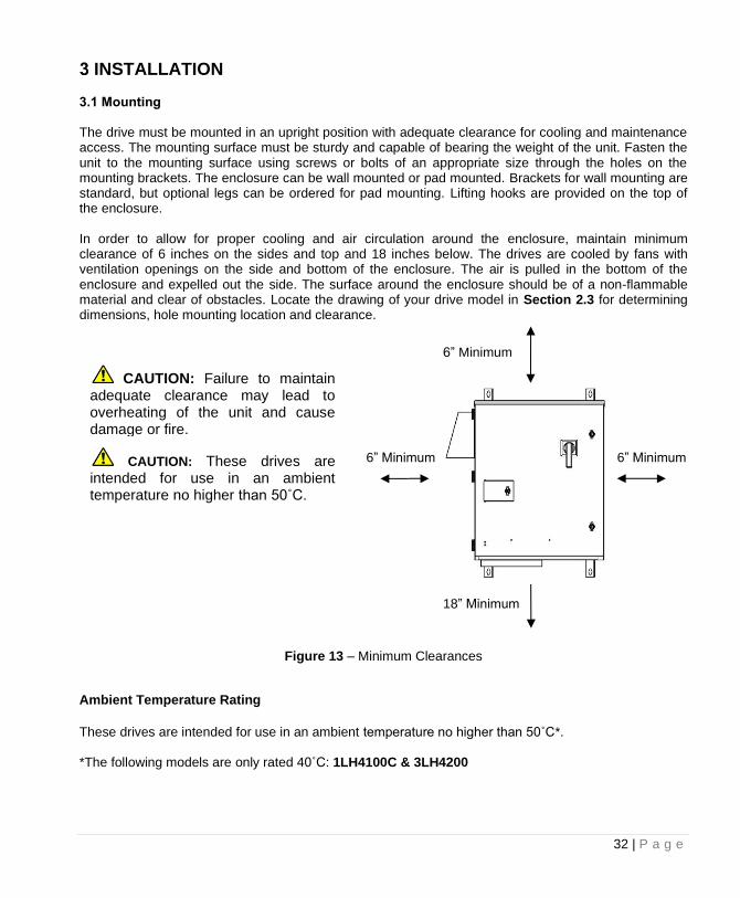
INSTALLATION 3.1 Mounting The drive must be mounted in an upright position with adequate clearance for cooling and maintenance access. The mounting surface must be sturdy and capable of bearing the weight of the unit. Fasten the unit to the mounting surface using screws or bolts of an appropriate size through the holes on the mounting brackets. The enclosure can be wall mounted or pad mounted. Brackets for wall mounting are standard, but optional legs can be ordered for pad mounting. Lifting hooks are provided on the top of the enclosure. In order to allow for proper cooling and air circulation around the enclosure, maintain minimum clearance of 6 inches on the sides and top and 18 inches below. The drives are cooled by fans with ventilation openings on the side and bottom of the enclosure. The air is pulled in the bottom of the enclosure and expelled out the side. The surface around the enclosure should be of a non-flammable material and clear of obstacles. Locate the drawing of your drive model in Section 2.3 for determining dimensions, hole mounting location and clearance.
Figure 13 – Minimum Clearances
Ambient Temperature Rating These drives are intended for use in an ambient temperature no higher than 50˚C*. *The following models are only rated 40˚C: 1LH4100C & 3LH4200
6” Minimum
6” Minimum
18” Minimum
6” Minimum
CAUTION: Failure to maintain adequate clearance may lead to overheating of the unit and cause damage or fire.
CAUTION: These drives are intended for use in an ambient temperature no higher than 50˚C.
33 | P a g e
3.2 General Wiring Considerations Installations must comply with all NEC and local electrical code requirements.
Table 10 – Power Terminal Descriptions
Terminal Name Description
L1, L2, L3 Input power terminals
U, V, W Output power terminals
T1, T2, T3 AUX POWER™ output terminals
GND Earth safety ground
Table 11 – Field Wiring Power Terminal Specifications – Input Terminals
Input Power Terminals
Model
1LH220, 1LH230, 1LH420, 1LH420C, 1LH420X, 1LH430,
1LH430C, 1LH430X, 1LH440, 1LH440C, 1LH450, 1LHS220,
1LHS230, 1LHS420, 1LHS430, 1LHS440,
1LHS450
3LHS220R, 3LHS230R, 3LHS240R, 3LHS250R, 3LHS260R,
3LH220, 3LH230, 3LH240, 3LH250, 3LH420, 3LH430, 3LH440, 3LH450, 3LH460, 3LH475,
3LH4100
1LHS240, 1LHS250, 1LH220C, 1LH220X, 1LH230C, 1LH440X, 1LH450C, 1LH450X, 1LH460,
1LH460C, 1LH460X, 1LH475,
1LH475C, 1LH4100, 1LHS460, 1LHS475, 1LHS4100
1LH475X, 1LH4100C, 1LH4125
1LHE005, 1LHE007, 1LHE010, 1LHE015, 1LHE205, 1LHE207, 1LHE210, 1LHE405, 1LHE407, 1LHE410, 1LHE420, 1LHE425
3LHE005, 3LHE007, 3LHE010, 3LHE015, 3LHE020, 3LHE205, 3LHE207, 3LHE210, 3LHE215, 3LHE220, 3LHE225, 3LHE405, 3LHE407, 3LHE410, 3LHE415, 3LHE420, 3LHE425, 3LHE430,
3LHE440 DX420, DX430, DX440, DX450, DX460, DX475,
DX4100
DXS420, DXS430, DXS440, DXS450, DXS460, DXS475,
DXS4100
1LHE015, 1LHE020, 1LHE215, 1LHE220, 1LHE225, 1LHE430, 3LHE025, 3LHE030, 3LHE450
3LH4125, 3LH4150,
3LHS4125, 3LHS4150, 3LHS260
3LH4200, 3LH4250, 3LH4300, 3LH4350, 3LH4400, 3LH4450,
3LHS4200, 3LHS4200
DXE005, DXE007, DXE010, DXE015, DXE020, DXE025, DXE030, DXE405, DXE407, DXE410, DXE415, DXE420, DXE425, DXE430, DXE440,
DXE450 DXS4125, DXS4150, DXS4200
DX4250, DX4300, DX4350, DX4450
Wire Size Torque Wire Size Torque Wire Size Torque Wire Size
Torque
2/0 AWG - 6AWG 120 in-lb 350 kcmil
275 in-lb
500 kcmil
375 in-lb 4 AWG - 18 AWG
16 in-lb 8 AWG 40 in-lb 6 AWG 4 AWG
10 – 14 AWG 35 in-lb
For a given terminal, do not use conductors larger than the maximum allowable size indicated in Table 11 above.
34 | P a g e
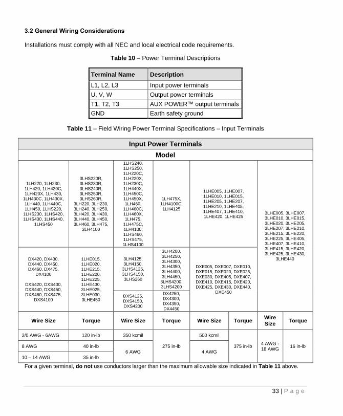
Figure 14 – Performance Series Power Terminal Location
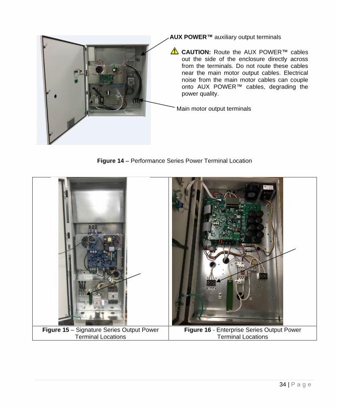
Figure 15 – Signature Series Output Power
Terminal Locations Figure 16 - Enterprise Series Output Power
Terminal Locations
AUX POWER™ auxiliary output terminals
CAUTION: Route the AUX POWER™ cables out the side of the enclosure directly across from the terminals. Do not route these cables near the main motor output cables. Electrical noise from the main motor cables can couple onto AUX POWER™ cables, degrading the power quality.
Main motor output terminals
35 | P a g e
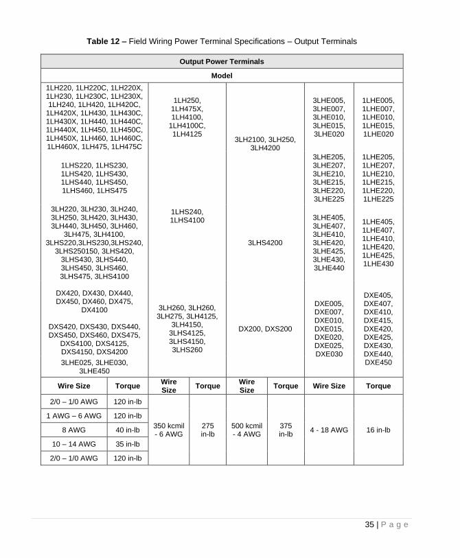
Table 12 – Field Wiring Power Terminal Specifications – Output Terminals
Output Power Terminals
Model
1LH220, 1LH220C, 1LH220X, 1LH230, 1LH230C, 1LH230X, 1LH240, 1LH420, 1LH420C,
1LH420X, 1LH430, 1LH430C, 1LH430X, 1LH440, 1LH440C, 1LH440X, 1LH450, 1LH450C, 1LH450X, 1LH460, 1LH460C, 1LH460X, 1LH475, 1LH475C
1LH250, 1LH475X, 1LH4100,
1LH4100C, 1LH4125
3LH2100, 3LH250, 3LH4200
3LHE005, 3LHE007, 3LHE010, 3LHE015, 3LHE020
1LHE005, 1LHE007, 1LHE010, 1LHE015, 1LHE020
1LHS220, 1LHS230, 1LHS420, 1LHS430, 1LHS440, 1LHS450, 1LHS460, 1LHS475
1LHS240, 1LHS4100
3LHE205, 3LHE207, 3LHE210, 3LHE215, 3LHE220, 3LHE225
1LHE205, 1LHE207, 1LHE210, 1LHE215, 1LHE220, 1LHE225
3LH220, 3LH230, 3LH240, 3LH250, 3LH420, 3LH430, 3LH440, 3LH450, 3LH460,
3LH475, 3LH4100, 3LHS220,3LHS230,3LHS240,
3LHS250150, 3LHS420, 3LHS430, 3LHS440, 3LHS450, 3LHS460, 3LHS475, 3LHS4100
3LHS4200
3LHE405, 3LHE407, 3LHE410, 3LHE420, 3LHE425, 3LHE430, 3LHE440
1LHE405, 1LHE407, 1LHE410, 1LHE420, 1LHE425, 1LHE430
DX420, DX430, DX440, DX450, DX460, DX475,
DX4100
DXS420, DXS430, DXS440, DXS450, DXS460, DXS475,
DXS4100, DXS4125, DXS4150, DXS4200
3LH260, 3LH260, 3LH275, 3LH4125,
3LH4150, 3LHS4125, 3LHS4150, 3LHS260
DX200, DXS200
DXE005, DXE007, DXE010, DXE015, DXE020, DXE025, DXE030
DXE405, DXE407, DXE410, DXE415, DXE420, DXE425, DXE430, DXE440, DXE450 3LHE025, 3LHE030,
3LHE450
Wire Size Torque Wire Size
Torque Wire Size
Torque Wire Size Torque
2/0 – 1/0 AWG 120 in-lb
350 kcmil - 6 AWG
275 in-lb
500 kcmil - 4 AWG
375 in-lb
4 - 18 AWG 16 in-lb
1 AWG – 6 AWG 120 in-lb
8 AWG 40 in-lb
10 – 14 AWG 35 in-lb
2/0 – 1/0 AWG 120 in-lb
36 | P a g e
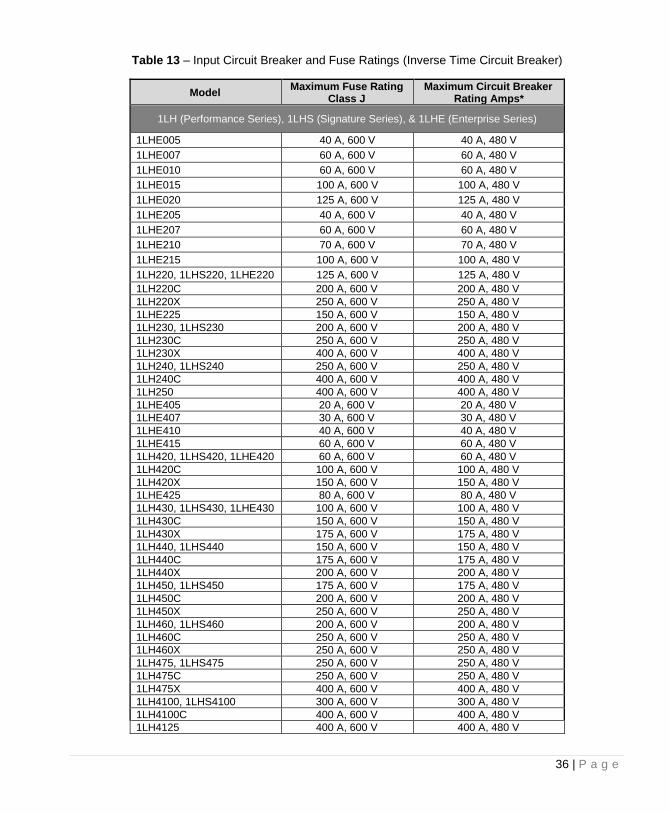
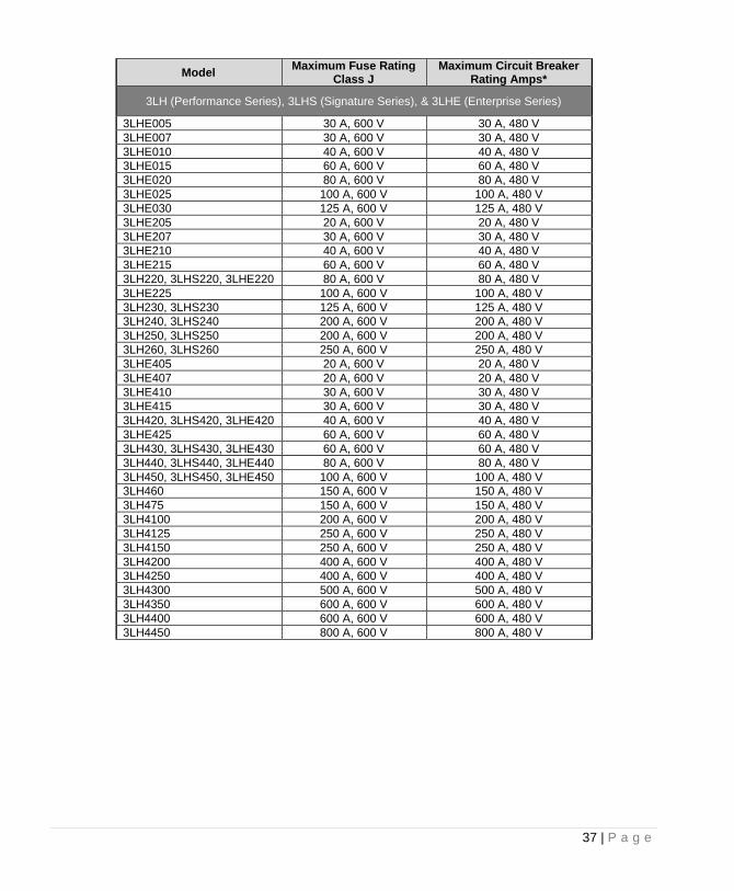
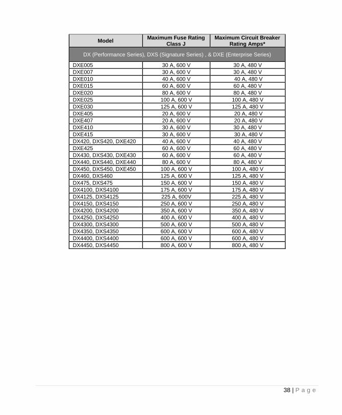
Table 13 – Input Circuit Breaker and Fuse Ratings (Inverse Time Circuit Breaker)
Model Maximum Fuse Rating
Class J Maximum Circuit Breaker
Rating Amps*
1LH (Performance Series), 1LHS (Signature Series), & 1LHE (Enterprise Series)
1LHE005 40 A, 600 V 40 A, 480 V
1LHE007 60 A, 600 V 60 A, 480 V
1LHE010 60 A, 600 V 60 A, 480 V
1LHE015 100 A, 600 V 100 A, 480 V
1LHE020 125 A, 600 V 125 A, 480 V
1LHE205 40 A, 600 V 40 A, 480 V
1LHE207 60 A, 600 V 60 A, 480 V
1LHE210 70 A, 600 V 70 A, 480 V
1LHE215 100 A, 600 V 100 A, 480 V
1LH220, 1LHS220, 1LHE220 125 A, 600 V 125 A, 480 V
1LH220C 200 A, 600 V 200 A, 480 V
1LH220X 250 A, 600 V 250 A, 480 V
1LHE225 150 A, 600 V 150 A, 480 V
1LH230, 1LHS230 200 A, 600 V 200 A, 480 V
1LH230C 250 A, 600 V 250 A, 480 V
1LH230X 400 A, 600 V 400 A, 480 V
1LH240, 1LHS240 250 A, 600 V 250 A, 480 V
1LH240C 400 A, 600 V 400 A, 480 V
1LH250 400 A, 600 V 400 A, 480 V
1LHE405 20 A, 600 V 20 A, 480 V
1LHE407 30 A, 600 V 30 A, 480 V
1LHE410 40 A, 600 V 40 A, 480 V
1LHE415 60 A, 600 V 60 A, 480 V
1LH420, 1LHS420, 1LHE420 60 A, 600 V 60 A, 480 V
1LH420C 100 A, 600 V 100 A, 480 V
1LH420X 150 A, 600 V 150 A, 480 V
1LHE425 80 A, 600 V 80 A, 480 V
1LH430, 1LHS430, 1LHE430 100 A, 600 V 100 A, 480 V
1LH430C 150 A, 600 V 150 A, 480 V
1LH430X 175 A, 600 V 175 A, 480 V
1LH440, 1LHS440 150 A, 600 V 150 A, 480 V
1LH440C 175 A, 600 V 175 A, 480 V
1LH440X 200 A, 600 V 200 A, 480 V
1LH450, 1LHS450 175 A, 600 V 175 A, 480 V
1LH450C 200 A, 600 V 200 A, 480 V
1LH450X 250 A, 600 V 250 A, 480 V
1LH460, 1LHS460 200 A, 600 V 200 A, 480 V
1LH460C 250 A, 600 V 250 A, 480 V
1LH460X 250 A, 600 V 250 A, 480 V
1LH475, 1LHS475 250 A, 600 V 250 A, 480 V
1LH475C 250 A, 600 V 250 A, 480 V
1LH475X 400 A, 600 V 400 A, 480 V
1LH4100, 1LHS4100 300 A, 600 V 300 A, 480 V
1LH4100C 400 A, 600 V 400 A, 480 V
1LH4125 400 A, 600 V 400 A, 480 V
37 | P a g e
Model Maximum Fuse Rating
Class J Maximum Circuit Breaker
Rating Amps*
3LH (Performance Series), 3LHS (Signature Series), & 3LHE (Enterprise Series)
3LHE005 30 A, 600 V 30 A, 480 V
3LHE007 30 A, 600 V 30 A, 480 V
3LHE010 40 A, 600 V 40 A, 480 V
3LHE015 60 A, 600 V 60 A, 480 V
3LHE020 80 A, 600 V 80 A, 480 V
3LHE025 100 A, 600 V 100 A, 480 V
3LHE030 125 A, 600 V 125 A, 480 V
3LHE205 20 A, 600 V 20 A, 480 V
3LHE207 30 A, 600 V 30 A, 480 V
3LHE210 40 A, 600 V 40 A, 480 V
3LHE215 60 A, 600 V 60 A, 480 V
3LH220, 3LHS220, 3LHE220 80 A, 600 V 80 A, 480 V
3LHE225 100 A, 600 V 100 A, 480 V
3LH230, 3LHS230 125 A, 600 V 125 A, 480 V
3LH240, 3LHS240 200 A, 600 V 200 A, 480 V
3LH250, 3LHS250 200 A, 600 V 200 A, 480 V
3LH260, 3LHS260 250 A, 600 V 250 A, 480 V
3LHE405 20 A, 600 V 20 A, 480 V
3LHE407 20 A, 600 V 20 A, 480 V
3LHE410 30 A, 600 V 30 A, 480 V
3LHE415 30 A, 600 V 30 A, 480 V
3LH420, 3LHS420, 3LHE420 40 A, 600 V 40 A, 480 V
3LHE425 60 A, 600 V 60 A, 480 V
3LH430, 3LHS430, 3LHE430 60 A, 600 V 60 A, 480 V
3LH440, 3LHS440, 3LHE440 80 A, 600 V 80 A, 480 V
3LH450, 3LHS450, 3LHE450 100 A, 600 V 100 A, 480 V
3LH460 150 A, 600 V 150 A, 480 V
3LH475 150 A, 600 V 150 A, 480 V
3LH4100 200 A, 600 V 200 A, 480 V
3LH4125 250 A, 600 V 250 A, 480 V
3LH4150 250 A, 600 V 250 A, 480 V
3LH4200 400 A, 600 V 400 A, 480 V
3LH4250 400 A, 600 V 400 A, 480 V
3LH4300 500 A, 600 V 500 A, 480 V
3LH4350 600 A, 600 V 600 A, 480 V
3LH4400 600 A, 600 V 600 A, 480 V
3LH4450 800 A, 600 V 800 A, 480 V
38 | P a g e
Model Maximum Fuse Rating
Class J Maximum Circuit Breaker
Rating Amps*
DX (Performance Series), DXS (Signature Series) , & DXE (Enterprise Series)
DXE005 30 A, 600 V 30 A, 480 V
DXE007 30 A, 600 V 30 A, 480 V
DXE010 40 A, 600 V 40 A, 480 V
DXE015 60 A, 600 V 60 A, 480 V
DXE020 80 A, 600 V 80 A, 480 V
DXE025 100 A, 600 V 100 A, 480 V
DXE030 125 A, 600 V 125 A, 480 V
DXE405 20 A, 600 V 20 A, 480 V
DXE407 20 A, 600 V 20 A, 480 V
DXE410 30 A, 600 V 30 A, 480 V
DXE415 30 A, 600 V 30 A, 480 V
DX420, DXS420, DXE420 40 A, 600 V 40 A, 480 V
DXE425 60 A, 600 V 60 A, 480 V
DX430, DXS430, DXE430 60 A, 600 V 60 A, 480 V
DX440, DXS440, DXE440 80 A, 600 V 80 A, 480 V
DX450, DXS450, DXE450 100 A, 600 V 100 A, 480 V
DX460, DXS460 125 A, 600 V 125 A, 480 V
DX475, DXS475 150 A, 600 V 150 A, 480 V
DX4100, DXS4100 175 A, 600 V 175 A, 480 V
DX4125, DXS4125 225 A, 600V 225 A, 480 V
DX4150, DXS4150 250 A, 600 V 250 A, 480 V
DX4200, DXS4200 350 A, 600 V 350 A, 480 V
DX4250, DXS4250 400 A, 600 V 400 A, 480 V
DX4300, DXS4300 500 A, 600 V 500 A, 480 V
DX4350, DXS4350 600 A, 600 V 600 A, 480 V
DX4400, DXS4400 600 A, 600 V 600 A, 480 V
DX4450, DXS4450 800 A, 600 V 800 A, 480 V
39 | P a g e
3.3 Installing Power Cables
CAUTION: Continuous metal conduit should be used on all power cables, both line and load side, to reduce conducted and emitted radiation of electromagnetic interference (EMI). The conduit must be securely grounded to the enclosure of the drive and the motor case. Mitigating Electromagnetic Interference (EMI) Devices that utilize power switching electronics, such as VFDs, produce high frequency emissions commonly known as electromagnetic interference (EMI). These emissions can be conducted on power cables or emitted (radiated) through the air. Conducted and emitted noise can sometimes interfere with radio signals or sensitive electronic equipment near the installation. The use of shielded cables and rigid metal conduit on the output lines between the drive and the motor is recommended to help reduce EMI. When it is not practical to use continuous metal conduit, special shielded cables can be used. The shielded cable should be constructed with symmetrical conductors and a copper or aluminum shield covered with an insulating jacket. A good shield results in lower EMI and lower motor bearing currents. Routing Power Cables Power cables should enter only through the bottom of the drive enclosure directly beneath the power terminals. Enclosures are supplied with conduit openings. Do not install line-side power cables in the same conduit or cable tray with load side power cables. Also, do not route control cables through the same conduit or cable tray as power cables. Routing Control Cables A separate conduit opening for control cables should be created through the enclosure as close as possible to the control terminals. This reduces the exposure of control cables to EMI in the enclosure. Appropriately sized conduit openings must be created with a punch. Do not use a hole saw to create openings. Exercise caution to avoid damaging drive components when making openings on the left side of the enclosure. See Figure 17 for location of openings. If the control cables must intersect the power cables, make sure they cross at right angles.
40 | P a g e
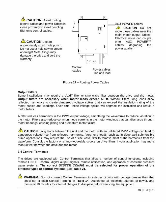
Figure 17 – Routing Power Cables
Output Filters Some installations may require a dV/dT filter or sine wave filter between the drive and the motor. Output filters are necessary when motor leads exceed 50 ft. Without filters, long leads allow reflected harmonics to create dangerous voltage spikes that can exceed the insulation rating of the motor cables and windings. Over time, these voltage spikes will degrade the insulation and result in motor failure. A filter reduces harmonics in the PWM output voltage, smoothing the waveforms to reduce vibration in the motor. Filters also reduce common mode currents in the motor windings that can discharge through motor bearings, causing pitting and premature motor failure.
CAUTION: Long leads between the unit and the motor with an unfiltered PWM voltage can lead to dangerous voltage rise from reflected harmonics. Very long leads, such as in deep well submersible pump applications, may require the use of a sine wave filter to remove most of the harmonics from the waveform. Consult the factory or a knowledgeable source on drive filters if your application has more than 50 feet between the drive and the motor. 3.4 Control Terminals The drives are equipped with Control Terminals that allow a number of control functions, including remote ON/OFF control, digital output signals, remote notification, and operation of constant pressure water systems. The correct SYSTEM CONFIG must be selected for proper operation of the different types of control systems! See Table 21.
WARNING: Do not connect Control Terminals to external circuits with voltage greater than that specified for each Control Terminal in Table 14. Disconnect all incoming sources of power, and then wait 10 minutes for internal charges to dissipate before servicing the equipment.
CAUTION: Avoid routing
control cables and power cables in close proximity to avoid coupling EMI onto control cables.
12” min
CAUTION Use an
appropriately sized hole punch. Do not use a hole saw to create openings! Metal filings may damage the drive and void the warranty.
AUX POWER cables
CAUTION Do not route these cables near the main motor output cables. Electrical noise can couple onto AUX POWER™ cables, degrading the power quality.
Control cables Power cables,
line and load
41 | P a g e
CAUTION: The AUX1, AUX2, AUX3 and AUX4 terminals are galvanically isolated, with approximately 5 V potential between them. DO NOT apply a voltage to the terminals. Use dry contacts only.
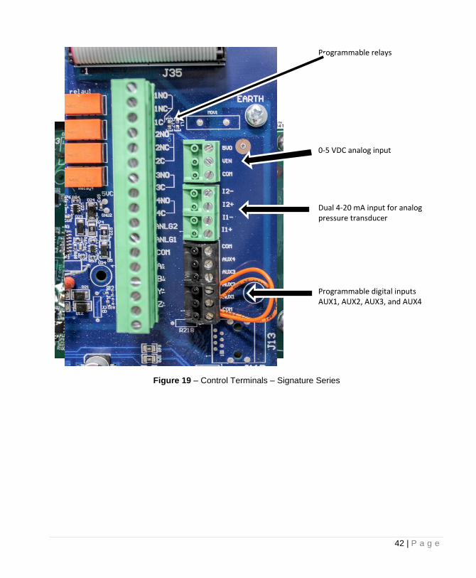
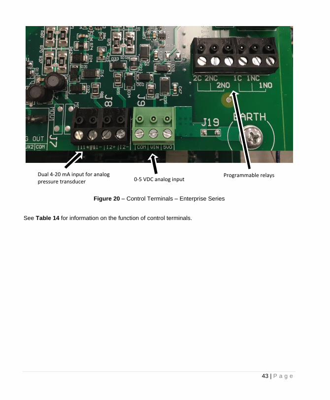
Customer terminals are located on the Control Board of each drive. Figure 18 – Figure 20 show where the control terminals are located on the Control Board for each system.
Figure 18 – Control Terminals – Performance Series
Dual 4-20 mA input for analog pressure transducer
Programmable digital inputs AUX1, AUX2, AUX3, and AUX4
0-5 VDC analog input
Programmable relays
42 | P a g e
Figure 19 – Control Terminals – Signature Series
Dual 4-20 mA input for analog pressure transducer
0-5 VDC analog input
Programmable relays
Programmable digital inputs AUX1, AUX2, AUX3, and AUX4
43 | P a g e
Figure 20 – Control Terminals – Enterprise Series
See Table 14 for information on the function of control terminals.
Programmable relays Dual 4-20 mA input for analog pressure transducer 0-5 VDC analog input
44 | P a g e
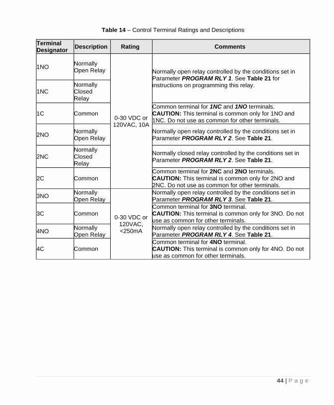
Table 14 – Control Terminal Ratings and Descriptions
Terminal Designator Description Rating Comments
1NO Normally Open Relay
0-30 VDC or 120VAC, 10A
Normally open relay controlled by the conditions set in Parameter PROGRAM RLY 1. See Table 21 for instructions on programming this relay.
1NC Normally Closed Relay
1C Common Common terminal for 1NC and 1NO terminals. CAUTION: This terminal is common only for 1NO and 1NC. Do not use as common for other terminals.
2NO Normally Open Relay
Normally open relay controlled by the conditions set in Parameter PROGRAM RLY 2. See Table 21.
2NC Normally Closed Relay
Normally closed relay controlled by the conditions set in Parameter PROGRAM RLY 2. See Table 21.
2C Common Common terminal for 2NC and 2NO terminals. CAUTION: This terminal is common only for 2NO and 2NC. Do not use as common for other terminals.
3NO Normally Open Relay
0-30 VDC or 120VAC, <250mA
Normally open relay controlled by the conditions set in Parameter PROGRAM RLY 3. See Table 21.
3C Common Common terminal for 3NO terminal. CAUTION: This terminal is common only for 3NO. Do not use as common for other terminals.
4NO Normally Open Relay
Normally open relay controlled by the conditions set in Parameter PROGRAM RLY 4. See Table 21.
4C Common Common terminal for 4NO terminal. CAUTION: This terminal is common only for 4NO. Do not use as common for other terminals.
45 | P a g e
Table 14 – Continued
Terminal Designator Description Rating Comments
AUX1 Auxiliary 1
< 5 Volts galvanically isolated
Programmable digital input. Commonly used for RUN/STOP command. See Table 21.
AUX2 Auxiliary 2
AUX3 Auxiliary 3
AUX4 Auxiliary 4
COM Common for all terminals except programmable relays.
I_1 in + 4-20 mA positive
4-20 mA
Analog transducer connection for analog constant pressure or proportional motor speed control from a current source. Refer to Table 21 or Section 6.4 for details. See Figure 21 for a connection diagram to control terminals.
I_1 in – 4-20 mA negative
I_2 in + 4-20 mA positive
I_2 in – 4-20 mA negative
5 VO 0-5 VDC output
0-5 VDC
5 VDC supply to provide power to a potentiometer. Refer to Table 21 or Section 6.4 for details. See Figure 22 for a connection diagram to control terminals.
V In 0-5 VDC input
Analog input for motor speed control for 0-5 VDC. Speed is relative to scale of signal from 0 Hz to Maximum Frequency as set in Adjustable Parameter menu (factory default 60 Hz). Connect the wiper terminal of a potentiometer to this terminal. See Figure 22 for a connection diagram to control terminals.
COM Common Common for 0-5 VDC. See Figure 21 - Figure 23 for a connection diagram to control terminals.
46 | P a g e
4-20 mA Analog Input Motor speed can be controlled with 4-20 mA analog input through control terminals I_1 and I_2. A 4-20 mA pressure transducer is also commonly used for constant pressure control through these terminals. 4-20 mA Transducer Connection: 1. Using the keypad, set the value of parameter SYSTEM CONFIG to 2, 3, 4 or 6 depending on the
desired mode of operation. See Table 21 – Interface Parameters, and Section 6.4 for details. 2. Connect the positive lead of the transducer to terminal I_1+ or I_2+ 3. Connect the negative lead of the transducer to terminal I_1- or I_2- 4. AUX terminals must be closed to run. 4-20 mA Transducer with External Source Connection: 1. Using the keypad, set the value of parameter SYSTEM CONFIG to 2, 3, 4 or 6 depending on the
desired mode of operation. See Table 21 – Interface Parameters, and Section 6.4 for details. 2. Connect the positive lead of the transducer to terminal I_1+ or I_2+ 3. Connect the negative lead of the transducer to COM 4. AUX terminals must be closed to run.
CAUTION: A 4-20 mA transducer with the parameter SYSTEM CONFIG set at 6 results in linear speed control of the motor based on the analog signal from the transducer. This setting will not provide control of a constant pressure water system. For constant pressure control with 4-20mA transducer, refer to Section 6.4, System Configuration, and Section 7 Constant Pressure Systems, for more information.
+
4-20 mA
Transducer
-
I_1+ I_1-
a. 4-20 mA Transducer Connection b. 4-20 mA Transducer with External
Source
Figure 21 – Control Terminal Connection Diagram for 4-20 mA Control
47 | P a g e
0-5 VDC Analog Input Motor speed can be controlled with a 0-5 VDC signal through control terminals 5 VO, 5 VI and COM. When using a speed potentiometer (variable resistor) the drive provides a DC source voltage. Speed control can also be accomplished with an external DC voltage signal. Potentiometer connection: 1. Using the keypad, set the value of parameter SYSTEM CONFIG to 5 or 7. Refer to Table 21 –
Interface Parameters, Interface Parameters, or Section 6.4, System Configuration, for details. 2. Connect the negative lead of the potentiometer to COM 3. Connect the wiper terminal of the potentiometer to V IN 4. Connect the positive lead of the potentiometer to 5 VO 5. AUX terminals must be closed to run External DC voltage signal: 1. Set parameter SYSTEM CONFIG to 5. 2. Connect negative lead to COM 3. Connect positive lead to V IN
CAUTION: The resistance value of the transducer must be from 5,000 ohms to 20,000 ohms. Resistance below 5,000 ohms will produce a high current in the circuit and may damage components in the circuit.
a. Potentiometer Connection Diagram b. External DC Voltage Connection
Diagram
Figure 22 – Control Terminal Connection Diagram for 0-5 VDC Control
48 | P a g e
Analog Constant Pressure with Potentiometer and HOA Switch The drives can be configured with a HOA switch that allows the user to either turn the motor off, control motor speed with a potentiometer or operate in constant pressure mode. Access to the keypad is not required to operate in this mode. 1. Using the keypad, set the value of parameter SYSTEM CONFIG to 7. See Table 21 – Interface
Parameters, for details. 2. Connect the potentiometer and 4-20 mA transducer as in Figure 21 and Figure 22. 3. Connect a double pole, triple throw HOA switch to AUX1 and AUX3 as depicted in Figure 23. 4. Using the keypad, set the drive to operate in AUTO mode. 5. AUX2 and AUX4 must be closed to run. The mechanical HOA switch allows the user to select between OFF, manual speed control with the potentiometer or analog constant pressure. In the H (Hand/Manual) position, motor speed is controlled by the potentiometer. In the O (Off) position the motor will stop. In the A (Auto) position motor speed will be controlled by constant pressure parameters.
Figure 23 – Connections for Analog Constant Pressure with Potentiometer and HOA Switch
CAUTION: When the HOA switch is in the manual (H) position, the drive will ignore the status of AUX2 Control Terminal.
5 VOCOM AUX1AUX3 I in+ I in- V IN COM
0-5VDC
+ -
4-20 mA
Transducer
-+
H AO
Double pole, triple
throw HOA switch
49 | P a g e
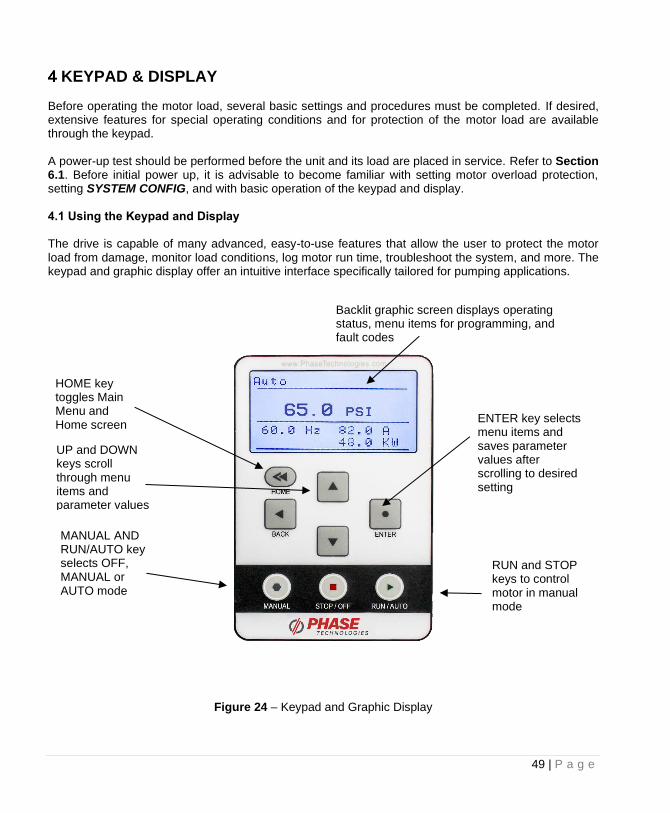
KEYPAD & DISPLAY Before operating the motor load, several basic settings and procedures must be completed. If desired, extensive features for special operating conditions and for protection of the motor load are available through the keypad. A power-up test should be performed before the unit and its load are placed in service. Refer to Section 6.1. Before initial power up, it is advisable to become familiar with setting motor overload protection, setting SYSTEM CONFIG, and with basic operation of the keypad and display. 4.1 Using the Keypad and Display The drive is capable of many advanced, easy-to-use features that allow the user to protect the motor load from damage, monitor load conditions, log motor run time, troubleshoot the system, and more. The keypad and graphic display offer an intuitive interface specifically tailored for pumping applications.
Figure 24 – Keypad and Graphic Display
Backlit graphic screen displays operating status, menu items for programming, and fault codes
MANUAL AND RUN/AUTO key selects OFF, MANUAL or AUTO mode
HOME key toggles Main Menu and Home screen
RUN and STOP keys to control motor in manual mode
ENTER key selects menu items and saves parameter values after scrolling to desired setting
UP and DOWN keys scroll through menu items and parameter values
50 | P a g e
Display Modes After two minutes of keypad inactivity, the display will revert to the default display mode. Information on the display will vary based on the operating mode of the drive. When operating in AUTO mode with the factory default SYSTEM CONFIG set to 0, the display will indicate output kilowatts (kW), output amps (A), output frequency (Hz) and the status of the AUX1 and AUX2 inputs. Password Protecting the Keypad The keypad can be set up with a password to prevent unauthorized changes in adjustable parameters. The parameter PASSWORD SETUP (Table 21 – Interface Parameters) is used to protect the keypad. When this parameter is set to 0 the keypad is not protected. To password protect the keypad, enter a password consisting of a number between 1 and 99. Contact customer service at 605-343-7934 if you lose or forget the password. Keypad Display Messages Several messages will appear on the display when the unit is initially energized. When the unit has completed its start-up routine, the default display indicating the status of the OFF, AUTO, MAN mode will appear. Start-up display messages are detailed in Table 15 below.
Table 15 – Display of Operating Modes
MODE DESCRIPTION
AUTO
The factory default operating mode is OFF. The adjustable parameter, ENABLE RESTARTS, must be set to 1 to allow automatic re-starts. See Table 19 – Operating Parameters, for details.
CAUTION: In AUTO mode, the motor load will automatically run if both AUX1 and AUX2 remote switches are closed. Open AUX1 or AUX2 to stop the motor or push
STOP/OFF key. CAUTION: By default, AUX1 and AUX2 are programmed to be always ON. See AUX1 SELECT and AUX2 SELECT to change this setting.
MANUAL
Activate MANUAL mode by pushing the MANUAL key until MANUAL appears on top left of the display. In MANUAL mode the motor load is controlled by using the RUN and STOP keys, which will override all external control signals. Manual control of the drive through the keypad can be disabled through the parameter DISABLE MANUAL. See Table 21 – Interface Parameters, for details.
CAUTION: Operating the system in MANUAL mode on the keypad overrides signals from all external controls, including pressures switches. Operating the system in this mode may lead to dangerous operating conditions such as extreme pressure in closed plumbing systems.
OFF
The factory default operating mode is OFF. The adjustable parameter, ENABLE RESTARTS, must be set to 1 to allow automatic re-starts. To exit AUTO mode, press the STOP/OFF key until OFF appears on top left of the display. If the motor us running, it will stop. To restart the motor, revert to either AUTO mode or MANUAL mode. Certain faults can also be cleared by pressing the up and down arrow keys at the same time and holding for one second.
51 | P a g e
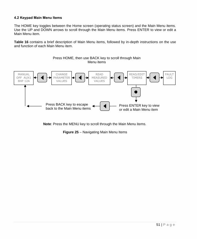
4.2 Keypad Main Menu Items The HOME key toggles between the Home screen (operating status screen) and the Main Menu items. Use the UP and DOWN arrows to scroll through the Main Menu items. Press ENTER to view or edit a Main Menu item. Table 16 contains a brief description of Main Menu items, followed by in-depth instructions on the use and function of each Main Menu item.
Figure 25 – Navigating Main Menu Items
CHANGE
PARAMETER
VALUES
MANUAL
OFF AUX1
8HP 12A
READ
MEASURED
VALUES
READ/EDIT
TIMERS
FAULT
LOG
Press HOME, then use BACK key to scroll through Main Menu items
Press ENTER key to view or edit a Main Menu item
Press BACK key to escape back to the Main Menu items
Note: Press the MENU key to scroll through the Main Menu items.
52 | P a g e
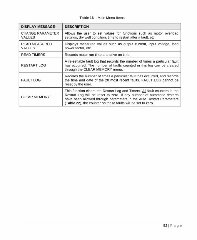
Table 16 – Main Menu Items
DISPLAY MESSAGE DESCRIPTION
CHANGE PARAMETER VALUES
Allows the user to set values for functions such as motor overload settings, dry well condition, time to restart after a fault, etc.
READ MEASURED VALUES
Displays measured values such as output current, input voltage, load power factor, etc.
READ TIMERS Records motor run time and drive on time.
RESTART LOG A re-settable fault log that records the number of times a particular fault has occurred. The number of faults counted in this log can be cleared through the CLEAR MEMORY menu.
FAULT LOG Records the number of times a particular fault has occurred, and records the time and date of the 20 most recent faults. FAULT LOG cannot be reset by the user.
CLEAR MEMORY
This function clears the Restart Log and Timers. All fault counters in the Restart Log will be reset to zero. If any number of automatic restarts have been allowed through parameters in the Auto Restart Parameters (Table 22), the counter on these faults will be set to zero.
53 | P a g e
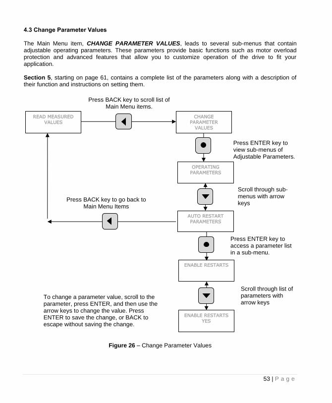
4.3 Change Parameter Values The Main Menu item, CHANGE PARAMETER VALUES, leads to several sub-menus that contain adjustable operating parameters. These parameters provide basic functions such as motor overload protection and advanced features that allow you to customize operation of the drive to fit your application. Section 5, starting on page 61, contains a complete list of the parameters along with a description of their function and instructions on setting them.
Figure 26 – Change Parameter Values
READ MEASURED
VALUES
CHANGE PARAMETER
VALUES
Press BACK key to scroll list of Main Menu items.
Press ENTER key to view sub-menus of Adjustable Parameters.
OPERATING
PARAMETERS
AUTO RESTART
PARAMETERS
Scroll through sub-menus with arrow keys
Press BACK key to go back to Main Menu Items
ENABLE RESTARTS
Press ENTER key to access a parameter list in a sub-menu.
Scroll through list of parameters with arrow keys
To change a parameter value, scroll to the parameter, press ENTER, and then use the arrow keys to change the value. Press ENTER to save the change, or BACK to escape without saving the change.
ENABLE RESTARTS
YES
54 | P a g e
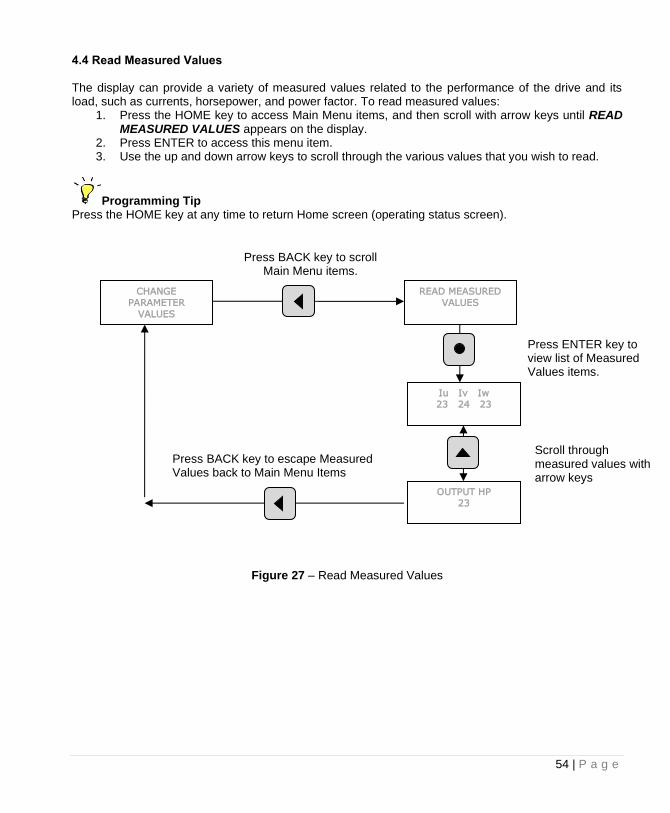
4.4 Read Measured Values The display can provide a variety of measured values related to the performance of the drive and its load, such as currents, horsepower, and power factor. To read measured values:
1. Press the HOME key to access Main Menu items, and then scroll with arrow keys until READ MEASURED VALUES appears on the display.
2. Press ENTER to access this menu item. 3. Use the up and down arrow keys to scroll through the various values that you wish to read.
Programming Tip Press the HOME key at any time to return Home screen (operating status screen).
Figure 27 – Read Measured Values
CHANGE
PARAMETER
VALUES
READ MEASURED
VALUES
Press BACK key to scroll Main Menu items.
Press ENTER key to view list of Measured Values items.
Iu Iv Iw
23 24 23
OUTPUT HP
23
Scroll through measured values with arrow keys
Press BACK key to escape Measured Values back to Main Menu Items
55 | P a g e
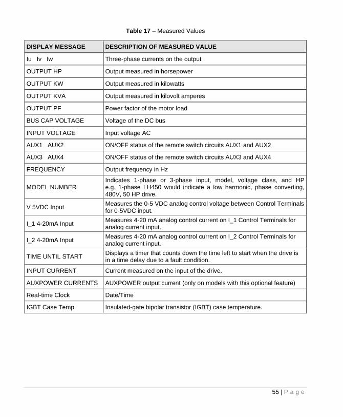
Table 17 – Measured Values
DISPLAY MESSAGE DESCRIPTION OF MEASURED VALUE
Iu Iv Iw Three-phase currents on the output
OUTPUT HP Output measured in horsepower
OUTPUT KW Output measured in kilowatts
OUTPUT KVA Output measured in kilovolt amperes
OUTPUT PF Power factor of the motor load
BUS CAP VOLTAGE Voltage of the DC bus
INPUT VOLTAGE Input voltage AC
AUX1 AUX2 ON/OFF status of the remote switch circuits AUX1 and AUX2
AUX3 AUX4 ON/OFF status of the remote switch circuits AUX3 and AUX4
FREQUENCY Output frequency in Hz
MODEL NUMBER Indicates 1-phase or 3-phase input, model, voltage class, and HP e.g. 1-phase LH450 would indicate a low harmonic, phase converting, 480V, 50 HP drive.
V 5VDC Input Measures the 0-5 VDC analog control voltage between Control Terminals for 0-5VDC input.
I_1 4-20mA Input Measures 4-20 mA analog control current on I_1 Control Terminals for analog current input.
I_2 4-20mA Input Measures 4-20 mA analog control current on I_2 Control Terminals for analog current input.
TIME UNTIL START Displays a timer that counts down the time left to start when the drive is in a time delay due to a fault condition.
INPUT CURRENT Current measured on the input of the drive.
AUXPOWER CURRENTS AUXPOWER output current (only on models with this optional feature)
Real-time Clock Date/Time
IGBT Case Temp Insulated-gate bipolar transistor (IGBT) case temperature.
56 | P a g e
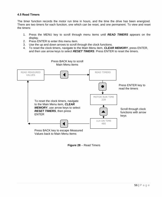
4.5 Read Timers The timer function records the motor run time in hours, and the time the drive has been energized. There are two timers for each function, one which can be reset, and one permanent. To view and reset the timers:
1. Press the MENU key to scroll through menu items until READ TIMERS appears on the display.
2. Press ENTER to enter this menu item. 3. Use the up and down arrows to scroll through the clock functions. 4. To reset the clock timers, navigate to the Main Menu item, CLEAR MEMORY, press ENTER,
and then use arrow keys to select RESET TIMERS. Press ENTER to reset the timers.
Figure 28 – Read Timers
READ MEASURED
VALUES
READ TIMERS
Press ENTER key to read the timers
MOTOR RUN TIME
239
1LH ON TIME
480
Scroll through clock functions with arrow keys
Press BACK key to escape Measured Values back to Main Menu Items
To reset the clock timers, navigate to the Main Menu item, CLEAR MEMORY, use arrow keys to select RESET TIMERS, then press ENTER
Press BACK key to scroll Main Menu items
57 | P a g e
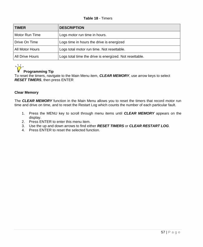
Table 18 - Timers
TIMER DESCRIPTION
Motor Run Time Logs motor run time in hours.
Drive On Time Logs time in hours the drive is energized
All Motor Hours Logs total motor run time. Not resettable.
All Drive Hours Logs total time the drive is energized. Not resettable.
Programming Tip To reset the timers, navigate to the Main Menu item, CLEAR MEMORY, use arrow keys to select RESET TIMERS, then press ENTER Clear Memory The CLEAR MEMORY function in the Main Menu allows you to reset the timers that record motor run time and drive on time, and to reset the Restart Log which counts the number of each particular fault.
1. Press the MENU key to scroll through menu items until CLEAR MEMORY appears on the display.
2. Press ENTER to enter this menu item. 3. Use the up and down arrows to find either RESET TIMERS or CLEAR RESTART LOG. 4. Press ENTER to reset the selected function.
58 | P a g e
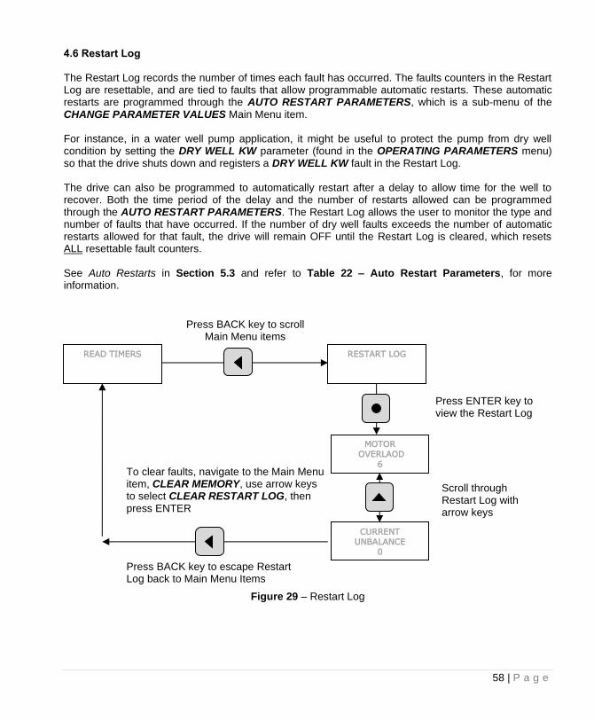
4.6 Restart Log The Restart Log records the number of times each fault has occurred. The faults counters in the Restart Log are resettable, and are tied to faults that allow programmable automatic restarts. These automatic restarts are programmed through the AUTO RESTART PARAMETERS, which is a sub-menu of the CHANGE PARAMETER VALUES Main Menu item. For instance, in a water well pump application, it might be useful to protect the pump from dry well condition by setting the DRY WELL KW parameter (found in the OPERATING PARAMETERS menu) so that the drive shuts down and registers a DRY WELL KW fault in the Restart Log. The drive can also be programmed to automatically restart after a delay to allow time for the well to recover. Both the time period of the delay and the number of restarts allowed can be programmed through the AUTO RESTART PARAMETERS. The Restart Log allows the user to monitor the type and number of faults that have occurred. If the number of dry well faults exceeds the number of automatic restarts allowed for that fault, the drive will remain OFF until the Restart Log is cleared, which resets ALL resettable fault counters. See Auto Restarts in Section 5.3 and refer to Table 22 – Auto Restart Parameters, for more information.
Figure 29 – Restart Log
READ TIMERS RESTART LOG
Press ENTER key to view the Restart Log
MOTOR
OVERLAOD
6
CURRENT
UNBALANCE
0
Scroll through Restart Log with arrow keys
Press BACK key to escape Restart Log back to Main Menu Items
To clear faults, navigate to the Main Menu item, CLEAR MEMORY, use arrow keys to select CLEAR RESTART LOG, then press ENTER
Press BACK key to scroll Main Menu items
59 | P a g e
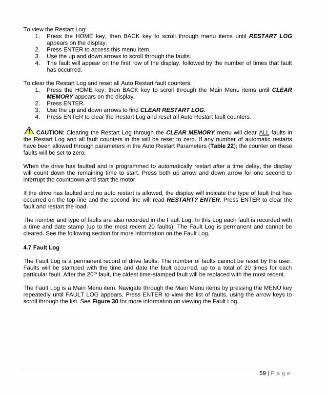
To view the Restart Log: 1. Press the HOME key, then BACK key to scroll through menu items until RESTART LOG
appears on the display. 2. Press ENTER to access this menu item. 3. Use the up and down arrows to scroll through the faults. 4. The fault will appear on the first row of the display, followed by the number of times that fault
has occurred. To clear the Restart Log and reset all Auto Restart fault counters:
1. Press the HOME key, then BACK key to scroll through the Main Menu items until CLEAR MEMORY appears on the display.
2. Press ENTER. 3. Use the up and down arrows to find CLEAR RESTART LOG. 4. Press ENTER to clear the Restart Log and reset all Auto Restart fault counters.
CAUTION: Clearing the Restart Log through the CLEAR MEMORY menu will clear ALL faults in the Restart Log and all fault counters in the will be reset to zero. If any number of automatic restarts have been allowed through parameters in the Auto Restart Parameters (Table 22); the counter on these faults will be set to zero. When the drive has faulted and is programmed to automatically restart after a time delay, the display will count down the remaining time to start. Press both up arrow and down arrow for one second to interrupt the countdown and start the motor. If the drive has faulted and no auto restart is allowed, the display will indicate the type of fault that has occurred on the top line and the second line will read RESTART? ENTER. Press ENTER to clear the fault and restart the load. The number and type of faults are also recorded in the Fault Log. In this Log each fault is recorded with a time and date stamp (up to the most recent 20 faults). The Fault Log is permanent and cannot be cleared. See the following section for more information on the Fault Log.
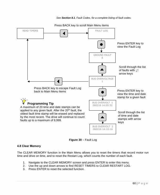
4.7 Fault Log The Fault Log is a permanent record of drive faults. The number of faults cannot be reset by the user. Faults will be stamped with the time and date the fault occurred, up to a total of 20 times for each particular fault. After the 20th fault, the oldest time-stamped fault will be replaced with the most recent. The Fault Log is a Main Menu item. Navigate through the Main Menu items by pressing the MENU key repeatedly until FAULT LOG appears. Press ENTER to view the list of faults, using the arrow keys to scroll through the list. See Figure 30 for more information on viewing the Fault Log.
60 | P a g e
Figure 30 – Fault Log
4.8 Clear Memory The CLEAR MEMORY function in the Main Menu allows you to reset the timers that record motor run time and drive on time, and to reset the Restart Log, which counts the number of each fault.
1. Navigate to the CLEAR MEMORY screen and press ENTER to enter this menu. 2. Use the up and down arrows to find RESET TIMERS to CLEAR RESTART LOG. 3. Press ENTER to reset the selected function.
READ TIMERS FAULT LOG
Press ENTER key to view the Fault Log
GROUND FAULT
6
BUS OVERVOLTAGE
1
Scroll through the list of faults with ↓↑ arrow keys
Press BACK key to escape Fault Log back to Main Menu Items
BUS OVERVOLT 1
060216 14:05:32
Press ENTER key to view the time and date stamp for a given fault
BUS OVERVOLT 2
060216 14:10:16
Scroll through the list of time and date stamps with arrow keys
Programming Tip A maximum of 20 time and date stamps can be applied to any given fault. After the 20th fault, the oldest fault time stamp will be erased and replaced by the most recent. The drive will continue to count faults up to a maximum of 9,999.
Press BACK key to scroll Main Menu items
See Section 8.1, Fault Codes, for a complete listing of fault codes.
61 | P a g e
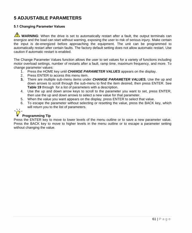
ADJUSTABLE PARAMETERS 5.1 Changing Parameter Values
WARNING: When the drive is set to automatically restart after a fault, the output terminals can energize and the load can start without warning, exposing the user to risk of serious injury. Make certain the input is de-energized before approaching the equipment. The unit can be programmed to automatically restart after certain faults. The factory default setting does not allow automatic restart. Use caution if automatic restart is enabled. The Change Parameter Values function allows the user to set values for a variety of functions including motor overload settings, number of restarts after a fault, ramp time, maximum frequency, and more. To change parameter values:
1. Press the HOME key until CHANGE PARAMETER VALUES appears on the display. 2. Press ENTER to access this menu item. 3. There are multiple sub-menu items under CHANGE PARAMETER VALUES. Use the up and
down arrows to scroll through the sub-menu to find the item desired, then press ENTER. See Table 19 through for a list of parameters with a description.
4. Use the up and down arrow keys to scroll to the parameter you want to set, press ENTER, then use the up and down arrows to select a new value for that parameter.
5. When the value you want appears on the display, press ENTER to select that value. 6. To escape the parameter without selecting or resetting the value, press the BACK key, which
will return you to the list of parameters.
Programming Tip Press the ENTER key to move to lower levels of the menu outline or to save a new parameter value. Press the BACK key to move to higher levels in the menu outline or to escape a parameter setting without changing the value.
62 | P a g e
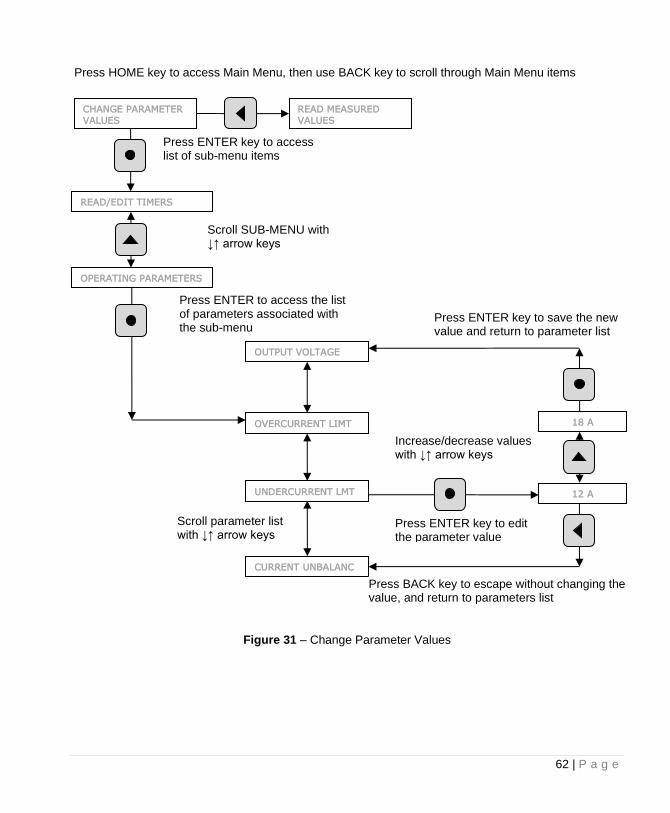
Figure 31 – Change Parameter Values
CHANGE PARAMETER
VALUES
READ/EDIT TIMERS
OPERATING PARAMETERS
Press ENTER key to access list of sub-menu items
18 A
READ MEASURED
VALUES
Press HOME key to access Main Menu, then use BACK key to scroll through Main Menu items
Scroll SUB-MENU with ↓↑ arrow keys
12 A UNDERCURRENT LMT
CURRENT UNBALANC
Press ENTER key to edit the parameter value
Increase/decrease values with ↓↑ arrow keys
Press ENTER key to save the new value and return to parameter list
Press BACK key to escape without changing the value, and return to parameters list
Press ENTER to access the list of parameters associated with the sub-menu
OVERCURRENT LIMT
OUTPUT VOLTAGE
Scroll parameter list with ↓↑ arrow keys
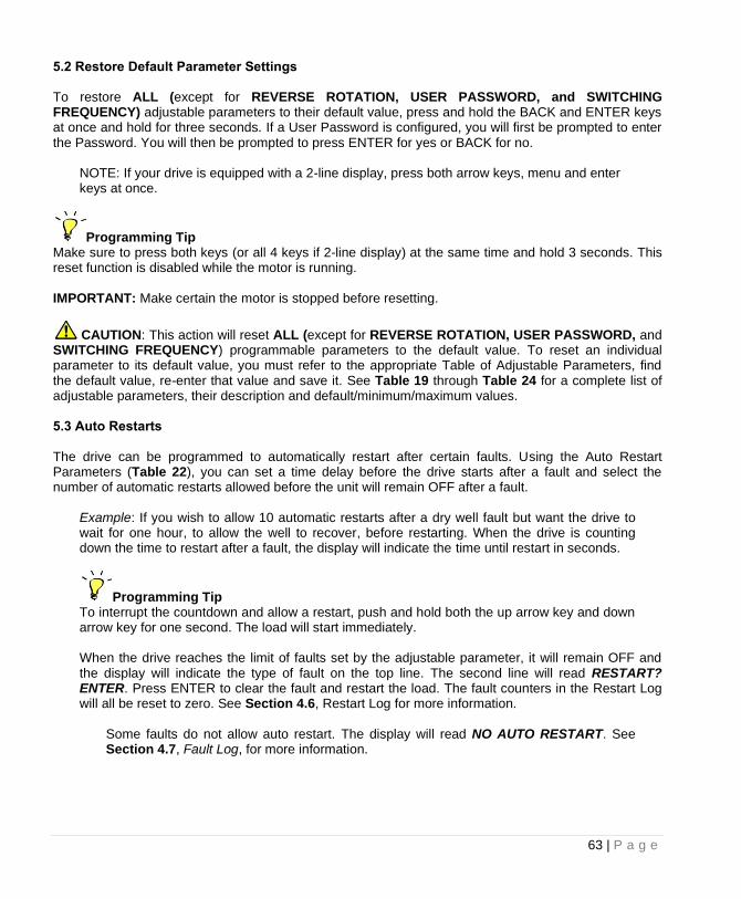
63 | P a g e
5.2 Restore Default Parameter Settings To restore ALL (except for REVERSE ROTATION, USER PASSWORD, and SWITCHING FREQUENCY) adjustable parameters to their default value, press and hold the BACK and ENTER keys at once and hold for three seconds. If a User Password is configured, you will first be prompted to enter the Password. You will then be prompted to press ENTER for yes or BACK for no.
NOTE: If your drive is equipped with a 2-line display, press both arrow keys, menu and enter keys at once.
Programming Tip Make sure to press both keys (or all 4 keys if 2-line display) at the same time and hold 3 seconds. This reset function is disabled while the motor is running. IMPORTANT: Make certain the motor is stopped before resetting.
CAUTION: This action will reset ALL (except for REVERSE ROTATION, USER PASSWORD, and SWITCHING FREQUENCY) programmable parameters to the default value. To reset an individual parameter to its default value, you must refer to the appropriate Table of Adjustable Parameters, find the default value, re-enter that value and save it. See Table 19 through Table 24 for a complete list of adjustable parameters, their description and default/minimum/maximum values. 5.3 Auto Restarts The drive can be programmed to automatically restart after certain faults. Using the Auto Restart Parameters (Table 22), you can set a time delay before the drive starts after a fault and select the number of automatic restarts allowed before the unit will remain OFF after a fault.
Example: If you wish to allow 10 automatic restarts after a dry well fault but want the drive to wait for one hour, to allow the well to recover, before restarting. When the drive is counting down the time to restart after a fault, the display will indicate the time until restart in seconds.
Programming Tip To interrupt the countdown and allow a restart, push and hold both the up arrow key and down arrow key for one second. The load will start immediately.
When the drive reaches the limit of faults set by the adjustable parameter, it will remain OFF and the display will indicate the type of fault on the top line. The second line will read RESTART? ENTER. Press ENTER to clear the fault and restart the load. The fault counters in the Restart Log will all be reset to zero. See Section 4.6, Restart Log for more information.
Some faults do not allow auto restart. The display will read NO AUTO RESTART. See Section 4.7, Fault Log, for more information.
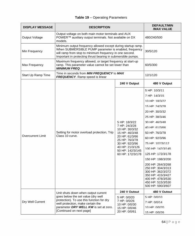
64 | P a g e
Table 19 – Operating Parameters
DISPLAY MESSAGE DESCRIPTION DEFAULT/MIN /MAX VALUE
Output Voltage Output voltage on both main motor terminals and AUX POWER™ auxiliary output terminals. Not available on DX models.
480/240/500
Min Frequency
Minimum output frequency allowed except during startup ramp. When SUBMERSIBLE PUMP parameter is enabled, frequency will ramp from stop to minimum frequency in one second. Important in protecting thrust bearing in submersible pumps.
30/5/120
Max Frequency Maximum frequency allowed, or target frequency at start-up ramp. This parameter value cannot be set lower than MINIMUM FREQ.
60/5/300
Start Up Ramp Time Time in seconds from MIN FREQUENCY to MAX FREQUENCY. Ramp speed is linear
12/1/120
Overcurrent Limit
Setting for motor overload protection, Trip Class 10 curve.
240 V Output 480 V Output
5 HP: 18/3/22 7 HP: 24/3/28 10 HP: 30/3/32 15 HP: 46/3/48 20 HP: 61/3/66 25 HP: 76/3/78 30 HP: 92/3/96 40 HP: 21/3/126 50 HP: 142/3/145 60 HP: 172/3/178
5 HP: 10/3/11
7 HP: 14/3/15
10 HP: 18/3/22
15 HP: 24/3/28
20 HP: 30/3/32
25 HP: 38/3/46
30 HP: 46/3/48
40 HP: 61/3/66
50 HP: 76/3/78
60 HP: 92/3/96
75 HP: 107/3/112
100 HP: 142/3/145
125 HP: 172/3/178
150 HP: 198/3/200
200 HP: 264/3/268 250 HP: 304/3/313 300 HP: 362/3/372 350 HP: 415/3/427 400 HP: 478/3/530 450 HP: 515/3/530 500 HP: 590/3/607
Dry Well Current
Unit shuts down when output current goes below the set value (dry well protection). To use this function for dry well protection, make certain the parameter DRY WELL KW is set at zero. [Continued on next page]
240 V Output 480 V Output
5 HP: 0/0/20 7 HP: 0/0/26 10 HP: 0/0/30 15 HP: 0/0/46 20 HP: 0/0/61
5 HP: 0/0/10
7 HP: 0/0/14
10 HP: 0/0/20
15 HP: 0/0/26
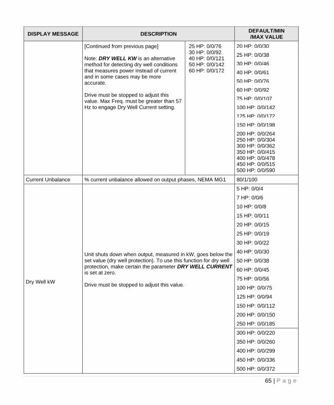
65 | P a g e
DISPLAY MESSAGE DESCRIPTION DEFAULT/MIN /MAX VALUE
[Continued from previous page] Note: DRY WELL KW is an alternative method for detecting dry well conditions that measures power instead of current and in some cases may be more accurate. Drive must be stopped to adjust this value. Max Freq. must be greater than 57 Hz to engage Dry Well Current setting.
25 HP: 0/0/76 30 HP: 0/0/92 40 HP: 0/0/121 50 HP: 0/0/142 60 HP: 0/0/172
20 HP: 0/0/30
25 HP: 0/0/38
30 HP: 0/0/46
40 HP: 0/0/61
50 HP: 0/0/76
60 HP: 0/0/92
75 HP: 0/0/107
100 HP: 0/0/142
125 HP: 0/0/172
150 HP: 0/0/198
200 HP: 0/0/264 250 HP: 0/0/304 300 HP: 0/0/362 350 HP: 0/0/415 400 HP: 0/0/478 450 HP: 0/0/515 500 HP: 0/0/590
Current Unbalance % current unbalance allowed on output phases, NEMA MG1 80/1/100
Dry Well kW
Unit shuts down when output, measured in kW, goes below the set value (dry well protection). To use this function for dry well protection, make certain the parameter DRY WELL CURRENT is set at zero. Drive must be stopped to adjust this value.
5 HP: 0/0/4
7 HP: 0/0/6
10 HP: 0/0/8
15 HP: 0/0/11
20 HP: 0/0/15
25 HP: 0/0/19
30 HP: 0/0/22
40 HP: 0/0/30
50 HP: 0/0/38
60 HP: 0/0/45
75 HP: 0/0/56
100 HP: 0/0/75
125 HP: 0/0/94
150 HP: 0/0/112
200 HP: 0/0/150
250 HP: 0/0/185
300 HP: 0/0/220
350 HP: 0/0/260
400 HP: 0/0/299
450 HP: 0/0/336
500 HP: 0/0/372
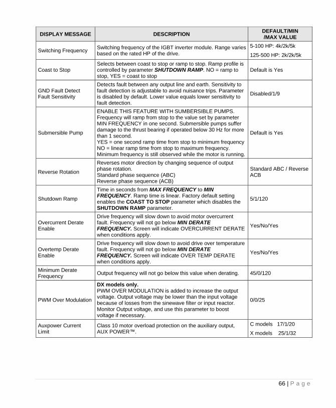
66 | P a g e
DISPLAY MESSAGE DESCRIPTION DEFAULT/MIN /MAX VALUE
Switching Frequency Switching frequency of the IGBT inverter module. Range varies based on the rated HP of the drive.
5-100 HP: 4k/2k/5k
125-500 HP: 2k/2k/5k
Coast to Stop Selects between coast to stop or ramp to stop. Ramp profile is controlled by parameter SHUTDOWN RAMP. NO = ramp to stop, YES = coast to stop
Default is Yes
GND Fault Detect Fault Sensitivity
Detects fault between any output line and earth. Sensitivity to fault detection is adjustable to avoid nuisance trips. Parameter is disabled by default. Lower value equals lower sensitivity to fault detection.
Disabled/1/9
Submersible Pump
ENABLE THIS FEATURE WITH SUMBERSIBLE PUMPS. Frequency will ramp from stop to the value set by parameter MIN FREQUENCY in one second. Submersible pumps suffer damage to the thrust bearing if operated below 30 Hz for more than 1 second. YES = one second ramp time from stop to minimum frequency NO = linear ramp time from stop to maximum frequency. Minimum frequency is still observed while the motor is running.
Default is Yes
Reverse Rotation
Reverses motor direction by changing sequence of output phase rotation. Standard phase sequence (ABC) Reverse phase sequence (ACB)
Standard ABC / Reverse ACB
Shutdown Ramp
Time in seconds from MAX FREQUENCY to MIN FREQUENCY. Ramp time is linear. Factory default setting enables the COAST TO STOP parameter which disables the SHUTDOWN RAMP parameter.
5/1/120
Overcurrent Derate Enable
Drive frequency will slow down to avoid motor overcurrent fault. Frequency will not go below MIN DERATE FREQUENCY. Screen will indicate OVERCURRENT DERATE when conditions apply.
Yes/No/Yes
Overtemp Derate Enable
Drive frequency will slow down to avoid drive over temperature fault. Frequency will not go below MIN DERATE FREQUENCY. Screen will indicate OVER TEMP DERATE when conditions apply.
Yes/No/Yes
Minimum Derate Frequency
Output frequency will not go below this value when derating. 45/0/120
PWM Over Modulation
DX models only. PWM OVER MODULATION is added to increase the output voltage. Output voltage may be lower than the input voltage because of losses from the sinewave filter or input reactor. Monitor Output voltage, and use this parameter to boost voltage if necessary.
0/0/25
Auxpower Current Limit
Class 10 motor overload protection on the auxiliary output, AUX POWER™.
C models 17/1/20
X models 25/1/32
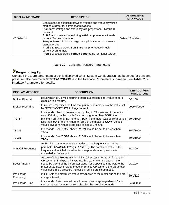
67 | P a g e
DISPLAY MESSAGE DESCRIPTION DEFAULT/MIN /MAX VALUE
V/f Selection
Controls the relationship between voltage and frequency when starting a motor for different applications. Standard: Voltage and frequency are proportional. Torque is constant. Soft Start: Limits voltage during initial ramp to reduce inrush current. Torque is reduced. Torque Boost: Boosts voltage during initial ramp to increase startup torque. Profile 1: Exaggerated Soft Start ramp to reduce inrush current even further. Profile 2: Exaggerated Torque Boost ramp for higher torque.
Default: Standard
Table 20 – Constant Pressure Parameters
Programming Tip Constant pressure parameters are only displayed when System Configuration has been set for constant pressure. The parameter SYSTEM CONFIG is in the Interface Parameters sub-menu. See Table 21 – Interface Parameters for details.
DISPLAY MESSAGE DESCRIPTION DEFAULT/MIN /MAX VALUE
Broken Pipe psi psi at which drive will determine there is a broken pipe. Value of zero disables this feature.
0/0/150
Broken Pipe Time In minutes. Specifies the time that psi must remain below the value set by BROKEN PIPE PSI to trigger a fault.
9999/0/9999
T OFF
In seconds. Used to prevent short cycling in CP systems. If the motor was off during the last cycle for a period greater than TOFF, the minimum on time of the motor is T1ON. If the motor was off for a period less than TOFF, the minimum on time of the motor is T2ON. Default values give a minimum cycle time of about 1 minute.
30/0/1000
T1 ON In seconds. See T OFF above. T1ON should be set to be less than T2ON.
15/0/1000
T2 ON In seconds. See T OFF above. T1ON should be set to be less than T2ON.
60/0/1000
Shut Off Frequency
As Hz. This parameter value is added to the frequency set by the
parameter MINIMUM FREQ (Table 19). The combined value is the
frequency at which drive will enter sleep mode when pressure is controlled at the set point.
7/0/300
Boost Amount
As a % of Max Frequency for digital CP systems, or as psi for analog CP systems. In digital CP systems, this parameter increases motor speed by the % of the parameter value, for a specified time before the motor shuts down in sleep mode. In analog CP systems the parameter value specifies a pressure increase in psi before sleep mode.
0/0/100
Pre-charge Frequency
In Hz. Sets the maximum frequency applied to the motor during the pre-charge interval.
30/1/120
Pre-charge Time In seconds. Sets the maximum time for pre-charge regardless of any sensor inputs. A setting of zero disables the pre-charge mode.
0/0/30000
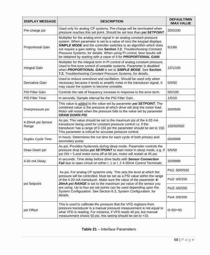
68 | P a g e
DISPLAY MESSAGE DESCRIPTION DEFAULT/MIN /MAX VALUE
Pre-charge psi Used only for analog CP systems. Pre-charge will be terminated when pressure reaches this set point. Should be set less than psi SETPOINT.
20/0/200
Proportional Gain
Multiplier for the analog error signal in an analog constant pressure system. When parameter is set to a value of zero the keypad displays SIMPLE MODE and the controller switches to an algorithm which does not require a gain setting. See Section 7.2, Troubleshooting Constant Pressure Systems, for details. When using PI control, best results will be obtained by starting with a value of 5 for PROPORTIONAL GAIN.
5/1/60
Integral Gain
Multiplier for the integral term in PI control of analog constant pressure. Used to fine tune control of unstable systems. Parameter is disabled when PROPORTIONAL GAIN is set to SIMPLE MODE. See Section 7.2, Troubleshooting Constant Pressure Systems, for details.
12/1/100
Derivative Gain Used to reduce overshoot and oscillation. Should be used only when necessary because it tends to amplify noise in the transducer signal. It may cause the system to become unstable.
0/0/50
PID Filter Gain Controls the rate of frequency increase in response to the error term. 0/0/100
PID Filter Time In seconds. Sample interval for the PID Filter Gain. 1/0/10
Overpressure psi
This value is added to the value set by parameter psi SETPOINT. The combined value is the pressure at which drive will stop the motor load. Motor will restart when the pressure falls to the value set by parameter DRAW DOWN PSI.
20/0/500
4-20mA psi Sensor Range
As psi. This value should be set to the maximum psi of the 4-20 mA transducer being used for constant pressure control i.e. if the transducer has a range of 0-150 psi the parameter should be set to 150. This parameter is critical for accurate pressure control.
150/50/500
Duplex Cycle Time In hours. Determines the run time for each cycle of both primary and secondary pump
0/0/9999
Draw Down psi As psi. Provides hysteresis during sleep mode. Parameter controls the pressure drop below psi SETPOINT to start motor in sleep mode, e.g. if psi ON = 5 and motor turns off at 50 psi, motor will restart at 45 psi.
5/0/50
4-20 mA Delay In seconds. Time delay before drive faults with Sensor Connection Fail due to open circuit on either I_1 or I_2 4-20mA Control Terminals.
3/0/9999
psi Setpoint
As psi. For analog CP systems only. This sets the level at which the pressure will be controlled. Must be set as a PSI value within the range of the 4-20 mA transducer. Make sure the value of the parameter 4-20mA psi RANGE is set to the maximum psi value of the sensor you are using. Up to four psi set points can be used depending upon the System Configuration. See Section 6.3, System Configuration, for details.
Psi1: 50/0/500
Psi2: 0/0/200
Psi3: 0/0/200
Psi4: 0/0/200
psi Offset
This is used to calibrate the pressure that the VFD registers from pressure transducer is a manual pressure measurement is not equal to what VFD is reading. For instance, if VFD reads 40 psi, but manual measurement shows 50 psi, this setting should be set to +10.
0/-50/+50
Table 21 – Interface Parameters
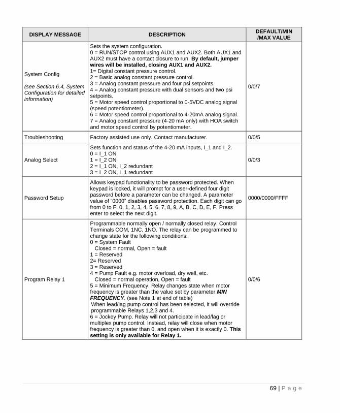
69 | P a g e
DISPLAY MESSAGE DESCRIPTION DEFAULT/MIN /MAX VALUE
System Config (see Section 6.4, System Configuration for detailed information)
Sets the system configuration. 0 = RUN/STOP control using AUX1 and AUX2. Both AUX1 and AUX2 must have a contact closure to run. By default, jumper wires will be installed, closing AUX1 and AUX2. 1= Digital constant pressure control. 2 = Basic analog constant pressure control. 3 = Analog constant pressure and four psi setpoints. 4 = Analog constant pressure with dual sensors and two psi setpoints. 5 = Motor speed control proportional to 0-5VDC analog signal (speed potentiometer). 6 = Motor speed control proportional to 4-20mA analog signal. 7 = Analog constant pressure (4-20 mA only) with HOA switch and motor speed control by potentiometer.
0/0/7
Troubleshooting Factory assisted use only. Contact manufacturer. 0/0/5
Analog Select
Sets function and status of the 4-20 mA inputs, I_1 and I_2. 0 = I_1 ON 1 = I_2 ON 2 = I_1 ON, I_2 redundant 3 = I_2 ON, I_1 redundant
0/0/3
Password Setup
Allows keypad functionality to be password protected. When keypad is locked, it will prompt for a user-defined four digit password before a parameter can be changed. A parameter value of “0000” disables password protection. Each digit can go from 0 to F: 0, 1, 2, 3, 4, 5, 6, 7, 8, 9, A, B, C, D, E, F. Press enter to select the next digit.
0000/0000/FFFF
Program Relay 1
Programmable normally open / normally closed relay. Control Terminals COM, 1NC, 1NO. The relay can be programmed to change state for the following conditions: 0 = System Fault Closed = normal, Open = fault 1 = Reserved 2= Reserved 3 = Reserved 4 = Pump Fault e.g. motor overload, dry well, etc. Closed = normal operation, Open = fault 5 = Minimum Frequency. Relay changes state when motor frequency is greater than the value set by parameter MIN FREQUENCY. (see Note 1 at end of table) When lead/lag pump control has been selected, it will override programmable Relays 1,2,3 and 4. 6 = Jockey Pump. Relay will not participate in lead/lag or multiplex pump control. Instead, relay will close when motor frequency is greater than 0, and open when it is exactly 0. This setting is only available for Relay 1.
0/0/6
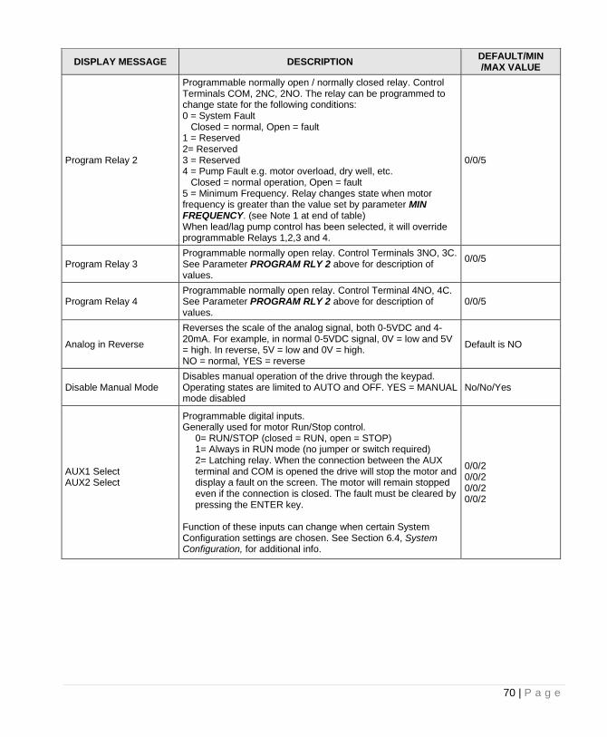
70 | P a g e
DISPLAY MESSAGE DESCRIPTION DEFAULT/MIN /MAX VALUE
Program Relay 2
Programmable normally open / normally closed relay. Control Terminals COM, 2NC, 2NO. The relay can be programmed to change state for the following conditions: 0 = System Fault Closed = normal, Open = fault 1 = Reserved 2= Reserved 3 = Reserved 4 = Pump Fault e.g. motor overload, dry well, etc. Closed = normal operation, Open = fault 5 = Minimum Frequency. Relay changes state when motor frequency is greater than the value set by parameter MIN FREQUENCY. (see Note 1 at end of table) When lead/lag pump control has been selected, it will override programmable Relays 1,2,3 and 4.
0/0/5
Program Relay 3 Programmable normally open relay. Control Terminals 3NO, 3C. See Parameter PROGRAM RLY 2 above for description of values.
0/0/5
Program Relay 4 Programmable normally open relay. Control Terminal 4NO, 4C. See Parameter PROGRAM RLY 2 above for description of values.
0/0/5
Analog in Reverse
Reverses the scale of the analog signal, both 0-5VDC and 4-20mA. For example, in normal 0-5VDC signal, 0V = low and 5V = high. In reverse, 5V = low and 0V = high. NO = normal, YES = reverse
Default is NO
Disable Manual Mode Disables manual operation of the drive through the keypad. Operating states are limited to AUTO and OFF. YES = MANUAL mode disabled
No/No/Yes
AUX1 Select AUX2 Select
Programmable digital inputs. Generally used for motor Run/Stop control.
0= RUN/STOP (closed = RUN, open = STOP) 1= Always in RUN mode (no jumper or switch required) 2= Latching relay. When the connection between the AUX terminal and COM is opened the drive will stop the motor and display a fault on the screen. The motor will remain stopped even if the connection is closed. The fault must be cleared by pressing the ENTER key.
Function of these inputs can change when certain System Configuration settings are chosen. See Section 6.4, System Configuration, for additional info.
0/0/2 0/0/2 0/0/2 0/0/2
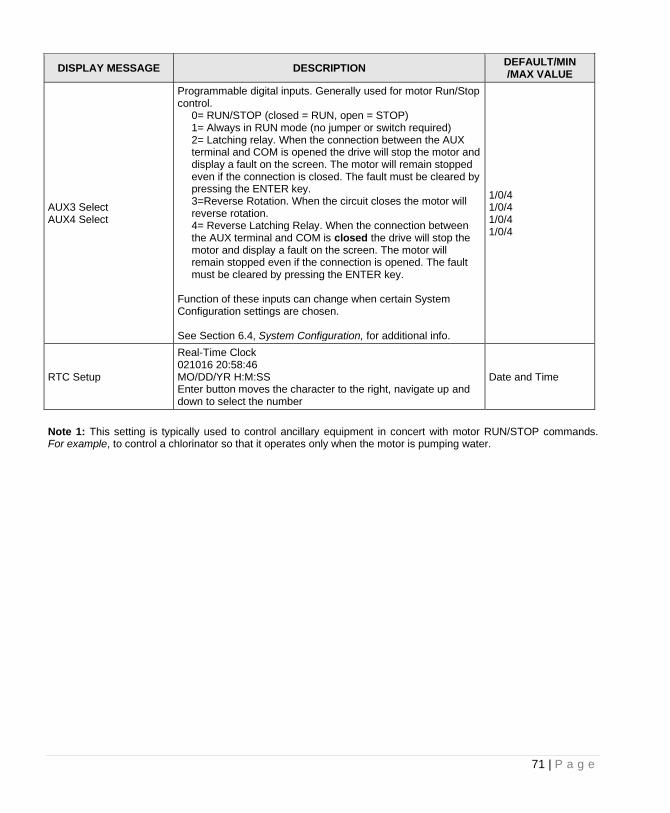
71 | P a g e
DISPLAY MESSAGE DESCRIPTION DEFAULT/MIN /MAX VALUE
AUX3 Select AUX4 Select
Programmable digital inputs. Generally used for motor Run/Stop control.
0= RUN/STOP (closed = RUN, open = STOP) 1= Always in RUN mode (no jumper or switch required) 2= Latching relay. When the connection between the AUX terminal and COM is opened the drive will stop the motor and display a fault on the screen. The motor will remain stopped even if the connection is closed. The fault must be cleared by pressing the ENTER key. 3=Reverse Rotation. When the circuit closes the motor will reverse rotation. 4= Reverse Latching Relay. When the connection between the AUX terminal and COM is closed the drive will stop the motor and display a fault on the screen. The motor will remain stopped even if the connection is opened. The fault must be cleared by pressing the ENTER key.
Function of these inputs can change when certain System Configuration settings are chosen. See Section 6.4, System Configuration, for additional info.
1/0/4 1/0/4 1/0/4 1/0/4
RTC Setup
Real-Time Clock 021016 20:58:46 MO/DD/YR H:M:SS Enter button moves the character to the right, navigate up and down to select the number
Date and Time
Note 1: This setting is typically used to control ancillary equipment in concert with motor RUN/STOP commands. For example, to control a chlorinator so that it operates only when the motor is pumping water.
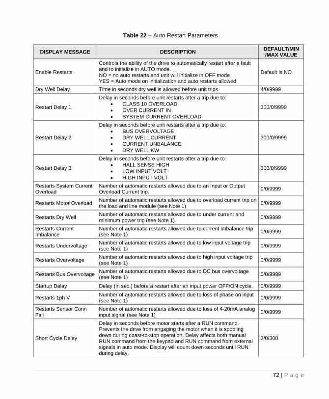
72 | P a g e
Table 22 – Auto Restart Parameters
DISPLAY MESSAGE DESCRIPTION DEFAULT/MIN /MAX VALUE
Enable Restarts
Controls the ability of the drive to automatically restart after a fault and to initialize in AUTO mode. NO = no auto restarts and unit will initialize in OFF mode YES = Auto mode on initialization and auto restarts allowed
Default is NO
Dry Well Delay Time in seconds dry well is allowed before unit trips 4/0/9999
Restart Delay 1
Delay in seconds before unit restarts after a trip due to:
• CLASS 10 OVERLOAD
• OVER CURRENT IN
• SYSTEM CURRENT OVERLOAD
300/0/9999
Restart Delay 2
Delay in seconds before unit restarts after a trip due to:
• BUS OVERVOLTAGE
• DRY WELL CURRENT
• CURRENT UNBALANCE
• DRY WELL KW
300/0/9999
Restart Delay 3
Delay in seconds before unit restarts after a trip due to:
• HALL SENSE HIGH
• LOW INPUT VOLT
• HIGH INPUT VOLT
300/0/9999
Restarts System Current Overload
Number of automatic restarts allowed due to an Input or Output Overload Current trip.
0/0/9999
Restarts Motor Overload Number of automatic restarts allowed due to overload current trip on the load and line module (see Note 1)
0/0/9999
Restarts Dry Well Number of automatic restarts allowed due to under current and minimum power trip (see Note 1)
0/0/9999
Restarts Current Imbalance
Number of automatic restarts allowed due to current imbalance trip (see Note 1)
0/0/9999
Restarts Undervoltage Number of automatic restarts allowed due to low input voltage trip (see Note 1)
0/0/9999
Restarts Overvoltage Number of automatic restarts allowed due to high input voltage trip (see Note 1)
0/0/9999
Restarts Bus Overvoltage Number of automatic restarts allowed due to DC bus overvoltage (see Note 1)
0/0/9999
Startup Delay Delay (in sec.) before a restart after an input power OFF/ON cycle. 0/0/9999
Restarts 1ph V Number of automatic restarts allowed due to loss of phase on input (see Note 1)
0/0/9999
Restarts Sensor Conn Fail
Number of automatic restarts allowed due to loss of 4-20mA analog input signal (see Note 1)
0/0/9999
Short Cycle Delay
Delay in seconds before motor starts after a RUN command. Prevents the drive from engaging the motor when it is spooling down during coast-to-stop operation. Delay affects both manual RUN command from the keypad and RUN command from external signals in auto mode. Display will count down seconds until RUN during delay.
3/0/300
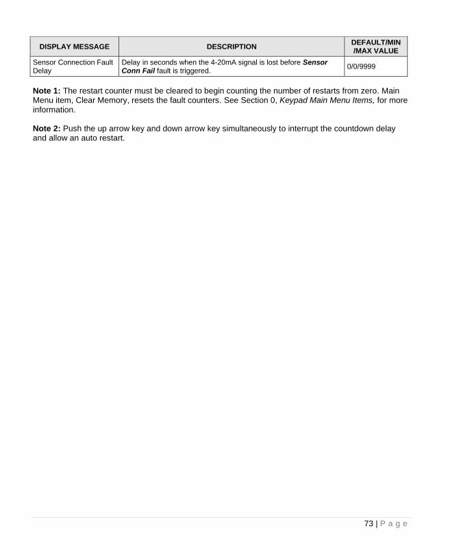
73 | P a g e
DISPLAY MESSAGE DESCRIPTION DEFAULT/MIN /MAX VALUE
Sensor Connection Fault Delay
Delay in seconds when the 4-20mA signal is lost before Sensor Conn Fail fault is triggered.
0/0/9999
Note 1: The restart counter must be cleared to begin counting the number of restarts from zero. Main Menu item, Clear Memory, resets the fault counters. See Section 0, Keypad Main Menu Items, for more information. Note 2: Push the up arrow key and down arrow key simultaneously to interrupt the countdown delay and allow an auto restart.
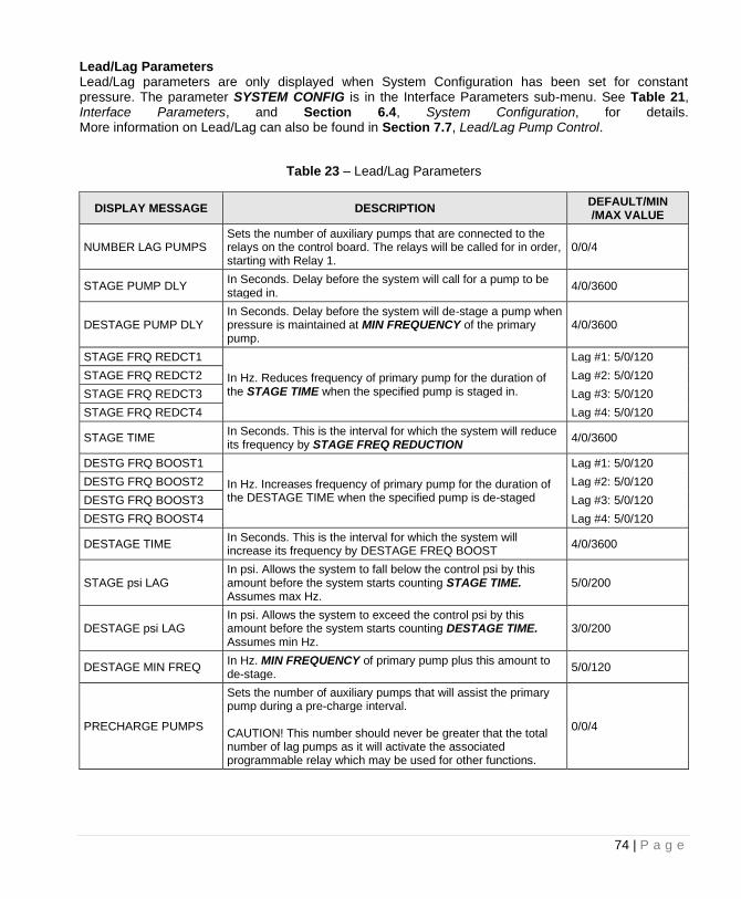
74 | P a g e
Lead/Lag Parameters Lead/Lag parameters are only displayed when System Configuration has been set for constant pressure. The parameter SYSTEM CONFIG is in the Interface Parameters sub-menu. See Table 21, Interface Parameters, and Section 6.4, System Configuration, for details. More information on Lead/Lag can also be found in Section 7.7, Lead/Lag Pump Control.
Table 23 – Lead/Lag Parameters
DISPLAY MESSAGE DESCRIPTION DEFAULT/MIN /MAX VALUE
NUMBER LAG PUMPS Sets the number of auxiliary pumps that are connected to the relays on the control board. The relays will be called for in order, starting with Relay 1.
0/0/4
STAGE PUMP DLY In Seconds. Delay before the system will call for a pump to be staged in.
4/0/3600
DESTAGE PUMP DLY In Seconds. Delay before the system will de-stage a pump when pressure is maintained at MIN FREQUENCY of the primary pump.
4/0/3600
STAGE FRQ REDCT1
In Hz. Reduces frequency of primary pump for the duration of the STAGE TIME when the specified pump is staged in.
Lag #1: 5/0/120
STAGE FRQ REDCT2 Lag #2: 5/0/120
STAGE FRQ REDCT3 Lag #3: 5/0/120
STAGE FRQ REDCT4 Lag #4: 5/0/120
STAGE TIME In Seconds. This is the interval for which the system will reduce its frequency by STAGE FREQ REDUCTION
4/0/3600
DESTG FRQ BOOST1
In Hz. Increases frequency of primary pump for the duration of the DESTAGE TIME when the specified pump is de-staged
Lag #1: 5/0/120
DESTG FRQ BOOST2 Lag #2: 5/0/120
DESTG FRQ BOOST3 Lag #3: 5/0/120
DESTG FRQ BOOST4 Lag #4: 5/0/120
DESTAGE TIME In Seconds. This is the interval for which the system will increase its frequency by DESTAGE FREQ BOOST
4/0/3600
STAGE psi LAG In psi. Allows the system to fall below the control psi by this amount before the system starts counting STAGE TIME. Assumes max Hz.
5/0/200
DESTAGE psi LAG In psi. Allows the system to exceed the control psi by this amount before the system starts counting DESTAGE TIME. Assumes min Hz.
3/0/200
DESTAGE MIN FREQ In Hz. MIN FREQUENCY of primary pump plus this amount to de-stage.
5/0/120
PRECHARGE PUMPS
Sets the number of auxiliary pumps that will assist the primary pump during a pre-charge interval. CAUTION! This number should never be greater that the total number of lag pumps as it will activate the associated programmable relay which may be used for other functions.
0/0/4
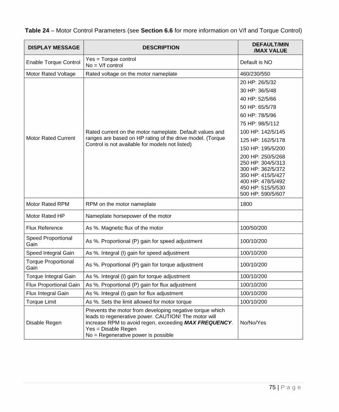
75 | P a g e
Table 24 – Motor Control Parameters (see Section 6.6 for more information on V/f and Torque Control)
DISPLAY MESSAGE DESCRIPTION DEFAULT/MIN /MAX VALUE
Enable Torque Control Yes = Torque control No = V/f control
Default is NO
Motor Rated Voltage Rated voltage on the motor nameplate 460/230/550
Motor Rated Current Rated current on the motor nameplate. Default values and ranges are based on HP rating of the drive model. (Torque Control is not available for models not listed)
20 HP: 26/5/32
30 HP: 36/5/48
40 HP: 52/5/66
50 HP: 65/5/78
60 HP: 78/5/96
75 HP: 98/5/112
100 HP: 142/5/145
125 HP: 162/5/178
150 HP: 195/5/200
200 HP: 250/5/268 250 HP: 304/5/313 300 HP: 362/5/372 350 HP: 415/5/427 400 HP: 478/5/492 450 HP: 515/5/530 500 HP: 590/5/607
Motor Rated RPM RPM on the motor nameplate 1800
Motor Rated HP Nameplate horsepower of the motor
Flux Reference As %. Magnetic flux of the motor 100/50/200
Speed Proportional Gain
As %. Proportional (P) gain for speed adjustment 100/10/200
Speed Integral Gain As %. Integral (I) gain for speed adjustment 100/10/200
Torque Proportional Gain
As %. Proportional (P) gain for torque adjustment 100/10/200
Torque Integral Gain As %. Integral (I) gain for torque adjustment 100/10/200
Flux Proportional Gain As %. Proportional (P) gain for flux adjustment 100/10/200
Flux Integral Gain As %. Integral (I) gain for flux adjustment 100/10/200
Torque Limit As %. Sets the limit allowed for motor torque 100/10/200
Disable Regen
Prevents the motor from developing negative torque which leads to regenerative power. CAUTION! The motor will increase RPM to avoid regen, exceeding MAX FREQUENCY. Yes = Disable Regen No = Regenerative power is possible
No/No/Yes

76 | P a g e
5.4 All Parameters List In order to aid in troubleshooting, a numbered parameter list containing all parameters is available for use. Some parameters are visible that are not always used. In this case, the word “Disabled” is shown, and programming functionality is disabled for that parameter. Each parameter is numbered and ordered in the following order:
INDEX PARAMETER CATEGORY
1-19 Operating
20-36 Auto Restart
37-51 Interface
52-76 Constant Pressure
77-93 Lead Lag
5.5 Changed Parameter List This is a list of all parameters that have been changed from their default values. This allows for quick and easy programming of previously changed parameter values. Parameters that have been edited will show up in the same order as described in the table above: Operating -> Auto Restart -> Interface -> Constant Pressure -> Lead Lag. The total number of changed parameters, and the current index of changed parameters, will be displayed at the top of the screen. If there are no changed parameters, then “No Changed Parameters” will be shown.
77 | P a g e
OPERATION 6.1 Commissioning the Unit It is always advisable to check the operating status of the drive and its load before commencing regular operation. Initial Operation Verify the following:
1. The unit is securely attached to the proper mounting surface 2. The unit’s input terminals are connected to an appropriate power source 3. An appropriately rated motor is connected to the output terminals 4. The motor is secured and properly mounted
Perfect Pressure™ Setup Upon the first initialization of the unit (or after restoring factory defaults of all parameters) the drive will prompt the user to select or decline a quick setup for constant pressure. The display will read SETUP CONST PRESS YES (ENT) / NO (BACK). Press the ENTER key to set up Perfect Pressure or the BACK key to decline. Basic parameters for analog constant pressure can be set without navigating through the complete menu options. Refer to Section 7.3, PerfectPressure™ Setup – Analog Constant Pressure, for the information required to complete the setup, and have this information ready to enter when commissioning the unit. 6.2 Ground Fault Detection These drives are equipped with a feature to detect a fault between any of the output lines and earth. See Table 19, Operating Parameters, GND FAULT DETECT, for more information on using this parameter. If a ground fault is strong enough to trigger the parameter GND FAULT DETECT, the drive will not allow the IGBTs to switch. However, this does not protect the drive from damage in all situations. If a ground fault occurs, immediately disconnect the input power! Long motor leads and a dV/dT filter can cause nuisance indications of a ground fault. If a megger does not indicate a ground fault, the sensitivity of the ground fault detection may need to be reduced by reducing the value of parameter GND FAULT DETECT.
CAUTION: Before the motor is connected to the output terminals, check all output lines for line-to-ground faults using a megger. There is a direct path through the drive circuitry for ground fault currents that can be triggered when power is applied to the input terminals, even though the output switches are not activated. These currents can cause serious damage to drive circuitry and are not covered under warranty.
WARNING! The default operating mode when the unit is energized is OFF. If the parameter ENABLE RESTARTS has been set to allow restarts, the unit will energize in AUTO mode. If the external controls are calling for a motor run condition, the motor will start. Make sure either external controls are off before energizing the input, or as soon as the unit has initialized, push the STOP/OFF key until OFF appears on the display. Refer to Section 4.1, Using the Keypad and Display, for instructions on operating the keypad.
78 | P a g e
VFD Set-up Procedure
1. If remote or automatic ON/OFF function is required, connect remote switch leads to the AUX1 and COM terminals. An additional remote switch or jumper wire may be connected to the AUX2 and COM terminals. The AUX1 to COM and AUX2 to COM jumper wires will already be installed by the factory, remove as needed for pressure switches or remote ON/OFF switches.
2. If a Constant Pressure (CP) water system will be operated, connect the pressure sensors to the appropriate Control Terminals. See Section 6.4, System Configuration, and Section 7, Constant Pressure Systems for details.
3. Apply power to the input terminals of the drive by turning on the input circuit breaker or disconnect switch.
4. The graphic display will scroll through several start-up sequence messages.
5. If the ENABLE RESTARTS parameter is set to allow restarts, the drive will initialize in AUTO mode and the motor will run when control signals call for a motor run condition. In order to prevent the motor from running at start-up, immediately after initialization, press the STOP/OFF key until OFF appears on the display or open AUX1 or AUX2.
6. Confirm that the unit has properly energized, and the display indicates the OFF mode.
7. Using the keypad and display, navigate to the Main Menu item, CHANGE PARAMETER VAULES, to set the following parameters for basic operation (see Table 19 - Table 22 for details):
• INTERFACE PARAMETERS > SYSTEM CONFIG This parameter is critical to the operation of the system. The default setting is for simple ON/OFF operation. See Section 6.4, System Configuration, for complete information.
• OPERATING PARAMETERS > OVERCURRENT LIMIT This parameter sets the motor overload protection. See Section 6.3, Motor Overload Protection, for complete information.
• AUTO RESTART PARAMETERS > ENABLE RESTARTS This parameter enables the drive to initialize in AUTO mode and to restart automatically after a fault. Factory default does not allow auto restarts.
8. Push the MANUAL key until MANUAL appears on the display for manual mode, then push RUN to start the motor. In manual mode, the RUN key will override an open AUX terminal or other external control signal. Push the STOP key to stop the motor in manual mode.
CAUTION: In manual mode, pushing the RUN key will override all external control signals, including constant pressure sensors. Dangerous pressure rise in closed plumbing systems is possible.
9. The motor will start with the default acceleration ramp time of 0-30 Hz in one second, then 30-60 Hz in eight seconds.
10. Confirm that the motor rotation is correct. Swapping any two of the output leads will reverse the motor rotation.
11. After initial power-up, use the keypad and display to navigate to CHANGE PARAMETER VALUES to set any other adjustable parameters you wish to be different from the factory defaults.
79 | P a g e
6.3 Motor Overload Protection These drives are equipped with adjustable solid state motor overload protection. Protection is based on a Class 10 trip curve. Motor overload settings are selected by navigating to the appropriate menu item using the keypad and display. Thermal Memory and Thermal Memory Retention The motor overload protection is equipped with thermal memory and thermal memory retention capabilities. THERMAL MEMORY is the ability of an overload protective system to approximate the heating cooling of a protected motor during operation. THERMAL MEMORY RETENTION maintains the thermal memory upon shutdown or power loss. This includes retention of the last thermal value, and may include an ongoing reduction of this thermal value to reflect the cooling of the motor. This information will be used by the overload protective system to approximate the thermal state of the motor upon restart.
CAUTION: Do not attempt to restart the motor immediately after a motor overload fault. The motor overload protection system uses a timer to approximate motor cooling and may trigger an immediate overload fault if the motor is restarted too soon. If the drive loses power immediately after a motor overload fault, it will not begin counting down the time that approximates motor cooling until the drive is energized. If the drive faults with a motor overload, it may be necessary to allow time for this countdown before the motor is operated even though the motor has been off for an extended period of time. Setting Motor Overload Protection with Keypad To set motor overload protection with the keypad, navigate to the Main Menu item CHANGE PARAMETER VALUES > CHANGE OPERATING PARAMETERS > OVERCURRENT LIMT. Refer to Section 4.3, Changing Parameter Values, Table 19 Operating Parameters for detailed instructions. 6.4 System Configuration The drive is capable of operating several types of systems, including constant pressure water systems, and simple ON/OFF control from remote switches. The correct system configuration must be selected for proper operation of the different types of control systems! System configuration is set by navigating to the keypad Main Menu item CHANGE PARAMETER VALUES > CHANGE INTERFACE PARAMETERS > SYSTEM CONFIG. Refer to Section 5.1, Changing Parameter Values, Table 21, Interface Parameters, for detailed instructions. Below is a brief description of each configuration setting:
• System Configuration = 0: Basic RUN/STOP operation. This is the factory default configuration for basic operation of the drive that allows RUN/STOP control of the motor in AUTO mode using a dry contact on AUX1 and/or AUX2. Both AUX1 and AUX2 must have a contact closure to run. AUX3 and AUX4 can be enabled if needed.
80 | P a g e
• System Configuration = 1: Digital Constant Pressure. Use this setting to operate digital constant pressure systems. Only use digital pressure switches purchased from or approved by Phase Technologies. Refer to Section Error! Reference source not found., Digital Constant Pressure Systems, for more information on operating the drive in this mode.
• System Configuration = 2: Basic Analog Constant Pressure. Use this setting to operate analog constant pressure systems with a 4-20 mA transducer. Refer to Section 0, Analog Constant Pressure Systems, for more information on operating the drive in this mode. Refer to Figure 21 for a diagram illustrating connection of the transducer to Control Terminals.
• System Configuration = 3: Analog Constant Pressure with redundant sensors and up to four PSI Setpoints. This configuration allows the use of two 4-20 mA transducers. The primary sensor is connected to the I_1in+ and I_1in- Control Terminals, with the backup sensor connected to the I_2in+ and I_2in- Control Terminals. If the primary sensor fails, the backup sensor will automatically take over control of constant pressure at the same settings. Multiple pressure psi setpoints can also be used in this configuration. Enter the psi value of these setpoints in the Constant Pressure parameter, psi SETPOINT, which are denoted as psi1, psi2, psi3 and psi4. These four setpoints will be visible in the menu structure only when System Configuration 3 has been selected.
The table below shows what set point the system will follow based on the 0,1 configuration of the AUX3 and AUX4 terminals. 0 = closed, 1 = open. Aux1 and AUX2 must also be closed for the system to run.
Table 25 – System Configuration Setpoints
AUX3 AUX4
0 0 psi1 SETPOINT
1 0 psi2 SETPOINT
0 1 psi3 SETPOINT
1 1 psi4 SETPOINT
System Configuration = 4: Analog Constant Pressure with dual sensors and two psi set points. In this configuration a 4-20 mA transducer connected to Control Terminals I_1in+ and I_1in- controls pressure equal to psi1, and a second sensor connected to the I_2in+ and I_2in- Control Terminals controls pressure equal to psi2. Enter the PSI value of these set points in the Constant Pressure parameter, PSI SETPOINT, which are denoted as psi1 and psi2. These two set points will be visible in the menu structure only when System Configuration 4 has been selected. The digital input on Control Terminals AUX2 control selection of the different pressure set points when the pump is operating. AUX1 functions as a RUN/STOP input where AUX1 closed = RUN, AUX1 open = STOP. The control scheme for the two psi set points is as follows:
1. If AUX2 is open the sensor on I_1in will be in control and psi set point will be equal to psi1. 2. If AUX2 is closed the sensor on I_2in will be in control and psi set point will be equal to psi2.
• System Configuration = 5: Speed control with 0-5VDC analog signal. Use this setting for motor speed control by a potentiometer or an external 0-5 VDC source connected to the 0-5 VDC Control Terminals. Refer to Figure 22 for a diagram illustrating connection of the potentiometer or the voltage
81 | P a g e
source to Control Terminals. The drive will ignore the DC analog signal until it reaches a value proportional to the speed set by the parameter, MIN FREQUENCY, which has a factory default setting of 30 Hz. For speed control across the full scale range of the analog signal, set MIN FREQUENCY to the minimum value of 5 Hz. AUX1 and AUX2 must be closed to run in this System Configuration.
• System Configuration = 6: Speed control with 4-20 mA analog signal. Use this setting for motor speed control proportional to a 4-20 mA analog signal. The drive will ignore the analog signal until it reaches a value proportional to the speed set by the parameter, MIN FREQUENCY, which has a factory default setting of 30 Hz. For speed control across the full scale range of the analog signal, set MIN FREQUENCY to the minimum value of 5 Hz. Refer to Figure 21 for a diagram illustrating connection of the transducer to Control Terminals. When using an external 4-20 mA source, connect the leads to I_1in- and COM. AUX1 and AUX2 must be closed to run in this System Configuration.
CAUTION: This is not a constant pressure control mode. Motor speed will be controlled in a linear fashion proportional to the analog signal.
System Configuration = 7: Analog constant pressure with HOA and speed potentiometer. This setting allows the user to either turn the motor off, control motor speed with a potentiometer or operate in analog constant pressure mode using an HOA switch. Access to the keypad is not required to operate in this mode. A mechanical HOA switch changes the state of AUX1 and AUX3 Control Terminals to change to mode of operation in this configuration. A potentiometer is connected to the 0-5 VDC control Terminals, a 4-20 mA analog transducer is connected to the I+ and I- Control Terminals, and a double pole, triple throw HOA switch is connected to AUX1 and AUX3 Control Terminals.
• AUX1 controls for motor run and stop. When the switch is in the OFF position AUX1 is open and the motor will stop. When it is closed (either HAND or AUTO position) the motor will run. AUX3 toggles between analog constant pressure and motor speed control by the potentiometer. When the switch is in the AUTO position and AUX3 is open the drive will operate in analog constant pressure mode. When the switch is in the HAND position it is closed and the potentiometer will control motor speed.
• Refer to Figure 23 for a diagram illustrating connection of the transducer to Control Terminals. AUX2 must be closed to run in the Analog CP Mode (Auto), and AUX 2 is ignored when the speed potentiometer is used (Hand).
The System Configuration must be in any of the constant pressure modes to enable Pre-Charge of the plumbing system or Lead/Lag pump control. See Section 7.6, Pre-Charge and Section 7.7, Lead/Lag Pump Control for more information. 6.5 Start-Up and Shut-Down Ramp Times Start-up and shut-down ramp times specify the time required to go from Minimum Frequency to Maximum Frequency or vice versa. Ramp times and profiles are adjustable by changing Operating Parameters through the keypad and text display. The factory default setting for START UP RAMP is 8 seconds and SHUTDOWN RAMP has been disabled through the COAST TO STOP parameter to reduce nuisance tripping from high inertia loads.
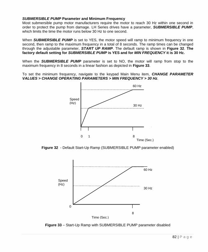
82 | P a g e
SUBMERSIBLE PUMP Parameter and Minimum Frequency Most submersible pump motor manufacturers require the motor to reach 30 Hz within one second in order to protect the pump from damage. LH Series drives have a parameter, SUBMERSIBLE PUMP, which limits the time the motor runs below 30 Hz to one second. When SUBMERSIBLE PUMP is set to YES, the motor speed will ramp to minimum frequency in one second, then ramp to the maximum frequency in a total of 8 seconds. The ramp times can be changed through the adjustable parameter, START UP RAMP. The default ramp is shown in Figure 32. The factory default setting for SUBMERSIBLE PUMP is YES and for MIN FREQUENCY it is 30 Hz. When the SUBMERSIBLE PUMP parameter is set to NO, the motor will ramp from stop to the maximum frequency in 8 seconds in a linear fashion as depicted in Figure 33. To set the minimum frequency, navigate to the keypad Main Menu item, CHANGE PARAMETER VALUES > CHANGE OPERATING PARAMETERS > MIN FREQUENCY > 30 Hz.
Figure 32 - Default Start-Up Ramp (SUBMERSIBLE PUMP parameter enabled)
Figure 33 – Start-Up Ramp with SUBMERSIBLE PUMP parameter disabled
Speed (Hz)
0 1
30 Hz
60 Hz
Time (Sec.)
8
Speed (Hz)
0
30 Hz
60 Hz
Time (Sec.)
8
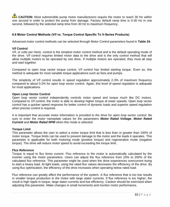
83 | P a g e
CAUTION: Most submersible pump motor manufacturers require the motor to reach 30 Hz within one second in order to protect the pump from damage. Factory default ramp time is 0-30 Hz in one second, followed by the selected ramp time from 30 Hz to maximum frequency. 6.6 Motor Control Methods (V/f vs. Torque Control Specific To V-Series Products) Advanced motor control methods can be selected through Motor Control parameters found in Table 24. V/f Control V/f, or volts per Hertz, control is the simplest motor control method and is the default operating mode of the drive. V/f control requires limited motor data to the drive and is the only control method that will allow multiple motors to be operated by one drive. If multiple motors are operated, they must all stop and start together. Compared to open loop vector torque control, V/f control has limited starting torque. Even so, this method is adequate for most variable torque applications such as fans and pumps. The simplicity of V/f control results in speed regulation approximately 2-3% of maximum frequency compared to about 0.2% for open loop vector control. Again, this level of speed regulation is adequate for most applications. Open Loop Vector Control Open loop vector control independently controls motor speed and torque much like DC motors. Compared to V/f control, the motor is able to develop higher torque at lower speeds. Open loop vector control has a quicker speed response for better control of dynamic loads and superior speed regulation when precise control is required. It is important that accurate motor information is provided to the drive for open loop vector control. Be sure to enter the motor nameplate values for the parameters Motor Rated Voltage, Motor Rated Current and Motor Rated RPM when this mode is selected. Torque Limit This parameter allows the user to select a motor torque limit that is less than or greater than 100% of motor torque. Torque limits can be used to prevent damage to the motor and the loads it operates. This parameter is applicable for both motoring mode (positive torque) and regenerative mode (negative torque). The drive will reduce motor speed to avoid exceeding the torque limit. Flux Reference Torque is equal to flux times current. Flux reference to the motor is automatically calculated by the inverter using the motor parameters. Users can adjust the flux reference from 10% to 200% of the calculated flux reference. This parameter might be used when the drive experiences overcurrent trying to start a heavy load. At light loads, using the rated flux values decreases the efficiency of the drive. By using flux optimization, the efficiency of the drive increases when operating below rated load. Flux reference can greatly affect the performance of the system. A flux reference that is too low results in smaller torque production in the motor with large stator currents. If flux reference is too higher, the result is high ripple in torque, large stator currents and low efficiency. Caution should be exercised when adjusting this parameter. Make changes in small increments and monitor motor performance.
84 | P a g e
CONSTANT PRESSURE SYSTEMS LH and DX drives can be configured as constant pressure (CP) water systems using either an analog pressure transducer (analog constant pressure system) or pressure switches (digital constant pressure system). A CP water system includes a pressure tank, a pressure gauge to observe system pressure, and pressure switches or sensors 7.1 Control Principles of Constant Pressure Systems In a CP system, a target pressure for the system is set on the switch itself (digital CP) or through the keypad (analog CP). Signals from the sensors interact with firmware to control the motor speed and maintain constant water pressure. In a strict definition of a constant pressure system, the pump would never turn off. If the pressure differential between pump-on and pump-off was actually zero, the noise fluctuations of the transducer output would cause the motor to cycle constantly between the on and off states. For this reason, most applications will want to accept a small differential pressure in the system in order to prevent either continuous running of the motor or constant on/off cycling of the motor. Three basic conditions must be met in order for the pump to shut down and enter sleep mode:
1. The pressure in the system must be at the pressure control point set by the parameter psi SETPOINT (analog CP) or at the pressure determined by the setting on the digital pressure switch.
2. The frequency is below SHUTOFF FREQUENCY (as defined as MIN FREQUENCY + input value) or measured pressure is above OVERPRESSURE psi (as defined as psi SETPOINT + the input value.
3. The time expired since the pump started after the last OFF cycle must be greater than parameter T1ON or T2ON.
Preventing Short Cycling During Low Flow Conditions When a CP system is in a low flow state, it may be desirable to turn the motor off (sleep mode) in order to conserve energy and preserve the motor. The adjustable parameters TOFF, T1ON, T2ON, SHUTOFF FREQUENCY, OVERPRESSURE psi, DRAWDOWN PSI, and BOOST AMOUNT control when the motor is turned off, how long it is off, and prevent short cycling of the motor at low flow rates. More information including default values for these parameters can be found in Table 20. DRAWDOWN PSI and BOOST AMOUNT The primary method to prevent short cycling is to allow a differential between the pressure at which the pump turns off and the pressure at which it restarts. Two parameters, DRAWDOWN PSI and BOOST AMOUNT, control this differential. BOOST AMOUNT specifies the increase in pressure above psi SETPOINT just before the pump shuts down to enter sleep mode, while DRAWDOWN PSI specifies the pressure drop below psi SETPOINT at which the pump restarts. For example, assume psi SETPOINT = 50, BOOST AMOUNT = 5, and DRAWDOWN PSI = 5. When the pump is ready to enter sleep mode, the pump will boost to 55 psi, then restart when the pressure falls to 45 psi. These two parameters can be used together or independently to create a dead band in pressure control. OVERPRESSURE PSI and SHUTOFF FREQ can also be set to tell the drive when to enter sleep mode. OVERPRESSURE psi (analog CP only) is the system pressure at which the drive will go to
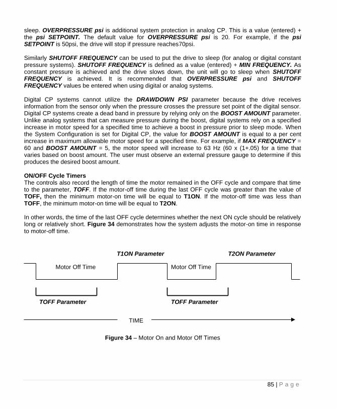
85 | P a g e
sleep. OVERPRESSURE psi is additional system protection in analog CP. This is a value (entered) + the psi SETPOINT. The default value for OVERPRESSURE psi is 20. For example, if the psi SETPOINT is 50psi, the drive will stop if pressure reaches70psi. Similarly SHUTOFF FREQUENCY can be used to put the drive to sleep (for analog or digital constant pressure systems). SHUTOFF FREQUENCY is defined as a value (entered) + MIN FREQUENCY. As constant pressure is achieved and the drive slows down, the unit will go to sleep when SHUTOFF FREQUENCY is achieved. It is recommended that OVERPRESSURE psi and SHUTOFF FREQUENCY values be entered when using digital or analog systems. Digital CP systems cannot utilize the DRAWDOWN PSI parameter because the drive receives information from the sensor only when the pressure crosses the pressure set point of the digital sensor. Digital CP systems create a dead band in pressure by relying only on the BOOST AMOUNT parameter. Unlike analog systems that can measure pressure during the boost, digital systems rely on a specified increase in motor speed for a specified time to achieve a boost in pressure prior to sleep mode. When the System Configuration is set for Digital CP, the value for BOOST AMOUNT is equal to a per cent increase in maximum allowable motor speed for a specified time. For example, if MAX FREQUENCY = 60 and BOOST AMOUNT = 5, the motor speed will increase to 63 Hz (60 x (1+.05) for a time that varies based on boost amount. The user must observe an external pressure gauge to determine if this produces the desired boost amount. ON/OFF Cycle Timers The controls also record the length of time the motor remained in the OFF cycle and compare that time to the parameter, TOFF. If the motor-off time during the last OFF cycle was greater than the value of TOFF, then the minimum motor-on time will be equal to T1ON. If the motor-off time was less than TOFF, the minimum motor-on time will be equal to T2ON. In other words, the time of the last OFF cycle determines whether the next ON cycle should be relatively long or relatively short. Figure 34 demonstrates how the system adjusts the motor-on time in response to motor-off time.
Figure 34 – Motor On and Motor Off Times
TOFF Parameter
TIME
T1ON Parameter
Motor Off Time
TOFF Parameter
Motor Off Time
T2ON Parameter
86 | P a g e
Fine Tuning With PI Control PI control is not available when operating in Digital CP mode. When operating in analog CP mode, if the parameter PROPORTIONAL GAIN is set to a value less than 1, the keypad displays SIMPLE MODE and the controller uses an algorithm that is not PI control. Simple Mode requires less fine tuning than PI control, but in some applications may not provide the control and stability desired. The stability of the constant pressure system (i.e., its tendency not to exhibit pressure oscillations) is determined by parameters set on the keypad, the flow rate of the pump, and the volume of the pressure tank. Stability of a system with a large maximum flow rate and a small pressure tank will be more difficult to control and may require de-tuning the system to accept larger variations in the system pressure and longer response times. Analog constant pressure systems with PI (proportional integral) control provide more options to fine tune pressure control than digital constant pressure systems or analog systems in Simple Mode. Systems that are not adequately controlled with the Simple Mode may require fine tuning by switching to PI control. Increasing the value of PROPORTIONAL GAIN to any value greater than SIMPLE MODE will initiate PI control. Pressure control is achieved by adjusting the values of PROPORTIONAL GAIN and INTEGRAL GAIN. Larger values for PROPORTIONAL GAIN and INTEGRAL GAIN give smaller error in the pressure, but also make the system more susceptible to oscillation. The following pages of this Section will provide more information on tuning PI control. Emergency Over-Pressure Limit Switch Both digital and analog CP systems have the option of connecting an emergency over-pressure limit switch to the AUX2 terminals in case the main pressure control system fails. The emergency over-pressure set-point should be at least 10 psi higher than the system control pressure to prevent nuisance tripping. 7.2 Troubleshooting Constant Pressure Systems A variety of conditions in a plumbing system can lead to less than optimum performance of constant pressure control while using the factory default settings. The default settings are designed to operate a range of plumbing systems, but there can be many variables in a plumbing system that requires adjustment of the constant pressure parameters. In order for the drive to enter sleep mode while operating in constant pressure mode, three conditions must be met:
1. The pressure in the system must be at the pressure control point set by the parameter psi SETPOINT (for analog systems) or at the pressure determined by the setting on the digital pressure switch
2. The frequency is below SHUTOFF FREQ (as defined as MIN FREQUENCY + input value) or measured pressure is above OVERPRESSURE psi (as defined as psi SETPOINT + the input value).
3. The time expired since the pump started after the last OFF cycle must be greater than parameter T1ON or T2ON
When these conditions have been met, the drive will go to sleep. The duration of which the drive is asleep depends on the rate at which the system bleeds down and the width of the dead band. When setting and testing a constant pressure system, try to operate as close as possible to the normal
87 | P a g e
operating conditions. Low flow in a high capacity system (and vice versa) usually requires some adjusting of the parameters. SIMPLE MODE Control in a Digital CP System Phase Technologies has developed a proprietary controller which involves fewer parameters to tune constant pressure performance. When the PROPORTIONAL GAIN parameter is set at the lowest value, the display will read "SIMPLE MODE". In SIMPLE MODE a set of control equations is used which may not require the user to tune the system to obtain acceptable performance. A well-tuned PI controller will result in smoother pressure control but may not be required. When the controller is in simple mode the only parameters which affect the pressure control loop are the psi SETPOINT, STARTUP RAMP, SHUTDOWN RAMP and BOOST AMOUNT, which function in the same way as they do in the PI control mode. Adjusting ramp times may smooth out any oscillation or overshoot in simple mode. If pressure is not adequately controlled, switch to PI control by increasing parameter PROPORTIONAL GAIN. Using PI Control in an Analog CP System When using an analog pressure transducer for control in constant pressure water systems, it may be desirable to use a proportional-integral (PI) controller in the feedback loop. This type of controller has a proportional gain and integral gain which can be tuned by the user to obtain optimum performance for each particular application. Increase parameter PROPORTIONAL GAIN to switch control from Simple Mode to PI control. It is recommended to start with a parameter value of 5. A proportional gain value too low will result in slow response time to reach the psi setpoint. A value too high will result in overshoot of the psi setpoint and may create wild oscillation of pressure. First, attempt to control pressure by adjusting parameter PROPORTIONAL GAIN, leaving parameter INTEGRAL GAIN at the default value of 50. If adequate control cannot be obtained by adjusting proportional gain, set proportional gain at the value that gives the best control, then adjust integral gain to improve pressure control. For difficult to control systems, a derivative term can be introduced for PID control, which can help control pressure oscillation and overshoot. Increase the value of parameter DERIVATIVE GAIN to a value greater than zero to enable PID control. This parameter should be used only when necessary as it tends to amplify noise in the transducer signal. The system may become unstable. The parameters PID FILTER GAIN and PID FILTER TIME help to prevent overshoot. It may be advisable to contact the factory for assistance when using PID control for the first time. In general, conceptual terms, proportional gain impacts how quickly the system responds to pressure changes and integral gain impacts the accuracy of pressure tracking. Adjusting ramp times can also be considered. Increasing ramp time will damp response to pressure changes, while decreasing ramp time will quicken the response.
CAUTION: Long ramp times can interfere with PI control of constant pressure. It is advisable to start with factory default ramp times. Pressure Control at Minimum Speed There is a possibility of conflict between the minimum pump speed setting, controlled by the parameter MIN FREQUENCY, and the pressure setting of the transducer. That is, if under no-flow conditions the pump at its minimum speed setting produces a pressure greater than the desired set-point, either the minimum speed will have to be reduced (not an option with submersible pumps) or the pressure set-
88 | P a g e
point will have to be increased. Most pumps should not produce enough pressure head at 30Hz for this to be an issue. Boost in a Digital Constant Pressure System In a digital CP system the drive can only determine the pressure of the system at the set-point. Based on the characteristics of the on/off signals from the switch, which occur at the set-point, it maintains pressure. The parameter BOOST AMOUNT in a digital system is a per cent increase in speed, not in pressure, because the digital switch cannot determine a pressure beyond its set-point. In an analog system the BOOST AMOUNT is a specified psi, so the user can accurately control the boost pressure through the parameter setting on the keypad. For example, if boost of 5 psi above control pressure is desired, simply set parameter BOOST AMOUNT to 5. In a digital system BOOST AMOUNT is an increase in speed for a given time as a per cent of the speed the pump was running when the switch last opened at the set-point. For example, if pressure is controlled at a speed of 30 Hz, a BOOST AMOUNT value of 10 would be 10% of 30 Hz or 3 Hz. In low flow systems where the pressure is controlled at low speed, the BOOST AMOUNT value may need to be significantly higher than it would be set in an analog system under the same conditions. 7.3 PerfectPressure™ Setup – Analog Constant Pressure Upon the first initialization of the unit (or after restoring factory defaults of all parameters using the Two Button Reset Procedure, page 63) the drive will prompt the user to select or decline a quick setup for constant pressure. The display will read SETUP CONST PRES YES(ENTER)/NO(HOME). Press the ENTER key to set up PerfectPressure or the HOME key to decline. Basic parameters for analog constant pressure can be set without navigating through the complete menu options. Follow this procedure to set up PerfectPressure:
1. SETUP CONST PRES YES (ENTER) / NO (HOME) - Press the ENTER key to proceed. 2. 4-20mA psi RANGE - This parameter sets the range of the 4-20mA pressure sensor. The
factory default is 150 since the standard sensor provided by the factory has a maximum range of 150 psi. If necessary, use the arrow keys to change the value, then press ENTER, or simply press ENTER to proceed.
3. psi SETPOINT - This value determines the pressure you want to maintain. The factory default is 50 psi. Use the arrow keys to change if desired. Press ENTER to proceed.
4. SUBMERSIBLE PUMP - This parameter sets the ramp profile for a submersible pump. YES = submersible pump, NO = vertical pump. For submersible pumps the frequency accelerates from 0-30 Hz in one second, then follows the ramp time from 30 Hz to maximum frequency. If NO is selected the frequency will increase in a linear fashion from zero to max frequency.
5. ENABLE RESTARTS – YES (ENTER) / NO (HOME) – enabling restarts controls the ability of the drive to automatically restart after a power failure. The drive will initialize in AUTO mode after power is restored if YES is selected. If NO is selected, the drive will remain OFF when power is restored.
6. OVERCURRENT LIMIT – Setting for motor overload protection (service factor amp rating for the motor).
89 | P a g e
CAUTION: Most submersible pump motor manufacturers require the motor to reach 30 Hz within one second in order to protect the pump from damage. Selecting NO for the parameter above will override the factory default ramp time of 0-30 Hz in one second. This quick setup of constant pressure should provide good pressure control in most situations. It is advisable to read the entire section on constant pressure control for a complete explanation of constant pressure control methods in LH Series drives. Refer to Table 20, Constant Pressure Parameters, for expanded menu options to fine tune the constant pressure system. 7.4 Digital Constant Pressure Systems The digital CP system uses a digital pressure switch connected to the AUX1 terminals (see Figure 35 and Figure 36 for one-line and wiring diagrams). For digital CP systems, the factory default settings will be satisfactory for most CP applications. Adjusting Parameters in Digital CP Systems Using the keypad, there are several parameters which can be adjusted to fine tune digital CP systems. These are MAX FREQUENCY, MIN FREQUENCY, TOFF, T1ON, T2ON, SHUTOFF FREQUENCY, and BOOST AMOUNT. The use of these parameters has been discussed in the previous section. Table 20 also provides more detail. Digital Constant Pressure Installation Procedures:
1. Install the digital pressure switches in the water line 2. Remove protective rubber boot from each switch, insert factory provided duplex cable through
the boot, and connect a twisted pair of wires to the normally closed (NC) and common (C) terminals of the emergency over-pressure switch
CAUTION: The use of shielded cable is recommended. Regular wire may induce capacitance in the line and corrupt the signals from the pressure switches.
3. Attach the cable shield to the Control Terminal Ground post located in the 1LH enclosure adjacent to the Control Terminals
4. Connect the emergency over-pressure limit switch to the AUX2 Control Terminal and COM (common). Use a jumper between AUX2 and COM if no limit switch is present.
5. Navigate through the keypad Main Menu item CHANGE PARAMETER VALUES > INTERFACE PARAMETERS > SYSTEM CONFIG. Select 1 to set the system configuration for a digital CP system.
6. To set the emergency over-pressure limit switch, remove the rubber boot from the switch and pry the plastic plug from the top of the switch housing to access the pressure adjustment screw. Use an Allen wrench to adjust the pressure setting of the switch – jumper the AUX1 terminals and run the pump in the AUTO mode, and observe the pressure gauge, turning the Allen screw to adjust the pressure shut-off point. The emergency over-pressure limit switch should be set at least 10 PSI higher than the desired constant pressure set point.
7. Remove the jumper from AUX1 and connect the remaining twisted pair of wires in the shielded cable to the normally closed (NC) and common (C) terminals of the control pressure switch. Connect the switch to the AUX1 Control Terminals, and adjust the constant pressure set point using the same procedure as the emergency over-pressure limit switch.
8. Set the keypad to AUTO mode to operate the system
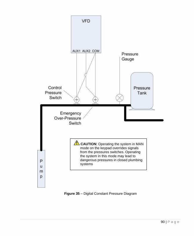
90 | P a g e
Figure 35 – Digital Constant Pressure Diagram
CAUTION: Operating the system in MAN mode on the keypad overrides signals from the pressures switches. Operating the system in this mode may lead to dangerous pressures in closed plumbing systems
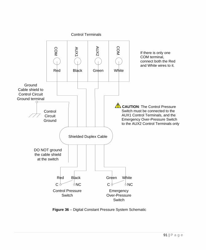
91 | P a g e
Figure 36 – Digital Constant Pressure System Schematic
CAUTION: The Control Pressure Switch must be connected to the AUX1 Control Terminals, and the Emergency Over-Pressure Switch to the AUX2 Control Terminals only
Control Pressure
Switch
AU
X1
AU
X2
CO
M
CO
M
Shielded Duplex Cable
Emergency
Over-Pressure
Switch
Control
Circuit
Ground
Control Terminals
DO NOT ground
the cable shield
at the switch
C CNC NC
Ground
Cable shield to
Control Circuit
Ground terminal
Red Black
Green
White
Red Black
Green
White
If there is only one COM terminal, connect both the Red and White wires to it.
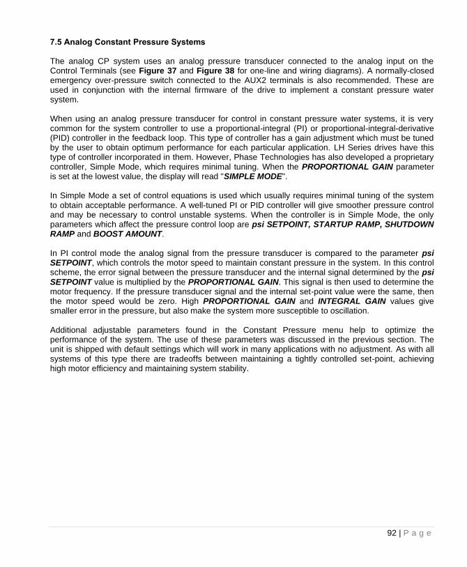
92 | P a g e
7.5 Analog Constant Pressure Systems The analog CP system uses an analog pressure transducer connected to the analog input on the Control Terminals (see Figure 37 and Figure 38 for one-line and wiring diagrams). A normally-closed emergency over-pressure switch connected to the AUX2 terminals is also recommended. These are used in conjunction with the internal firmware of the drive to implement a constant pressure water system. When using an analog pressure transducer for control in constant pressure water systems, it is very common for the system controller to use a proportional-integral (PI) or proportional-integral-derivative (PID) controller in the feedback loop. This type of controller has a gain adjustment which must be tuned by the user to obtain optimum performance for each particular application. LH Series drives have this type of controller incorporated in them. However, Phase Technologies has also developed a proprietary controller, Simple Mode, which requires minimal tuning. When the PROPORTIONAL GAIN parameter is set at the lowest value, the display will read "SIMPLE MODE". In Simple Mode a set of control equations is used which usually requires minimal tuning of the system to obtain acceptable performance. A well-tuned PI or PID controller will give smoother pressure control and may be necessary to control unstable systems. When the controller is in Simple Mode, the only parameters which affect the pressure control loop are psi SETPOINT, STARTUP RAMP, SHUTDOWN RAMP and BOOST AMOUNT. In PI control mode the analog signal from the pressure transducer is compared to the parameter psi SETPOINT, which controls the motor speed to maintain constant pressure in the system. In this control scheme, the error signal between the pressure transducer and the internal signal determined by the psi SETPOINT value is multiplied by the PROPORTIONAL GAIN. This signal is then used to determine the motor frequency. If the pressure transducer signal and the internal set-point value were the same, then the motor speed would be zero. High PROPORTIONAL GAIN and INTEGRAL GAIN values give smaller error in the pressure, but also make the system more susceptible to oscillation. Additional adjustable parameters found in the Constant Pressure menu help to optimize the performance of the system. The use of these parameters was discussed in the previous section. The unit is shipped with default settings which will work in many applications with no adjustment. As with all systems of this type there are tradeoffs between maintaining a tightly controlled set-point, achieving high motor efficiency and maintaining system stability.
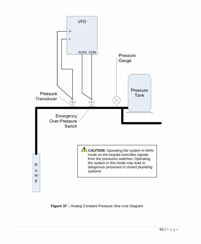
93 | P a g e
Figure 37 – Analog Constant Pressure One-Line Diagram
CAUTION: Operating the system in MAN mode on the keypad overrides signals from the pressures switches. Operating the system in this mode may lead to dangerous pressures in closed plumbing systems
94 | P a g e
Basic Analog Constant Pressure Installation Procedures:
1. Install the analog pressure transducer and emergency over-pressure switch in the water line 2. Remove protective rubber boot from the over-pressure switch, insert factory provided duplex
cable through the boot, and connect a twisted pair of wires to the normally closed (NC) and common (C) terminals of the switch
CAUTION: The use of shielded cable is recommended. Regular wire may induce capacitance in the line and corrupt the signals from the pressure switches.
3. Attach the cable shield to the Control Terminal Ground post located in the drive enclosure
adjacent to the Control Terminals 4. Connect the emergency over-pressure limit switch to the AUX2 Control Terminal and COM
(common). Use a jumper wire to connect AUX2 and COM if no limit switch is present. Also jumper AUX1 to COM if no external switch is connected to it.
5. Navigate through the keypad Main Menu item CHANGE PARAMETER VALUES > INTERFACE PARAMETERS > SYSTEM CONFIG. Select 2 to set the system configuration for an analog CP system (see Table 20 for details)
6. To set the emergency over-pressure limit switch, remove the rubber boot from the switch and pry the plastic plug from the top of the switch housing to access the pressure adjustment screw. Use an Allen wrench to adjust the pressure setting of the switch – jumper the AUX1 terminals and run the pump in the AUTO mode, and observe the pressure gauge, turning the Allen screw to adjust the pressure shut-off point. The emergency over-pressure limit switch should be set at least 10 PSI higher than the desired constant pressure set point.
7. Connect the remaining twisted pair of wires to the + and – terminals of the transducer 8. Connect the positive terminal of the transducer to the I_1+ Control Terminal, and the negative
terminal to the I_1- Control Terminal. 9. If a redundant analog transducer is used, connect it to the I_2+ and I_2- Terminals in likewise
fashion. See Section 6.4, System Configuration, for instructions on using an additional analog sensor.
CAUTION: It is critical that the positive terminal of the transducer is connected to the + terminal of the 4-20mA Control Terminal, and likewise for the negative terminals.
10. Set the psi SETPOINT on the keypad (see Table 20 for details) 11. Set the keypad to AUTO mode to operate the system
95 | P a g e
Figure 38 – Analog Constant Pressure System Schematic
AU
X2
I in +
I in -
CO
M
Shielded Duplex Cable
Emergency
Over-Pressure
Switch
Control
Circuit
Ground
Control Terminals
DO NOT ground
the cable shield
at the switch
C NC
Ground
Cable shield to
Control Circuit
Ground terminal
Green White
Black
Red
Green White
Black
Red
Analog
Pressure Transducer
- +
96 | P a g e
7.6 Pre-Charge Mode When filling a large plumbing system with water, it may be desirable to fill at a slow pump speed so that when the system reaches the full point, water hammer does not cause damage such as sprinkler head blow-off or burst pipes. To achieve this, LH drives are equipped with a pre-charge feature. Both the digital and analog constant pressure systems can implement a low-flow pre-charge of the system plumbing before the pump is allowed to come to full speed. This feature is disabled if the PRECHARGE TIME parameter is set to zero. For both types of CP systems, the frequency of the pump will not exceed the value set by the PRECHARGE FREQUENCY parameter during the pre-charge interval. In a digital CP system the pre-charge interval is terminated if either the PRECHARGE TIME is exceeded or the control pressure is reached. An analog CP system has the same features with the added option that the pre-charge interval will terminate when the system pressure exceeds the setting of the PRECHARGE psi parameter. In this case, the PRECHARGE psi must be lower than the psi SETPOINT. In both CP systems the pre-charge interval occurs whenever the drive is switched from OFF to AUTO or MANUAL > RUN. Pre-charge Mode Setup:
1. Navigate through the keypad menu to CHANGE PARAMETER VALUES > CONSTANT PRESSURE PARAMETERS > PRECHARGE FREQUENCY Enter the Pre-charge frequency
2. Navigate through the keypad menu to CHANGE PARAMETER VALUES > CONSTANT PRESSURE PARAMETERS > PRECHARGE TIME. Enter the Pre-charge time in seconds
3. For analog CP systems only, navigate through the keypad menu to CHANGE PARAMETER VALUES > CONSTANT PRESSURE PARAMETERS > PRECHARGE psi. Enter the pre-charge pressure in psi. This value must be lower than the psi SETPOINT
4. Set the keypad to AUTO mode to operate the system
97 | P a g e
7.7 Lead/Lag Pump Control When any analog constant pressure system configuration is selected, the LEAD/LAG menu is available. See Table 23, Lead/Lag Parameters, for lead/lag control options. Up to four additional pumps can be controlled through programmable relays on the main control printed circuit board. When the parameter NUMBER LAG PUMPS is greater than 0, all four relays will convert to control of lead/lag constant pressure.
CAUTION: Activation of lead/lag control overrides the function of all programmable relays. Any function of these relays set up through the Interface Parameters (Table 21) will be disabled. Lead/lag control in pumping systems is a common practice to maintain pressure with highly variable flow. The system is typically configured with a master pump controlled by a VFD operating in constant pressure mode, and with auxiliary pumps that are controlled by the drive. The auxiliary pumps typically operate across-the-line at 60 Hz. They may be equipped with a soft starter to mitigate inrush currents. If the master pump cannot maintain system pressure it will call for an auxiliary pump by closing a relay on the Control Terminals. LH Series drives can control up to four auxiliary pumps. There are features to reduce oscillations and ensure smooth staging and de-staging pumps. Lead/Lag Set-up System Configuration must be set to one of the constant pressure modes when using lead/lag control. See Section 6.4, System Configuration for details. Lead/lag control is enabled when the number of lag pumps is set to a value greater than zero in the parameter NUMBER LAG PUMPS. Programming Steps:
1. Use the keypad to navigate to the Main Menu item, CHANGE PARAMETER VALUES, then to sub-menu LEAD LAG PUMP PARAMETERS. Find the parameter NUMBER LAG PUMPS and use the arrow keys to set the number of auxiliary pumps in the system.
2. If necessary, adjust the remaining Lead/Lag parameters after reading the following description of their functions, or after operating conditions dictate.
Lag pumps are turned on and off, or “staged” and “de-staged”, by programmable relays accessed through the Control Terminals. The drive calls for lag pumps in ascending order, beginning with Relay 1. See Figure 39, Programmable Relays for Lead/Lag Control, to locate the relays. Figure 40, Lead/Lag Schematic, provides a wiring diagram. Lead/lag parameters (Table 23) are used to smoothly stage the pumps in and out, mitigating pressure oscillation, short cycling and water hammer. When the master pump cannot maintain pressure, the drive will stage in an auxiliary pump. The drive will de-stage the pump when flow increases pressure beyond the control point.
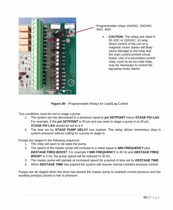
98 | P a g e
Figure 39 – Programmable Relays for Lead/Lag Control
Two conditions must be met to stage a pump:
1. The system psi has decreased to a pressure equal to psi SETPOINT minus STAGE PSI LAG.
For example, if the psi SETPOINT is 50 psi and you want to stage a pump in at 45 psi,
STAGE PSI LAG should be set to a 5.
2. The time set by STAGE PUMP DELAY has expired. This delay allows momentary drop in system pressure without calling for a pump to stage in.
Pumps are staged in the following sequence:
1. The relay will open to de-state the pump.
2. The speed of the master pump will increase to a value equal to MIN FREQUENCY plus
DESTAGE FREQ BOOST. For example if MIN FREQUENCY is 30 Hz and DESTAGE FREQ
BOOST is 5 Hz, the pump speed will be reduced to 35 Hz.
3. The master pump will operate at increased speed for a period of time set by DESTAGE TIME.
4. When DESTAGE TIME has expired the system will resume normal constant pressure control.
Pumps are de-staged when the drive has slowed the master pump to maintain control pressure and the auxiliary pump(s) causes a rise in pressure.
Programmable relays 1NO/NC, 2NO/NC, 3NO, 4NO.
• CAUTION: The relays are rated 0-30 VDC or 120VAC, 10 amp. Direct control of the coil on a magnetic motor starter will likely cause damage to the relay and the main control printed circuit board. Use of a secondary control relay, such as an ice cube relay, may be necessary to control the lag pump motor starter.
99 | P a g e
Three conditions must be met to de-stage a pump:
1. The system psi has increased to the value set by DESTAGE PSI LAG above psi SETPOINT.
For example, if psi SETPOINT is 50 and DESTAGE PSI LAG is 5 the pump will de-stage at 55
psi.
2. The time set by DESTAGE PUMP DELAY has expired. This delay prevents de-staging the
auxiliary pump due to momentary pressure overshoot.
3. The drive frequency to the master pump is between MIN FREQUENCY and the value of
DESTAGE MIN FREQ plus MIN FREQUENCY. For example, if MIN FREQUENCY is 30 Hz
and DESTAGE MIN FREQ is 5 Hz, the pump will de-stage at 35 Hz.
Pumps are de-staged in the following sequence: 1. The system pressure will increase by the value set by DESTAGE FRQ BOOST. This boost in
pressure allows the PI constant pressure loop to react faster to the drop in pressure when the
pump turns off.
2. The system will de-stage the pump
3. The system will continue to boost the pressure set by DESTAGE FRQ BOOST for a period of
time set by DESTAGE TIME.
4. The system will resume normal constant pressure control.
Pre-charge Pumps Feature In some systems the primary pump may not have the capacity to pre-charge the system on its own. The PRECHARGE PUMPS parameter will set the number of auxiliary pumps that will be called on to pump during the pre-charge interval. When the pre-charge interval is terminated, normal lead/lag control of the pumps will resume.
CAUTION: This number should never be greater that the total number of lag pumps as it will activate the associated programmable relay which may be reserved for other functions.
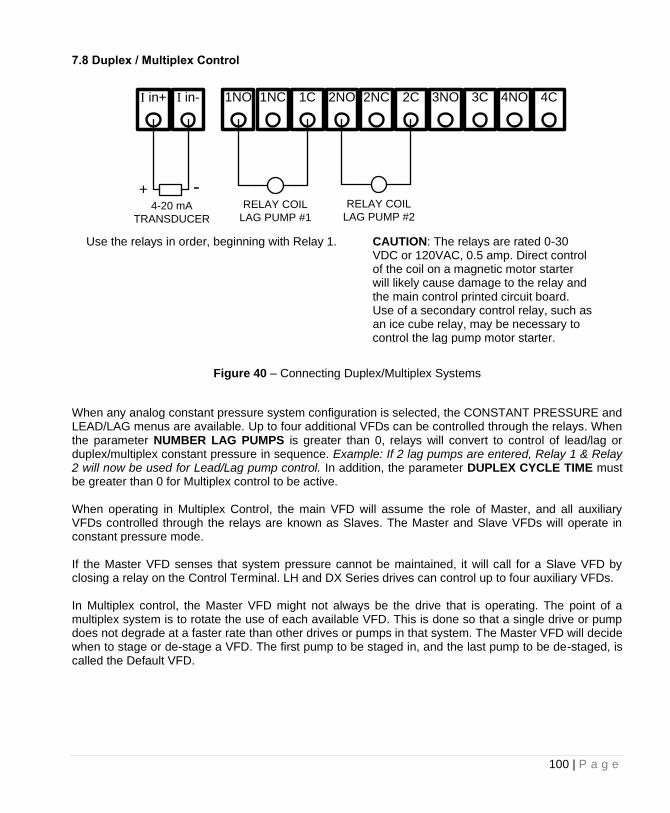
100 | P a g e
7.8 Duplex / Multiplex Control
Figure 40 – Connecting Duplex/Multiplex Systems
When any analog constant pressure system configuration is selected, the CONSTANT PRESSURE and LEAD/LAG menus are available. Up to four additional VFDs can be controlled through the relays. When the parameter NUMBER LAG PUMPS is greater than 0, relays will convert to control of lead/lag or duplex/multiplex constant pressure in sequence. Example: If 2 lag pumps are entered, Relay 1 & Relay 2 will now be used for Lead/Lag pump control. In addition, the parameter DUPLEX CYCLE TIME must be greater than 0 for Multiplex control to be active. When operating in Multiplex Control, the main VFD will assume the role of Master, and all auxiliary VFDs controlled through the relays are known as Slaves. The Master and Slave VFDs will operate in constant pressure mode. If the Master VFD senses that system pressure cannot be maintained, it will call for a Slave VFD by closing a relay on the Control Terminal. LH and DX Series drives can control up to four auxiliary VFDs. In Multiplex control, the Master VFD might not always be the drive that is operating. The point of a multiplex system is to rotate the use of each available VFD. This is done so that a single drive or pump does not degrade at a faster rate than other drives or pumps in that system. The Master VFD will decide when to stage or de-stage a VFD. The first pump to be staged in, and the last pump to be de-staged, is called the Default VFD.
Use the relays in order, beginning with Relay 1. CAUTION: The relays are rated 0-30 VDC or 120VAC, 0.5 amp. Direct control of the coil on a magnetic motor starter will likely cause damage to the relay and the main control printed circuit board. Use of a secondary control relay, such as an ice cube relay, may be necessary to control the lag pump motor starter.
I in-I in+ 1NO
+4-20 mA
TRANSDUCER
-
2C1C1NC 2NO 2NC 3NO 3C 4NO 4C
RELAY COIL
LAG PUMP #1
RELAY COIL
LAG PUMP #2
101 | P a g e
Multiplex Setup System configuration must be set to one of the constant pressure modes when using multiplex control. See Section 6.4, System Configuration, for details. Multiplex control is enabled when NUMBER LAG PUMPS is greater than 0, and DUPLEX CYCLE TIME is greater than 0. Programming Steps:
1. Use the keypad to navigate to the Main Menu item, CHANGE PARAMETER VALUES, then to sub-menu LEAD LAG PUMP PARAMETERS. Find the parameter NUMBER LAG PUMPS and use the arrow keys to set the number of auxiliary drives in the system.
2. Navigate to CONSTANT PRESSURE PARAMETERS, and find the parameter DUPLEX CYCLE TIME and use the arrow keys to set how often the Default drive position will change.
3. If necessary, adjust the remaining Lead/Lag parameters after reading the following description of their functions, or after operating conditions dictate.
In Multiplex control, the Master VFD will utilize the Lead/Lag Parameters and logic similar to lead/lag control in order to decide when to turn on/off a VFD. More detail on the logic behind these decisions will be given in a later section.
It is recommended to run all auxiliary pumps on VFDs, otherwise pressure instability may occur. The Primary Auxiliary Pump could turn on/off resulting in the system pressure oscillating from (psi SETPOINT – STAGE PSI LAG) to (psi SETPOINT + DESTAGE PSI LAG). The Master VFD stages in VFDs in a different order depending on which VFD is the Primary. When the Master VFD is not the Primary, it will ALWAYS be the second drive to be staged in. The tables below will illustrate the order of the VFDs to be staged or de-staged for different values of NUMBER LAG PUMPS. The Primary drive position will rotate based on the parameter DUPLEX CYCLE TIME.
Master + 1 Slave VFD
Rotation Primary Drive VFD Order
1st Rotation Master M <=> 1
2nd Rotation Slave VFD 1 1 <=> M
Master + 2 Slave VFD
Rotation Primary Drive VFD Order
1st Rotation Master M <=> 1 <=> 2
2nd Rotation Slave VFD 1 1 <=> M <=>> 2
3rd Rotation Slave VFD 2 2 <=> M <=> 1
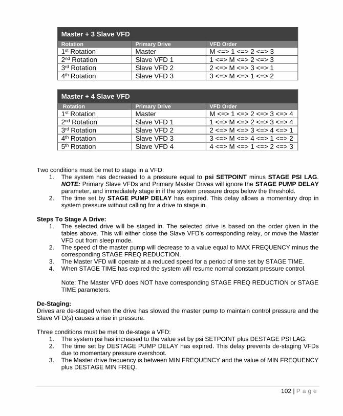
102 | P a g e
Master + 3 Slave VFD
Rotation Primary Drive VFD Order
1st Rotation Master M <=> 1 <=> 2 <=> 3
2nd Rotation Slave VFD 1 1 <=> M <=> 2 <=> 3
3rd Rotation Slave VFD 2 2 <=> M <=> 3 <=> 1
4th Rotation Slave VFD 3 3 <=> M <=> 1 <=> 2
Two conditions must be met to stage in a VFD:
1. The system has decreased to a pressure equal to psi SETPOINT minus STAGE PSI LAG. NOTE: Primary Slave VFDs and Primary Master Drives will ignore the STAGE PUMP DELAY parameter, and immediately stage in if the system pressure drops below the threshold.
2. The time set by STAGE PUMP DELAY has expired. This delay allows a momentary drop in system pressure without calling for a drive to stage in.
Steps To Stage A Drive:
1. The selected drive will be staged in. The selected drive is based on the order given in the tables above. This will either close the Slave VFD’s corresponding relay, or move the Master VFD out from sleep mode.
2. The speed of the master pump will decrease to a value equal to MAX FREQUENCY minus the corresponding STAGE FREQ REDUCTION.
3. The Master VFD will operate at a reduced speed for a period of time set by STAGE TIME. 4. When STAGE TIME has expired the system will resume normal constant pressure control.
Note: The Master VFD does NOT have corresponding STAGE FREQ REDUCTION or STAGE TIME parameters.
De-Staging: Drives are de-staged when the drive has slowed the master pump to maintain control pressure and the Slave VFD(s) causes a rise in pressure. Three conditions must be met to de-stage a VFD:
1. The system psi has increased to the value set by psi SETPOINT plus DESTAGE PSI LAG. 2. The time set by DESTAGE PUMP DELAY has expired. This delay prevents de-staging VFDs
due to momentary pressure overshoot. 3. The Master drive frequency is between MIN FREQUENCY and the value of MIN FREQUENCY
plus DESTAGE MIN FREQ.
Master + 4 Slave VFD
Rotation Primary Drive VFD Order
1st Rotation Master M <=> 1 <=> 2 <=> 3 <=> 4
2nd Rotation Slave VFD 1 1 <=> M <=> 2 <=> 3 <=> 4
3rd Rotation Slave VFD 2 2 <=> M <=> 3 <=> 4 <=> 1
4th Rotation Slave VFD 3 3 <=> M <=> 4 <=> 1 <=> 2
5th Rotation Slave VFD 4 4 <=> M <=> 1 <=> 2 <=> 3
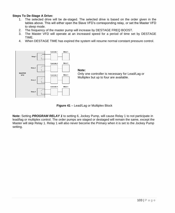
103 | P a g e
Steps To De-Stage A Drive: 1. The selected drive will be de-staged. The selected drive is based on the order given in the
tables above. This will either open the Slave VFD’s corresponding relay, or set the Master VFD to sleep mode.
2. The frequency of the master pump will increase by DESTAGE FREQ BOOST. 3. The Master VFD will operate at an increased speed for a period of time set by DESTAGE
TIME. 4. When DESTAGE TIME has expired the system will resume normal constant pressure control.
Figure 41 – Lead/Lag or Multiplex Block
Note: Setting PROGRAM RELAY 1 to setting 6, Jockey Pump, will cause Relay 1 to not participate in lead/lag or multiplex control. The order pumps are staged or destaged will remain the same, except the Master will skip Relay 1. Relay 1 will also never become the Primary when it is set to the Jockey Pump setting.
Note: Only one controller is necessary for Lead/Lag or Multiplex but up to four are available.
104 | P a g e
TROUBLESHOOTING This section provides information on fault codes and troubleshooting tips for potential system problems.
WARNING! In some instances, the unit will shut down, then automatically restart when conditions allow. Always disconnect input power from the unit and wait for internal electrical charges to dissipate before performing service on the unit or its connected loads.
WARNING: Risk of electric shock. De-energize the unit by disconnecting all incoming sources of
power, then wait 5 minutes for internal charges to dissipate before servicing the equipment.
HIGH VOLTAGE: This equipment is connected to line voltages that can create a potentially hazardous situation. Electric shock could result in serious injury or death. This device should be installed and serviced only by trained, licensed and qualified personnel. Follow instructions carefully and observe all warnings.
Always check the display for fault codes if the drive or its load is not operating. Disconnecting the input power could potentially clear any fault code indication, possibly losing valuable information for troubleshooting. 8.1 Fault Codes Fault codes are indicated on the graphic display. See Table 26, on page 106, for a list of fault codes. The drive can be programmed to automatically restart after certain faults and a time delay can be programmed before the restart is allowed. To interrupt a time delay countdown and allow auto restart, press both arrow keys on the keypad and hold for one second. The load will start immediately. The Restart Log is a resettable fault log that can be used to monitor faults that allow auto restart. Use the Clear Memory function to reset the Restart Log and set all fault counters to zero. See Section 4.2, Keypad Main Menu Items, for more information on Restart Log and Clear Memory function.
WARNING: Certain faults do not allow an auto restart. These faults generally indicate the possibility of damage to the drive and/or the load, or indicate the possibility of a dangerous condition. When this type fault occurs, the display will read NO AUTO RESTART. Refer to Table 8-1, Fault Codes, to determine if the fault allows an auto restart. The number 1 in the notes column indicates that auto restart is not allowed. When this type fault occurs, contact the factory for assistance before restarting or troubleshoot the system thoroughly. These faults can be cleared only by cycling input power OFF/ON or by pressing both arrow keys for 3 seconds.
WARNING: Unit may restart automatically without warning after a fault when operating conditions permit. Make certain input power is disconnected before servicing the unit or its connected loads.
105 | P a g e
8.2 Clearing a Fault If the unit is programmed to automatically restart after a particular fault, the display indicates that the unit will restart and will count down the seconds remaining to restart on the display. The countdown can be interrupted by pressing and holding both arrow keys. The load will immediately restart. For faults that allow an automatic restart, the default number of restarts after a fault is zero. If the end user desires the unit to automatically restart after a fault, the number of restarts allowed and the time between fault and restart must be programmed in the CHANGE PARAMETER VALUES > AUTO RESTART PARAMETERS for that fault. If the drive has exceeded the programmed number of auto restarts, or if auto restarts have not been enabled, the display will indicate the fault on the top line and the second line will read RESTART? ENTER. Press ENTER to clear the fault and restart the load. The fault counters in the Restart Log will all be reset to zero. See Section 4.6, Restart Log, for more information. The ENABLE RESTART parameter allows the drive to restart automatically after a fault. This parameter also enables to drive to initialize in AUTO mode when the input power has been cycled OFF/ON and the drive is energized. The factory default setting does not allow auto restarts. Navigate to this parameter via CHANGE PARAMETER VALUES > AUTO RESTART PARAMETERS > ENABLE RESTART. See Table 22 for values in setting the parameter. Certain faults do not allow an auto restart. These faults generally indicate the possibility of damage to the drive and/or the load, or indicate the possibility of a dangerous condition. When this type fault occurs, the display will read NO AUTO RESTART. When this type fault occurs, contact the factory for assistance before restarting or troubleshoot the system thoroughly. These faults can be cleared only by cycling input power OFF/ON or by pressing both arrow keys for 3 seconds. There are several conditions where the drive will indicate a fault but the fault will not be recorded in the fault log. These faults occur only when the drive is energized from utility mains and is initializing. If any condition including ground fault, pre-charge fail, high input voltage or low input voltage is detected, the display will indicate the fault and wait for the condition to resolve before entering normal operating mode. If these conditions occur after the drive has initialized, a fault will be logged and can be cleared in the normal manner.
WARNING: The drive may start automatically without warning when operating conditions permit. Make certain input power is disconnected before servicing the unit or its connected loads.
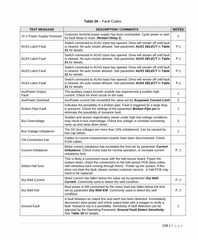
106 | P a g e
Table 26 – Fault Codes
TEXT MESSAGE DESCRIPTION / COMMENTS NOTES
15 V Power Supply Overload Customer terminal power supply has been overloaded. Cycle power or wait for fault delay to reset. (Restart Delay 2)
1
AUX1 Latch Fault Switch connected to AUX1 input has opened. Drive will remain off until fault is cleared. No auto restart allowed. See parameter AUX1 SELECT in Table 21 for details.
P,1
AUX2 Latch Fault Switch connected to AUX2 input has opened. Drive will remain off until fault is cleared. No auto restart allowed. See parameter AUX2 SELECT in Table 21 for details.
P,1
AUX3 Latch Fault Switch connected to AUX3 input has opened. Drive will remain off until fault is cleared. No auto restart allowed. See parameter AUX3 SELECT in Table 21 for details.
P,1
AUX4 Latch Fault Switch connected to AUX4 input has opened. Drive will remain off until fault is cleared. No auto restart allowed. See parameter AUX4 SELECT in Table 21 for details.
P,1
AuxPower Output Fault
The auxiliary output inverter module has experienced a sudden high current. Check for short circuit on the load.
1
AuxPower Overload AuxPower current has exceeded the value set by Auxpower Current Limit 2
Broken Pipe Fault Indicates the possibility of a broken pipe. Fault is triggered by a large drop in pressure. Check the settings of the parameter Broken Pipe psi to eliminate the possibility of nuisance fault.
1
Bus Overvoltage Sudden and severe regenerative power under high line voltage conditions may result in bus overvoltage. Check line voltage or consider increasing ramp up and ramp down times.
2
Bus Voltage Unbalance The DC bus voltages are more than 10% unbalanced. Can be caused by bus cap failure.
1
CM Connection Fail Cables to current measurement boards have been disconnected. Check RJ45 cables.
Current Unbalance Motor current unbalance has exceeded the limit set by parameter Current Unbalance. Check motor load for normal operation, or increase current unbalance limit.
P, 2
Defect Hall Snsr
This is likely a connection issue with the hall sensor board. Power the system down, check the connections to the hall sensor PCB (blue cubes with wires/bus bars running through them). Power up the system. If this does not clear the fault, please contact customer service. A Hall PCB may need to be replaced.
Dry Well Current Motor current has fallen below the value set by parameter Dry Well Current. Commonly used to detect dry well condition.
P, 2
Dry Well KW Real power in kW consumed by the motor load has fallen below the limit set by parameter Dry Well KW. Commonly used to detect dry well condition.
P, 2
Ground Fault
A fault between an output line and earth has been detected. Immediately disconnect input power and check output lines with a megger to verify a fault. Nuisance trip is a possibility. Sensitivity of fault detection can be adjusted by the Operating Parameter Ground Fault Detect Sensitivity. See Table 19 for details.
1
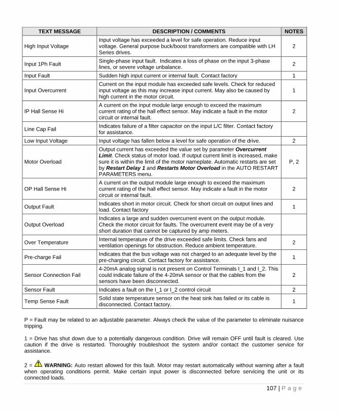
107 | P a g e
TEXT MESSAGE DESCRIPTION / COMMENTS NOTES
High Input Voltage Input voltage has exceeded a level for safe operation. Reduce input voltage. General purpose buck/boost transformers are compatible with LH Series drives.
2
Input 1Ph Fault Single-phase input fault. Indicates a loss of phase on the input 3-phase lines, or severe voltage unbalance.
2
Input Fault Sudden high input current or internal fault. Contact factory 1
Input Overcurrent Current on the input module has exceeded safe levels. Check for reduced input voltage as this may increase input current. May also be caused by high current in the motor circuit.
1
IP Hall Sense Hi A current on the input module large enough to exceed the maximum current rating of the hall effect sensor. May indicate a fault in the motor circuit or internal fault.
2
Line Cap Fail Indicates failure of a filter capacitor on the input L/C filter. Contact factory for assistance.
Low Input Voltage Input voltage has fallen below a level for safe operation of the drive. 2
Motor Overload
Output current has exceeded the value set by parameter Overcurrent Limit. Check status of motor load. If output current limit is increased, make sure it is within the limit of the motor nameplate. Automatic restarts are set by Restart Delay 1 and Restarts Motor Overload in the AUTO RESTART PARAMETERS menu.
P, 2
OP Hall Sense Hi A current on the output module large enough to exceed the maximum current rating of the hall effect sensor. May indicate a fault in the motor circuit or internal fault.
2
Output Fault Indicates short in motor circuit. Check for short circuit on output lines and load. Contact factory
1
Output Overload Indicates a large and sudden overcurrent event on the output module. Check the motor circuit for faults. The overcurrent event may be of a very short duration that cannot be captured by amp meters.
Over Temperature Internal temperature of the drive exceeded safe limits. Check fans and ventilation openings for obstruction. Reduce ambient temperature.
2
Pre-charge Fail Indicates that the bus voltage was not charged to an adequate level by the pre-charging circuit. Contact factory for assistance.
1
Sensor Connection Fail 4-20mA analog signal is not present on Control Terminals I_1 and I_2. This could indicate failure of the 4-20mA sensor or that the cables from the sensors have been disconnected.
2
Sensor Fault Indicates a fault on the I_1 or I_2 control circuit 2
Temp Sense Fault Solid state temperature sensor on the heat sink has failed or its cable is disconnected. Contact factory.
1
P = Fault may be related to an adjustable parameter. Always check the value of the parameter to eliminate nuisance tripping. 1 = Drive has shut down due to a potentially dangerous condition. Drive will remain OFF until fault is cleared. Use caution if the drive is restarted. Thoroughly troubleshoot the system and/or contact the customer service for assistance.
2 = WARNING: Auto restart allowed for this fault. Motor may restart automatically without warning after a fault when operating conditions permit. Make certain input power is disconnected before servicing the unit or its connected loads.
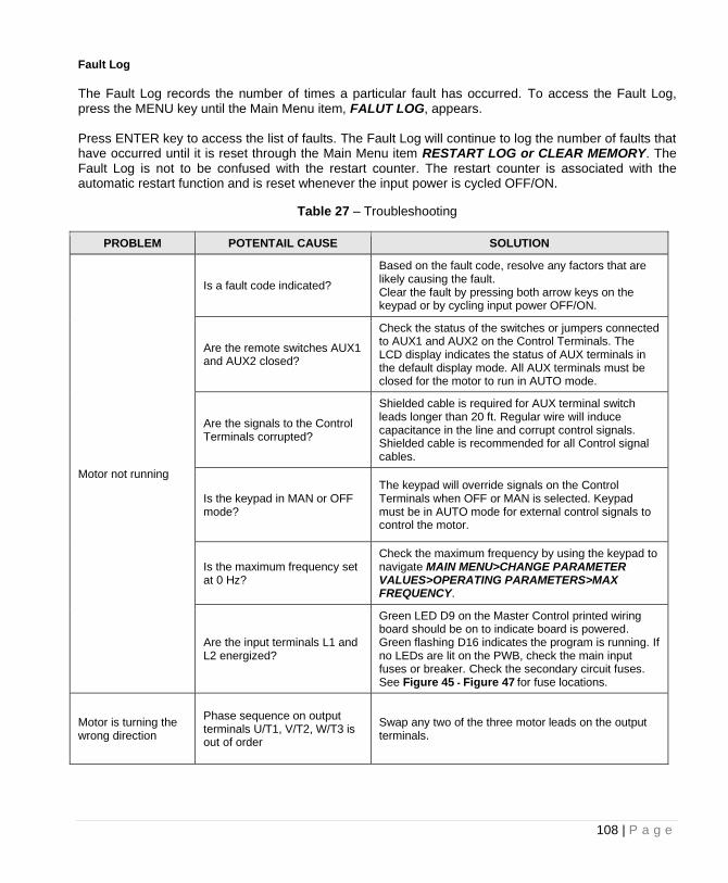
108 | P a g e
Fault Log
The Fault Log records the number of times a particular fault has occurred. To access the Fault Log, press the MENU key until the Main Menu item, FALUT LOG, appears. Press ENTER key to access the list of faults. The Fault Log will continue to log the number of faults that have occurred until it is reset through the Main Menu item RESTART LOG or CLEAR MEMORY. The Fault Log is not to be confused with the restart counter. The restart counter is associated with the automatic restart function and is reset whenever the input power is cycled OFF/ON.
Table 27 – Troubleshooting
PROBLEM POTENTAIL CAUSE SOLUTION
Motor not running
Is a fault code indicated?
Based on the fault code, resolve any factors that are likely causing the fault. Clear the fault by pressing both arrow keys on the keypad or by cycling input power OFF/ON.
Are the remote switches AUX1 and AUX2 closed?
Check the status of the switches or jumpers connected to AUX1 and AUX2 on the Control Terminals. The LCD display indicates the status of AUX terminals in the default display mode. All AUX terminals must be closed for the motor to run in AUTO mode.
Are the signals to the Control Terminals corrupted?
Shielded cable is required for AUX terminal switch leads longer than 20 ft. Regular wire will induce capacitance in the line and corrupt control signals. Shielded cable is recommended for all Control signal cables.
Is the keypad in MAN or OFF mode?
The keypad will override signals on the Control Terminals when OFF or MAN is selected. Keypad must be in AUTO mode for external control signals to control the motor.
Is the maximum frequency set at 0 Hz?
Check the maximum frequency by using the keypad to navigate MAIN MENU>CHANGE PARAMETER VALUES>OPERATING PARAMETERS>MAX FREQUENCY.
Are the input terminals L1 and L2 energized?
Green LED D9 on the Master Control printed wiring board should be on to indicate board is powered. Green flashing D16 indicates the program is running. If no LEDs are lit on the PWB, check the main input fuses or breaker. Check the secondary circuit fuses. See Figure 45 - Figure 47 for fuse locations.
Motor is turning the wrong direction
Phase sequence on output terminals U/T1, V/T2, W/T3 is out of order
Swap any two of the three motor leads on the output terminals.
109 | P a g e
ROUTINE INSPECTION AND MAINTENANCE The unit should be inspected and cleaned at least annually or more frequently if it is located in an excessively warm or dusty environment. Power terminals: Inspect for loose connections and tighten to specifications in Table 11 and Table 12. Capacitors: Check for leakage or deformation. Overall: Perform a visual inspection checking for things such as discolored wires or terminals, evidence of arcing, loose mounting screws, physical damage to the enclosure, etc. Fans and heatsinks: Excessive dust buildup on the heatsink and cooling fan impellers may lead to overheating. Lightly brush and vacuum clean. Instructions for fan replacement: Contact Customer Service for assistance in replacing the cooling fan in the event it should fail. Use only fans approved by Phase Technologies. Unapproved fans may not be able to move enough air to properly cool the unit, leading to component damage. Line Filter Capacitors Line filter capacitors are part of the inductor/capacitor (L/C) filters that filter harmonics from either the input lines our output lines of the drive. While it is extremely rare for the inductor to fail, capacitors are inherently more prone to degradation and failure and should be routinely monitored and/or replaced. Failure of the L/C filter can lead to increased harmonic levels which may damage equipment connected to the drive.
CAUTION: Line Filter Capacitors Line filter capacitors should be inspected annually at a minimum. Replacement of the capacitors every three years is recommended as preventive maintenance. If they are degraded the electrical noise can damage equipment connected to the drive.
Line filter capacitors should be visually inspected and electrically tested on a routine basis. The capacitors are easily accessible. See Figure 42 – Line Filter Cap Location (Performance Series)and Figure 43 below to locate the line filter capacitors. Visually inspect the line filter capacitors and the wires connected to them for any discoloration and for bulges in the canister. Capacitors are connected in two different configurations, either line-to-line or line-to-ground. The The capacitors have electrical ratings in both voltage and capacitance measured as microfarads (uF). Drives equipped with optional AUX POWER™ have five line-to-ground capacitors, while models without the option have two. All models have line-to-line capacitors. Using a multi-meter set to measure capacitance, check the capacitance of each capacitor by measuring between the two terminals on the capacitor. Remove the wire from at least one terminal of the capacitor in order to obtain an accurate measurement. Compare to the capacitor value in Table 28 and Table 29. If any capacitor value is less than specified by more than 25% contact Phase Technologies customer support at 605-343-7934 to order replacement capacitors. If you do not have a
110 | P a g e
meter or other means to test the capacitors it is recommended to replace the capacitors every three years as a preventive measure. Do not operate the drive with degraded capacitors.
Table 28 – Line-to-Line Capacitors
Drive Model No. Capacitors Capacitor Value Phase Technologies PN
1LHE005 1 35 uF 480V AC0027
1LHE007 1 35 uF 480V AC0027
1LHE010 1 35 uF 480V AC0027
1LHE015 1 35 uF 480V AC0027
1LHE020 1 35 uF 480V AC0027
1LHE205 1 35 uF 480V AC0027
1LHE207 1 35 uF 480V AC0027
1LHE210 1 35 uF 480V AC0027
1LHE215 1 35 uF 480V AC0027
1LH220, 1LHS220, 1LHE220 1 35 uF 480V AC0027
1LHE225 1 35 uF 480V AC0027
1LH230, 1LHS230 1 35 uF 480V AC0027
1LH240, 1LHS240 2 35 uF 480V AC0027
1LH250 2 35 uF 480V AC0027
1LHE405 1 35 uF 480V AC0027
1LHE407 1 35 uF 480V AC0027
1LHE410 1 35 uF 480V AC0027
1LHE415 1 35 uF 480V AC0027
1LH420, 1LHS420, 1LHE420 1 35 uF 480V AC0027
1LHE425 1 35 uF 480V AC0027
1LH430, 1LHS430, 1LHE430 1 35 uF 480V AC0027
1LH440, 1LHS440 1 35 uF 480V AC0027
1LH450, 1LHS450 1 35 uF 480V AC0027
1LH460, 1LHS460 1 35 uF 480V AC0027
111 | P a g e
Drive Model No. Capacitors Capacitor Value Phase Technologies PN
1LH460-C 2 35 uF 480V AC0027
1LH475, 1LHS475 2 35 uF 480V AC0027
1LH4100, 1LHS4100 2 35 uF 480V AC0027
1LH4125 NA NA NA
3LHE005 1 10.5 uF 500V C00058
3LHE007 1 21 uF 500V C00059
3LHE010 1 21 uF 500V C00059
3LHE015 1 21 uF 500V C00059
3LHE020 1 21 uF 500V C00059
3LHE025 1 53 uF 500V C00061
3LHE030 1 53 uF 500V C00061
3LHE205 1 10.5 uF 500V C00058
3LHE207 1 10.5 uF 500V C00058
3LHE210 1 21 uF 500V C00059
3LHE215 1 21 uF 500V C00059
3LH220, 3LHS220, 3LHE220 1 21 uF 500V C00059
3LHE225 1 21 uF 500V C00059
3LH230, 3LHS230 1 53 uF 500V C00061
3LH240, 3LHS240 1 53 uF 500V C00061
3LH250, 3LHS250 1 64 uF 500V C00062
3LH260, 3LHS260 2 53 uF 500V C00061
3LHE405 1 10.5 uF 500V C00058
3LHE407 1 10.5 uF 500V C00058
3LHE410 1 10.5 uF 500V C00058
3LHE415 1 10.5 uF 500V C00058
3LH420, 3LHS420, 3LHE420 1 21 uF 500V C00059
3LHE425 1 21 uF 500V C00059
3LH430, 3LHS430, 3LHE430 1 21 uF 500V C00059
112 | P a g e
Drive Model No. Capacitors Capacitor Value Phase Technologies PN
3LH440, 3LHS440, 3LHE440 1 21 uF 500V C00059
3LH450, 3LHS450, 3LHE450 1 32 uF 500V C00060
3LH460, 3LHS460 1 53 uF 500V C00061
3LH475, 3LHS475 1 53 uF 500V C00061
3LH4100, 3LHS4100 1 64 uF 500V C00062
3LH4125, 3LHS4125 2 53 uF 500V C00061
3LH4150, 3LHS150 2 53 uF 500V C00061
3LH4200, 3LHS4200 2 64 uF 500V C00062
3LH4250 2 64 uF 500V C00062
3LH4300 2 64 uF 500V C00062
3LH4350 2 64 uF 500V C00062
3LH4400 2 64 uF 500V C00062
3LH4450 2 64 uF 500V C00062
All DX, DXS, & DXE Series NA NA NA
113 | P a g e
Table 29 - Line-to-Ground Capacitors
Drive Model No. Capacitors Capacitor Value Phase Technologies PN
1LH220, 1LHS220 2 0.47 uF, 1200V AC0033
1LH220C 2 0.47 uF, 1200V AC0033
1LH230, 1LHS230 2 0.47 uF, 1200V AC0033
1LH230C 2 0.47 uF, 1200V AC0032
1LH240, 1LHS240 2 0.47 uF, 1200V AC0032
1LH250 2 0.47 uF, 1200V AC0032
1LH420, 1LHS420 2 0.47 uF, 1200V AC0033
1LH420C 2 0.47 uF, 1200V AC0033
1LH430, 1LHS430 2 0.47 uF, 1200V AC0033
1LH430C 2 0.47 uF, 1200V AC0033
1LH440, 1LHS440 2 0.47 uF, 1200V AC0033
1LH440C 2 0.47 uF, 1200V AC0033
1LH450, 1LHS450 2 0.47 uF, 1200V AC0033
1LH450C 2 0.47 uF, 1200V AC0033
1LH460, 1LHS460 2 0.47 uF, 1200V AC0032
1LH460C 2 0.47 uF, 1200V AC0032
1LH475, 1LHS475 2 0.47 uF, 1200V AC0032
1LH475C 2 0.47 uF, 1200V AC0032
1LH4100, 1LHS4100 2 0.47 uF, 1200V AC0032
1LH4100C 2 0.47 uF, 1200V AC0032
1LH4125 NA NA NA
All 1LHE Series 2 0.47 uF, 1200V AC0133
All 3LH & 3LHS Series 3 0.47 uF, 1200V AC00134
All 3LHE Series 3 0.47 uF, 1200V AC00133
All DX, DXS, & DXE Series NA NA NA
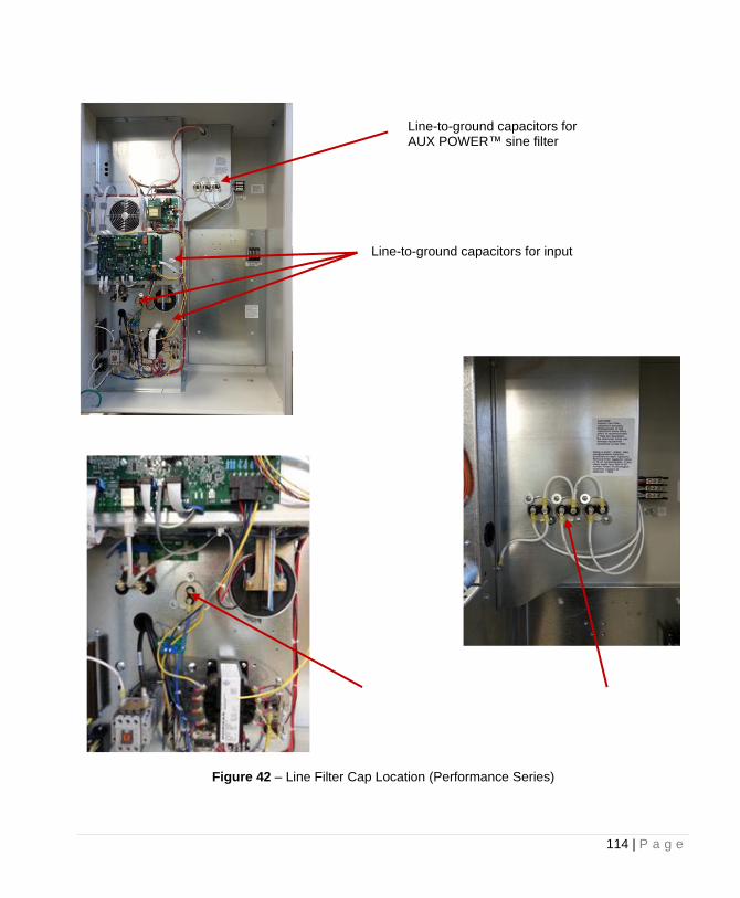
114 | P a g e
Figure 42 – Line Filter Cap Location (Performance Series)
Line-to-ground capacitors for AUX POWER™ sine filter
Line-to-ground capacitors for input
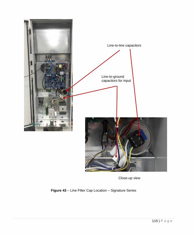
115 | P a g e
Figure 43 – Line Filter Cap Location – Signature Series
Line-to-line capacitors
Close-up view
Line-to-ground capacitors for input
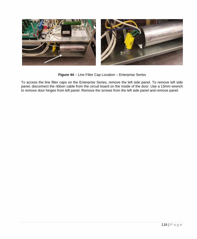
116 | P a g e
Figure 44 – Line Filter Cap Location – Enterprise Series
To access the line filter caps on the Enterprise Series, remove the left side panel. To remove left side panel, disconnect the ribbon cable from the circuit board on the inside of the door. Use a 13mm wrench to remove door hinges from left panel. Remove the screws from the left side panel and remove panel.
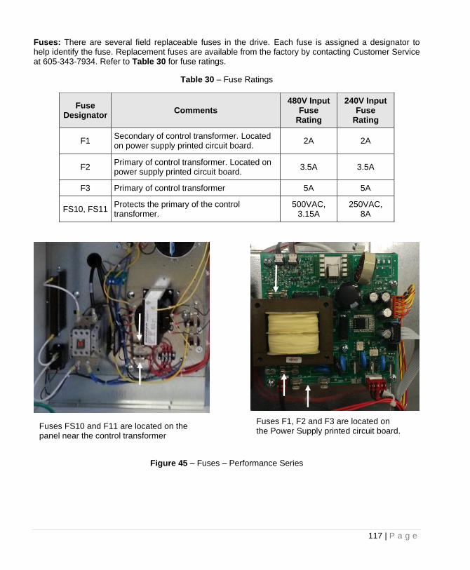
117 | P a g e
Fuses: There are several field replaceable fuses in the drive. Each fuse is assigned a designator to help identify the fuse. Replacement fuses are available from the factory by contacting Customer Service at 605-343-7934. Refer to Table 30 for fuse ratings.
Table 30 – Fuse Ratings
Fuse Designator
Comments 480V Input
Fuse Rating
240V Input Fuse
Rating
F1 Secondary of control transformer. Located on power supply printed circuit board.
2A 2A
F2 Primary of control transformer. Located on power supply printed circuit board.
3.5A 3.5A
F3 Primary of control transformer 5A 5A
FS10, FS11 Protects the primary of the control transformer.
500VAC, 3.15A
250VAC, 8A
Figure 45 – Fuses – Performance Series
Fuses FS10 and F11 are located on the panel near the control transformer
Fuses F1, F2 and F3 are located on the Power Supply printed circuit board.
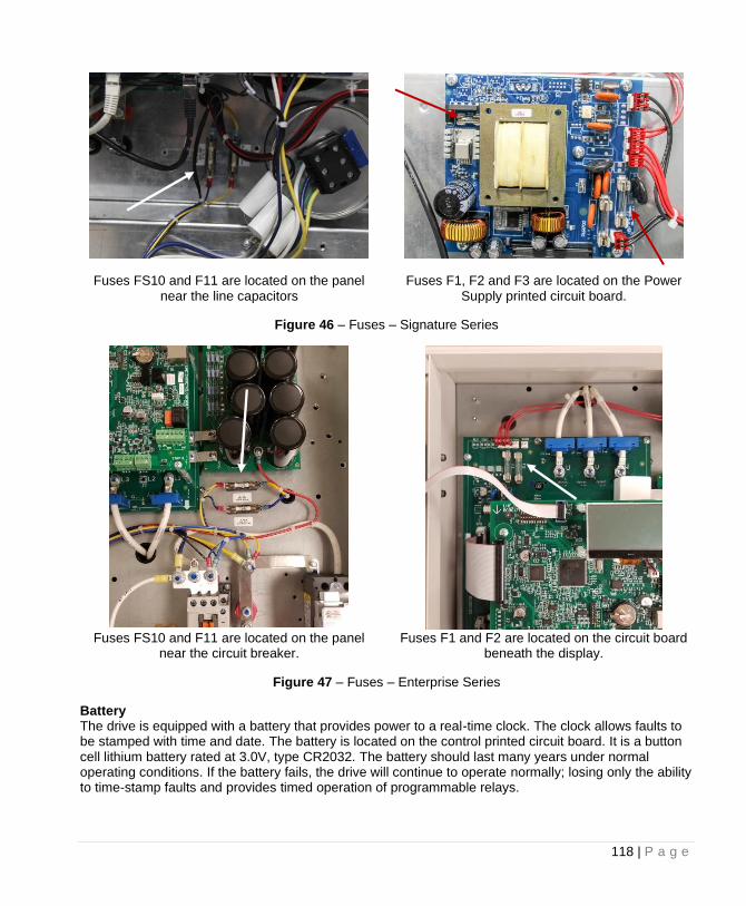
118 | P a g e
Fuses FS10 and F11 are located on the panel near the line capacitors
Fuses F1, F2 and F3 are located on the Power Supply printed circuit board.
Figure 46 – Fuses – Signature Series
Fuses FS10 and F11 are located on the panel
near the circuit breaker. Fuses F1 and F2 are located on the circuit board
beneath the display.
Figure 47 – Fuses – Enterprise Series
Battery The drive is equipped with a battery that provides power to a real-time clock. The clock allows faults to be stamped with time and date. The battery is located on the control printed circuit board. It is a button cell lithium battery rated at 3.0V, type CR2032. The battery should last many years under normal operating conditions. If the battery fails, the drive will continue to operate normally; losing only the ability to time-stamp faults and provides timed operation of programmable relays.

LIMITED WARRANTY
Phase Technologies’ 1LH, 3LH and DX Series drives are warranted against defects in material and workmanship for a period of two years. This warranty covers both parts and labor (at Phase Technologies) for two years from the date of purchase by the original owner. Phase Technologies will repair or replace (at our option), at no charge, any part(s) found to be faulty during the warranty period specified. The warranty repairs must be performed by/at a Phase Technologies Authorized Service Center or at Phase Technologies LLC, Rapid City, SD.
Obligations of the Original Owner 1. The original Bill of Sale must be presented in order to obtain “in-warranty” service. 2. Transportation to Phase Technologies or an Authorized Service Center is the
responsibility of the original purchaser. Return transportation is provided by Phase Technologies.
3. Installations must comply with all national and local electrical codes.
Exclusions of the Warranty
This warranty does not cover any of the following: accident, misuse, fire, flood, and other acts of God, nor any contingencies beyond the control of Phase Technologies, LLC, including water damage, incorrect line voltage, improper installation, missing or altered serial numbers, and service performed by an unauthorized facility. Phase Technologies’ liability for any damages caused in association with the use of Phase Technologies’ equipment shall be limited to the repair or replacement only of the Phase Technologies’ equipment. No person, agent, distributor, dealer, or company is authorized to modify, alter, or change the design of this merchandise without express written approval of Phase Technologies, LLC. INSTALLATIONS MUST COMPLY WITH ALL NATIONAL AND LOCAL ELECTRICAL
CODE REQUIREMENTS.

222 Disk Drive, Rapid City, SD 57701
605-343-7934 - Main 866-250-7934 - Toll Free
www.phasetechnologies.com
PHASET ECHNOLOG I E S