Embed Size (px)
Citation preview
Photoconductive Cells
1
What is a Photoconductive Cell?
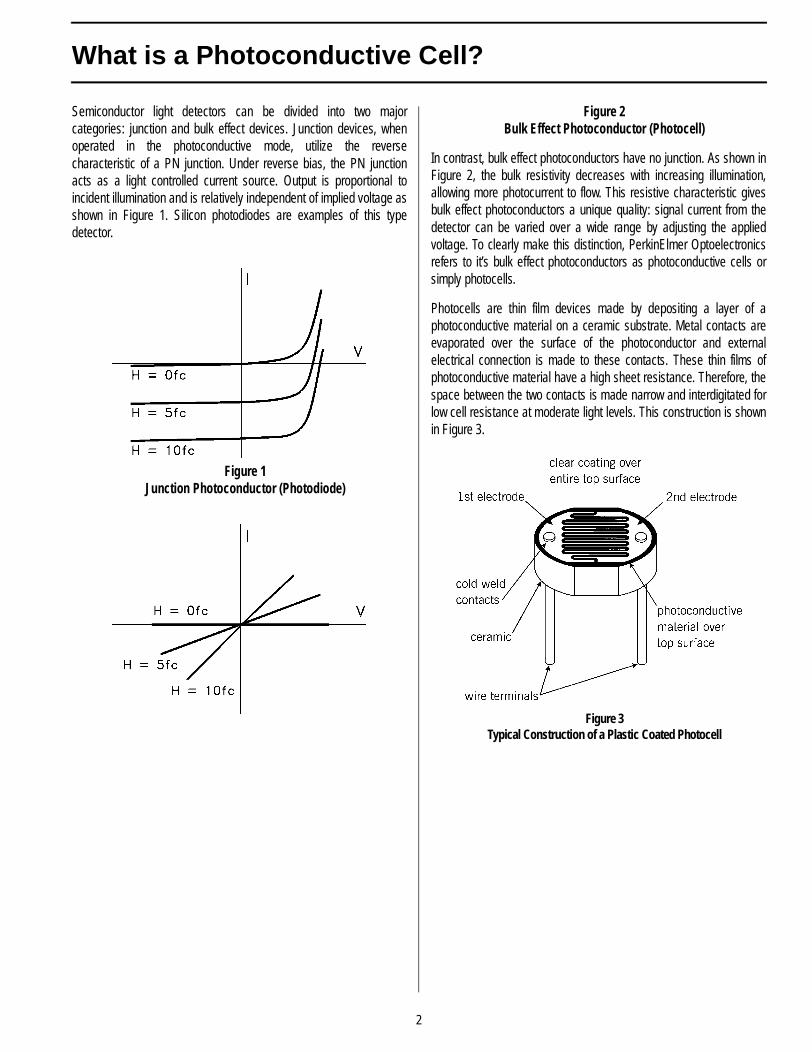
Semiconductor light detectors can be divided into two majorcategories: junction and bulk effect devices. Junction devices, whenoperated in the photoconductive mode, utilize the reversecharacteristic of a PN junction. Under reverse bias, the PN junctionacts as a light controlled current source. Output is proportional toincident illumination and is relatively independent of implied voltage asshown in Figure 1. Silicon photodiodes are examples of this typedetector.
Figure 1Junction Photoconductor (Photodiode)
Figure 2Bulk Effect Photoconductor (Photocell)
In contrast, bulk effect photoconductors have no junction. As shown inFigure 2, the bulk resistivity decreases with increasing illumination,allowing more photocurrent to flow. This resistive characteristic givesbulk effect photoconductors a unique quality: signal current from thedetector can be varied over a wide range by adjusting the appliedvoltage. To clearly make this distinction, PerkinElmer Optoelectronicsrefers to it’s bulk effect photoconductors as photoconductive cells orsimply photocells.
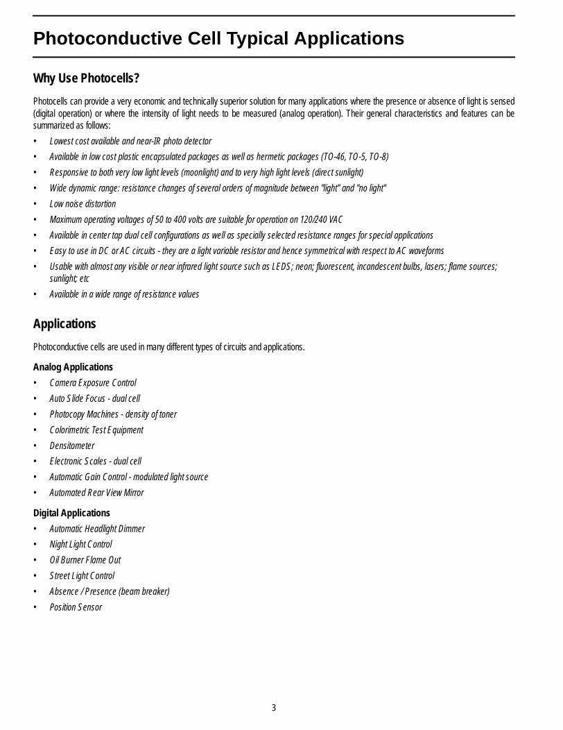
Photocells are thin film devices made by depositing a layer of aphotoconductive material on a ceramic substrate. Metal contacts areevaporated over the surface of the photoconductor and externalelectrical connection is made to these contacts. These thin films ofphotoconductive material have a high sheet resistance. Therefore, thespace between the two contacts is made narrow and interdigitated forlow cell resistance at moderate light levels. This construction is shownin Figure 3.
Figure 3Typical Construction of a Plastic Coated Photocell
2
Photoconductive Cell Typical Applications
Why Use Photocells?
Photocells can provide a very economic and technically superior solution for many applications where the presence or absence of light is sensed(digital operation) or where the intensity of light needs to be measured (analog operation). Their general characteristics and features can besummarized as follows:
• Lowest cost available and near-IR photo detector
• Available in low cost plastic encapsulated packages as well as hermetic packages (TO-46, TO-5, TO-8)
• Responsive to both very low light levels (moonlight) and to very high light levels (direct sunlight)
• Wide dynamic range: resistance changes of several orders of magnitude between "light" and "no light"
• Low noise distortion
• Maximum operating voltages of 50 to 400 volts are suitable for operation on 120/240 VAC
• Available in center tap dual cell configurations as well as specially selected resistance ranges for special applications
• Easy to use in DC or AC circuits - they are a light variable resistor and hence symmetrical with respect to AC waveforms
• Usable with almost any visible or near infrared light source such as LEDS; neon; fluorescent, incandescent bulbs, lasers; flame sources; sunlight; etc
• Available in a wide range of resistance values
Applications
Photoconductive cells are used in many different types of circuits and applications.
Analog Applications
• Camera Exposure Control
• Auto Slide Focus - dual cell
• Photocopy Machines - density of toner
• Colorimetric Test Equipment
• Densitometer
• Electronic Scales - dual cell
• Automatic Gain Control - modulated light source
• Automated Rear View Mirror
Digital Applications
• Automatic Headlight Dimmer
• Night Light Control
• Oil Burner Flame Out
• Street Light Control
• Absence / Presence (beam breaker)
• Position Sensor
3
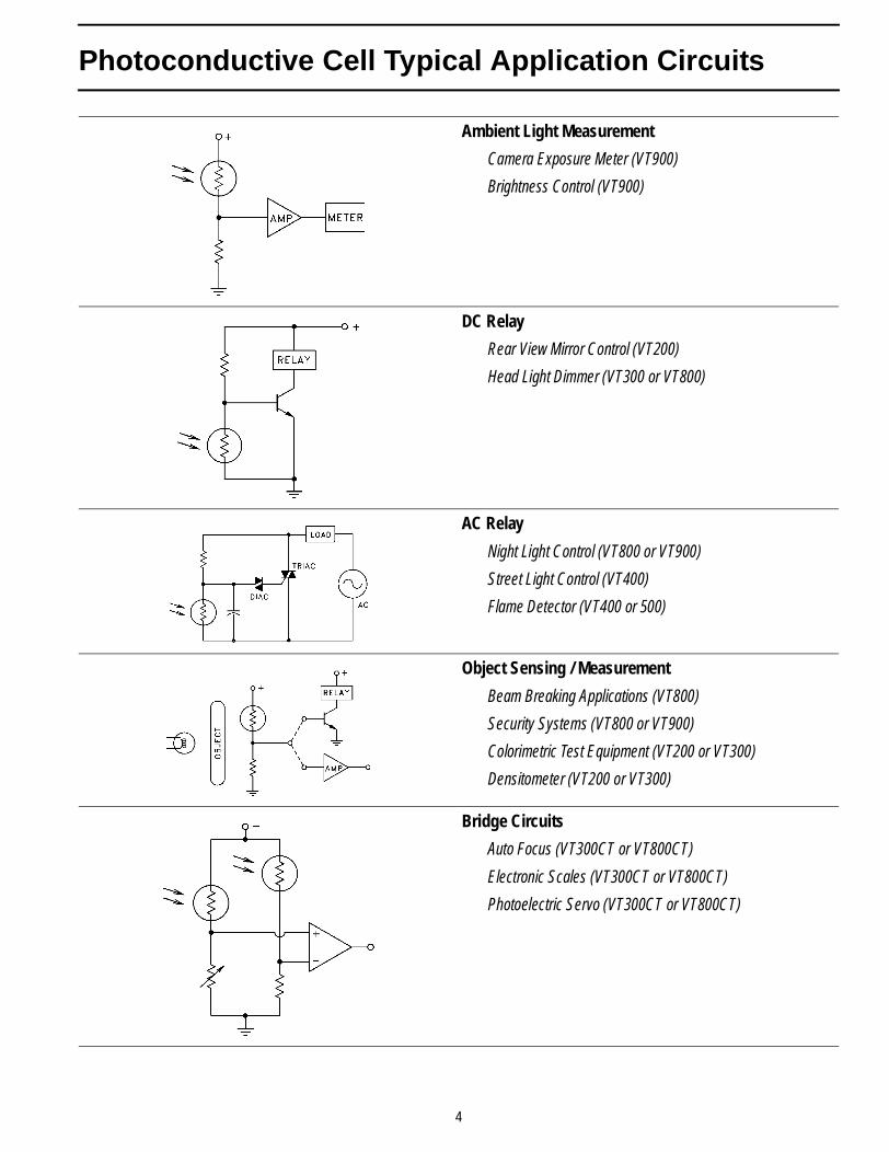
Photoconductive Cell Typical Application Circuits
Ambient Light Measurement
Camera Exposure Meter (VT900)
Brightness Control (VT900)
DC Relay
Rear View Mirror Control (VT200)
Head Light Dimmer (VT300 or VT800)
AC Relay
Night Light Control (VT800 or VT900)
Street Light Control (VT400)
Flame Detector (VT400 or 500)
Object Sensing / Measurement
Beam Breaking Applications (VT800)
Security Systems (VT800 or VT900)
Colorimetric Test Equipment (VT200 or VT300)
Densitometer (VT200 or VT300)
Bridge Circuits
Auto Focus (VT300CT or VT800CT)
Electronic Scales (VT300CT or VT800CT)
Photoelectric Servo (VT300CT or VT800CT)
4
Selecting a Photocell
Specifying the best photoconductive cell for your application requiresan understanding of its principles of operation. This section reviewssome fundamentals of photocell technology to help you get the bestblend of parameters for your application.
When selecting a photocell the design engineer must ask two basicquestions:
1. What kind of performance is required from the cell?
2. What kind of environment must the cell work in?
Performance Criteria
Sensitivity
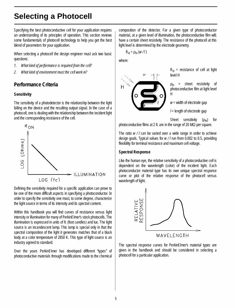
The sensitivity of a photodetector is the relationship between the lightfalling on the device and the resulting output signal. In the case of aphotocell, one is dealing with the relationship between the incident lightand the corresponding resistance of the cell.
Defining the sensitivity required for a specific application can prove tobe one of the more difficult aspects in specifying a photoconductor. Inorder to specify the sensitivity one must, to some degree, characterizethe light source in terms of its intensity and its spectral content.
Within this handbook you will find curves of resistance versus lightintensity or illumination for many of PerkinElmer’s stock photocells. Theillumination is expressed in units of fc (foot candles) and lux. The lightsource is an incandescent lamp. This lamp is special only in that thespectral composition of the light it generates matches that of a blackbody at a color temperature of 2850 K. This type of light source is anindustry agreed to standard.
Over the years PerkinElmer has developed different “types” ofphotoconductive materials through modifications made to the chemical
composition of the detector. For a given type of photoconductormaterial, at a given level of illumination, the photoconductive film will;have a certain sheet resistivity. The resistance of the photocell at thislight level is determined by the electrode geometry.
RH = ρH (w / l )
where:
RH = resistance of cell at lightlevel H
ρH = sheet resistivity ofphotoconductive film at light levelH
w = width of electrode gap
l = length of electrode gap
Sheet sensitivity (ρH) forphotoconductive films at 2 fc are in the range of 20 MΩ per square.
The ratio w / l can be varied over a wide range in order to achievedesign goals. Typical values for w / l run from 0.002 to 0.5, providingflexibility for terminal resistance and maximum cell voltage.
Spectral Response
Like the human eye, the relative sensitivity of a photoconductive cell isdependent on the wavelength (color) of the incident light. Eachphotoconductor material type has its own unique spectral responsecurve or plot of the relative response of the photocell versuswavelength of light.
The spectral response curves for PerkinElmer’s material types aregiven in the handbook and should be considered in selecting aphotocell for a particular application.
5
Selecting a Photocell
Slope Characteristics
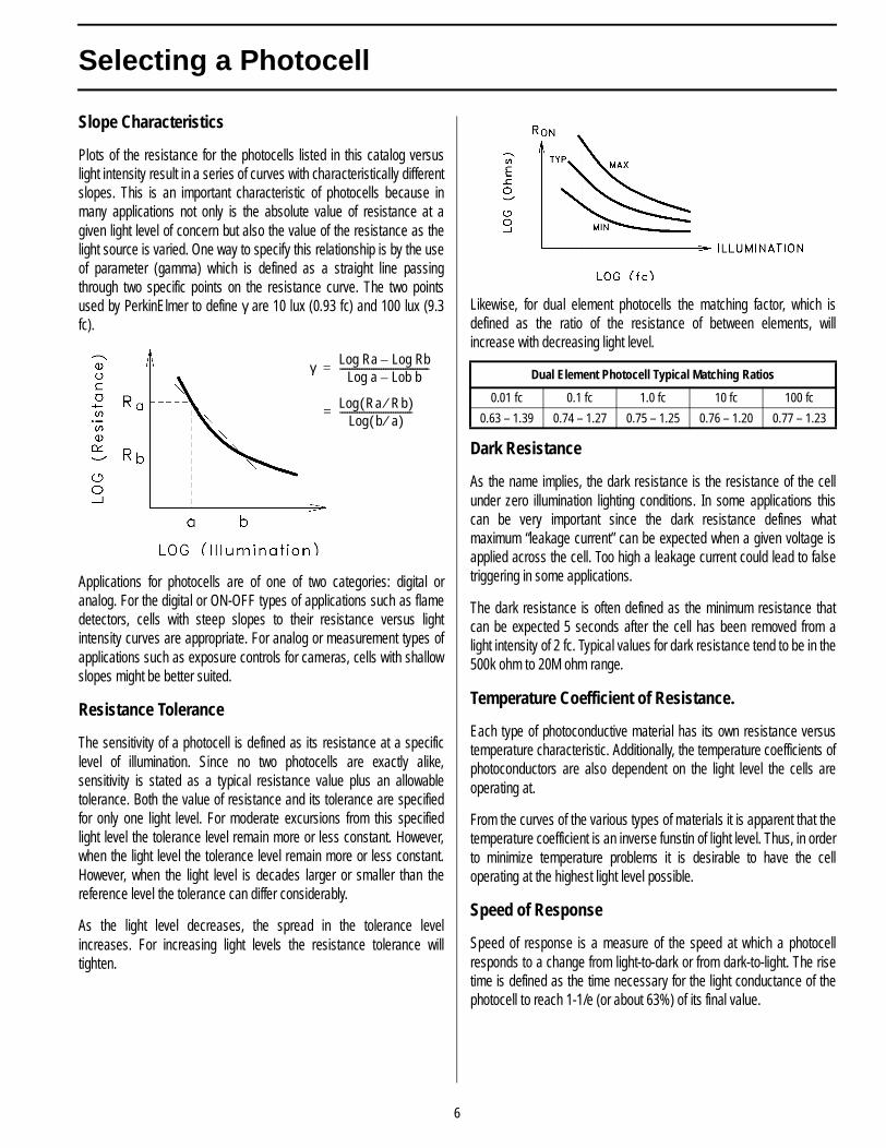
Plots of the resistance for the photocells listed in this catalog versuslight intensity result in a series of curves with characteristically differentslopes. This is an important characteristic of photocells because inmany applications not only is the absolute value of resistance at agiven light level of concern but also the value of the resistance as thelight source is varied. One way to specify this relationship is by the useof parameter (gamma) which is defined as a straight line passingthrough two specific points on the resistance curve. The two pointsused by PerkinElmer to define γ are 10 lux (0.93 fc) and 100 lux (9.3fc).
Applications for photocells are of one of two categories: digital oranalog. For the digital or ON-OFF types of applications such as flamedetectors, cells with steep slopes to their resistance versus lightintensity curves are appropriate. For analog or measurement types ofapplications such as exposure controls for cameras, cells with shallowslopes might be better suited.
Resistance Tolerance
The sensitivity of a photocell is defined as its resistance at a specificlevel of illumination. Since no two photocells are exactly alike,sensitivity is stated as a typical resistance value plus an allowabletolerance. Both the value of resistance and its tolerance are specifiedfor only one light level. For moderate excursions from this specifiedlight level the tolerance level remain more or less constant. However,when the light level the tolerance level remain more or less constant.However, when the light level is decades larger or smaller than thereference level the tolerance can differ considerably.
As the light level decreases, the spread in the tolerance levelincreases. For increasing light levels the resistance tolerance willtighten.
Likewise, for dual element photocells the matching factor, which isdefined as the ratio of the resistance of between elements, willincrease with decreasing light level.
Dark Resistance
As the name implies, the dark resistance is the resistance of the cellunder zero illumination lighting conditions. In some applications thiscan be very important since the dark resistance defines whatmaximum “leakage current” can be expected when a given voltage isapplied across the cell. Too high a leakage current could lead to falsetriggering in some applications.
The dark resistance is often defined as the minimum resistance thatcan be expected 5 seconds after the cell has been removed from alight intensity of 2 fc. Typical values for dark resistance tend to be in the500k ohm to 20M ohm range.
Temperature Coefficient of Resistance.
Each type of photoconductive material has its own resistance versustemperature characteristic. Additionally, the temperature coefficients ofphotoconductors are also dependent on the light level the cells areoperating at.
From the curves of the various types of materials it is apparent that thetemperature coefficient is an inverse funstin of light level. Thus, in orderto minimize temperature problems it is desirable to have the celloperating at the highest light level possible.
Speed of Response
Speed of response is a measure of the speed at which a photocellresponds to a change from light-to-dark or from dark-to-light. The risetime is defined as the time necessary for the light conductance of thephotocell to reach 1-1/e (or about 63%) of its final value.
γ Log Ra Log Rb–Log a Lob b–
-------------------------------------=
Log Ra Rb⁄( )Log b a⁄( )
------------------------------=
Dual Element Photocell Typical Matching Ratios
0.01 fc 0.1 fc 1.0 fc 10 fc 100 fc
0.63 – 1.39 0.74 – 1.27 0.75 – 1.25 0.76 – 1.20 0.77 – 1.23
6
Selecting a Photocell
The decay or fall time is defined as the time necessary for the lightconductance of the photocell to decay to 1/e (or about 73%) of itsilluminated state. At 1 fc of illumination the response times are typicallyin the range of 5 msec to 100 msec.The speed of response depends on a number of factors including lightlevel, light history, and ambient temperature. All material types showfaster speed at higher light levels and slower speed at lower lightlevels. Storage in the dark will cause slower response than if the cellsare kept in the light. The longer the photocells are kept in the dark themore pronounced this effect will be. In addition, photocells tend torespond slower in colder temperatures.
Light History
All photoconductive cells exhibit a phenomenon known as hysteresis,light memory, or light history effect. Simply stated, a photocell tends toremember its most recent storage condition (light or dark) and itsinstantaneous conductance is a function of its previous condition. Themagnitude of the light history effect depends upon the new light level,and upon the time spent at each of these light levels. this effect isreversible.
To understand the light history effect, it is often convenient to make ananalogy between the response of a photocell and that of a human eye.Like the cell, the human eye’s sensitivity to light depends on what levelof light it was recently exposed to. Most people have had theexperience of coming in from the outdoors on a bright summer’s dayand being temporarily unable to see under normal room levels ofillumination. your eyes will adjust but a certain amount of time mustelapse first. how quickly one’s eyes adjust depends on how bright itwas outside and how long you remained outdoors.
The following guide shows the general relationship between lighthistory and light resistance at various light levels. The values shownwere determined by dividing the resistance of a given cell, followinginfinite light history (RLH), by the resistance of the same cell following“infinite” dark history (RDH). For practical purposes, 24 hours in thedark will achieve RDH or 24 hours at approximately 30 fc will achieveRLH.
Typical Variation of Resistance with Light History Expressed as a Ratio RLH / RDH at Various Test Illumination Levels.
This guide illustrates the fact that a photocell which has been stored fora long time in the light will have a considerably higher light resistancethan if it was stored for a long time in the dark. Also, if a cell is storedfor a long period of time at a light level higher than the test level, it willhave a higher light resistance than if it was stored at a light level closerto the test light level.
This effect can be minimized significantly by keeping the photocellexposed to some constant low level of illumination (as opposed tohaving it sit in the dark). This is the reason resistance specificationsare characterized after 16 hours light adept.
Environmental/Circuitry Considerations
Packaging
In order to be protected from potentially hostile environmentsphotocells are encapsulated in either glass/metal (hermetic) packageor are covered with a clear plastic coating. While the hermeticpackages provide the greatest degree of protection, a plastic coatingrepresents a lower cost approach.
The disadvantage of plastic coatings is that they are not an absolutebarrier to eventual penetration by moisture. This can have an adverseeffect on cell life. However, plastic coated photocells have been usedsuccessfully for many years in such hostile environments as street lightcontrols.
Temperature Range
The chemistry of the photoconductive materials dictates an operatingand storage temperature range of –40°C to 75°C. It should be notedthat operation of the cell above 75°C does not usually lead tocatastrophic failure but the photoconductive surface may be damagedleading to irreversible changes in sensitivity.
The amount of resistance change is a function of time as well astemperature. While changes of several hundred percent will occur in amatter of a few minutes at 150°C, it will take years at 50°C to producethat much change.
Power Dissipation
During operation, a cell must remain within its maximum internaltemperature rating of 75°C. Any applied power will raise the cell’stemperature above ambient and must be considered.
Illumination
RLH / RDH Ratio
0.01 fc 0.1 fc 1.0 fc 10 fc 100 fc
1.55 1.35 1.20 1.10 1.10
7
Selecting a Photocell
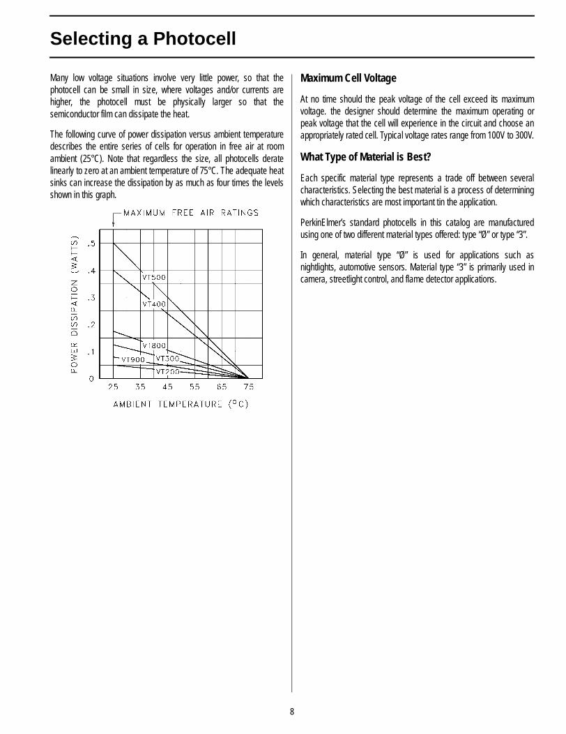
Many low voltage situations involve very little power, so that thephotocell can be small in size, where voltages and/or currents arehigher, the photocell must be physically larger so that thesemiconductor film can dissipate the heat.
The following curve of power dissipation versus ambient temperaturedescribes the entire series of cells for operation in free air at roomambient (25°C). Note that regardless the size, all photocells deratelinearly to zero at an ambient temperature of 75°C. The adequate heatsinks can increase the dissipation by as much as four times the levelsshown in this graph.
Maximum Cell Voltage
At no time should the peak voltage of the cell exceed its maximumvoltage. the designer should determine the maximum operating orpeak voltage that the cell will experience in the circuit and choose anappropriately rated cell. Typical voltage rates range from 100V to 300V.
What Type of Material is Best?
Each specific material type represents a trade off between severalcharacteristics. Selecting the best material is a process of determiningwhich characteristics are most important tin the application.
PerkinElmer’s standard photocells in this catalog are manufacturedusing one of two different material types offered: type “Ø” or type “3”.
In general, material type “Ø” is used for applications such asnightlights, automotive sensors. Material type “3” is primarily used incamera, streetlight control, and flame detector applications.
8
Photoconductive Cell Typical Characteristic Curves
@ 25°C Type Ø Material
Type Ø Material
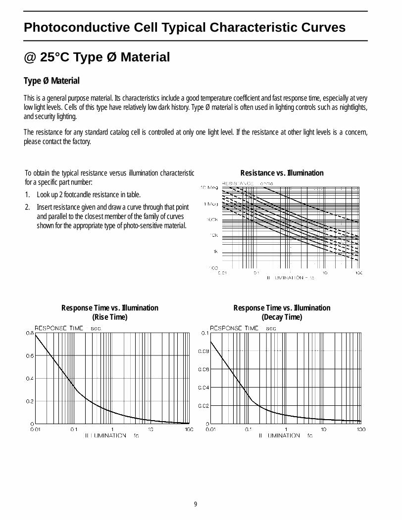
This is a general purpose material. Its characteristics include a good temperature coefficient and fast response time, especially at verylow light levels. Cells of this type have relatively low dark history. Type Ø material is often used in lighting controls such as nightlights,and security lighting.
The resistance for any standard catalog cell is controlled at only one light level. If the resistance at other light levels is a concern,please contact the factory.
To obtain the typical resistance versus illumination characteristicfor a specific part number:
1. Look up 2 footcandle resistance in table.
2. Insert resistance given and draw a curve through that point and parallel to the closest member of the family of curves shown for the appropriate type of photo-sensitive material.
Resistance vs. Illumination
Response Time vs. Illumination(Rise Time)
Response Time vs. Illumination(Decay Time)
9
Photoconductive Cell Typical Characteristic Curves
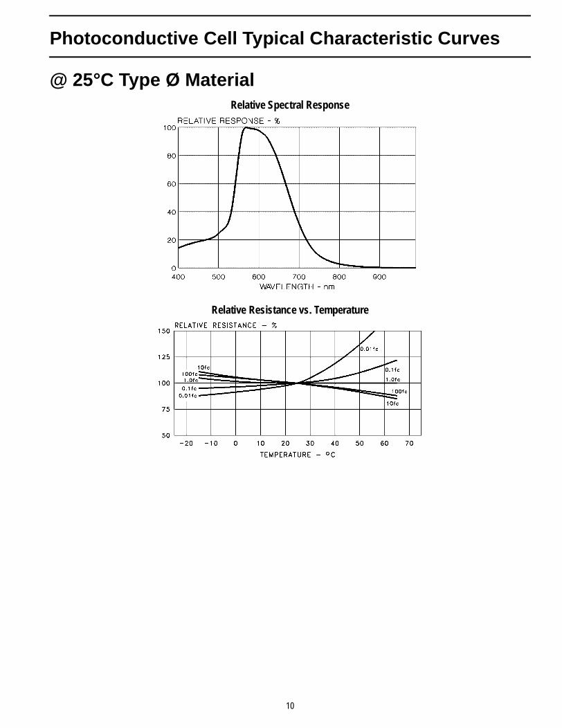
@ 25°C Type Ø MaterialRelative Spectral Response
Relative Resistance vs. Temperature
10
Photoconductive Cell Typical Characteristic Curves
@ 25°C Type 3 Material
Type 3 Material
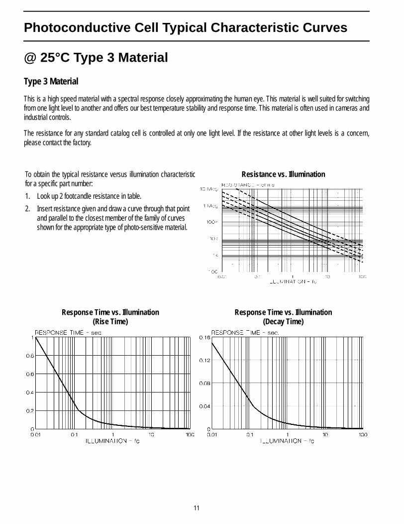
This is a high speed material with a spectral response closely approximating the human eye. This material is well suited for switchingfrom one light level to another and offers our best temperature stability and response time. This material is often used in cameras andindustrial controls.
The resistance for any standard catalog cell is controlled at only one light level. If the resistance at other light levels is a concern,please contact the factory.
To obtain the typical resistance versus illumination characteristicfor a specific part number:
1. Look up 2 footcandle resistance in table.
2. Insert resistance given and draw a curve through that point and parallel to the closest member of the family of curves shown for the appropriate type of photo-sensitive material.
Resistance vs. Illumination
Response Time vs. Illumination(Rise Time)
Response Time vs. Illumination(Decay Time)
11
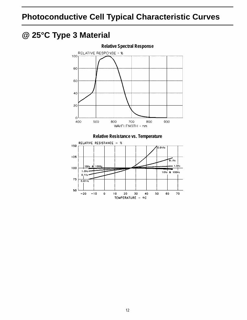
Photoconductive Cell Typical Characteristic Curves
@ 25°C Type 3 MaterialRelative Spectral Response
Relative Resistance vs. Temperature
12
Photoconductive Cell Testing and General Notes
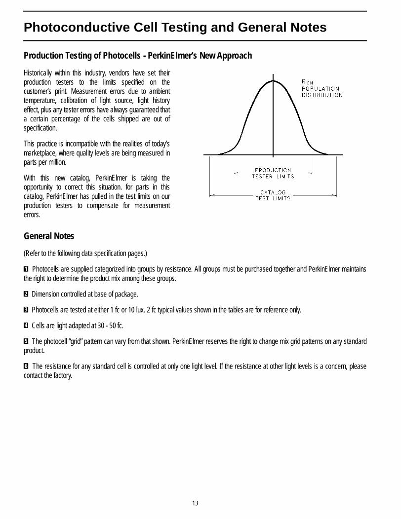
Production Testing of Photocells - PerkinElmer’s New Approach
Historically within this industry, vendors have set theirproduction testers to the limits specified on thecustomer’s print. Measurement errors due to ambienttemperature, calibration of light source, light historyeffect, plus any tester errors have always guaranteed thata certain percentage of the cells shipped are out ofspecification.
This practice is incompatible with the realities of today’smarketplace, where quality levels are being measured inparts per million.
With this new catalog, PerkinElmer is taking theopportunity to correct this situation. for parts in thiscatalog, PerkinElmer has pulled in the test limits on ourproduction testers to compensate for measurementerrors.
General Notes
(Refer to the following data specification pages.)
Photocells are supplied categorized into groups by resistance. All groups must be purchased together and PerkinElmer maintainsthe right to determine the product mix among these groups.
Dimension controlled at base of package.
Photocells are tested at either 1 fc or 10 lux. 2 fc typical values shown in the tables are for reference only.
Cells are light adapted at 30 - 50 fc.
The photocell “grid” pattern can vary from that shown. PerkinElmer reserves the right to change mix grid patterns on any standardproduct.
The resistance for any standard cell is controlled at only one light level. If the resistance at other light levels is a concern, pleasecontact the factory.
1
2
3
4
5
6
13


![[Nonuniform primary photocurrent spreading in quantum well infrared photoconductors]](https://img.pdfslide.net/doc/110x75/56813ff8550346895dab28e9/nonuniform-primary-photocurrent-spreading-in-quantum-well-infrared-photoconductors.jpg)