Embed Size (px)
Citation preview
PHYS-2020: General Physics IICourse Lecture Notes
Section IV
Dr. Donald G. Luttermoser
East Tennessee State University
Edition 4.0
Abstract
These class notes are designed for use of the instructor and students of the course PHYS-2020:General Physics II taught by Dr. Donald Luttermoser at East Tennessee State University. Thesenotes make reference to the College Physics, 10th Hybrid Edition (2015) textbook by Serway andVuille.
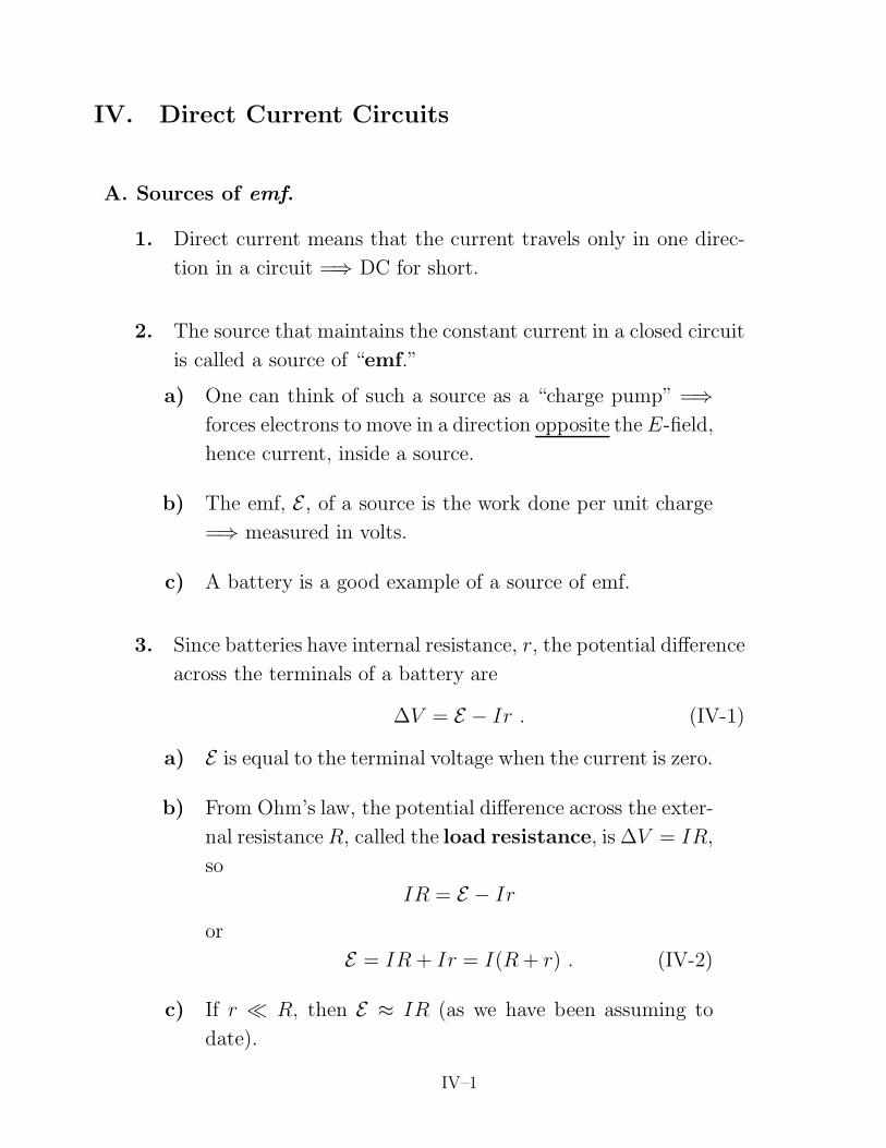
IV. Direct Current Circuits
A. Sources of emf.
1. Direct current means that the current travels only in one direc-
tion in a circuit =⇒ DC for short.
2. The source that maintains the constant current in a closed circuit
is called a source of “emf.”
a) One can think of such a source as a “charge pump” =⇒
forces electrons to move in a direction opposite the E-field,
hence current, inside a source.
b) The emf, E , of a source is the work done per unit charge
=⇒ measured in volts.
c) A battery is a good example of a source of emf.
3. Since batteries have internal resistance, r, the potential difference
across the terminals of a battery are
∆V = E − Ir . (IV-1)
a) E is equal to the terminal voltage when the current is zero.
b) From Ohm’s law, the potential difference across the exter-
nal resistance R, called the load resistance, is ∆V = IR,
so
IR = E − Ir
or
E = IR + Ir = I(R + r) . (IV-2)
c) If r R, then E ≈ IR (as we have been assuming to
date).
IV–1
IV–2 PHYS-2020: General Physics II
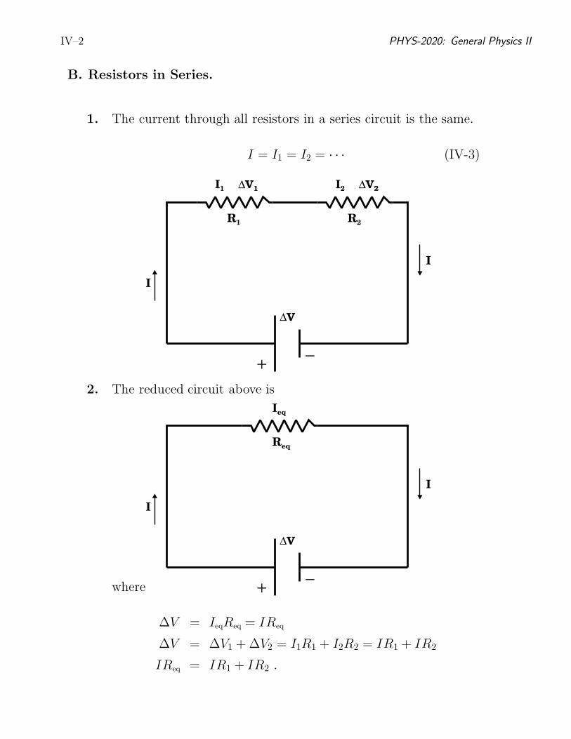
B. Resistors in Series.
1. The current through all resistors in a series circuit is the same.
I = I1 = I2 = · · · (IV-3)
R1
I1 ∆V1
R2
I2 ∆V2
−+
∆V
I
I
2. The reduced circuit above is
Req
Ieq
−+
∆V
I
I
where
∆V = IeqReq = IReq
∆V = ∆V1 + ∆V2 = I1R1 + I2R2 = IR1 + IR2
IReq = IR1 + IR2 .
Donald G. Luttermoser, ETSU IV–3
3. As such, we can express the equivalent resistance as
Req = R1 + R2 (IV-4)
for two series resistors or more generally (e.g., for more than 2
resistors in series) as
Req =N∑
i=1
Ri ,
series circuits(IV-5)
where N is the total number of resistors.
4. Once the equivalent resistance is found, one can then calculate I
from ∆V using Ohm’s law.
C. Resistors in Parallel.
1. When resistors are connected in parallel, the potential difference
across them are the same:
∆V1 = ∆V
R1
I1
∆V2 = ∆V
R2
I2
−+
∆V
II
⇓
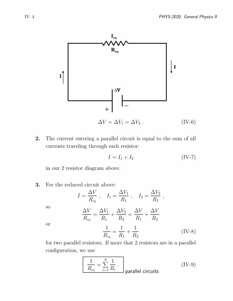
IV–4 PHYS-2020: General Physics II
Req
Ieq
−+
∆V
I
I
∆V = ∆V1 = ∆V2 . (IV-6)
2. The current entering a parallel circuit is equal to the sum of all
currents traveling through each resistor:
I = I1 + I2 (IV-7)
in our 2 resistor diagram above.
3. For the reduced circuit above:
I =∆V
Req
, I1 =∆V1
R1
, I2 =∆V2
R2
,
so∆V
Req
=∆V1
R1
+∆V2
R2
=∆V
R1
+∆V
R2
or1
Req
=1
R1
+1
R2
(IV-8)
for two parallel resistors. If more that 2 resistors are in a parallel
configuration, we use
1
Req
=N∑
i=1
1
Ri.
parallel circuits(IV-9)
Donald G. Luttermoser, ETSU IV–5
4. Once the equivalent resistance is found, this info can be used to
deduce either the voltages or the individual currents across the
resistors.
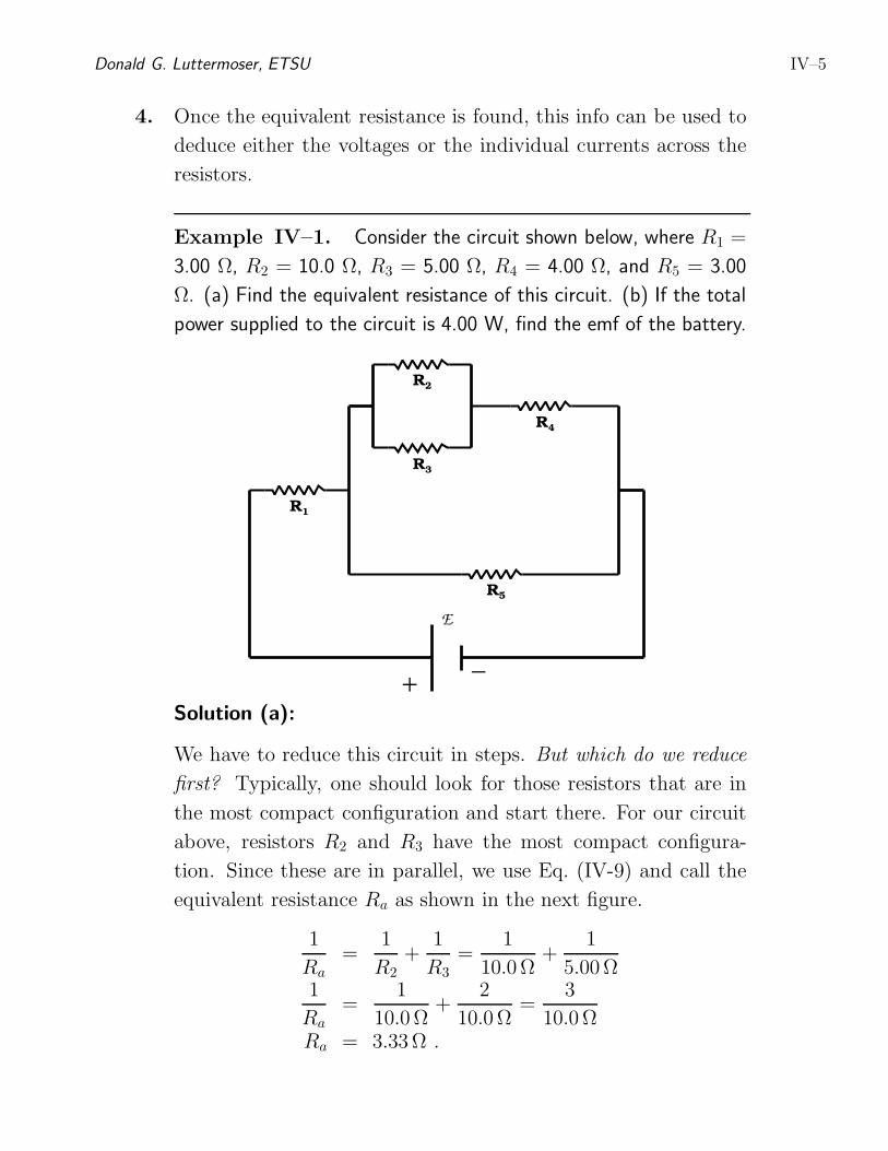
Example IV–1. Consider the circuit shown below, where R1 =
3.00 Ω, R2 = 10.0 Ω, R3 = 5.00 Ω, R4 = 4.00 Ω, and R5 = 3.00
Ω. (a) Find the equivalent resistance of this circuit. (b) If the total
power supplied to the circuit is 4.00 W, find the emf of the battery.
−+
E
R1
R2
R3
R4
R5
Solution (a):
We have to reduce this circuit in steps. But which do we reduce
first? Typically, one should look for those resistors that are in
the most compact configuration and start there. For our circuit
above, resistors R2 and R3 have the most compact configura-
tion. Since these are in parallel, we use Eq. (IV-9) and call the
equivalent resistance Ra as shown in the next figure.
1
Ra=
1
R2
+1
R3
=1
10.0Ω+
1
5.00Ω1
Ra=
1
10.0Ω+
2
10.0Ω=
3
10.0ΩRa = 3.33Ω .
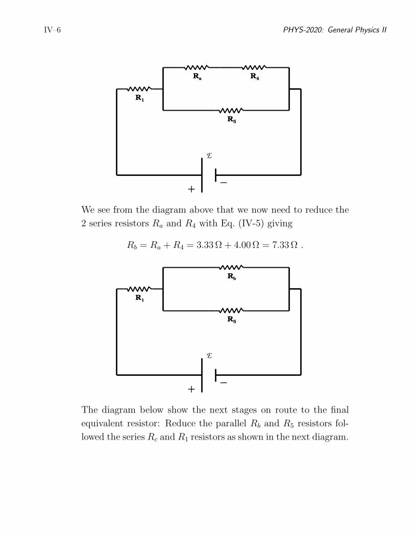
IV–6 PHYS-2020: General Physics II
−+
E
R1
Ra R4
R5
We see from the diagram above that we now need to reduce the
2 series resistors Ra and R4 with Eq. (IV-5) giving
Rb = Ra + R4 = 3.33Ω + 4.00Ω = 7.33Ω .
−+
E
R1
Rb
R5
The diagram below show the next stages on route to the final
equivalent resistor: Reduce the parallel Rb and R5 resistors fol-
lowed the series Rc and R1 resistors as shown in the next diagram.
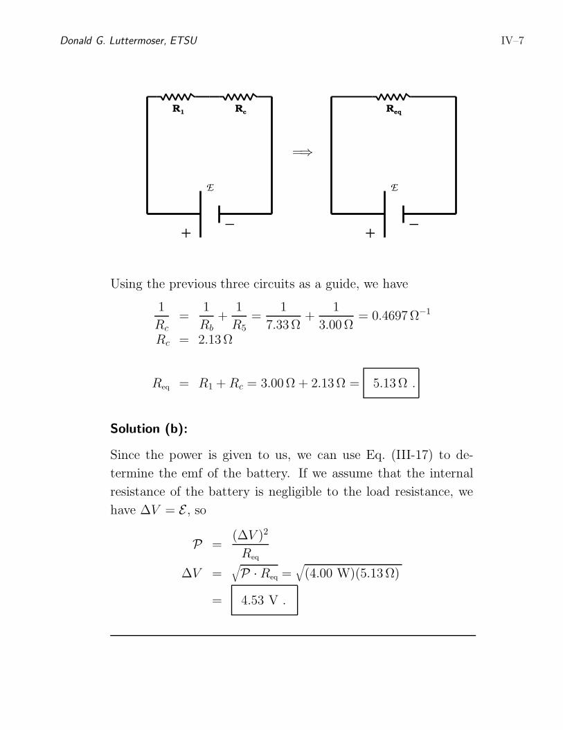
Donald G. Luttermoser, ETSU IV–7
−+
E
R1 Rc
−+
E
Req
=⇒
Using the previous three circuits as a guide, we have
1
Rc=
1
Rb+
1
R5
=1
7.33Ω+
1
3.00Ω= 0.4697Ω−1
Rc = 2.13Ω
Req = R1 + Rc = 3.00Ω + 2.13Ω = 5.13Ω .
Solution (b):
Since the power is given to us, we can use Eq. (III-17) to de-
termine the emf of the battery. If we assume that the internal
resistance of the battery is negligible to the load resistance, we
have ∆V = E , so
P =(∆V )2
Req
∆V =√
P · Req =√
(4.00 W)(5.13Ω)
= 4.53 V .
IV–8 PHYS-2020: General Physics II
D. Kirchhoff’s Rules and Complex DC Circuits.
1. For complex DC circuits, it is not always possible to reduce all of
the individual elements of the circuit into a single reduced circuit.
2. In such cases, one should use Kirchhoff’s rules to figure out
the currents and potential differences across each element in the
circuit.
a) The sum of the current entering any junction must equal
the sum of the currents leaving the junction =⇒ the junc-
tion rule (see Figure 18.12 in your textbook).
b) The sum of the potential differences across all of the ele-
ments around any closed circuit loop must be zero =⇒ the
loop rule =⇒ this is nothing more than the conservation
of energy (see Figure 18.14 in your textbook).
i) Going across a battery from + to − is equivalent to
saying you are going in the −∆V or −E direction.
ii) Going across a battery from − to + is equivalent
to going in the +∆V or +E direction.
iii) Going in the opposite direction to current is equiv-
alent to saying you are going in the +IR direction.
iv) Going in the same direction as current is equiva-
lent to saying you are going in the −IR direction.
v) Current flows from +V to −V in a circuit.
Donald G. Luttermoser, ETSU IV–9
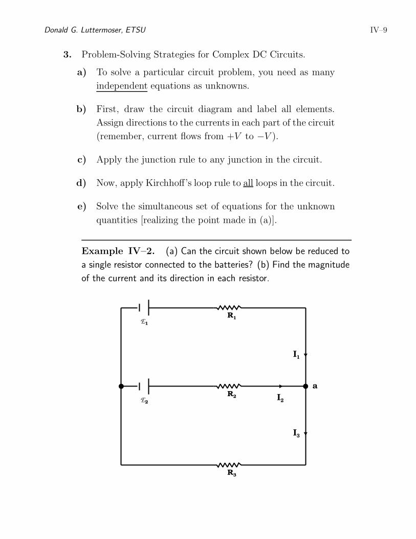
3. Problem-Solving Strategies for Complex DC Circuits.
a) To solve a particular circuit problem, you need as many
independent equations as unknowns.
b) First, draw the circuit diagram and label all elements.
Assign directions to the currents in each part of the circuit
(remember, current flows from +V to −V ).
c) Apply the junction rule to any junction in the circuit.
d) Now, apply Kirchhoff’s loop rule to all loops in the circuit.
e) Solve the simultaneous set of equations for the unknown
quantities [realizing the point made in (a)].
Example IV–2. (a) Can the circuit shown below be reduced to
a single resistor connected to the batteries? (b) Find the magnitude
of the current and its direction in each resistor.
E1
R1
E2
R2
R3
I2
I1
I3
a
IV–10 PHYS-2020: General Physics II
Solution (a):
No. This multi-loop circuit does not have any resistors in series
(i.e., connected so all the current in one must pass through the
other) nor in parallel (connected so the voltage drops across one
is always the same as that across the other). Thus, this circuit
cannot be simplified any further, and Kirchoff’s rules must be
used to analyze it.
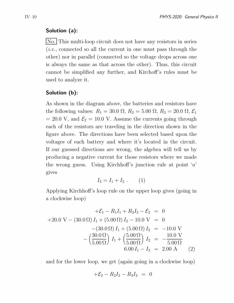
Solution (b):
As shown in the diagram above, the batteries and resistors have
the following values: R1 = 30.0 Ω, R2 = 5.00 Ω, R3 = 20.0 Ω, E1
= 20.0 V, and E2 = 10.0 V. Assume the currents going through
each of the resistors are traveling in the direction shown in the
figure above. The directions have been selected based upon the
voltages of each battery and where it’s located in the circuit.
If our guessed directions are wrong, the algebra will tell us by
producing a negative current for those resistors where we made
the wrong guess. Using Kirchhoff’s junction rule at point ‘a’
gives
I3 = I1 + I2 . (1)
Applying Kirchhoff’s loop rule on the upper loop gives (going in
a clockwise loop)
+E1 − R1I1 + R2I2 − E2 = 0
+20.0 V − (30.0Ω) I1 + (5.00Ω) I2 − 10.0 V = 0
−(30.0Ω) I1 + (5.00Ω) I2 = −10.0 V
−
(
30.0Ω
5.00Ω
)
I1 +
(
5.00Ω
5.00Ω
)
I2 = −10.0 V
5.00Ω6.00 I1 − I2 = 2.00 A (2)
and for the lower loop, we get (again going in a clockwise loop)
+E2 − R2I2 − R3I3 = 0
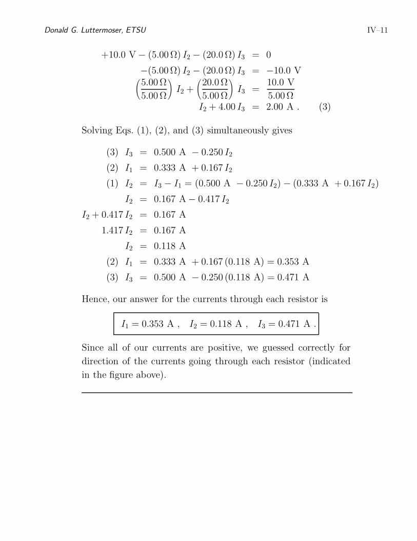
Donald G. Luttermoser, ETSU IV–11
+10.0 V − (5.00Ω) I2 − (20.0Ω) I3 = 0
−(5.00Ω) I2 − (20.0Ω) I3 = −10.0 V(
5.00Ω
5.00Ω
)
I2 +
(
20.0Ω
5.00Ω
)
I3 =10.0 V
5.00ΩI2 + 4.00 I3 = 2.00 A . (3)
Solving Eqs. (1), (2), and (3) simultaneously gives
(3) I3 = 0.500 A − 0.250 I2
(2) I1 = 0.333 A + 0.167 I2
(1) I2 = I3 − I1 = (0.500 A − 0.250 I2) − (0.333 A + 0.167 I2)
I2 = 0.167 A − 0.417 I2
I2 + 0.417 I2 = 0.167 A
1.417 I2 = 0.167 A
I2 = 0.118 A
(2) I1 = 0.333 A + 0.167 (0.118 A) = 0.353 A
(3) I3 = 0.500 A − 0.250 (0.118 A) = 0.471 A
Hence, our answer for the currents through each resistor is
I1 = 0.353 A , I2 = 0.118 A , I3 = 0.471 A .
Since all of our currents are positive, we guessed correctly for
direction of the currents going through each resistor (indicated
in the figure above).
IV–12 PHYS-2020: General Physics II
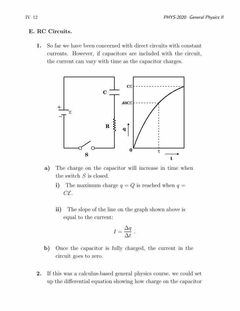
E. RC Circuits.
1. So far we have been concerned with direct circuits with constant
currents. However, if capacitors are included with the circuit,
the current can vary with time as the capacitor charges.
−
+E
C
R
S
q
t
0
EC
E.63C
τ
a) The charge on the capacitor will increase in time when
the switch S is closed.
i) The maximum charge q = Q is reached when q =
CE .
ii) The slope of the line on the graph shown above is
equal to the current:
I =∆q
∆t.
b) Once the capacitor is fully charged, the current in the
circuit goes to zero.
2. If this was a calculus-based general physics course, we could set
up the differential equation showing how charge on the capacitor
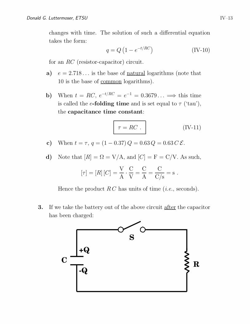
Donald G. Luttermoser, ETSU IV–13
changes with time. The solution of such a differential equation
takes the form:
q = Q(
1 − e−t/RC)
(IV-10)
for an RC (resistor-capacitor) circuit.
a) e = 2.718 . . . is the base of natural logarithms (note that
10 is the base of common logarithms).
b) When t = RC, e−t/RC = e−1 = 0.3679 . . . =⇒ this time
is called the e-folding time and is set equal to τ (‘tau’),
the capacitance time constant:
τ = RC . (IV-11)
c) When t = τ , q = (1 − 0.37) Q = 0.63Q = 0.63C E .
d) Note that [R] = Ω = V/A, and [C] = F = C/V. As such,
[τ ] = [R] [C] =V
A·C
V=
C
A=
C
C/s= s .
Hence the product R C has units of time (i.e., seconds).
3. If we take the battery out of the above circuit after the capacitor
has been charged:
C
-Q
+Q
S
R
IV–14 PHYS-2020: General Physics II
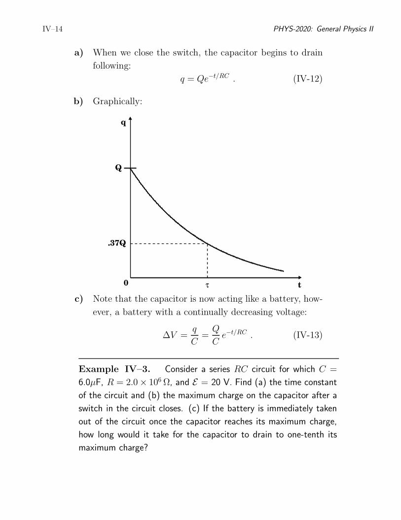
a) When we close the switch, the capacitor begins to drain
following:
q = Qe−t/RC . (IV-12)
b) Graphically:
t0
q
Q
.37Q
τ
c) Note that the capacitor is now acting like a battery, how-
ever, a battery with a continually decreasing voltage:
∆V =q
C=
Q
Ce−t/RC . (IV-13)
Example IV–3. Consider a series RC circuit for which C =
6.0µF, R = 2.0 × 10⁶ Ω, and E = 20 V. Find (a) the time constant
of the circuit and (b) the maximum charge on the capacitor after a
switch in the circuit closes. (c) If the battery is immediately taken
out of the circuit once the capacitor reaches its maximum charge,
how long would it take for the capacitor to drain to one-tenth its
maximum charge?
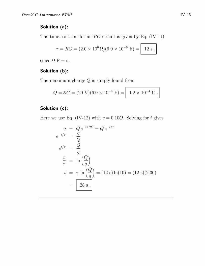
Donald G. Luttermoser, ETSU IV–15
Solution (a):
The time constant for an RC circuit is given by Eq. (IV-11):
τ = RC = (2.0 × 10⁶ Ω)(6.0 × 10⁻⁶ F) = 12 s ,
since Ω·F = s.
Solution (b):
The maximum charge Q is simply found from
Q = EC = (20 V)(6.0 × 10⁻⁶ F) = 1.2 × 10⁻⁴ C .
Solution (c):
Here we use Eq. (IV-12) with q = 0.10Q. Solving for t gives
q = Qe−t/RC = Qe−t/τ
e−t/τ =q
Q
et/τ =Q
q
t
τ= ln
(
Q
q
)
t = τ ln
(
Q
q
)
= (12 s) ln(10) = (12 s)(2.30)
= 28 s .