Embed Size (px)
Citation preview
Copyright © 2008-2013 Pico Technology Limited. All rights reserved.
PicoScope 2203
User's Guide
ps2203.en r4
PC Oscilloscopes


IPicoScope 2203 User's Guide
Copyright © 2008-2013 Pico Technology Limited. All rights reserved. ps2203.en r4
Contents....................................................................................................................................11 Welcome
....................................................................................................................................22 Introduction
........................................................................................................................................21 Using this guide
........................................................................................................................................22 Safety symbols
........................................................................................................................................33 Safety warning
........................................................................................................................................44 FCC notice
........................................................................................................................................45 CE notice
........................................................................................................................................56 Software licence conditions
........................................................................................................................................67 Trademarks
........................................................................................................................................68 Warranty
........................................................................................................................................69 Company details
....................................................................................................................................73 Product information
........................................................................................................................................71 What do I get?
........................................................................................................................................72 System requirements
........................................................................................................................................83 Installation instructions
........................................................................................................................................94 Connections
......................................................................................................................................................................91 Connector diagrams ......................................................................................................................................................................102 Signal inputs ......................................................................................................................................................................103 Signal Out connector ......................................................................................................................................................................104 USB port
........................................................................................................................................115 Specifications
....................................................................................................................................124 Glossary
....................................................................................................................................145 Appendix A: Declaration of Conformity
....................................................................................................................................15Index

PicoScope 2203 User's Guide 1
Copyright © 2008-2013 Pico Technology Limited. All rights reserved. ps2203.en r4
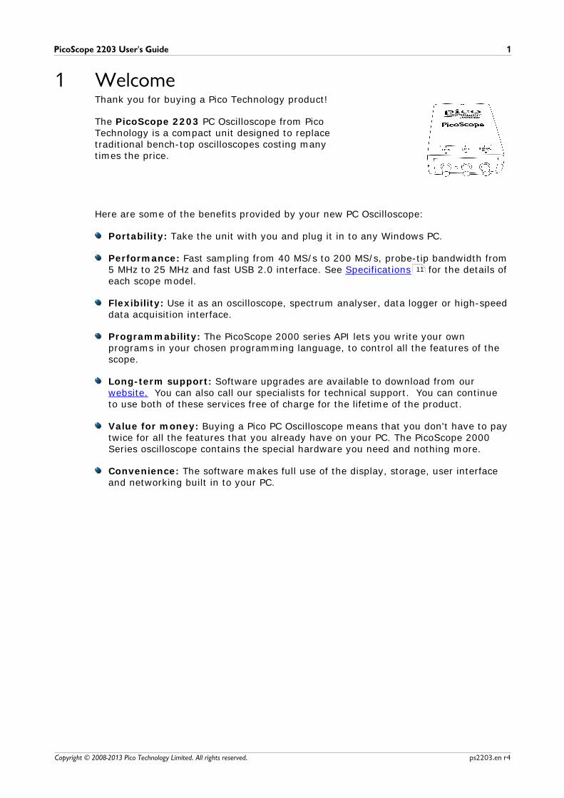
1 WelcomeThank you for buying a Pico Technology product!
The PicoScope 2203 PC Oscilloscope from PicoTechnology is a compact unit designed to replacetraditional bench-top oscilloscopes costing manytimes the price.
Here are some of the benefits provided by your new PC Oscilloscope:
Portability: Take the unit with you and plug it in to any Windows PC.
Performance: Fast sampling from 40 MS/s to 200 MS/s, probe-tip bandwidth from5 MHz to 25 MHz and fast USB 2.0 interface. See Specifications for the details ofeach scope model.
Flexibility: Use it as an oscilloscope, spectrum analyser, data logger or high-speeddata acquisition interface.
Programmability: The PicoScope 2000 series API lets you write your ownprograms in your chosen programming language, to control all the features of thescope.
Long-term support: Software upgrades are available to download from ourwebsite. You can also call our specialists for technical support. You can continueto use both of these services free of charge for the lifetime of the product.
Value for money: Buying a Pico PC Oscilloscope means that you don't have to paytwice for all the features that you already have on your PC. The PicoScope 2000Series oscilloscope contains the special hardware you need and nothing more.
Convenience: The software makes full use of the display, storage, user interfaceand networking built in to your PC.
11
Introduction2
Copyright © 2008-2013 Pico Technology Limited. All rights reserved.ps2203.en r4
2 Introduction2.1 Using this guide
In this guide you will see symbols like this: This is the cross-reference symbol,and it indicates the number of a page on which you can find more information about atopic.
The abbreviation MS/s is used in this guide to mean megasamples per second.
2.2 Safety symbolsThe following symbols appear on the top of the PicoScope 2203 PC Oscilloscope.
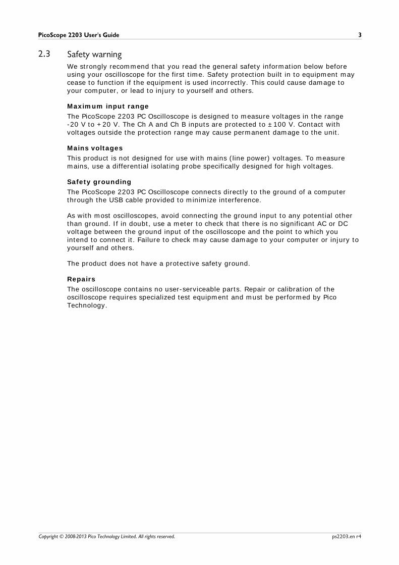
Symbol 1: Warning triangle
This symbol indicates that a safety hazard exists on the indicatedconnections if correct precautions are not taken. Read all safetydocumentation associated with the product before using it.
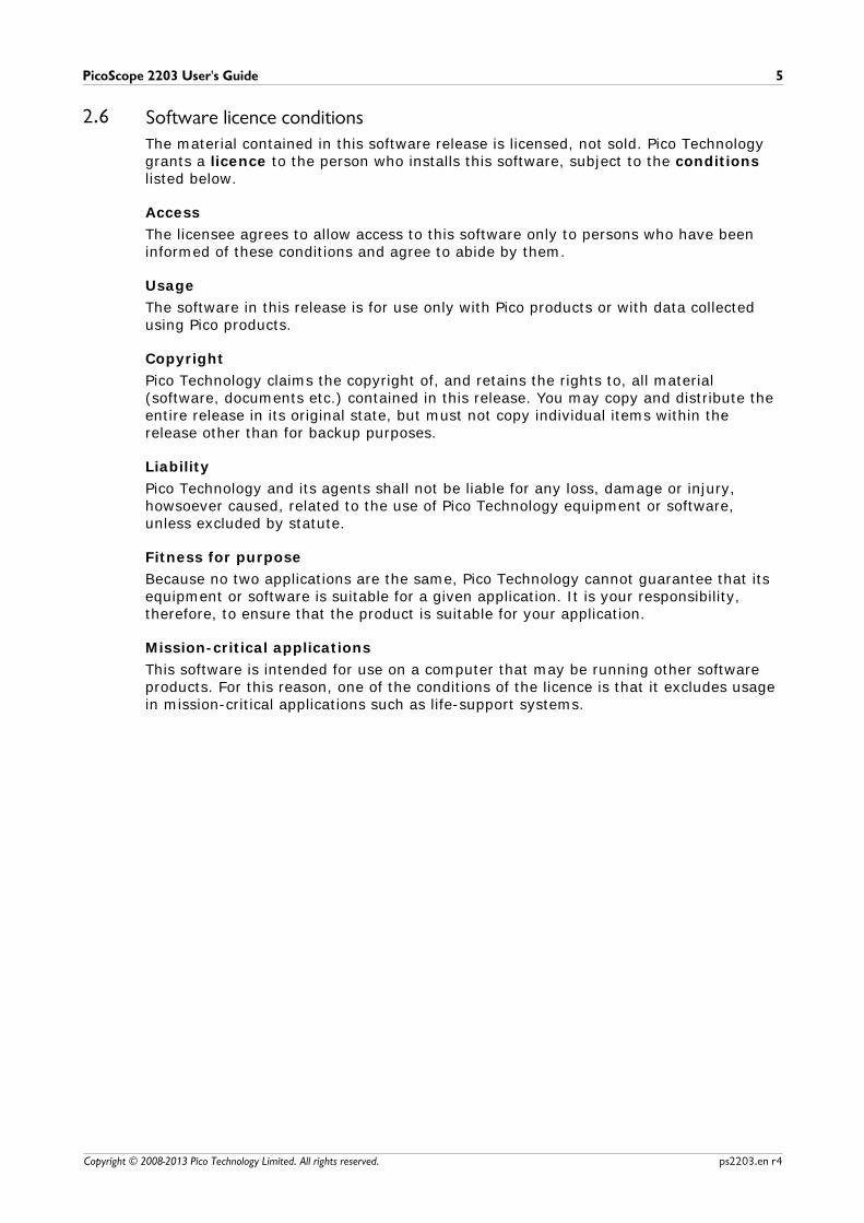
Symbol 2: Equipotential
This symbol indicates that the outer shells of the indicated BNCconnectors are all at the same potential (shorted together). Youmust therefore take necessary precautions to avoid applying apotential across the return connections of the indicated BNCterminals. Such a potential could cause a large current to flow,resulting in damage to the product or the connected equipment, orboth.
2
PicoScope 2203 User's Guide 3
Copyright © 2008-2013 Pico Technology Limited. All rights reserved. ps2203.en r4
2.3 Safety warningWe strongly recommend that you read the general safety information below beforeusing your oscilloscope for the first time. Safety protection built in to equipment maycease to function if the equipment is used incorrectly. This could cause damage toyour computer, or lead to injury to yourself and others.
Maximum input range
The PicoScope 2203 PC Oscilloscope is designed to measure voltages in the range -20 V to +20 V. The Ch A and Ch B inputs are protected to ±100 V. Contact withvoltages outside the protection range may cause permanent damage to the unit.
Mains voltages
This product is not designed for use with mains (line power) voltages. To measuremains, use a differential isolating probe specifically designed for high voltages.
Safety grounding
The PicoScope 2203 PC Oscilloscope connects directly to the ground of a computerthrough the USB cable provided to minimize interference.
As with most oscilloscopes, avoid connecting the ground input to any potential otherthan ground. If in doubt, use a meter to check that there is no significant AC or DCvoltage between the ground input of the oscilloscope and the point to which youintend to connect it. Failure to check may cause damage to your computer or injury toyourself and others.
The product does not have a protective safety ground.
Repairs
The oscilloscope contains no user-serviceable parts. Repair or calibration of theoscilloscope requires specialized test equipment and must be performed by PicoTechnology.

Introduction4
Copyright © 2008-2013 Pico Technology Limited. All rights reserved.ps2203.en r4
2.4 FCC noticeThis equipment has been tested to meet CFR47 (2006) Part 15 of the FCC limitsfor Class A equipment. These limits are designed to provide reasonable protectionagainst harmful interference when the equipment is operated in a commercialenvironment. This equipment generates, uses, and can radiate radio frequency energyand, if not installed and used in accordance with the instruction manual, may causeharmful interference to radio communications. Operation of this equipment in aresidential area is likely to cause harmful interference in which case the user will berequired to correct the interference at his or her own expense.
The PicoScope 2203 PC Oscilloscope was successfully tested to the standard.
For safety and maintenance information see the safety warning .
2.5 CE noticeThe PicoScope 2203 PC Oscilloscope meets the intent of the EMC directive 89/336/EEC and has been designed to EN61326-1 (2006) Class A Emissions andImmunity standard.
The PicoScope 2203 PC Oscilloscope also meets the intent of the Low VoltageDirective and has been designed to meet the BS EN 61010-1:2001 IEC 61010-1:2001 (safety requirements for electrical equipment for measurement, control andlaboratory use) standard.
3
PicoScope 2203 User's Guide 5
Copyright © 2008-2013 Pico Technology Limited. All rights reserved. ps2203.en r4
2.6 Software licence conditionsThe material contained in this software release is licensed, not sold. Pico Technologygrants a licence to the person who installs this software, subject to the conditionslisted below.
Access
The licensee agrees to allow access to this software only to persons who have beeninformed of these conditions and agree to abide by them.
Usage
The software in this release is for use only with Pico products or with data collectedusing Pico products.
Copyright
Pico Technology claims the copyright of, and retains the rights to, all material(software, documents etc.) contained in this release. You may copy and distribute theentire release in its original state, but must not copy individual items within therelease other than for backup purposes.
Liability
Pico Technology and its agents shall not be liable for any loss, damage or injury,howsoever caused, related to the use of Pico Technology equipment or software,unless excluded by statute.
Fitness for purpose
Because no two applications are the same, Pico Technology cannot guarantee that itsequipment or software is suitable for a given application. It is your responsibility,therefore, to ensure that the product is suitable for your application.
Mission-critical applications
This software is intended for use on a computer that may be running other softwareproducts. For this reason, one of the conditions of the licence is that it excludes usagein mission-critical applications such as life-support systems.
Introduction6
Copyright © 2008-2013 Pico Technology Limited. All rights reserved.ps2203.en r4
2.7 TrademarksWindows, Excel and Visual Basic are registered trademarks or trademarks ofMicrosoft Corporation in the USA and other countries. Delphi is a registeredtrademark of Borland Software Corporation. LabView is a registered trademark ofNational Instruments Corporation.
Pico Technology Limited, PicoScope and PicoLog are trademarks of PicoTechnology, registered in the United Kingdom and other countries.
PicoScope and Pico Technology are registered in the U.S. Patent and TrademarkOffice.
2.8 WarrantyPico Technology warrants upon delivery, and for a period of 5 years unless otherwisestated from the date of delivery, that the Goods will be free from defects in materialand workmanship.
Pico Technology shall not be liable for a breach of the warranty if the defect has beencaused by fair wear and tear, wilful damage, negligence, abnormal working conditionsor failure to follow Pico Technology's spoken or written advice on the storage,installation, commissioning, use or maintenance of the Goods or (if no advice hasbeen given) good trade practice; or if the Customer alters or repairs such Goodswithout the written consent of Pico Technology.
2.9 Company detailsAddress: Pico Technology
James HouseColmworth Business ParkEaton SoconST. NEOTSCambridgeshirePE19 8YPUnited Kingdom
Phone: +44 (0) 1480 396 395
Fax: +44 (0) 1480 396 296
Email:
Technical Support: [email protected]: [email protected]
Web site: www.picotech.com
PicoScope 2203 User's Guide 7
Copyright © 2008-2013 Pico Technology Limited. All rights reserved. ps2203.en r4
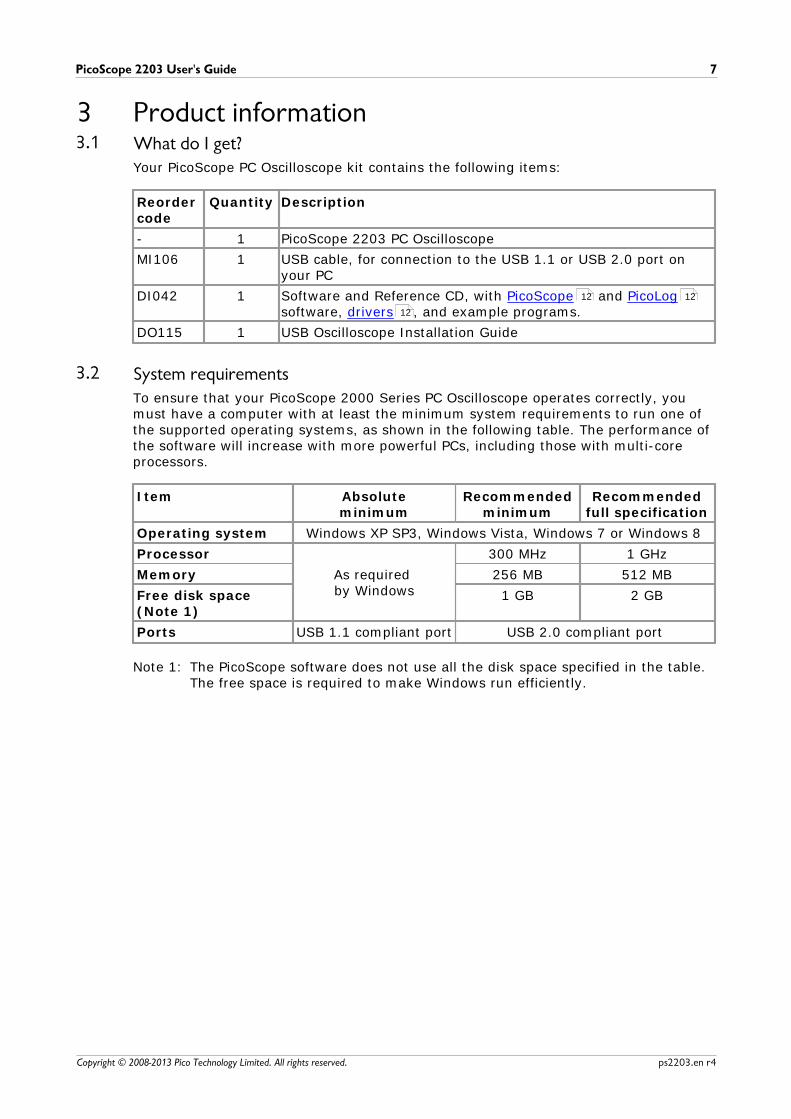
3 Product information3.1 What do I get?
Your PicoScope PC Oscilloscope kit contains the following items:
Reordercode
Quantity Description
- 1 PicoScope 2203 PC Oscilloscope
MI106 1 USB cable, for connection to the USB 1.1 or USB 2.0 port onyour PC
DI042 1 Software and Reference CD, with PicoScope and PicoLogsoftware, drivers , and example programs.
DO115 1 USB Oscilloscope Installation Guide
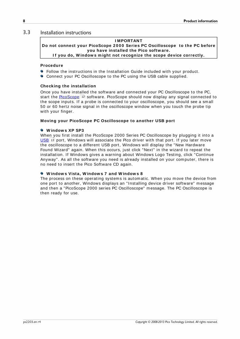
3.2 System requirementsTo ensure that your PicoScope 2000 Series PC Oscilloscope operates correctly, youmust have a computer with at least the minimum system requirements to run one ofthe supported operating systems, as shown in the following table. The performance ofthe software will increase with more powerful PCs, including those with multi-coreprocessors.
Item Absoluteminimum
Recommendedminimum
Recommendedfull specification
Operating system Windows XP SP3, Windows Vista, Windows 7 or Windows 8
Processor
As required by Windows
300 MHz 1 GHz
Memory 256 MB 512 MB
Free disk space (Note 1)
1 GB 2 GB
Ports USB 1.1 compliant port USB 2.0 compliant port
Note 1: The PicoScope software does not use all the disk space specified in the table.The free space is required to make Windows run efficiently.
12 12
12
Product information8
Copyright © 2008-2013 Pico Technology Limited. All rights reserved.ps2203.en r4
3.3 Installation instructions
IMPORTANTDo not connect your PicoScope 2000 Series PC Oscilloscope to the PC before
you have installed the Pico software.If you do, Windows might not recognize the scope device correctly.
Procedure
Follow the instructions in the Installation Guide included with your product.Connect your PC Oscilloscope to the PC using the USB cable supplied.
Checking the installation
Once you have installed the software and connected your PC Oscilloscope to the PC,start the PicoScope software. PicoScope should now display any signal connected tothe scope inputs. If a probe is connected to your oscilloscope, you should see a small50 or 60 hertz noise signal in the oscilloscope window when you touch the probe tipwith your finger.
Moving your PicoScope PC Oscilloscope to another USB port
Windows XP SP3When you first install the PicoScope 2000 Series PC Oscilloscope by plugging it into a USB port, Windows will associate the Pico driver with that port. If you later movethe oscilloscope to a different USB port, Windows will display the "New HardwareFound Wizard" again. When this occurs, just click "Next" in the wizard to repeat theinstallation. If Windows gives a warning about Windows Logo Testing, click "ContinueAnyway". As all the software you need is already installed on your computer, there isno need to insert the Pico Software CD again.
Windows Vista, Windows 7 and Windows 8The process on these operating systems is automatic. When you move the device fromone port to another, Windows displays an "Installing device driver software" messageand then a "PicoScope 2000 series PC Oscilloscope" message. The PC Oscilloscope isthen ready for use.
12
13
PicoScope 2203 User's Guide 9
Copyright © 2008-2013 Pico Technology Limited. All rights reserved. ps2203.en r4
3.4 Connections
3.4.1 Connector diagrams
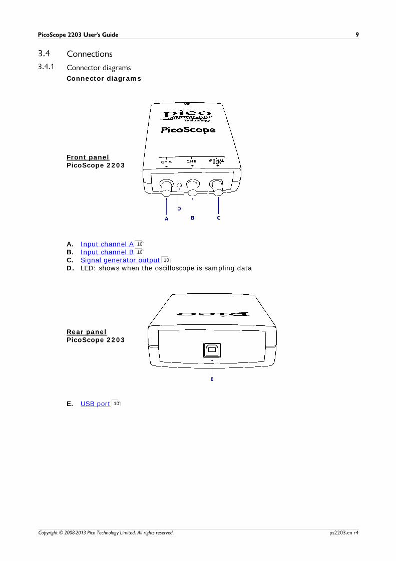
Connector diagrams
Front panelPicoScope 2203
A. Input channel AB. Input channel BC. Signal generator outputD. LED: shows when the oscilloscope is sampling data
Rear panelPicoScope 2203
E. USB port
10
10
10
10
Product information10
Copyright © 2008-2013 Pico Technology Limited. All rights reserved.ps2203.en r4
3.4.2 Signal inputs
The PicoScope 2203 PC Oscilloscope has BNC oscilloscope connectors. The inputs havean impedance of 1 M , so they are compatible with all standard scope probesincluding x10 attenuated types.
3.4.3 Signal Out connector
The SIGNAL OUT connector on the front panel carries the output of the oscilloscope'sbuilt-in signal generator, which can generate a number of built-in waveforms as wellas arbitrary waveforms from a user-defined table of data.
Instructions for use
If you are using the PicoScope 6 program, refer to the PicoScope 6 User's Guide forinformation on how to configure the signal generator.If you are writing your own software, refer to the PicoScope 2000 SeriesProgrammer's Guide.
Signal generator output specifications
Refer to the Specifications table .
3.4.4 USB port
Connect the oscilloscope's USB port to your PC's USB 2.0 port using the USB cablesupplied. You can also connect it to a USB 1.1 port, but in this configuration the oscilloscope will not operate at full performance.
11
PicoScope 2203 User's Guide 11
Copyright © 2008-2013 Pico Technology Limited. All rights reserved. ps2203.en r4
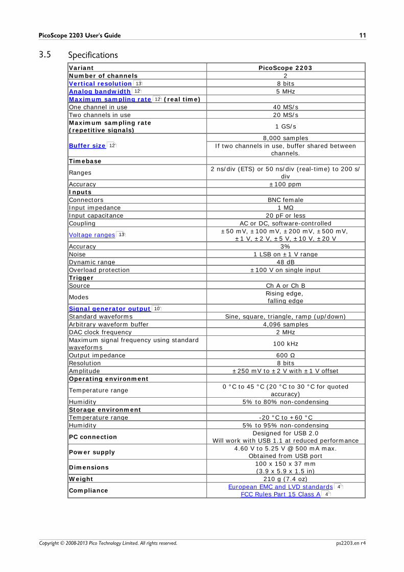
3.5 Specifications
Variant PicoScope 2203
Number of channels 2
Vertical resolution 8 bits
Analog bandwidth 5 MHz
Maximum sampling rate (real time)
One channel in use 40 MS/s
Two channels in use 20 MS/s
Maximum sampling rate(repetitive signals)
1 GS/s
Buffer size8,000 samples
If two channels in use, buffer shared betweenchannels.
Timebase
Ranges2 ns/div (ETS) or 50 ns/div (real-time) to 200 s/
div
Accuracy ±100 ppm
Inputs
Connectors BNC female
Input impedance 1 MΩ
Input capacitance 20 pF or less
Coupling AC or DC, software-controlled
Voltage ranges±50 mV, ±100 mV, ±200 mV, ±500 mV,
±1 V, ±2 V, ±5 V, ±10 V, ±20 V
Accuracy 3%
Noise 1 LSB on ±1 V range
Dynamic range 48 dB
Overload protection ±100 V on single input
Trigger
Source Ch A or Ch B
ModesRising edge, falling edge
Signal generator output
Standard waveforms Sine, square, triangle, ramp (up/down)
Arbitrary waveform buffer 4,096 samples
DAC clock frequency 2 MHz
Maximum signal frequency using standardwaveforms
100 kHz
Output impedance 600 Ω
Resolution 8 bits
Amplitude ±250 mV to ±2 V with ±1 V offset
Operating environment
Temperature range0 °C to 45 °C (20 °C to 30 °C for quoted
accuracy)
Humidity 5% to 80% non-condensing
Storage environment
Temperature range -20 °C to +60 °C
Humidity 5% to 95% non-condensing
PC connectionDesigned for USB 2.0
Will work with USB 1.1 at reduced performance
Power supply4.60 V to 5.25 V @ 500 mA max.
Obtained from USB port
Dimensions100 x 150 x 37 mm(3.9 x 5.9 x 1.5 in)
Weight 210 g (7.4 oz)
ComplianceEuropean EMC and LVD standards
FCC Rules Part 15 Class A
13
12
12
12
13
10
4
4
Glossary12
Copyright © 2008-2013 Pico Technology Limited. All rights reserved.ps2203.en r4
4 GlossaryAnalog bandwidth—The frequency at which the measured signal amplitude is3 decibels below the true signal amplitude.
Block mode—A fast data collection mode. The PicoScope software puts theoscilloscope into this mode to achieve the fastest possible sampling rates. Theoscilloscope collects data as fast as possible and then stops to transfer the data to thePC. During data transfer to the PC in block mode, the oscilloscope cannot sample datafrom its inputs.
Buffer size—The size of the oscilloscope's buffer memory, measured in samples. Thebuffer allows the oscilloscope to sample data faster than it can transfer it to thecomputer.
Coupling mode—To switch from AC coupling to DC coupling, or vice versa, select ACor DC from the control on the PicoScope toolbar. The AC setting filters out very low-frequency components of the input signal, including DC, and is suitable for viewingsmall AC signals superimposed on a DC or slowly changing offset. In this mode youcan measure the peak-to-peak amplitude of an AC signal but not its absolute value.Use the DC setting for measuring the absolute value of a signal.
Device Manager—Device Manager is a Windows program that displays the currenthardware configuration of your computer. On Windows XP or Vista, right-click on 'MyComputer,' choose 'Properties', then click the 'Hardware' tab and the 'Device Manager'button.
Driver—A program that controls a piece of hardware. The driver for the PicoScope2000 Series PC Oscilloscopes is supplied in the form of a 32-bit Windows DLL, ps2000.dll. This is used by the PicoScope software to control the oscilloscope.
ETS—Equivalent Time Sampling. Constructs a picture of a repetitive signal byaccumulating information over many similar wave cycles. This allows the oscilloscopeto create a composite cycle that has more samples, and therefore better timeresolution, than a single cycle. ETS cannot be used for one-shot signals.
Maximum sampling rate—A figure indicating the maximum number of samples theoscilloscope can acquire per second. The higher the sampling rate of the oscilloscope,the more accurate the representation of the high-frequency details in a fast signal."MS/s" is used in this manual an abbreviation for "millions of samples per second".
Oversampling—A technique for reducing noise in sampled signals. Measurements aretaken more frequently than the requested sample rate, and then merged to producethe required number of samples. If, as is usually the case, the signal contains a smallamount of noise, this technique can increase the effective vertical resolution of theoscilloscope.
PC Oscilloscope—A virtual instrument formed by connecting a PicoScope oscilloscopeto a computer running the PicoScope software.
PicoLog software—An application that accompanies all Pico PC Oscilloscopes, turningyour PC into a data logger.
PicoScope software—A software program that accompanies all Pico PCOscilloscopes. It turns your PC into an oscilloscope, spectrum analyser, and meterdisplay.
13
PicoScope 2203 User's Guide 13
Copyright © 2008-2013 Pico Technology Limited. All rights reserved. ps2203.en r4
Signal generator—Generates a waveform and outputs it on the BNC socket markedSignal Out. This output can be used to drive a test signal through a BNC cable into anexternal circuit or into one of the oscilloscope's input channels. The PicoScopesoftware allows the generator to output standard waveforms, such as sine and squarewaves, or arbitrary waveforms defined by the user.
Streaming mode—A data collection mode in which the oscilloscope samples data andreturns it to the computer in a continuous stream. This mode allows the capture ofmore data than will fit in the oscilloscope's memory buffer, at sampling rates up to13.3 million samples per second. The PicoScope program selects this mode for longtimebases to enable the capture of very long sets of data.
Timebase—A timer that controls the speed at which the scope device captures data.At slow timebases this process is visible as PicoScope draws the trace across the scopeview from left to right, but at fast timebases PicoScope draws the whole trace in asingle operation. The timebase is measured in units of time (such as seconds) perdivision. There are ten divisions across the scope view, so the total time across thewidth of the view is ten times the "per division" setting.
USB 1.1—Universal Serial Bus (Full Speed). This is a standard port used to connectexternal devices to PCs. A typical USB 1.1 port supports a data transfer rate of 12megabits per second, so is much faster than an RS-232 or 'COM' port.
USB 2.0—Universal Serial Bus (High Speed). This is a standard port used to connectexternal devices to PCs. A typical USB 2.0 port supports a data transfer rate 40 timesfaster than USB 1.1 when used with a USB 2.0 device, but can also be used with USB1.1 devices.
Vertical resolution—A value, in bits, indicating the precision with which theoscilloscope converts input voltages to digital values. Oversampling (see above) canimprove the effective vertical resolution.
Voltage range—The range of input voltages that the oscilloscope can measure. Forexample, a voltage range of ±100 mV means that the oscilloscope can measurevoltages between -100 mV and +100 mV. Input voltages outside this range will not bemeasured correctly, but will not damage the instrument as long as they remain withinthe protection limits of ±100 V.
Appendix A: Declaration of Conformity14
Copyright © 2008-2013 Pico Technology Limited. All rights reserved.ps2203.en r4
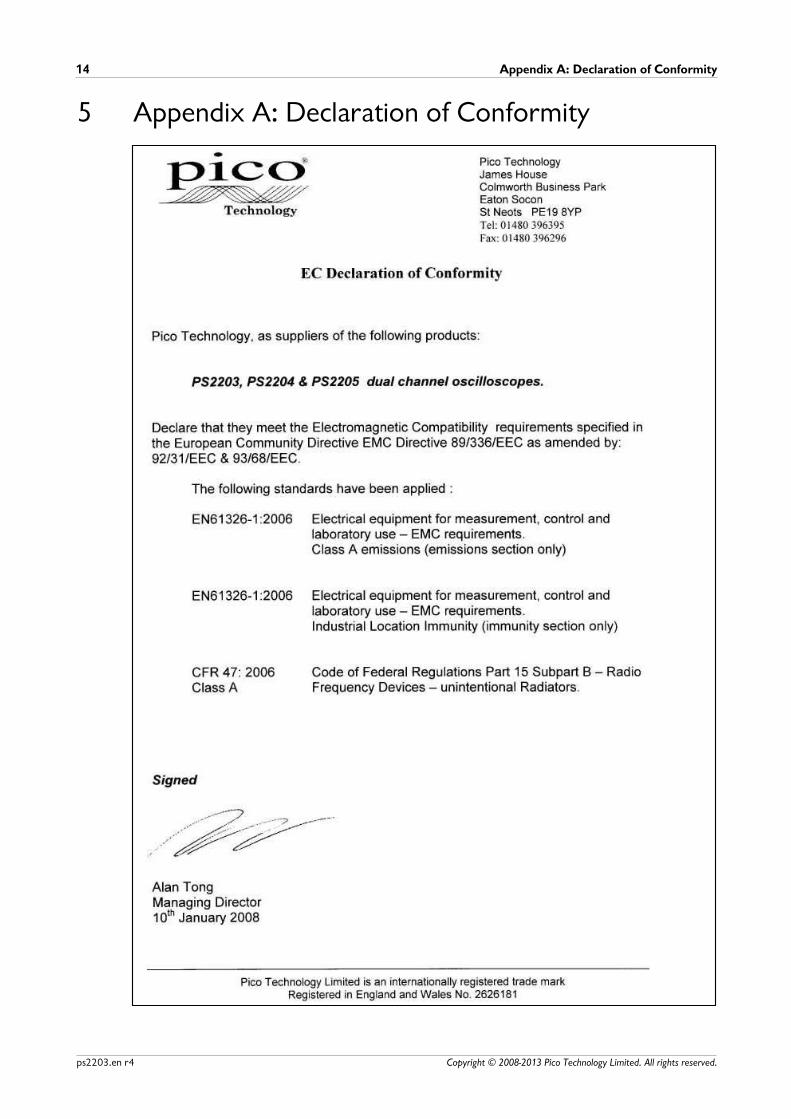
5 Appendix A: Declaration of Conformity
PicoScope 2203 User's Guide 15
Copyright © 2008-2013 Pico Technology Limited. All rights reserved. ps2203.en r4
Index
--20 V 3
AAccuracy
timebase 11
voltage 11
Analog bandwidth 11
Arbitrary waveform generator 10
BBandwidth (analog) 11
BNC connector 10
Buffers
size 11
CCalibration 3
CE notice 4
Company information 6
Compliance 11
Connections 9
Contact details 6
DDimensions 11
Disk space 7
Dynamic range 11
EEMC Directive 4
FFCC notice 4
GGrounding 3
IInput range, maximum 3, 11
Inputs 11
Installation 8
LLED 9
Low Voltage Directive 4
MMains voltages 3
NNoise 11
OOperating environment 11
Operating system 7
Oscilloscope probe 10
Outputs 11
Overload protection 11
PPC connection 11
Pico Technical Support 6
PicoScope 2203 Series 1
PicoScope software 8
Power supply 11
Processor 7
RRepairs 3
Resolution, vertical 11
SSafety
symbols 2
warning 3, 4
Sampling rate 11
Scope probe 10
Signal generator 10, 11
output 10
Signal Out connector 10
Software licence conditions 5
Specifications 11
Storage environment 11
System memory 7
System requirements 7
Index16
Copyright © 2008-2013 Pico Technology Limited. All rights reserved.ps2203.en r4
TTechnical support 6
Test equipment 3
Trademarks 6
Trigger
bandwidth 11
modes 11
source 11
UUSB 7
changing ports 8
USB port 10
VVertical resolution 11
Voltage ranges 11
WWarranty 6
Weight 11
Windows, Microsoft 7

PicoScope 2203 User's Guide 17
Copyright © 2008-2013 Pico Technology Limited. All rights reserved. ps2203.en r4
Pico TechnologyJames House
Colmworth Business ParkST. NEOTS
CambridgeshirePE19 8YP
United KingdomTel: +44 (0) 1480 396 395Fax: +44 (0) 1480 396 296
www.picotech.com
Copyright © 2008-2013 Pico Technology Limited. All rights reserved.ps2203.en r4 26.06.13