Embed Size (px)
Citation preview
Pixel-isolated liquid-crystal mode by using a patterned anisotropic phaseseparation for flexible LCDs
Se-Jin JangJong-Wook JungHak-Rin KimMin Young JinYou-Jin LeeJae-Hoon Kim
Abstract — A pixel-isolated liquid-crystal (PILC) mode for enhancing the mechanical stability of flex-ible-display applications is proposed. Because liquid-crystal (LC) molecules in this mode are isolatedin each pixel by patterned or phase-separated microstructures, and the two substrates are tightlyattached to each other by a solidified polymer layer, the LC alignment is stable against external pres-sure, and the cell gap of our structure is uniformly preserved against bending deformation of the plasticsubstrates. The mechanical stability of the PILC structure having plastic substrates was tested for itselectro-optic properties.
Keywords — Liquid crystal, flexible display, phase separation, pixel-isolated liquid-crystal mode,mode stability.
1 IntroductionIn recent years, roll-up displays have drawn considerableattention for next-generation information displays becauseof their excellent portability, such as light weight, thin pack-aging, and flexibility. Among several available technologies,it is expected that a liquid-crystal display (LCD) using plas-tic film substrates is the most promising device because ofits superior visibility with low power consumption overother displays, such as organic light-emitting devices orelectrophoretic displays. However, there are still majorproblems in fabricating commercially available plasticLCDs with current technologies based on glass substrates.One of those problems is the instability of LC structures dueto the hydrodynamic properties of LCs at bending. Theseparation of two plastic substrates due to the flexibility isalso a problem that needs to be solved. Such problems donot exist in conventional glass-substrate-based LCDs becauseglass substrates can sustain a stable LC-alignment conditionagainst external bending or pressure.
To solve these problems, several types of polymerwalls and/or networks as supporting structures have beenproposed and demonstrated.1–9 These structures were fab-ricated using an anisotropic phase-separation method frompolymer and LC composite systems by applying a patternedelectric field1 or spatially modulated UV intensity.2,3,8 How-ever, these methods require a high electric field to initiatethe anisotropic phase separation or remain residual poly-mers in unexposed regions that reduce optical propertiesand increase the operating voltage of the devices.1–3 More-over, these methods are not appropriate for a cost-effectiveroll-to-roll process, which is essential in fabricating large-area plastic LCDs. Thus, an alternate fabrication methodshould be developed in order for plastic LCDs to be com-mercialized.
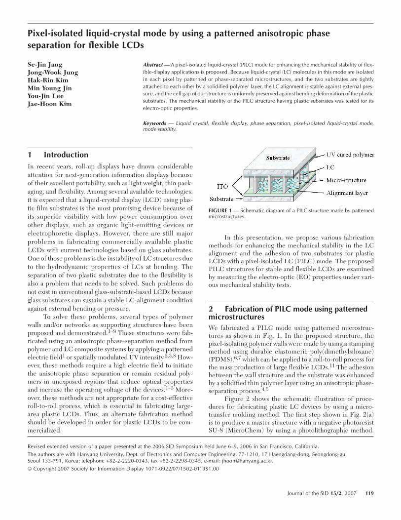
In this presentation, we propose various fabricationmethods for enhancing the mechanical stability in the LCalignment and the adhesion of two substrates for plasticLCDs with a pixel-isolated LC (PILC) mode. The proposedPILC structures for stable and flexible LCDs are examinedby measuring the electro-optic (EO) properties under vari-ous mechanical stability tests.
2 Fabrication of PILC mode using patternedmicrostructuresWe fabricated a PILC mode using patterned microstruc-tures as shown in Fig. 1. In the proposed structure, thepixel-isolating polymer walls were made by using a stampingmethod using durable elastomeric poly(dimethylsiloxane)(PDMS),6,7 which can be applied to a roll-to-roll process forthe mass production of large flexible LCDs.11 The adhesionbetween the wall structure and the substrate was enhancedby a solidified thin polymer layer using an anisotropic phase-separation process.4,5
Figure 2 shows the schematic illustration of proce-dures for fabricating plastic LC devices by using a micro-transfer molding method. The first step shown in Fig. 2(a)is to produce a master structure with a negative photoresistSU-8 (MicroChem) by using a photolithographic method.
Revised extended version of a paper presented at the 2006 SID Symposium held June 6–9, 2006 in San Francisco, California.
The authors are with Hanyang University, Dept. of Electronics and Computer Engineering, 77-1210, 17 Haengdang-dong, Seongdong-gu,Seoul 133-791, Korea; telephone +82-2-2220-0343, fax +82-2-2298-0345, e-mail: [email protected].
© Copyright 2007 Society for Information Display 1071-0922/07/1502-0119$1.00
FIGURE 1 — Schematic diagram of a PILC structure made by patternedmicrostructures.
Journal of the SID 15/2, 2007 119
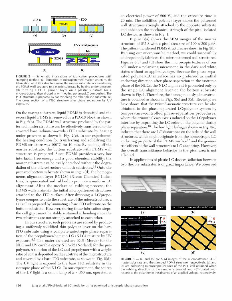
On the master substrate, liquid PDMS is deposited and theexcess liquid PDMS is removed by a PDMS block, as shownin Fig. 2(b). The PDMS wall structure produced by the pat-terned master structure can be effectively transferred to thecovered bare indium-tin-oxide (ITO) substrate by heatingunder pressure, as shown in Fig. 2(c). In our experiment,the heating condition for transferring and solidifying thePDMS structure was 100°C for 10 min. By peeling off themaster substrate, the bottom substrate with PDMS wallstructures is prepared. Since PDMS provides a very lowinterfacial free energy and a good chemical stability, themaster substrate can be easily detached without the degra-dation of the microstructure on both substrates.11 Onto theprepared bottom substrate shown in Fig. 2(d), the homoge-neous alignment layer RN1286 (Nissan Chemical Indus-tries) is spin-coated and rubbed to promote a uniform LCalignment. After the mechanical rubbing process, thePDMS walls maintain the initial micropatterned structuresattached to the ITO surface. After dropping a LC/prepo-lymer composite onto the substrate of the microstructure, aLC cell is prepared by laminating a bare ITO substrate on thebottom substrate. However, during these fabrication steps,the cell gap cannot be stably sustained at bending since thetwo substrates are not strongly attached to each other.
In our structure, such problems are solved by produc-ing a uniformly solidified thin polymer layer on the bareITO substrate using a complete anisotropic phase separa-tion of the prepolymer/nematic LC (NLC) mixture by UVexposure.4,5 The materials used are E48 (Merck) for theNLC and UV curable epoxy NOA-72 (Norland) for the pre-polymer. A solution of the LC and prepolymer with a weightratio of 95:5 is deposited on the substrate of the microstructureand covered by a bare ITO substrate, as shown in Fig. 2(d).The UV light is exposed to the bare ITO substrate in theisotropic phase of the NLCs. In our experiment, the sourceof the UV light is a xenon lamp of λ = 350 nm, operated at
an electrical power of 200 W, and the exposure time is20 min. The solidified polymer layer makes the patternedwall structures strongly attached to the opposite substrateand enhances the mechanical strength of the pixel-isolatedLC device, as shown in Fig. 1.
Figure 3(a) shows the SEM images of the masterstructure of SU-8 with a pixel-area size of 100 × 300 µm2.The pattern-transferred PDMS structures are shown in Fig. 3(b).By using our microtransfer method, we could successfullyand repeatedly fabricate the micropatterned wall structures.Figures 3(c) and (d) show the microscopic textures of ourcell under a polarizing microscope in the dark and whitestates without an applied voltage. Because the phase-sepa-rated polymer/LC interface has no preferred azimuthalanchoring direction after phase separation in the isotropicphase of the NLCs, the NLC alignment is promoted only bythe single LC alignment layer on the bottom substrateshown in Fig. 1. Therefore, the homogeneously planar struc-ture is obtained as shown in Figs. 3(c) and 3(d). Recently, wehave shown that the twisted-nematic structure can be alsoobtained in the phase-separated LC/polymer system bytemperature-controlled phase-separation procedures,where the azimuthal easy axis is induced on the LC/polymerinterface by imprinting the LC order on the polymer duringphase separation.10 The low light leakages shown in Fig. 3(c)indicate that there are LC distortions on the side of the wallstructures, which might originate from the homeotropic LCanchoring property of the PDMS surface12 and the geome-tric effects of the wall structures to LC anchoring. However,the overall transmittance behavior in the pixel area is notaffected.
In applications of plastic LC devices, adhesion betweentwo flexible substrates is of great importance. We observed
FIGURE 2 — Schematic illustrations of fabrication procedures withstamping method: (a) formation of micropatterned master structure, (b)fabrication of PDMS structure using the master substrate, (c) transferringthe PDMS wall structure to a plastic substrate by baking under pressure,(d) forming a LC alignment layer on a plastic substrate for amicrostructure, then dropping or injecting polymer/LC composites. ThePILC structure is prepared by sandwiching the other plastic substrate. (e)The cross section of a PILC structure after phase separation by UVexposure.
FIGURE 3 — (a) and (b) are SEM images of the micropatterned SU-8master substrate and the stamped PDMS structure, respectively. (c) and(d) are polarizing microscopic textures of the PILC cell obtained whenthe rubbing direction of the sample is parallel and 45°-rotated withrespect to the polarizer in the absence of an applied voltage, respectively.
120 Jang et al. / Pixel-isolated LC mode by using patterned anisotropic phase separation
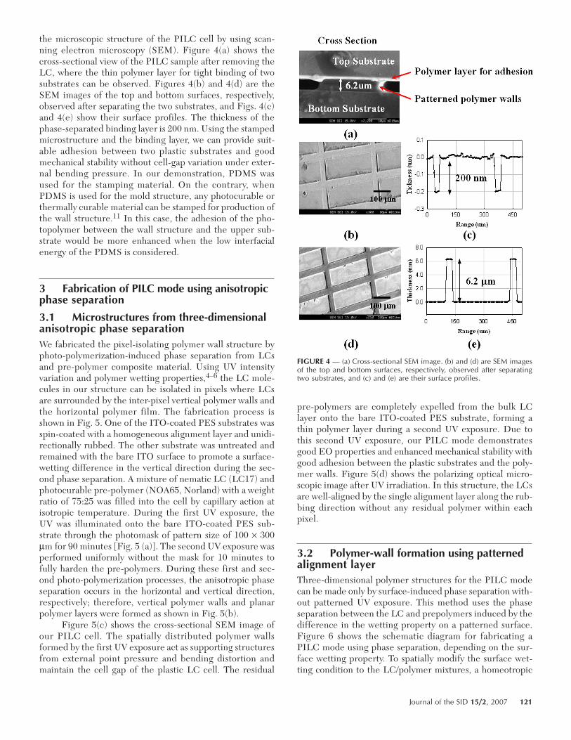
the microscopic structure of the PILC cell by using scan-ning electron microscopy (SEM). Figure 4(a) shows thecross-sectional view of the PILC sample after removing theLC, where the thin polymer layer for tight binding of twosubstrates can be observed. Figures 4(b) and 4(d) are theSEM images of the top and bottom surfaces, respectively,observed after separating the two substrates, and Figs. 4(c)and 4(e) show their surface profiles. The thickness of thephase-separated binding layer is 200 nm. Using the stampedmicrostructure and the binding layer, we can provide suit-able adhesion between two plastic substrates and goodmechanical stability without cell-gap variation under exter-nal bending pressure. In our demonstration, PDMS wasused for the stamping material. On the contrary, whenPDMS is used for the mold structure, any photocurable orthermally curable material can be stamped for production ofthe wall structure.11 In this case, the adhesion of the pho-topolymer between the wall structure and the upper sub-strate would be more enhanced when the low interfacialenergy of the PDMS is considered.
3 Fabrication of PILC mode using anisotropicphase separation
3.1 Microstructures from three-dimensionalanisotropic phase separationWe fabricated the pixel-isolating polymer wall structure byphoto-polymerization-induced phase separation from LCsand pre-polymer composite material. Using UV intensityvariation and polymer wetting properties,4–6 the LC mole-cules in our structure can be isolated in pixels where LCsare surrounded by the inter-pixel vertical polymer walls andthe horizontal polymer film. The fabrication process isshown in Fig. 5. One of the ITO-coated PES substrates wasspin-coated with a homogeneous alignment layer and unidi-rectionally rubbed. The other substrate was untreated andremained with the bare ITO surface to promote a surface-wetting difference in the vertical direction during the sec-ond phase separation. A mixture of nematic LC (LC17) andphotocurable pre-polymer (NOA65, Norland) with a weightratio of 75:25 was filled into the cell by capillary action atisotropic temperature. During the first UV exposure, theUV was illuminated onto the bare ITO-coated PES sub-strate through the photomask of pattern size of 100 × 300µm for 90 minutes [Fig. 5 (a)]. The second UV exposure wasperformed uniformly without the mask for 10 minutes tofully harden the pre-polymers. During these first and sec-ond photo-polymerization processes, the anisotropic phaseseparation occurs in the horizontal and vertical direction,respectively; therefore, vertical polymer walls and planarpolymer layers were formed as shown in Fig. 5(b).
Figure 5(c) shows the cross-sectional SEM image ofour PILC cell. The spatially distributed polymer wallsformed by the first UV exposure act as supporting structuresfrom external point pressure and bending distortion andmaintain the cell gap of the plastic LC cell. The residual
pre-polymers are completely expelled from the bulk LClayer onto the bare ITO-coated PES substrate, forming athin polymer layer during a second UV exposure. Due tothis second UV exposure, our PILC mode demonstratesgood EO properties and enhanced mechanical stability withgood adhesion between the plastic substrates and the poly-mer walls. Figure 5(d) shows the polarizing optical micro-scopic image after UV irradiation. In this structure, the LCsare well-aligned by the single alignment layer along the rub-bing direction without any residual polymer within eachpixel.
3.2 Polymer-wall formation using patternedalignment layerThree-dimensional polymer structures for the PILC modecan be made only by surface-induced phase separation with-out patterned UV exposure. This method uses the phaseseparation between the LC and prepolymers induced by thedifference in the wetting property on a patterned surface.Figure 6 shows the schematic diagram for fabricating aPILC mode using phase separation, depending on the sur-face wetting property. To spatially modify the surface wet-ting condition to the LC/polymer mixtures, a homeotropic
FIGURE 4 — (a) Cross-sectional SEM image. (b) and (d) are SEM imagesof the top and bottom surfaces, respectively, observed after separatingtwo substrates, and (c) and (e) are their surface profiles.
Journal of the SID 15/2, 2007 121
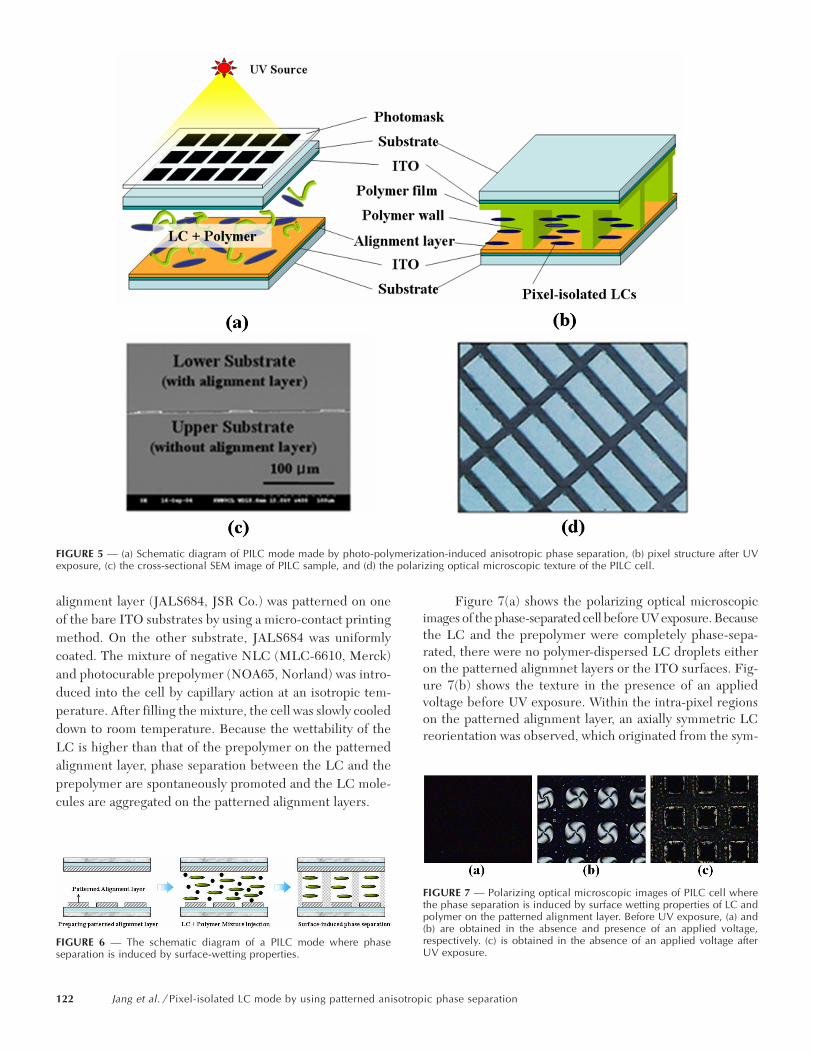
alignment layer (JALS684, JSR Co.) was patterned on oneof the bare ITO substrates by using a micro-contact printingmethod. On the other substrate, JALS684 was uniformlycoated. The mixture of negative NLC (MLC-6610, Merck)and photocurable prepolymer (NOA65, Norland) was intro-duced into the cell by capillary action at an isotropic tem-perature. After filling the mixture, the cell was slowly cooleddown to room temperature. Because the wettability of theLC is higher than that of the prepolymer on the patternedalignment layer, phase separation between the LC and theprepolymer are spontaneously promoted and the LC mole-cules are aggregated on the patterned alignment layers.
Figure 7(a) shows the polarizing optical microscopicimages of the phase-separated cell before UV exposure. Becausethe LC and the prepolymer were completely phase-sepa-rated, there were no polymer-dispersed LC droplets eitheron the patterned alignmnet layers or the ITO surfaces. Fig-ure 7(b) shows the texture in the presence of an appliedvoltage before UV exposure. Within the intra-pixel regionson the patterned alignment layer, an axially symmetric LCreorientation was observed, which originated from the sym-
FIGURE 6 — The schematic diagram of a PILC mode where phaseseparation is induced by surface-wetting properties.
FIGURE 7 — Polarizing optical microscopic images of PILC cell wherethe phase separation is induced by surface wetting properties of LC andpolymer on the patterned alignment layer. Before UV exposure, (a) and(b) are obtained in the absence and presence of an applied voltage,respectively. (c) is obtained in the absence of an applied voltage afterUV exposure.
FIGURE 5 — (a) Schematic diagram of PILC mode made by photo-polymerization-induced anisotropic phase separation, (b) pixel structure after UVexposure, (c) the cross-sectional SEM image of PILC sample, and (d) the polarizing optical microscopic texture of the PILC cell.
122 Jang et al. / Pixel-isolated LC mode by using patterned anisotropic phase separation
metric boundary condition produced by the uncured prepo-lymer in the inter-pixel regions. In this method, only a one-step UV exposure is required for producing the PILC mode.To harden the prepolymers and to fix the phase-separatedpattern, we performed UV irradiation without photomask-ing. Figure 7(c) shows the resultant texture in the absenceof an applied voltage, where the LC molecules are isolatedpolymer microwall structures.
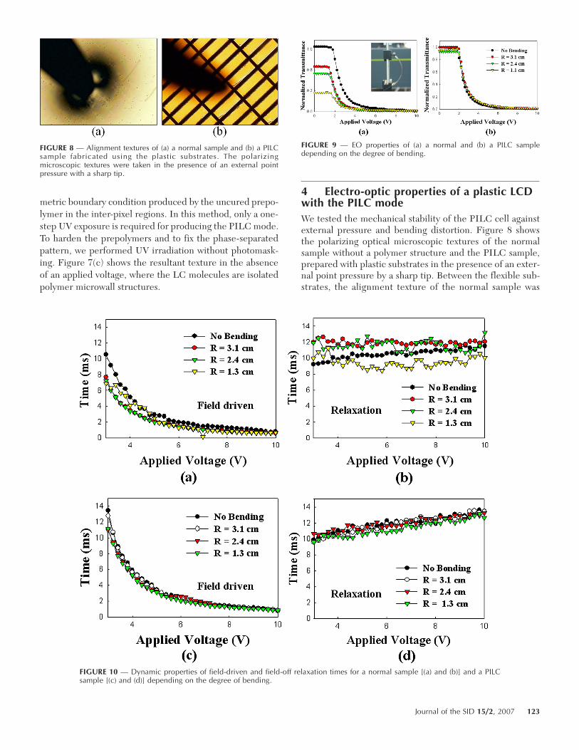
4 Electro-optic properties of a plastic LCDwith the PILC modeWe tested the mechanical stability of the PILC cell againstexternal pressure and bending distortion. Figure 8 showsthe polarizing optical microscopic textures of the normalsample without a polymer structure and the PILC sample,prepared with plastic substrates in the presence of an exter-nal point pressure by a sharp tip. Between the flexible sub-strates, the alignment texture of the normal sample was
FIGURE 8 — Alignment textures of (a) a normal sample and (b) a PILCsample fabricated using the plastic substrates. The polarizingmicroscopic textures were taken in the presence of an external pointpressure with a sharp tip.
FIGURE 9 — EO properties of (a) a normal and (b) a PILC sampledepending on the degree of bending.
FIGURE 10 — Dynamic properties of field-driven and field-off relaxation times for a normal sample [(a) and (b)] and a PILCsample [(c) and (d)] depending on the degree of bending.
Journal of the SID 15/2, 2007 123
severely degraded by the distortion of the LC alignment dueto cell-gap variation in a relatively large area as shown in Fig.8(a). However, that of the PILC sample showed noappreciable changes because the distortion of the LC align-ment was restricted and the cell gap was sustained by thepolymer-wall structure, where the polymer-wall structuresare shown as dark lines in Fig. 8(b).
Figure 9 shows the EO properties of a normal plasticLC cell and the plastic PILC cell in the presence of an externalbending pressure controlled by a pair of linear stages, whereR represents the curvature of bending radius. As the bend-ing stress on the normal plastic LC cell increases, the LCmolecules are severely distorted and the cell gap isdecreased, which resulted in the decrease of the transmit-tance as shown in Fig. 9(a). However, the PILC cell showsalmost the same transmittance properties irrespective of thedegree of the bending pressure over the entire operating-voltage range. Notice that the transmittances shown inFig. 9(a) are degraded by about 70% when the bending dis-tortion was increased to R = 1.1 cm.
Figure 10 shows the dynamic properties of field-driven and field-off relaxation times for the normal sampleand the PILC sample, depending on the degree of bending,respectively. The dynamic properties of the normal sampleshowed much variation due to the cell-gap variation underbending distortion, whereas the PILC mode showed stabledynamic properties.
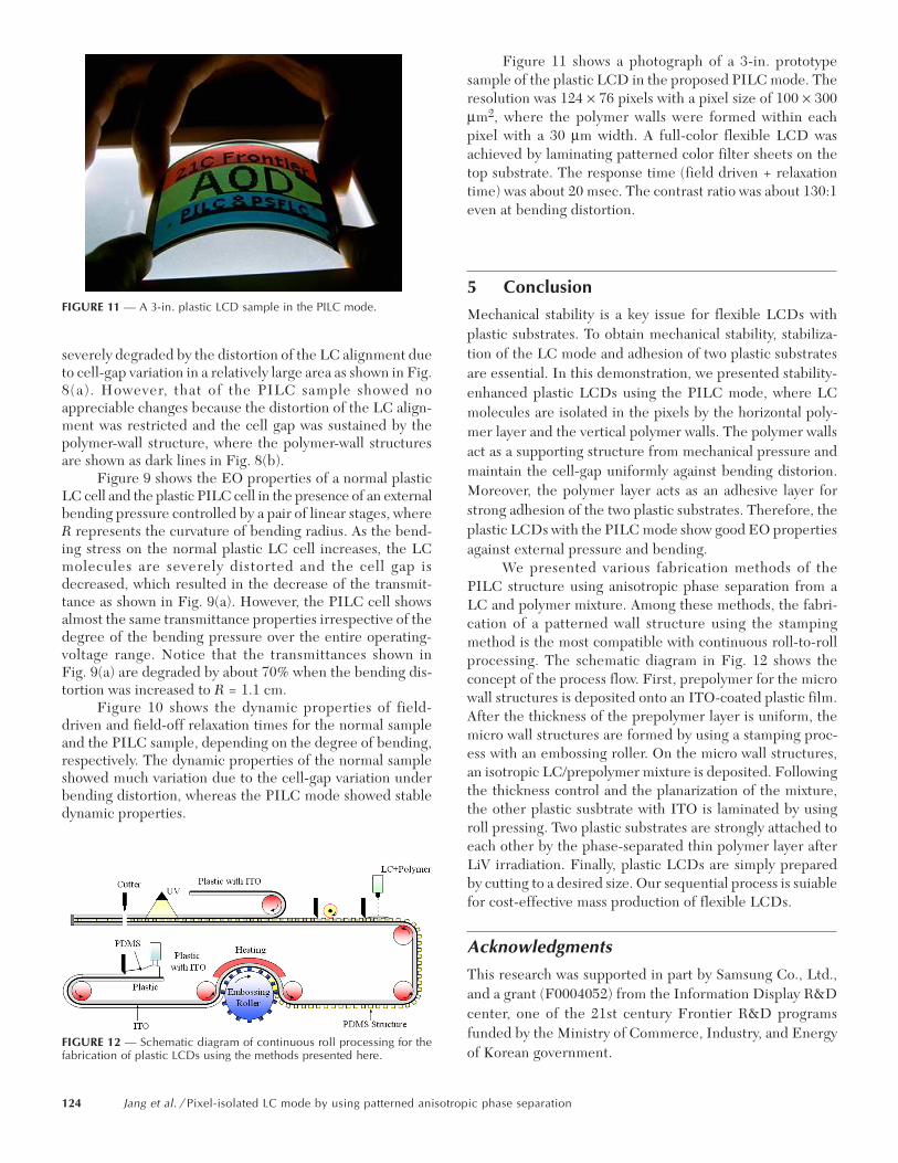
Figure 11 shows a photograph of a 3-in. prototypesample of the plastic LCD in the proposed PILC mode. Theresolution was 124 × 76 pixels with a pixel size of 100 × 300µm2, where the polymer walls were formed within eachpixel with a 30 µm width. A full-color flexible LCD wasachieved by laminating patterned color filter sheets on thetop substrate. The response time (field driven + relaxationtime) was about 20 msec. The contrast ratio was about 130:1even at bending distortion.
5 Conclusion
Mechanical stability is a key issue for flexible LCDs withplastic substrates. To obtain mechanical stability, stabiliza-tion of the LC mode and adhesion of two plastic substratesare essential. In this demonstration, we presented stability-enhanced plastic LCDs using the PILC mode, where LCmolecules are isolated in the pixels by the horizontal poly-mer layer and the vertical polymer walls. The polymer wallsact as a supporting structure from mechanical pressure andmaintain the cell-gap uniformly against bending distorion.Moreover, the polymer layer acts as an adhesive layer forstrong adhesion of the two plastic substrates. Therefore, theplastic LCDs with the PILC mode show good EO propertiesagainst external pressure and bending.
We presented various fabrication methods of thePILC structure using anisotropic phase separation from aLC and polymer mixture. Among these methods, the fabri-cation of a patterned wall structure using the stampingmethod is the most compatible with continuous roll-to-rollprocessing. The schematic diagram in Fig. 12 shows theconcept of the process flow. First, prepolymer for the microwall structures is deposited onto an ITO-coated plastic film.After the thickness of the prepolymer layer is uniform, themicro wall structures are formed by using a stamping proc-ess with an embossing roller. On the micro wall structures,an isotropic LC/prepolymer mixture is deposited. Followingthe thickness control and the planarization of the mixture,the other plastic susbtrate with ITO is laminated by usingroll pressing. Two plastic substrates are strongly attached toeach other by the phase-separated thin polymer layer afterLiV irradiation. Finally, plastic LCDs are simply preparedby cutting to a desired size. Our sequential process is suiablefor cost-effective mass production of flexible LCDs.
AcknowledgmentsThis research was supported in part by Samsung Co., Ltd.,and a grant (F0004052) from the Information Display R&Dcenter, one of the 21st century Frontier R&D programsfunded by the Ministry of Commerce, Industry, and Energyof Korean government.
FIGURE 11 — A 3-in. plastic LCD sample in the PILC mode.
FIGURE 12 — Schematic diagram of continuous roll processing for thefabrication of plastic LCDs using the methods presented here.
124 Jang et al. / Pixel-isolated LC mode by using patterned anisotropic phase separation
References1 Y Kim, J Francl, B Taheri, and J L West, “A method for the formation
of polymer walls in liquid crystal/polymer mixtures,” Appl Phys Lett72, 2253–2255 (1998).
2 H Sato, H Fujikake, Y Iino, M Kawakita, and H Kikuchi, “Flexiblegrayscale ferroelectric liquid crystal device containing polymer wallsand networks,” Jpn J Appl Phys 41, 5302–5306 (2002).
3 H S Kitzerow, H Molsen, and G Heppke, “Linear electro-optic effectsin polymer-dispersed ferroelectric liquid crystals,” Appl Phys Lett 60,3093–3095 (1992).
4 V Vorflusev and S Kumar, “Phase-separated composite films for liquidcrystal displays,” Science 283, 1903–1905 (1999).
5 T Qian, J-H Kim, S Kumar, and P L Taylor, “Phase-separated compositefilms: Experiment and theory,” Phys Rev E 61, 4007–4010 (2000).
6 J-W Jung, S-K Park, S-B Kwon, and J-H Kim, “Pixel-isolated liquidcrystal mode for flexible display applications,” Jpn J Appl Phys 43,4269–4272 (2004).
7 S-J Jang, J-W Jung, H-R Kim, M Y Jin, and J-H Kim, “Stability-enhancedpixel isolation method for flexible liquid crystal displays,” Jpn J ApplPhys 44, 6670–6673 (2005).
8 R Penterman, S I Klink, H de Koning, G Nisato, and D J Broer,“Single-substrate liquid crystal displays by photo-enforced stratifica-tion,” Nature 417, 55–58 (2002).
9 J P A Vogels, S I Klink, R Penterman, H de Koning, E E A Huitema,and D J Broer, “Robust flexible LCDs with paintable technology,” J SocInfo Display 12, 411–416 (2004).
10 H-R Kim, J-W Jung, Y-J Lee, and J-H Kim, “Liquid-crystal alignmentwith a molecular template of imprinted polymer layer during phaseseparation,” Appl Phys Lett 88, 113504 (2006).
11 Y Xia and G M Whitesides, “Soft Lithography,” Angew Chem Int Ed37, 550–575 (1998).
12 Y-T Kim, J-H Hong, T-Y Yoon, and S-D Lee, “Pixel-encapsulatedflexible displays with a multi-functional elastomer substrate for self-aligning liquid crystals,” Appl Phys Lett 88, 263501 (2006).
13 J-W Jung, M Y Jin, H-R Kim, Y-J Lee, and J-H Kim, “Mechanicalstability of pixel-isolated liquid crystal mode with plastic substrates,”Jpn J Appl Phys 44, 8547 (2005).
Se-Jin Jang received his B.S. degree in physicsfrom Hallym University, Korea, in 2003, and hisM.S. degree in information display engineeringfrom Hanyang University, Korea, in 2006. Hisresearch activities include the device physics ofliquid crystal, flexible displays, and soft-lithography.
Jong-Wook Jung received his B.S. degree in phys-ics from Hallym University, Korea, in 2003 andhis M.S. degree in information-display engineer-ing from Hanyang University, Korea, in 2006. Hisresearch activities include the device physics ofliquid-crystal and flexible displays.
Hak-Rin Kim recieved his B.S., M.S., and Ph.D.degrees in electrical engineering from Seoul NationalUniversity, Korea, in 1998, 2000, and 2005, respec-tively. In 2005, he became a research associate ofthe Research Institute of Information Display,Hanyang University. His research activities includedevice physics of liquid crystals, flexible displays,and flexible electronics.
Min Young Jin received his B.S. degree in physicsin February 1988 from Chung-Ang University andhis M.S. and Ph.D. degrees in 1995 and 2001from the Korea Advanced Institute of Science andTechnology, respectively. Since January, he wassenior research engineer with Iljin Display Business.Since December 2004, he has been a researchassociate with the Division of Electrical and ComputerEngineering at Hanyang University. His researchactivities include the device physics of liquid
crystals and its mixtures, flexible displays, and surface/interface control.
You-Jin Lee received her B.S. and M.S. degrees inphysics from Sogang University, Korea, in 1992and 1994, respectively. From 1994 to 2005, shewas with Samsung SDI, Giheung, Korea, whereshe was involved in the development of ferroelec-tric liquid-crystal displays. In 2005, she joined theDepartment of Information Display Engineering ofHanyang University, Seoul, Korea, as a Ph.D. can-didate. Her main research interests include flex-ible displays and display devices using liquidcrystals.
Jae-Hoon Kim received his B.S. degree fromSogang University, Seoul, Korea, in 1987, his M.S.degree from the University of Oregon, Eugene,and the Ph.D. degree from Sogang University, in1996, all in physics. He formerly worked at theLiquid Crystal Institute, Kent State University,Kent, OH, as a Research Associate from 1996 to1999. From 1999 to 2000, he was with SamsungElectronics, Giheung, Korea, where he was involvedin the development of patterned vertical align-ment liquid-crystal displays. In 2000, he joined
the Department of Physics of Hallym University, Chuncheon, Korea, asan Assistant Professor. Since March 2004, he has been an Associate Pro-fessor in the Division of Electrical and Computer Engineering, HanyangUniversity, Seoul, Korea. His main research interests include display andphotonic devices using liquid crystals.
Journal of the SID 15/2, 2007 125