Embed Size (px)
Citation preview
Best Practice Guidance to
Planning Policy Statement 18 ‘Renewable Energy’
August 2009
Planning and Environmental Policy Group

Best Practice Guidance to Planning Policy Statement 18 ‘Renewable Energy’
Planning Policy Statement 18 ‘Renewable Energy’ (PPS18) sets out the Department’s planning policy for development that generates energy from renewable resources and that requires the submission of a planning application. The information contained in this guide should be read in conjunction with PPS 18.
Planning and Environmental Policy Group Calvert House 23 Castle Place BELFAST BT1 1FY
August 2009

Contents Preamble .........................................................................................................1 1. WIND ENERGY.......................................................................................3
Introduction..............................................................................................3 Technology..............................................................................................3 Planning Issues .....................................................................................11 Information To Accompany A Planning Application...............................31 Other Authorisations/Consents..............................................................32 Consultees ............................................................................................33
2. BIOMASS ..............................................................................................35
Introduction............................................................................................35 Technology............................................................................................36 Planning Issues .....................................................................................44 Information To Accompany A Planning Application...............................44 Other Authorisations/Consents..............................................................45
3. ENERGY FROM WASTE (BIOLOGICAL PROCESSES)......................46
Introduction............................................................................................46 Technology............................................................................................48 Planning Issues .....................................................................................53 Information To Accompany A Planning Application...............................56 Other Authorisations/Consents..............................................................57
4. ENERGY FROM WASTE (THERMAL PROCESSES) ..........................58
Introduction............................................................................................58 Technology............................................................................................59 Planning Issues .....................................................................................62 Information To Accompany A Planning Application...............................63 Other Authorisations/Consents..............................................................64
5. SMALL HYDRO.....................................................................................65
Introduction............................................................................................65 Technology............................................................................................65 Planning Issues .....................................................................................67 Information To Accompany A Planning Application...............................70 Other Authorisations/Consents..............................................................71
6. ACTIVE SOLAR (PHOTOVOLTAICS)...................................................72
Introduction............................................................................................72 Technology............................................................................................72 Planning Issues .....................................................................................74 Information To Accompany A Planning Application...............................75 Other Authorisations/Consents..............................................................75
7. SOLAR THERMAL (SOLAR WATER HEATING) ..................................76 Introduction............................................................................................76 Technology............................................................................................76 Planning Issues .....................................................................................78 Information To Accompany A Planning Application...............................79 Other Authorisations/Consents..............................................................80
8. GROUND, WATER AND AIR SOURCE HEAT PUMPS........................81
Ground Source Heat Pumps .................................................................81 Introduction............................................................................................81 Technology............................................................................................81 Planning Issues .....................................................................................82 Water Source Heat Pumps....................................................................83 Air Source Heat Pumps .........................................................................83
9. PASSIVE SOLAR DESIGN ...................................................................85
Introduction............................................................................................85 Technology............................................................................................85 Planning Issues .....................................................................................87 Information To Accompany A Planning Application...............................88 Other Authorisations/Consents..............................................................89
Preamble This guide provides background information on the various renewable energy technologies that may come forward in Northern Ireland and is designed to contribute to the development management process. It has been drawn up taking account of similar material available for other parts of the UK and the Republic of Ireland. This includes: • Scottish Executive Planning Advice Note 45, Renewable Energy
Technologies (2002); • the technical annex to the Companion Guide to Planning Policy Statement
22 issued by the Office of the Deputy Prime Minister (2004); • Planning Policy Wales, Technical Advice Note 8: Planning for Renewable
Energy (2005); and • Wind Energy Development Guidelines, Department of the Environment,
Heritage and Local Government (Ireland) (2006). The advice and guidance contained within this guide should be read in conjunction with Planning Policy Statement 18 ‘Renewable Energy’ which sets out the Department’s planning policy for development that generates energy from renewable resources and that requires the submission of a planning application.
1

2
1. Wind energy
INTRODUCTION 1.1.1 This section describes the technology of wind turbines in relation to
current turbine sizes (600kW-3MW) that are expected to comprise the bulk of the UK’s onshore wind generated electricity provision. In most respects this information will be equally valid for both smaller wind turbines, more suited to locations with higher population densities, and the larger machines that will be developed in the coming years. Where there are differences these will be clearly noted. The section discusses only land-based turbines, although there is essentially little difference between these and machines that are installed off-shore.
1.1.2 A typical wind energy development may include the following elements:
Wind turbines - Wind monitoring mast - Transformers Serving each turbine Internal tracks and crane pads
Giving access to the turbines
Substation compound Including transformers, circuit breakers and control building
Power cables Usually underground within the site Poles/pylons Connecting wind energy development
site to the national grid Other associated infrastructure and development
Wind monitoring masts, site entrance, temporary contractors compound and borrow pits
TECHNOLOGY 1.2.1 There are essentially two types of wind turbine – those that have rotors
that rotate about a vertical axis, and horizontal axis machines whose rotating shafts are aligned horizontally. Most wind turbines installed today are of the latter type and this is likely to remain the case for the foreseeable future. The remainder of this section refers primarily to horizontal axis machines.
1.2.2 Whilst wind turbines are sometimes used to generate mechanical
power, particularly for pumping water, this section deals only with the electricity producing variety. Such wind turbines convert the kinetic energy of the wind that passes through the swept area of the rotor into electrical energy by means of a rotor (generally comprising 3 blades), a mechanical drive train (usually including a gearbox) and an electrical generator. These are all mounted on a tower. The blades need to be far enough from the ground to minimise turbulence and to maximise
3

the energy capture of the wind turbine. Normally solid tubular towers are used rather than lattice constructed towers.
1.2.3 Wind turbines are defined by the size (diameter) of the rotor and rated
power or capacity in kW (kW) or megawatts (MW). The rated capacity of a wind turbine is a measure of the maximum output of the electricity generator which will generally be achieved in wind speeds greater than 12-15m/s at the hub height of the rotor. There are two things worth noting: • an increase in the rotor diameter of a wind turbine will result in a
greater than proportional change in rated power (see figure 1); • an increase in wind speed will result in a greater than proportional
change in rated power. Rated power is proportional to the cube of the wind speed, and hence a doubling of wind speed will result in a roughly eight-fold increase in power output.
1.2.4 Technological advances have led to a wide range of wind turbine
designs. The smallest turbines, some with a rotor diameter of less than one metre, are usually used for charging batteries although recent mains-connected micro-turbines have been introduced to the market. At the other end of the scale, turbines with rotor diameters of greater than 100m are now being deployed.
4
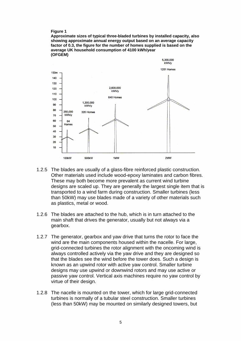
Figure 1 Approximate sizes of typical three-bladed turbines by installed capacity, also showing approximate annual energy output based on an average capacity factor of 0.3, the figure for the number of homes supplied is based on the average UK household consumption of 4100 kWh/year (OFGEM)
1.2.5 The blades are usually of a glass-fibre reinforced plastic construction.
Other materials used include wood-epoxy laminates and carbon fibres. These may both become more prevalent as current wind turbine designs are scaled up. They are generally the largest single item that is transported to a wind farm during construction. Smaller turbines (less than 50kW) may use blades made of a variety of other materials such as plastics, metal or wood.
1.2.6 The blades are attached to the hub, which is in turn attached to the
main shaft that drives the generator, usually but not always via a gearbox.
1.2.7 The generator, gearbox and yaw drive that turns the rotor to face the
wind are the main components housed within the nacelle. For large, grid-connected turbines the rotor alignment with the oncoming wind is always controlled actively via the yaw drive and they are designed so that the blades see the wind before the tower does. Such a design is known as an upwind rotor with active yaw control. Smaller turbine designs may use upwind or downwind rotors and may use active or passive yaw control. Vertical axis machines require no yaw control by virtue of their design.
1.2.8 The nacelle is mounted on the tower, which for large grid-connected
turbines is normally of a tubular steel construction. Smaller turbines (less than 50kW) may be mounted on similarly designed towers, but
5
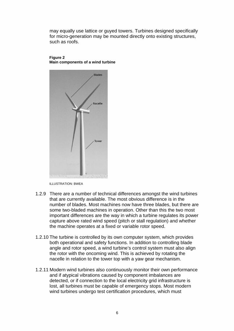
may equally use lattice or guyed towers. Turbines designed specifically for micro-generation may be mounted directly onto existing structures, such as roofs.
Figure 2 Main components of a wind turbine
ILLUSTRATION: BWEA
1.2.9 There are a number of technical differences amongst the wind turbines that are currently available. The most obvious difference is in the number of blades. Most machines now have three blades, but there are some two-bladed machines in operation. Other than this the two most important differences are the way in which a turbine regulates its power capture above rated wind speed (pitch or stall regulation) and whether the machine operates at a fixed or variable rotor speed.
1.2.10 The turbine is controlled by its own computer system, which provides
both operational and safety functions. In addition to controlling blade angle and rotor speed, a wind turbine’s control system must also align the rotor with the oncoming wind. This is achieved by rotating the nacelle in relation to the tower top with a yaw gear mechanism.
1.2.11 Modern wind turbines also continuously monitor their own performance
and if atypical vibrations caused by component imbalances are detected, or if connection to the local electricity grid infrastructure is lost, all turbines must be capable of emergency stops. Most modern wind turbines undergo test certification procedures, which must
6

conform to the guidelines laid down by the International Electro-technical Commission (IEC).
1.2.12 Wind turbines can be deployed singly, in small clusters, or in larger
groups known as wind farms. Factors that may influence the size of a development include the physical nature of the site, the capacity of the local electricity distribution network and the organisation undertaking the development. It is likely that the Region’s wind resource will be harnessed most satisfactorily using a mixture of these types of development.
1.2.13 The direction of rotation of the wind turbine rotors will be common
across a wind farm. Wind turbines are usually semi-matt white, off white or grey in colour, often as a condition of planning permission. The colours of the blades, nacelle and towers are normally the same.
Spacing of Turbines 1.2.14 Indicatively wind turbines need to be positioned so that the distances
between them are between 3-10 rotor diameters (about 180-600 metres for a wind farm using 60m diameter, 1.3MW wind turbines) depending on the individual circumstances of the site. This spacing represents a compromise between compactness, which minimises capital cost, and the need for adequate separations to lessen energy loss through wind shadowing from upstream machines. The required spacing will often be dependent on the prevailing wind direction as illustrated in Figure 3 below, which shows a possible layout for a site in Northern Ireland with a typical South Westerly prevailing wind direction.
Figure 3 Example turbine spacing in a wind farm with a South Westerly prevailing wind direction
7
1.2.15 All development associated with wind farm proposals, including the sweep from the turbine blades, will generally be expected to be contained within the boundary or the site curtilage, unless there is written agreement from adjoining landowners.
Other Infrastructure 1.2.16 In addition to wind turbines, the required infrastructure of a wind farm
consists of adequate road/site access, temporary contractors compound, borrow pits, on site-tracks, turbine foundations, crane hard standings, one or more anemometer masts, a construction compound, electrical cabling and an electrical sub-station and control building. Some of these features are permanent and others are required only in the construction phase and as such are temporary.
1.2.17 One or more anemometer masts may be required on-site. These are
usually slender structures with guy supports, built to the hub height of the turbines, with anemometers and wind vanes mounted at different heights. Permanent anemometer masts may be supported by a lattice tower. Anemometer masts are needed as part of the project planning and design process but they are also needed post-construction in order to provide control information.
1.2.18 A construction compound will generally be specified in the proposal.
While this is of a temporary nature, its location should be identified with the planning application.
1.2.19 The road access to a wind farm site will need to be able to
accommodate trailers carrying the longest loads (usually the blades), as well as the heaviest and widest loads (generally the cranes required in erection). Amendments to existing roads required to gain access to site should be detailed in any wind farm planning application.
1.2.20 On-site tracks need to meet the weight and dimensional requirements
detailed above. There will be an operational requirement for decommissioning and to gain access to the site for routine maintenance with light vehicles, as well as to reach the site with loads potentially as large as those initially used (as in the case of a major component failure).
1.2.21 Larger hard standings are also required next to each turbine to act as
bases for cranes during turbine erection and component lay down areas. These hard standing should be constructed and finished in an appropriate material so as not to adversely effect the chemical composition of the surrounding soil.
1.2.22 The towers of the turbines are fixed to a concrete foundation whose
surface will normally be flush with the surrounding ground. This foundation pad is likely to be square or hexagonal in shape and about 7-20 metres across. The diameter of the base of the turbine tower is
8
likely to be 2-5 metres. The land area actually used by the turbines is therefore very small. On land where public access is allowed, people might walk right up to the base of the towers without interfering with turbine operation. On land normally used for agricultural purposes, agricultural use could continue right up to the edge of the foundations.
Connection to the Electricity Grid 1.2.23 A wind farm is likely to be connected to the electricity distribution
network just like any other power station. Small transformers are required to change the generating voltage (likely to be 690V) to a common site voltage which is likely to be 11kV, 33kV or 110 kV. Depending on the model of turbine used, these transformers can either be housed outside or within the turbine tower. The output from the turbines in a wind farm is normally connected to a single point via underground cables.
1.2.24 Responsibility for the routing of electrical cabling onwards from the
sub-station to the nearest suitable point of the local electricity distribution network is the responsibility of the District Network Operator, presently NIE (Northern Ireland Electricity). This will be achieved either by a standard 3-wire system mounted on wooden poles or by lines laid underground. It should be noted, however, that laying high voltage cables underground is much more expensive (around 6-20 times greater) than pole-mounted overhead systems and would be likely to be used only for limited lengths and/or in special circumstances. Whilst the routing of such lines by NIE is usually dealt with separate to the planning application for the wind farm, developers will generally be expected to provide indicative details of likely routes and the anticipated method of connection (over ground or underground).
Operation and Maintenance 1.2.25 A wind farm is often equipped with a central monitoring system. This
consists of a computer that supervises the operation of the farm and can communicate with a remote headquarters. Wind farms are likely to be un-manned, and their operational status regularly checked through the central monitoring system and remote link. Such a checking system may be housed in a small building somewhere on a wind farm site or may quite normally be combined with the sub-station. Remote links will require associated equipment in order to allow communication to take place, for example an aerial or dish.
Wind Resource 1.2.26 The energy produced by a wind turbine depends on the strength of the
wind to which it is exposed. The simplest indicator of the wind resource available at a given location is the annual mean wind speed at the site (usually given at the hub height of the turbine). A machine located on a
9
site which has an annual mean wind speed of 6 metres per second will typically produce only half as much energy as the same machine on a site where the annual wind speed is 8 metres per second.
1.2.27 For any given location the wind speed rises with elevation above the
ground due to wind shear. The degree of wind shear (the rate at which the wind speed increases when moving vertically away from the ground) is dependent on the surrounding ground conditions; the higher the surrounding obstructions (e.g. vegetation or buildings) the greater the wind shear produced. Due to this, raising the hub height of the turbines, by mounting them on taller towers, can increase the energy capture at any given site. Current hub heights available to developers are between 50-125m.
1.2.28 As well as affecting the wind shear, surrounding obstacles such as
woodlands and buildings will increase the turbulence in the wind. Higher turbulence levels in the wind adversely affect wind turbine performance and life expectancy and, as such, developers will look to position turbines as far away from obstacles as is practicable. Again, the use of taller towers can ameliorate this effect by placing the rotor in less disturbed air.
1.2.29 Assessing whether a particular site will harness wind power
satisfactorily entails using historical meteorological data (available from the Meteorological Office) and information derived from anemometers placed on site. Anemometer masts are normally required on a site for at least 12 months; the longer measurements are taken the better the predictions will be. The measurements from the anemometers help to determine whether or not a candidate site is suitable and, if it is, the measurements help to determine the best position for the wind turbines within the site’s boundary. The masts should be approximately as tall as the hub height of the planned turbine. However, often when the mast is erected it is not known either if the site is suitable for wind farming or which turbine type would be most suitable. Masts are usually 25-80m tall. Planning permission is required to erect a temporary anemometer mast.
1.2.30 The mean wind speed at hub height (along with the statistical
distribution of predicted wind speeds about this mean and the wind turbines used) will determine the energy captured at a site. The simplest way of expressing the energy capture at a site is by use of the Capacity Factor.
1.2.31 This can be expressed alternatively as the actual energy generated by
a wind turbine over the course of 1 year divided by the energy that would have been generated by a wind turbine over the course of 1 year had the wind been consistently blowing at speeds between rated and cut-out (typically 12-25m/s). Capacity factors in the UK may generally fall anywhere between 0.2 and 0.5, with 0.3 being typical in the UK.
10
PLANNING ISSUES
General 1.3.1 While the Department is reviewing permitted development for small
scale renewable energy development for both domestic and non-domestic premises, all development involving wind turbines currently requires planning permission under the Planning (Northern Ireland) (Order) 1991.
1.3.2 The successful development of wind energy always entails detailed
consideration of a wide range of factors and the developer will often need to provide information on some if not all of the following matters: • Local environmental impacts including noise, shadow flicker,
electromagnetic interference, etc; • Overall economic and social benefits attributed to the scheme; • Potential impact of the project on nature conservation, to include
direct and indirect effects on protected sites, on habitats and species of ecological sensitivity and biodiversity value and, where necessary, management plans to deal with the satisfactory co-existence of the wind energy development and the particular species/habitat identified;
• Potential impact of the project on the built heritage including archaeology;
• Potential impact on ground conditions, including peat stability; • Potential impact on site drainage, sedimentation of water bodies
and other hydrological effects, such as impact on water supply and quality and watercourse crossings;
• Size, scale and layout and the degree to which the wind energy project is visible over certain areas;
• Landscape character and visual impact issues including ancillary development, such as access roads;
• Adequacy of local access road network to facilitate construction of the project and transportation of large machinery and turbine parts to site;
• Information on any cumulative effects due to other projects, including effects on natural heritage and visual effects and potential cumulative noise impact;
• Information on the location of borrow pits proposed and an indication as to the quarries to be used during the construction phase and associated remedial works thereafter;
• Temporary and/or permanent storage, disposal or elimination of waste/surplus material from construction/site clearance, particularly significant for peatland sites; and
• Decommissioning considerations. 1.3.3 Although in the past most windfarm development tended to be located
in upland areas due to higher wind speeds, technological advances, and changes to the renewable electricity markets have resulted in wind
11

speed being less pivotal in the site selection process. Generally, whether there is a reasonable prospect of obtaining planning permission is becoming a much more dominant factor in the initial site selection process.
1.3.4 The planning system exists to regulate the development and use of
land in the public interest. The material question is whether the proposal would have an unacceptable detrimental effect on the locality generally, and on amenities that ought, in the public interest, to be protected. Each planning application will be considered on its own merits, and the argument that granting permission might lead to another application will not be sufficient grounds for refusal.
Specific Issues 1.3.5 There are a number of issues specific to wind turbine developments
that need to be considered when determining an application for planning permission. Where Environmental Impact Assessment (EIA) is deemed necessary (see paragraph 1.4.4) the potential issues should be covered in the Environmental Statement but, for smaller developments that do not require a full EIA, the Department will often still require some or all of the issues to be addressed through an environmental report to accompany the planning application. The information required will depend on the individual circumstances of the case and the applicant should enter into pre-application discussions with the local divisional planning office.
Nature Conservation 1.3.6 Planning Policy Statement 2 Planning and Nature Conservation sets
out the Department’s current planning policies on nature conservation that are taken into account when considering any development of land. As the development of a wind farm is a civil engineering project, there can be potentially serious implications for biodiversity. The major ecological impacts are most likely to be associated with site infrastructure rather than the turbines themselves – other than the impact of the moving blades upon birds and bats, and the advice contained in PPS 2 should cover all aspects of the development. With such extensive application sites there should often be opportunities for developers to mitigate for any potential ecological damage and preferably enhance current wildlife habitats.
1.3.7 Beyond designated sites and peatland habitats the impact of a wind
farm on local nature conservation interests should be minimal. A typical wind farm will usually leave the land between the turbines unaffected. There is little evidence that domesticated or wild animals will be affected by a wind farm – indeed, there are examples of cows and sheep grazing right up to the base of turbines.
12

1.3.8 Applications to harness wind energy may be made in Sites of International Nature Conservation Importance, and such applications will be subject to the most rigorous examination. Developers should also note that applications which have the potential to significantly effect any such site as a matter of policy will be subject to an Appropriate Assessment1.
1.3.9 Experience indicates that bird species and their habitats are rarely
affected by wind turbine developments and the impact of an appropriately designed and located wind farm on the local bird life should, in many cases, be minimal. To date, the most common concern has been the risk of ‘bird strike’ i.e. birds flying through the area swept by the blades and being hit, causing injury or death. This is most likely to occur if a wind turbine is erected directly in a migration path, where there are high concentrations of particular species (i.e. birds feeding), or where there are vulnerable species. Most birds in flight can be expected to take action to avoid obstacles but different species will vary in their reaction and manoeuvrability. Most evidence to date suggests that the risk of collision is minimal. However, some areas are important for a variety of bird species protected under the EU and UK legislation (SPAs, SACs and ASSIs). These could represent potential constraints to wind farm development. As indicated in PPS 2 on nature conservation, the importance of complying with international and national conservation obligations must be recognised and wind farms should not adversely affect the integrity of designated sites. Protected species, such as hen harriers, occupy many areas outside designated sites and are protected across Northern Ireland. These factors have to be considered against the positioning and size of turbines, including the size of the area swept by the blades in relation to the air space used by the birds in the vicinity of the development.
1.3.10 Early consultation between the developer and the Northern Ireland
Environment Agency (NIEA) and RSPB is recommended. Most sites will require an assessment of breeding birds (between late March and early June) and wintering birds (September to March). Others, where potential ornithological sensitivities are higher, may require substantially more survey work, including studies of wintering/passage birds, raptors and moorland birds and detailed observations to quantify bird flight activity across the site.
1.3.11 Among the other potential impacts to birds, loss of habitat, the
deposition of spoil or hazardous substances from construction and operation, scrub and hedgerow removal should also be assessed.
1 Regulation 43, Conservation (Natural Habitats, etc) Regulations (Northern Ireland) 1995
13
“The risks of disturbance to bird species during construction and operation of the wind farm is also an important consideration. For some species this is of greater potential significance than collision mortality. Scottish Natural Heritage, in consultation with the British Wind Energy Association (BWEA), is preparing a ‘Methodology for assessing the effect of wind farms on ornithological interests’. Whilst this publication tackles the situation in Scotland it is equally relevant to England. In addition, the DTI’s Renewable Energy Programme has published a report ‘Cumulative effects of wind turbines’ in which Section 3 deals with ‘Cumulative effects on birds’. Both will be of use to developers when assessing the potential impact of proposed developments on bird life. Royal Society for the Protection of Birds (RSPB), World Wildlife Fund (WWF), English Nature and BWEA have also published ‘Wind Farm Development and Nature Conservation’. Another useful source of information is ‘Windfarms and Birds: An analysis of the effects of wind farms on birds, and guidance on environmental assessment criteria and site selection issues.” RHW Langston & JD Pullan (2003). BirdLife International on behalf of the Berne Convention.
1.3.12 The impact of the moving blades of a wind turbine upon bats and their
ultrasound has also on occasion been raised as a concern, but there is little evidence to date to suggest that significant numbers of deaths or injuries will occur. Early consultation between the developer and NIEA and the Bat Conservation Trust is recommended. Some sites may require the submission of a bat survey to assess the use of the site.
1.3.13 In addition, under the EC Habitats Directive, other species or habitats
of special interest may be present. For example, active peatland is of particular importance to the Region for its biodiversity, water and carbon storage and can be adversely affected by wind farm development. In general such areas should be avoided and where possible, encourage the restoration of degraded areas.
1.3.14 The main potential impacts on habitats that can result in the reduction,
or loss, of biodiversity are: • Direct loss of habitat to the developments’ infrastructure, including
turbine foundations, crane pads, buildings, roads, quarries and borrow pits;
• Degradation of habitats through alteration or disturbance, in particular arising from changes to hydrology that may alter the surface or groundwater flows and levels, and drainage patterns critical in peatlands and river headwaters and increase the risk of bog burst;
• Fragmentation of habitats and increased edge effects; • Changes to land management brought about by improved access;
and
14
• Degradation and loss of habitats outside the development site, especially wetland habitats that may arise from pollution, siltation and erosion originating from within the development site.
1.3.15 Developers should ensure that their ecological advisers enter into early
discussions with NIEA about the presence and importance of species and habitats in and around a proposed development site. Discussions should assess any potential impacts and the scope for mitigation in the design and layout. A Habitat Survey could usefully inform these discussions. In addition discussions with locally based groups such as the Ulster Wildlife Trust or RSPB could benefit the ecological assessment procedure.
Landscape and Visual Impact 1.3.16 In order to minimise wind speed variations, commercial wind energy
developments need to be located in areas of relatively smooth and rounded relief. They also require ready access to the electricity transmission and distribution system unless they are intended solely for private use. The current generation of turbines is capable of operating at lower wind speeds than previously due to the marketing regime and wind turbine size increases, which has the effect of increasing the types of areas (and landscapes) that may attract developer interest.
1.3.17 There are a number of publications that can assist planners,
developers and other professionals in addressing landscape issues. These include the Landscape Institute publication Guidelines for Landscape and Visual Impact Assessment 2nd edition, 2002 (currently under review); Scottish Natural Heritage (2001) Guidelines on the Environmental Impacts of Windfarms and Small Scale Hydroelectric Schemes; and Scottish Natural Heritage (2005) Guidance: Cumulative Effect of Windfarms, Version 2.
1.3.18 Northern Ireland has a variety of landscapes as identified in the
Northern Ireland Landscape Character Assessment, 2000. Some will be able to accommodate wind farms more easily than others, on account of their landform and relief and ability to limit visibility. Some are highly valued for their quality. There are no landscapes into which a wind farm will not introduce a new and distinctive feature. Given the Government’s commitment to addressing the important issue of climate change and the contribution expected from renewable energy developments, particularly wind farms, it is important for society at large to accept them as a feature of many areas of the Region for the foreseeable future.
1.3.19 This is not to suggest that areas valued for their particular landscape
and/or nature conservation interest will have to be sacrificed. Nor that elsewhere, attempts to lessen the impacts by integrating the development into the surrounding landscape would not be worthwhile. On the contrary, it emphasises the need for account to be taken of
15

regional and local landscape considerations. Careful consideration is required to locate the development and even though highly visible, every effort should be made to reduce the impact and aid integration into the local landscape.
1.3.20 The landscape and visual impact of wind turbines is influenced by:
• land form; • landscape character and features; • number, size and layout of turbines, and their inter-relationship; • how the turbines relate to the skyline • design and colour; • visual receptors; • access tracks; and • ancillary components like power lines and substations.
In addition it is acknowledged that the construction and transportation of turbines will have an impact on the local landscape.
1.3.21 The capacity of the landscape to accommodate wind farm development
depends on three considerations: • the degree of impact the development will have on the existing
character of the landscape; • the sensitivity of the character of the landscape; and • the extent to which this impact can be modified and reduced by
design. However it will not necessarily be the case that the extent of visual impact or visibility of wind farm development will give rise to negative effects; wind farm developments are by their nature highly visible yet this in itself should not preclude them as acceptable features in the landscape.
1.3.22 The ability of the landscape to absorb development depends on careful
siting, the skill of the designer, and the inherent characteristics of the landscape such as landform, ridges, hills, valleys, and vegetation.
1.3.23 A cautious approach is necessary in relation to those landscapes which
are of designated significant value, such as Areas of Outstanding Natural Beauty, and the Giant’s Causeway World Heritage Site, and their wider settings. Here, it may be difficult to accommodate wind turbines without detriment to the Region’s cultural and natural heritage assets.
1.3.24 The document ‘Wind Energy Development in Northern Ireland’s
Landscapes’, published by the Northern Ireland Environment Agency identifies landscape characteristics that may be sensitive to wind turbine development. This document provides supplementary planning guidance on the landscape and visual analysis process, and the indicative type of development that may be appropriate. While the SPG will be taken into account in assessing all wind turbine proposals it is not intended to be prescriptive.
16
Visual Impact 1.3.25 Turbines in wind farms will normally be tall, frequently located in open
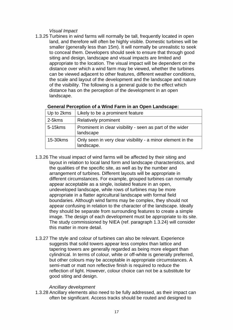
land, and therefore will often be highly visible. Domestic turbines will be smaller (generally less than 15m). It will normally be unrealistic to seek to conceal them. Developers should seek to ensure that through good siting and design, landscape and visual impacts are limited and appropriate to the location. The visual impact will be dependent on the distance over which a wind farm may be viewed, whether the turbines can be viewed adjacent to other features, different weather conditions, the scale and layout of the development and the landscape and nature of the visibility. The following is a general guide to the effect which distance has on the perception of the development in an open landscape.
General Perception of a Wind Farm in an Open Landscape: Up to 2kms Likely to be a prominent feature 2-5kms Relatively prominent 5-15kms Prominent in clear visibility - seen as part of the wider
landscape 15-30kms Only seen in very clear visibility - a minor element in the
landscape. 1.3.26 The visual impact of wind farms will be affected by their siting and
layout in relation to local land form and landscape characteristics, and the qualities of the specific site, as well as by the number and arrangement of turbines. Different layouts will be appropriate in different circumstances. For example, grouped turbines can normally appear acceptable as a single, isolated feature in an open, undeveloped landscape, while rows of turbines may be more appropriate in a flatter agricultural landscape with formal field boundaries. Although wind farms may be complex, they should not appear confusing in relation to the character of the landscape. Ideally they should be separate from surrounding features to create a simple image. The design of each development must be appropriate to its site. The study commissioned by NIEA (ref. paragraph 1.3.24) will consider this matter in more detail.
1.3.27 The style and colour of turbines can also be relevant. Experience
suggests that solid towers appear less complex than lattice and tapering towers are generally regarded as being more elegant than cylindrical. In terms of colour, white or off-white is generally preferred, but other colours may be acceptable in appropriate circumstances. A semi-matt or matt non reflective finish is required to reduce the reflection of light. However, colour choice can not be a substitute for good siting and design. Ancillary development
1.3.28 Ancillary elements also need to be fully addressed, as their impact can often be significant. Access tracks should be routed and designed to
17

minimise both visual and habitat impacts. This can be minimised by careful route selection, which takes account of layout and appropriate surfacing material together with the impact of cuttings, embankments and drainage channels. Managing problems of erosion and providing for reinstatement of vegetation along the track is essential. Fencing, buildings and anemometer masts should be located and designed in a way which minimises clutter. It should be noted that peat is very slow at reinstatement and may require active management, e.g. brashings from nearby habitat, to limit the visual impact and erosion potential. The location and extent of the use of any borrow pit should also be indicated in the visual assessment.
1.3.29 The impact of the transportation of components to site on the minor
road network and on the associated trees and hedges should be assessed e.g. transportation may involve lorries up to 45 metres in length requiring large turning circles.
1.3.30 Power lines connecting the individual turbines to the on-site substation
will be underground. To avoid visual confusion, routing and design of power lines, connecting the wind farm substation to the electricity distribution system, will require sensitive treatment.
Visual Assessment
1.3.31 There are a number of techniques which may be used to inform visual assessment of a proposed development: • a zone of theoretical visibility map will show where a wind farm
may be seen from; • viewpoint analysis based on key viewpoints throughout the
surrounding area; • computer generated wireline diagrams will indicate how wind
turbines will appear from specific viewpoints; and • photo- and video montages are images whereby an impression
of a proposed development is superimposed upon an actual photograph or video of the proposed site.
All of these have strengths and limitations.
1.3.32 In comparison with other, well-established, forms of development in the
countryside, wind turbines are relatively unfamiliar, prominently vertical and have the significant characteristic of movement. Individually or in groups, they will be distinctive features in the landscape. The visual impact of wind turbines must be assessed with these characteristics clearly in mind. Cumulative Landscape and Visual Impacts
1.3.33 The cumulative impact of a number of neighbouring developments is an important material consideration. The nature and character of the location, and the landscape in which a development is located, will in part determine the acceptability or otherwise of siting proposals in proximity to each other.
18
1.3.34 A number of factors have influenced the current geographic distribution
of wind farm proposals in Northern Ireland, for example: • the distribution of the viable wind resource; • technical and economic constraints to the viability of exploiting
different wind speeds; • electricity grid access constraints; • protected areas; and • planning policy.
1.3.35 These have tended to focus developments in a relatively limited
number of areas. With increasing numbers of existing and proposed wind energy developments it is necessary to address the cumulative impacts on the landscape with reference to the context that probability of cumulative impacts is increased by existing renewable energy targets and hence greater demand for wind energy developments.
1.3.36 The cumulative effects of wind farm development can arise as the
combined consequences of: • an existing wind energy development and a proposed extension
to that development; • proposals for more than one wind energy development within an
area; • proposal(s) for new wind energy development(s) in an area with
one or more existing development(s); and • any combination of the above.
1.3.37 In assessing cumulative effects, it is unreasonable to expect these to
extend beyond schemes in the vicinity that have been built, those which have permissions and those that are currently the subject of undetermined applications.
Ground Water Conditions/Geology 1.3.38 In assessing wind energy developments, the underlying geology is an
important factor. Information on the following issues should be submitted as part of a planning application to enable adequate assessment of the impact of the proposed wind energy development and any mitigating measures proposed to counter the impacts: • A geological assessment of the locality; • A geotechnical assessment of the overburden and bedrock; • A landslide and slope stability risk assessment for the site for all
stages of the project, with proposed mitigation measures where appropriate (this should also consider the possible effects of storage of excavated material);
• An assessment of whether the development could create a bog burst or landslide hazard;
• Location of the site in relation to any area or site that has been identified as an important geological site or area and the potential impacts of the proposal on the geological resource.
19

• Location of the site in relation to areas of significant mineral or aggregate potential;
• An assessment of any potential impacts of the development on groundwater; and
• Details of any borrow-pits proposed on site should be shown on the planning application and details given where blasting is proposed, such as on the avoidance and remediation of land slippage (if so are there any impacts discussed or mitigation methods proposed).
1.3.39 In order to ensure that the above issues have been fully addressed, a
developer should consult with the Geological Survey of Northern Ireland and obtain professional advice/source reports from suitably qualified geotechnical engineers, engineering geologists or geologists as appropriate. If upland sites are proposed, the application should be accompanied by a statement from a geologist, a hydro-geologist or an engineer with expertise in soil mechanics.
Archaeology and the Built Heritage 1.3.40 Planning Policy Statement 6 Planning, Archaeology and the Built
Heritage sets out planning policy for the protection and conservation of archaeological remains and features of the built heritage.
1.3.41 The potential impact of the proposed wind energy development on the
archaeological heritage of the site should be assessed. The assessment should address direct impacts on the integrity, visual amenity, and setting of individual sites and monuments or any location designated as an Area of Significant Archaeological Interest. It should also detail appropriate mitigation measures, such as through a desktop study and a field inspection where necessary.
1.3.42 In addition, an assessment should be made on the potential impact of
the proposed wind energy development on the wider built heritage of the locality and its landscape context, where relevant. This is particularly necessary in the case of structures impacting on Listed Buildings; Historic Parks, Gardens and Demesnes; Conservation Areas; and Areas of Townscape Character.
Noise 1.3.43 Well designed wind farms should be located so that increases in
ambient noise levels around noise-sensitive developments are kept to acceptable levels with relation to existing background noise. This will normally be achieved through good design of the turbines and through allowing sufficient distance between the turbines and any existing noise-sensitive development so that noise from the turbines will not normally be significant. As a matter of best practice for wind farm development, the Department will generally apply a separation distance of 10 times rotor diameter to occupied property (with a minimum distance of not less than 500m). In applying this separation
20
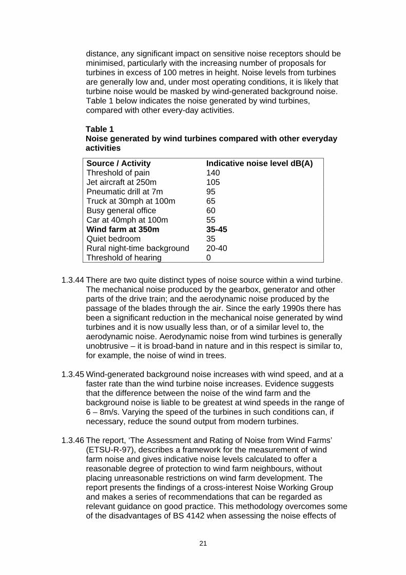
distance, any significant impact on sensitive noise receptors should be minimised, particularly with the increasing number of proposals for turbines in excess of 100 metres in height. Noise levels from turbines are generally low and, under most operating conditions, it is likely that turbine noise would be masked by wind-generated background noise. Table 1 below indicates the noise generated by wind turbines, compared with other every-day activities.
Table 1 Noise generated by wind turbines compared with other everyday activities
Source / Activity Indicative noise level dB(A) Threshold of pain 140 Jet aircraft at 250m 105 Pneumatic drill at 7m 95 Truck at 30mph at 100m 65 Busy general office 60 Car at 40mph at 100m 55 Wind farm at 350m 35-45 Quiet bedroom 35 Rural night-time background 20-40 Threshold of hearing 0
1.3.44 There are two quite distinct types of noise source within a wind turbine.
The mechanical noise produced by the gearbox, generator and other parts of the drive train; and the aerodynamic noise produced by the passage of the blades through the air. Since the early 1990s there has been a significant reduction in the mechanical noise generated by wind turbines and it is now usually less than, or of a similar level to, the aerodynamic noise. Aerodynamic noise from wind turbines is generally unobtrusive – it is broad-band in nature and in this respect is similar to, for example, the noise of wind in trees.
1.3.45 Wind-generated background noise increases with wind speed, and at a
faster rate than the wind turbine noise increases. Evidence suggests that the difference between the noise of the wind farm and the background noise is liable to be greatest at wind speeds in the range of 6 – 8m/s. Varying the speed of the turbines in such conditions can, if necessary, reduce the sound output from modern turbines.
1.3.46 The report, ‘The Assessment and Rating of Noise from Wind Farms’
(ETSU-R-97), describes a framework for the measurement of wind farm noise and gives indicative noise levels calculated to offer a reasonable degree of protection to wind farm neighbours, without placing unreasonable restrictions on wind farm development. The report presents the findings of a cross-interest Noise Working Group and makes a series of recommendations that can be regarded as relevant guidance on good practice. This methodology overcomes some of the disadvantages of BS 4142 when assessing the noise effects of
21

windfarms, and should be used in the assessment and rating noise from wind energy developments.
22

Recommended Good Practice on Controlling Noise from Wind Turbines From ‘The Assessment and Rating of Noise from Wind Farms’ (ETSU for DTI 1997). The current practice on controlling wind farm noise by the application of noise limits at the nearest noise-sensitive properties is the most appropriate approach. Noise limits should be applied to external locations and should apply only to those areas frequently used for relaxation or activities for which a quiet environment is highly desirable. Noise limits set relative to the background noise are more appropriate in the majority of cases. Generally, the noise limits should be set relative to the existing background noise at the nearest noise-sensitive properties and the limits should reflect the variation in both turbine source noise and background noise with wind speed. It is not necessary to use a margin above background noise levels in particularly quiet areas. This would unduly restrict developments that are recognised as having wider national and global benefits. Such low limits are, in any event, not necessary in order to offer a reasonable degree of protection to wind farm neighbours. Separate noise limits should apply for day-time and for night-time as during the night the protection of external amenity becomes less important and the emphasis should be on preventing sleep disturbance. Absolute noise limits and margins above background should relate to the cumulative effect of all wind turbines in the area contributing to the noise received at the properties in question. Any existing turbines should not be considered as part of the prevailing background noise. Noise from the wind farm should be limited to 5 dB(A) above background for both day- and night-time, remembering that the background level of each period may be different. The LA90,10min descriptor should be used for both the background noise and the wind farm noise, and when setting limits it should be borne in mind that the LA90,10min of the wind farm is likely to be about 1.5-2.5 dB(A) less than the LAeq measured over the same period. The use of the LA90,10min descriptor for wind farm noise allows reliable measurements to be made without corruption from relatively loud, transitory noise events from other sources. A fixed limit of 43 dB(A) is recommended for night-time. This is based on a sleep disturbance criteria of 35 dB(A) with an allowance of 10 dB(A) for attenuation through an open window (free field to internal) and 2 dB(A) subtracted to account for the use of LA90,10min rather than LAeq,10min. Both day- and night-time lower fixed limits can be increased to 45 dB(A) to increase the permissible margin above background where the occupier of the property has some financial interest in the wind farm. In low noise environments the day-time level of the LA90,10min of the wind farm noise should be limited to an absolute level within the range of 35-40 dB(A). The actual value chosen within this range should depend upon: the number of dwellings in the neighbourhood of the wind farm, the effect of noise limits on the number of kWh generated, and the duration of the level of exposure. For single turbines or wind farms with very large separation distances between the turbines and the nearest properties, a simplified noise condition may be suitable. If the noise is limited to a LA90,10min of 35 dB(A) up to wind speeds of 10 m/s at 10 m height, then this condition alone would offer sufficient protection of amenity, and background noise surveys would be unnecessary.
23
Low Frequency Noise (Infrasound) 1.3.47 There is no evidence that ground transmitted low frequency noise from
wind turbines is at a sufficient level to be harmful to human health. A comprehensive study of vibration measurements in the vicinity of a modern wind farm was undertaken in the UK in 1997 by ETSU for the DTI (ETSU W/13/00392/REP). Measurements were made on site and up to 1km away – in a wide range of wind speeds and direction.
1.3.48 The study found that:
• Vibration levels 100m from the nearest turbine were a factor of 10 less than those recommended for human exposure in critical buildings (i.e. laboratories for precision measurement); and
• Tones above 3.0 Hz were found to attenuate rapidly with distance – the higher frequencies attenuating at a progressively increasing rate.
1.3.49 In a subsequent study by DTI entitled “The measurement of low
frequency noise at three UK Wind Farms, W/45/00656/00/00” the principal findings were that infrasound associated with modern wind turbines is not a source which will result in noise levels which may be injurious to the health of a wind farm neighbour. In addition from the data collected, internal noise levels were deemed insufficient to wake up residents at the three sites investigated.
Safety 1.3.50 Experience indicates that properly designed and maintained wind
turbines are a safe technology. The very few accidents that have occurred involving injury to humans have been caused by failure to observe manufacturers’ and operators’ instructions for the operation of the machines. There has been no example of injury to a member of the public.
1.3.51 The only source of possible danger to human or animal life from a wind
turbine would be the loss of a piece of the blade or, in most exceptional circumstances, of the whole blade. Many blades are composite structures with no bolts or other separate components. Blade failure is therefore most unlikely. Even for blades with separate control surfaces on or comprising the tips of the blade, separation is most unlikely.
1.3.52 For wind farm developments the best practice separation distance of
10 times rotor diameter to occupied property should comfortably satisfy safety requirements. For a smaller individual wind turbine, for example on a farm enterprise, the fall over distance (i.e. the height of the turbine to the tip of the blade) plus 10% is often used as a safe separation distance.
24
Proximity to Road and Railways 1.3.53 Applicants are advised to consult at an early stage with DRD Roads
Service for development affecting public roads. In the case of railway lines consultation should take place with Translink.
1.3.54 Although wind turbines erected in accordance with best engineering
practice are considered to be stable structures, they should be set-back at least fall over distance plus 10% from the edge of any public road, public right of way or railway line so as to achieve maximum safety.
1.3.55 Concern is often expressed over the effects of wind turbines on car
drivers, who may be distracted by the turbines and the movement of the blades. Drivers are faced with a number of varied and competing distractions during any normal journey, including advertising hoardings, which are deliberately designed to attract attention. At all times drivers are required to take reasonable care to ensure their own and others’ safety. Wind turbines should therefore not be treated any differently from other distractions a driver must face and should not be considered particularly hazardous. The provision of appropriately sited lay-bys for viewing purposes may be helpful in giving an opportunity to view the wind energy development in safety; lay-by size should be adequate to cater for tour buses.
Proximity to Power Lines 1.3.56 Wind turbines should be separated from overhead power lines in
accordance with the Energy Networks Association standard TS 43-8 issue 3 ‘Overhead Line Clearances’.
Lightning Strike 1.3.57 The possibility of attracting lightning strikes applies to all tall structures
and wind turbines are no different. Appropriate lightning protection measures are incorporated in wind turbines to ensure that lightning is conducted harmlessly past the sensitive parts of the nacelle and down into the earth.
Electromagnetic Production and Interference 1.3.58 Wind turbines contain electrical machines producing power and as a
consequence electromagnetic emissions. These however are at a very low level comparable to most domestic appliances.
1.3.59 Provided careful attention is paid to siting, wind turbines should not
cause any significant adverse effects on communication systems which use electromagnetic waves as the transmission medium (e.g. television, radio, telecommunication links, and police and emergency service links). Generally, turbine siting can mitigate any potential impacts, as the separation distance required to avoid problems is
25

generally a matter of a few hundred metres. In some cases, it may be possible to effectively re-route the signal around the development, at the developer’s expense, to overcome the problem.
1.3.60 Scattering of signal mainly affects domestic TV and radio reception,
and the general public may be concerned that a wind farm will interfere with these services. Experience has shown that when this occurs it is of a predictable nature and can generally be alleviated by a range of measures such as aerial redirection/upgrade or the installation or modification of a local repeater station or cable connection.
1.3.61 Specialist organisations responsible for the operation of the
electromagnetic links typically require a 100m clearance either side of a line of sight link from the swept area of turbine blades although some operators are willing to accept Fresnel zones2 of avoidance. There may however be additional constraints in relation to the police TETRA system. Individual consultations would be necessary to identify each organisation’s safeguarding distance. Effects on such links can usually be resolved through careful siting of individual turbines
1.3.62 Since a large number of bodies use communication systems, and
some of the users are commercially sensitive or of strategic importance, it is often difficult to obtain a definitive picture of all the transmission routes across a potential site. The Office of Communications (OFCOM) holds a central register of all civil radio communications operators in the UK and acts as a central point of contact for identifying specific consultees relevant to a site. OFCOM will identify any radio installations relevant to a wind farm site. Although OFCOM passes any enquiry on to other interested parties, who should respond to an application, this process is only partial and an applicant seeking planning permission would be well advised to make direct contact with any authorities/bodies which are likely to be interested – a list of potentially interested parties is given at the end of this Section.
1.3.63 It may also be necessary to consult utility providers and the emergency
services such as the ambulance service and the coastguard. In particular the Police Service for Northern Ireland would encourage wind farm developers to consult them on all applications in order that the impact of their proposal on the TETRA broadcast facilities can be properly considered.
1.3.64 For proposals within 20km of the Republic of Ireland it is recommended
that developers consult with licensed operators there. A list of these operators is available on the ComReg website at www.comreg.ie. In such cases it is also advisable to contact Irish mobile phone operators.
2 The area around the visual line-of-sight that radio waves spread out into after they leave the antenna.
26

Aviation Interests 1.3.65 Wind turbines may have an adverse effect on two aspects of air traffic
movement and safety. Firstly, they may represent a risk of collision with low flying aircraft, and secondly, they may interfere with the proper operation of radar by limiting the capacity to handle air traffic, and aircraft instrument landing systems.
Risk of Collision
1.3.66 Risk of collision is likely to occur close to civilian and military airfields, and in military low flying zones. As appropriate, the Department consults with the relevant licensed operators of civil airports/airfields, the Ministry of Defence (MOD) and the National Air Traffic Service (NATS) on all proposals for wind turbine developments in Northern Ireland. The Civil Aviation Authority (CAA) can inform the applicant of any civilian airfields that are likely to be affected, but it is the responsibility of the applicant to consult the airfield management at the airfield in question. It is recommended that such consultation should occur prior to submission of an application and the applicant should take account of the airfield management’s requirements, which will depend on local topography and the preferred flight paths at the site.
1.3.67 In the interests of aviation safety, lights may be required on wind
turbine development and is mandatory in all cases where the structure exceeds 150m high. In addition, structures over 91.4m (300ft) are required to be charted on aviation maps. Developers will be required to provide details of the development to the Defence Geographic Centre.
1.3.68 There is currently no low flying training undertaken by the MOD in
Northern Ireland.
Radar 1.3.69 Any large structure is liable to show up on radar, but wind turbines can
present a particular problem as they can be interpreted by radar as a moving object, which is only intermittently seen (as the nacelle rotates to face the wind). There is a consultation zone and an advisory zone around every civilian and military air traffic radar but objections may sometimes be raised in respect of developments further afield. Consultation by the developer will also be required in respect of any meteorological radar. Developers therefore need to carefully consider this matter. Both the Irish Wind Energy Association and the British Wind Energy Association web sites give details of how adequate consultation can be achieved. In addition, developers may be required to contact the Irish Aviation Authority at the pre-planning stage with details of locations and proposed heights of turbines, to ensure that the proposed development will not cause difficulties with air navigation safety in the Republic of Ireland.
1.3.70 Because topography, intervening buildings and even tree cover can
mitigate the effect of wind turbines on radar, it does not necessarily follow that the presence of a wind turbine in a safeguarding zone will
27
have a negative effect. However, if an objection is raised by either a civil aviation or Defence Estates consultee, the onus is on the applicant to prove that the proposal will have no adverse effect on aviation interests.
1.3.71 The CAA publishes guidance to provide assistance to aviation
stakeholders when addressing wind energy related issues.
Shadow Flicker and Reflected Light 1.3.72 Under certain combinations of geographical position and time of day,
the sun may pass behind the rotors of a wind turbine and cast a shadow over neighbouring properties. When the blades rotate, the shadow flicks on and off; the effect is known as ‘shadow flicker’. It only occurs inside buildings where the flicker appears through a narrow window opening. A single window in a single building is likely to be affected for a few minutes at certain times of the day during short periods of the year. The likelihood of this occurring and the duration of such an effect depends upon: • the direction of the residence relative to the turbine(s); • the distance from the turbine(s); • the turbine hub-height and rotor diameter; • the time of year; • the proportion of day-light hours in which the turbines operate; • the frequency of bright sunshine and cloudless skies (particularly at
low elevations above the horizon); and, • the prevailing wind direction.
1.3.73 Shadow flicker generally only occurs in relative proximity to sites and
has only been recorded occasionally at one site in the UK. Only properties within 130 degrees either side of north, relative to the turbines can be affected at these latitudes in the UK – turbines do not cast long shadows on their southern side.
1.3.74 The further the observer is from the turbine the less pronounced the
effect will be. There are several reasons for this:
• there are fewer times when the sun is low enough to cast a long shadow;
• when the sun is low it is more likely to be obscured by either cloud on the horizon or intervening buildings and vegetation; and,
• the centre of the rotor’s shadow passes more quickly over the land reducing the duration of the effect.
1.3.75 At distance, the blades do not cover the sun but only partly mask it,
substantially weakening the shadow. This effect occurs first with the shadow from the blade tip, the tips being thinner in section than the rest of the blade. The shadows from the tips extend the furthest and so only a very weak effect is observed at distance from the turbines.
28

1.3.76 Problems caused by shadow flicker are rare. At distances greater than 10 rotor diameters from a turbine, the potential for shadow flicker is very low. The seasonal duration of this effect can be calculated from the geometry of the machine and the latitude of the site. Where shadow flicker could be a problem, developers should provide calculations to quantify the effect and where appropriate take measures to prevent or ameliorate the potential effect, such as by turning off a particular turbine at certain times.
1.3.77 Careful site selection, design and planning, and good use of relevant
software, can help avoid the possibility of shadow flicker in the first instance. It is recommended that shadow flicker at neighbouring offices and dwellings within 500m should not exceed 30 hours per year or 30 minutes per day3.
1.3.78 Turbines can also cause flashes of reflected light, which can be visible
for some distance. It is possible to ameliorate the flashing but it is not possible to eliminate it. Careful choice of blade colour and surface finish can help reduce the effect. Light grey semi-matt finishes are often used for this. Other colours and patterns can also be used to reduce the effect further. (See ‘The Influence of Colour on the Aesthetics of Wind Turbine Generators’ – ETSU W/14/00533/00/00).
Ice Throw 1.3.79 The build-up of ice on turbine blades is unlikely to present problems on
the majority of sites in Northern Ireland. Even where icing does occur the turbines’ own vibration sensors are likely to detect the imbalance and inhibit the operation of the machines.
Recreation and Tourism 1.3.80 In many areas in Northern Ireland, recreation and tourism are a
significant element of the local economy and can depend to varying degrees on the quality of the environment. It is not considered that wind energy developments are necessarily incompatible with tourism and leisure interests, but it is acknowledged that care does need to be taken to ensure that insensitively sited wind energy developments do not impact negatively on tourism potential. The results of survey work conducted in 2003 in the Republic of Ireland indicate that tourism and wind energy can co-exist happily4.
3 The shadow flicker recommendations are based on research by Predac, a European Union sponsored organisation promoting best practice in energy use and supply which draws on experience from Belgium, Denmark, France, the Netherlands and Germany. 4 Attitudes Towards the Development of Wind Farms in Ireland – Sustainable Energy Ireland, 2003
29
1.3.81 For future wind farms, the judgment of acceptability based on landscape protection should provide adequate protection for tourism interests. The threshold of landscape protection is generally more sensitive to wind farm development than tourism, therefore if there is deemed to be acceptable within the landscape at the planning stage, there should be no unreasonable impacts on tourism interests.
1.3.82 The educational potential of wind energy developments should also be
considered. For example, there may be scope for an interpretive centre on alternative energy resources to be located at accessible location in proximity to a wind energy development. It would be helpful if established long distance walking routes/amenity rights-of-way were identified and mapped to enable an assessment both of the extent to which recreational pursuits can be accommodated and facilitated either within or adjacent to wind energy developments. Local councils would be a useful contact point to provide information on this matter.
Construction and Operational Disturbance 1.3.83 The degree of disturbance caused by the construction phase of a wind
farm will depend on the number of turbines and the length of the construction period. Public perception of the construction phase will derive mainly from physical impact and traffic movements. The traffic movements to be expected will involve: • vehicles bringing aggregate to the site including concrete for
foundations; • vehicles removing spoil from the site; • vehicles (which may be articulated) bringing turbine components to
the site; • the vehicles of those working on the site; and, • the crane(s) to erect the turbines.
1.3.84 Although construction traffic for a wind turbine development will
essentially be no different from other developments, many turbines will be sited in areas served by the minor road network. In such cases, it may be necessary to impose suitable conditions on consents or enter a legal agreement with the developer to control the number of vehicle movements to and from the site in a specified period and, where possible, the route of such movements, particularly by heavy vehicles. Further requirements for strengthening bridges may also be required by the DRD Roads Service. Where culverting of any watercourse under site roads is planned, the provisions of Planning Policy Statement 15 Planning and Flood Risk will be taken into account. Consent from the Department of Agriculture and Rural Development’s Rivers Agency will also be required.
1.3.85 Once turbines are in operation, traffic movements to and from the site
will be very light, probably averaging two visits a week by a light commercial vehicle or car. The need to replace machine components
30
will generate heavier commercial vehicle movements, but these are likely to be infrequent. Decommissioning and Reinstatement
1.3.86 The decommissioning of a wind energy development once electricity ceases to be generated will need to be assessed. Plans for decommissioning should be outlined at the planning application stage. Issues to be addressed include restorative measures, the removal of above ground structures and equipment, landscaping and/or reseeding roads. On occasion it may be appropriate to allow tracks to remain, e.g., as part of a walking route after decommissioning.
1.3.87 A decommissioning plan may be covered in conditions and/or a legal
agreement accompanying planning permission and will be triggered by the expiry of the consent or in the event of the project ceasing to operate for a specified period. Developers should demonstrate that funding to implement decommissioning will be available when required.
1.3.88 It is likely that the duration of the planning permission will be linked to
the expected operational life of the turbines. However during this period, proposals may be forthcoming to extend the life of the project by re-equipping or to replace the original turbines with new ones. While there are obvious advantages in utilising established sites, such cases will have to be determined on their individual merit and in the light of the then prevailing policy and other relevant considerations.
INFORMATION TO ACCOMPANY A PLANNING APPLICATION
1.4.1 The developer should submit the following to accompany a wind energy application: • 7 copies of the P1 Planning Application form, accurately
completed, signed and dated; • planning fee (currently £200 per 0.1ha or part thereof of the
footprint of the development up to a maximum of £10,000); • 7 copies of the site location map with site boundary, including the
access road and land for any junction improvement outlined in red; • 7 copies of the site layout including access roads within the site,
detailed plans to scale including turbines, details of bases, access roads, wind monitoring masts, sub-stations and other ancillary development. Details of finishing materials (e.g. on turbines, sub-stations, control rooms, fences and other structures), landscaping etc. are required. Information will also be required detailing spoil storage and the location of road/site access, temporary contractors compound, borrow pits, on site-tracks, turbine foundations, crane hard standings, one or more anemometer masts, construction compound, electrical cabling and an electrical sub-station and control building of any construction.
31
1.4.2 Where wind energy proposals are deemed as EIA developments, the developer is also required to submit sufficient copies of the EIA statement to enable the Department to carry out consultations. The developer should contact the Department to ascertain the numbers of statements required and the format preferred.
1.4.3 For smaller developments that do not require a full EIA, the
Department will often still require some or all of the issues set out in paragraph 1.3.2 to be addressed through an environmental report to accompany the planning application to include for example a report detailing noise emissions and an assessment of the impact.
Environmental Impact Assessment 1.4.4 Wind turbines fall within descriptions of development listed under
Schedule 2, category 3(j) to the EIA Regulations. The Department of the Environment is required to screen applications for the need for EIA where the development involves the installation of more than 2 turbines or the hub height of any turbine or height of any other structure exceeds 15 metres
OTHER AUTHORISATIONS/CONSENTS
Grid Connection 1.5.1 Where the works required to connect the wind farm to the local
electricity distribution network are not permitted under the General Development Order it will be necessary to submit a separate planning application5. Either NIE or the wind farm developer may make such an application. Developers should provide information on the most likely route and method for the grid connection (overground or underground) to the wind farm with their planning application and as part of any EIA. The connection of the wind farm to the electricity grid forms an intrinsic part of the project. Whilst the routing of such lines by NIE is usually dealt with separate to the planning application for the wind farm, developers will generally be expected to provide indicative details of likely routes and the anticipated method of connection (over ground or underground).
1.6 In addition DETI consent for electricity generation over 10MW will be
required.
5 Please note responsibility for determining consent and granting deemed planning permission for the installation of overhead lines which have a nominal voltage of over 20 kilovolts associated with wind farms is planned to transfer to the Department of Enterprise Trade and Investment.
32
CONSULTEES 1.6.1 Wind energy developers may wish to refer to the Department’s
consultees:
• Arqiva - Crawley Court, Winchester, Hampshire, SO21 2QA • Belfast International Airport - Belfast BT29 4AB • Chief Executive, Local Government Authority • City of Derry Airport - Airport Road, Eglington BT47 3GY • Council for Nature Conservation and the Countryside - 5-33
Hill Street, Belfast, BT1 2LR • Crown Castle UK - National Grid Wireless, Wireless House,
Warwick Tech. Park, Heathcote Lane, Warwick CV34 6DD • Defence Estates Organisation - Saferguarding Bylaws,
Blakemore Drive, Sutton Coldfield, West Midlands, B75 7RL • Department of Agriculture and Rural Development –
Countryside Management Branch, Agri-Environment Schemes Management Branch, Lindesay Hall, Loughry Campus, Cookstown, BT80 9AA
• Department of Culture Arts & Leisure - Dept of Culture Arts & Leisure, Inland Fisheries Branch, Interpoint, 20-24 York Street, Belfast, BT15 1AQ
• Department of Enterprise, Trade and Investment - Energy Branch, Netherleigh, Massey Avenue, Belfast
• Department of the Environment, Heritage and Local Government –Custom House, Dublin 1, Ireland
• Enniskillen (St. Angelo) Airport - Trory, Enniskillen BT94 2FP • Environmental Health Officers, Local District Council • Fisheries Conservancy Board for Northern Ireland - HQ
Office, 1 Mahon Road, Portadown, BT62 6EE • Geological Survey (NI) – Colby House, Stranmillis Court,
Stranmillis Road, Belfast BT9 5BF • George Best Belfast City Airport - Belfast BT3 9JGH • Health & Safety Inspectorate - 83 Ladas Drive, Belfast,
BT6 9FR • Loughs Agency - 22 Victoria Road, Londonderry BT47 2AD • National Air Traffic Service - Navigation, Spectrum &
Surveillance, Spectrum House, Gatwick, West Sussex, RH6 0LG • Newtownards Airport - Ulster Flying, Portaferry Road,
Newtownards BT23 8SG • Northern Ireland Electricity – Enniskillen Business Centre,
Lacckaghboy, Tempo Road, Enniskillen, BT74 4RL • Northern Ireland Environment Agency - Natural Heritage,
Klondyke Building, Cromac Avenue, Gasworks Business Park, Lower Ormeau Road, Belfast BT7 2JA
• Northern Ireland Environment Agency – Protecting Historic Buildings, Klondyke Building, Cromac Avenue, Gasworks Business Park, Lower Ormeau Road, Belfast BT7 2JA
• Northern Ireland Environment Agency – Protecting Historic Monuments, 5-33 Hill Street, BELFAST, BT1 2LR
33

• Northern Ireland Environment Agency – Water Management Unit, 17 Antrim Road, Lisburn, BT28 3AL
• Northern Ireland Tourist Board - St Anne's Court, 59 North Street, BELFAST, BT1 1ND
• Northern Ireland Water • OFCOM – Windfarm Enquiries, Riverside House, 2a Southwark
Bride Road, London, SE1 9HA • Police Service of Northern Ireland – Information and
Communication Services, 18 Lislea Drive, Lisburn Road, Belfast BT9 7JG
• Roads Service – Local Divisional Office • Royal Society for the Protection of Birds - Belvoir Forest,
Belvoir Park, Belfast, BT8 7QT
34
2. Biomass
INTRODUCTION 2.1.1 This section describes biomass technology its various forms, and
outlines the main planning and environmental implications.
2.1.2 Biomass fuels can be utilised to provide energy either by combustion or fermentation/digestion technologies. Because of the two distinct technological approaches, this section deals with combustion technologies. Section 3 deals with fermentation and digestion technologies.
2.1.3 The principal feedstock for combustion technologies include:
• Forestry – co-product from existing forestry operations (small diameter roundwood (SDR), branches, lop and top);
• Energy crops (short rotation coppice willow and poplar (SRC), Miscanthus and other energy grasses);
• Primary processing co-product (sawdust, slabwood, points etc); • Clean wood waste from industry (e.g. pallets, furniture
manufacture); • Other crops and bi-products (e.g. whole cereal crops and straw); • Poultry litter; and • Biodegradable fraction of Municipal Solid Waste (MSW).
2.1.4 Feedstock to fuel combustion technologies is generally grown rather
than harnessed, and it gives off carbon dioxide when burned. However, these fuels are regarded as ‘carbon neutral’, because the carbon released on combustion is only that which was absorbed during crop growth – the gas is simply recycled. So, when it is used in combustion in place of fossil fuels, a net reduction in carbon emissions is achieved.
2.1.5 There are currently three main categories of biomass plant:
• Plant designed primarily for the production of electricity. These are generally larger schemes, in the range 10 to 40MW. Excess heat from the process is not utilised. Typically, 1 MW of electricity generated would require around 4MW of thermal input;
• Combined Heat and Power (CHP) plant. The primary product of these is the generation of electricity, but the excess heat is used productively, for instance as industrial process heat or in a district heating scheme. The typical size range for CHP is 5 to 30 MW output, but some smaller schemes of a few hundred kW have been built in the UK; and,
• Plant designed for the production of heat. These cover a wide range of applications, including single dwelling domestic or district heating, commercial and community buildings, and industrial process heat. The size can range from a few kW, to above 5MW.
2.1.6 Opportunities for large scale production of liquid biofuels for transport
in Northern Ireland are particularly limited at this current time mainly
35
due to the lack of significant indigenous raw material to support a large bio-refinery. Currently the EU is revisiting their policy on the current production of biofuels due to environmental and carbon emission concerns around some production practices.
TECHNOLOGY 2.2.1 Energy generation based on biomass is technologically well advanced
and widely utilised in many parts of the world.
2.2.2 There are three main combustion technologies for converting biomass into energy: • Direct combustion is used for heating water or to raise steam to
drive a steam engine or turbine to generate electricity (steam cycle). Equipment ranges from very small wood stoves used for domestic heating to multi-MW plants for electricity production. The upper limit is restricted by local energy demand and availability of biomass rather than by combustion technology. Equipment design depends, among other things, on the moisture content and particle size of the fuel;
• Gasification is a technique in which the solid fuel undergoes incomplete combustion in a limited air supply to produce a combustible gas that can be burned in a boiler, or used as fuel for an engine or gas turbine. This technology is more applicable to multi megawatt plants, but smaller plants of under 5 MW are becoming more common; and
• Pyrolysis involves heating in the absence of oxygen (rather like traditional charcoal production) to produce a combustible gas or liquid, which is used in a similar way to gas produced from gasification.
2.2.3 Direct combustion is the most commonly used technology for ‘heat
only’ plants, whilst both direct combustion and gasification are used for CHP and ‘electricity only’ plants. Pyrolysis is more commonly associated with the production of transport fuel, such as biodiesel. Combustion technology and generation of electricity using the steam cycle is an advanced, mature technology. At present gasification and pyrolysis are much less mature technologies than direct combustion.
2.2.4 The three technologies appear externally to be similar, and share much
in common from a planning perspective. For a given capacity of plant, the size, extent and appearance of the development will be similar, similar amounts of fuel feedstock will be required, and emissions and other waste products will be similar, although pyrolysis and gasification plant may have a smaller footprint, as the process is more compact.
36
Fuel Sources 2.2.5 Although this section deals with the planning implications of the energy
conversion plant itself, and not of the fuel supply, some reference to the different sources is important. In summary these are: • material from forestry harvesting; • material from timber processing; • “organic” waste streams or agricultural residues; • energy crops; and • waste streams.
A large biomass scheme may use fuel from one or more sources, in order to ensure security of supply.
2.2.6 All the biomass fuels listed above have a broadly similar gross energy
content. How much of this energy content can be exploited depends on the process, the technology employed, and the moisture content. Some direct combustion technologies can use fuel with a high moisture content (up to 50%), but gasification and pyrolysis generally require fuel to have a moisture content of less than 30%, and fuel may have to be dried as part of the process.
2.2.7 Biomass material from forestry harvesting, agricultural residues and
energy crops may have a similar supply strategy. Most biomass plants require fuel to be in a chipped form, and chipping often occurs close to where the crop is grown. Once chipped, fuel tends to deteriorate fairly quickly, hence fuel in long term storage (e.g. inter-seasonal) is usually left in the ‘as harvested’ state, either in situ, or in converted agricultural buildings. Chipped fuel is often loaded directly onto lorries for delivery to the energy plant. Generally, only short term storage facilities are provided at the energy plant, and regular fuel deliveries are needed. A useful rule of thumb for fuel deliveries is two 38 tonne lorry deliveries per day, per MW thermal continuous heat input. Thus, a 250kW boiler operating for half of the time (a duty cycle of 50%), supplying heat to a leisure development would require 1 or 2 deliveries a week, and a 10MW plant producing electricity continuously would require around 20 deliveries a day.
2.2.8 Existing large coal fired power stations can use biomass to augment
the traditional fuel. This is known as ‘co-firing’. Although this may not have implications for the planning system, it is an important way of increasing the critical mass of producers in the fuel supply chain.
Residues from forestry harvesting 2.2.9 Forestry co-product harvesting makes use of those parts of the tree
which, with conventional timber extraction and tree thinning, are normally left on the forest floor. The tops and branches of a tree are known as brash, and can account for 30-40 per cent of the gross weight of a conifer crop and over 50 per cent of the weight of a deciduous crop. Not all brash is available as biomass feedstock, as
37
environmental impacts, extraction methods and ground conditions may render it unusable or undesirable to use.
2.2.10 Whole tree comminution is the mechanical felling and chipping of
whole small trees, usually undertaken in thinning operations. The main product is wood fuel chips, although higher value ‘white’ stemwood chips can be screened out for use in the wood processing industry. The use of small diameter roundwood (SDR) is becoming the preferred option for most forestry operators, due to diversification into new markets.
2.2.11 Integrated harvesting is the mechanical extraction and processing of
whole trees in a single operation. The tree is separated into stem wood and fuel wood products on site. This method leaves clear ground that can be immediately replanted and is considered to offer the most significant long term potential for the cost-effective harvesting of fuel wood. However, whole tree harvesting is not appropriate on all sites, and on some sites loss of nutrients and organic matter as well as soil compaction can be a significant factor.
2.2.12 Although most of the fuel in this category arises from commercial
softwood production, the use of arisings from the management of smaller hardwood woodlands can also be important to the rural economy, and can form a significant proportion of a small biomass heating plant in a rural area. It has the added advantage of providing another source of income for small woodland owners and farmers.
Co-Product from timber processing 2.2.13 Untreated co-products from industries such as saw milling, or
production of fencing, including off-cuts, sawdust and wood shavings often form the basis of the fuel supply for a project. In some cases, a biomass plant that is associated with an existing industry may be proposed, either to supply heat for the industry itself (e.g. for kiln drying of timber) or as a separate activity.
Agricultural sources of biomass 2.2.14 The most commonly used fuels in this category are straw (which
should be viewed as an agricultural product, rather than a residue) and chicken litter. Straw is utilised in whole bale form, and is generally sourced from within a 50 mile radius of the plant. Chicken litter generally consists of a mixture of wood shavings, straw or other bedding material and poultry droppings. It is a good fuel for electricity generation with nearly half the calorific value of coal.
Biomass Fuel Pellets 2.2.15 Most of the biomass materials which have been discussed can be
incorporated into fuel pellets which are particularly suited to domestic
38
scale boilers. While pelletising adds to the cost of the fuel it renders it into a form which can be easily transported and marketed as a retail product either in bags or bulk containers.
Energy crops 2.2.16 Energy crops are renewable materials which can be grown as a
substitute for fossil fuels. They offer the opportunity for the full potential of biomass to contribute to meeting renewable energy targets. The most common energy crop grown in Northern Ireland is short rotation coppice willow.
2.2.17 Short rotation coppice willow (SRC) is a specialised form of forestry
plantation and involves growing willow at close spacing and harvesting at regular intervals (normally every second or third year). The crop is established during the Spring (March – June) by planting around 15,000 cuttings per hectare. After one year these are cut back close to the ground, which causes them to form multiple shoots (i.e. to coppice). The crop is then allowed to grow for 2-4 years, after which time the fuel is harvested by cutting the stems close to the soil level. The cut stems again form multiple shoots that grow on for a further cycle to become the next harvest. This cycle of harvest and re-growth can be repeated many times, up to an expected lifespan of 15-20 years. The shoots are usually harvested during the winter as chips, short billets or as whole stems, 25-50mm diameter and 3-4 metres long.
2.2.18 Other energy crops of interest in Northern Ireland include oilseed rape
and other cereals grown for energy production. A number of energy grasses, for example miscanthus, canary reed grass and switchgrass have also received attention in the last couple of years. Research continues to assess the potential of these grasses to be used as energy crops in Northern Ireland.
2.2.19 Energy crop production will only be viable if the financial rewards and
associated risks make it more attractive than existing agricultural enterprises.
39
Short Rotation Coppice (SRC) Under Axis 1 of the Northern Ireland Rural Development Programme (NIRDP) 2007-2013 specific support up to a maximum of £1000 per hectare is available for the establishment of Short Rotation Coppice such as willow, grown for energy end use. To date just under 1000 hectares have been planted of approved for planting under the Woodland Grant Scheme and the previous “Challenge Fund”. At present, the economics of SRC for heat production, without a planting grant, suggest that it could represent a viable alternative enterprise for growers when the price of domestic heating oil is in excess of 35 pence per litre. The attractiveness of SRC as a crop is, however, significantly improved if it can also be used for bioremediation purposes and where the latter activity can either generate an additional income stream (through gate fees) or reduce costs elsewhere on the holding. Generally SRC is grown in the locality of the end user and market demand due to the bulky, low value nature of chipped willow mean that it is necessary to keep transport distances and costs to a minimum. Other constraints have also been identified - proximity to drying equipment, the availability of suitable land in terms of soil type, topography and road access to planting sites.
Municipal Solid Waste (MSW) 2.2.20 Certain types of MSW are classed, under some circumstances, as
renewable energy sources. For combustion technologies the biodegradable fraction of MSW, comprising such items as garden refuse, certain wood waste, and domestic waste paper, can be classed as renewable provided that at least 90% of the fuel is biodegradable. For ‘advanced’ technologies such as pyrolysis and gasification, any MSW (biodegradable and non degradable) may be used as fuel, but only the biodegradable fraction qualifies as a renewable resource.
2.2.21 In planning terms, the same issues apply to MSW that apply to other
fuel sources, but MSW may fall into a different category under the pollution prevention control regime.
2.2.22 Further information on MSW is set out in Section 4.
Additional Products 2.2.23 Some technologies and fuels produce products additional to heat and
electricity. Pyrolysis projects may produce liquid or solid products for onward sale. Agricultural biomass projects can produce fertiliser.
40
Emission and Residual Products 2.2.24 Emissions and waste products from biomass energy production fall into
three categories: • Airborne Emissions • Emissions to Watercourses • Ash The Department of the Environment’s Planning and Environmental Policy Group and the Northern Ireland Environment Agency have responsibility for the control of water quality, water abstraction and all emissions and will be consulted on all development proposals. In addition, as emissions may impact upon the district council local air quality management duties set out under the Environment (Northern Ireland) Order 2002, the local council may also need to be consulted.
Airborne Emissions 2.2.25 All processes that involve combustion, gasification or pyrolysis give rise
to emissions to the air. It is therefore important to consider stack emissions produced by a biomass power plant in the existing environmental context. At the local level, this means comparing them with other sources of emissions and with current air quality. In the broader context, it means comparing the stack emissions from a biomass electricity generating plant with those from a power station fuelled by coal, oil or gas.
2.2.26 Emissions from biomass fuel combustion include limited quantities of
gaseous nitrogen and sulphur oxides and carbon dioxide. Emissions of nitrogen and sulphur oxides are significantly less than those from comparable fossil fuel stations. Flue gas is discharged from the plant via a chimney. Under certain conditions (particularly in cold weather) a steam plume may emanate from the chimney. This is non-polluting, the only consideration being the visual effect.
2.2.27 Biomass fuel combustion may also give rise to particulate emissions
from the chimney, known as particulate matter (PM10 or PM2.5). These can be kept within UK and European particulate emission limits using techniques such as cyclone separation, or electrostatic precipitation in the flue. Depending on the biomass plant, airborne emissions may be controlled under the Pollution Prevention and Control Regulations (Northern Ireland) 2003 or the Clean Air (Northern Ireland) Order 1981.
2.2.28 In general, the larger the combustion unit, the easier it is to control the
combustion conditions and therefore the easier it is to reduce the level of air pollution emissions. A single large boiler will tend to produce lower emissions than a series of smaller units using the same fuel and for the same energy output. It is more difficult to fit additional pollution abatement equipment to smaller units; below 500kWth, it is not usually possible to fit abatement equipment at all, and so emission reductions must rely on good boiler design, operation and maintenance. This
41
lower size range includes most small scale domestic wood burning stoves and boilers, although the emissions performance of many modern models is high compared with older models.
2.2.29 A recent Government impact assessment for the uptake of biomass
heat and its potential impacts on air quality showed that, where certain conditions are met, these air quality impacts can be reduced to a manageable level, and that no additional breaches of the current EU Air Quality Directive’s air quality limit values would occur. These conditions are: • that all new biomass plant are of high quality, corresponding to
the best performing units currently on the market; • that the majority of biomass heat uptake replaces or displaces
existing coal and oil fired heating; • that the majority of uptake is located off the gas grid and generally
away from densely populated urban areas; and • that levels of uptake where the local authority has declared an Air
Quality Management Area under article 12 of the Environment (Northern Ireland) Order 2003 are substantially lower than other areas.
Emissions to Watercourses 2.2.30 A generating station may require a supply of water for steam
production and condensing. Where water supplies present a problem, air cooling can be employed for steam condensing and other duties – thus reducing net abstraction to low levels. Advanced conversion processes such as gasification and pyrolysis may need lower levels of water use, depending on the technology.
2.2.31 A generating plant will also have releases to the public sewer system
comprising treated boiler drainings and condensate, effluent from the water treatment process and surface water run-off. Effluent from gasification plant may need treatment to remove organic contamination before release to the sewer.
2.2.32 Large wood chip piles may produce liquids that could leach to
watercourses, so a collection ditch may be required around the storage area. With regard to run-off water quality from wood stores, recent research indicates that nitrate concentrations are likely to be well below the 11.3 mg/l NO3 N maximum for drinking water specified in the Nitrate Directive. NH4 N concentrations are also likely to be well below the mandatory limits of 1.5 and 4.0 mg/l specified in the Directive.
2.2.33 The Biological Oxygen Demand (BOD) values of run-off water are likely
to be low (10 milligrams per litre) in comparison with agricultural effluent like manure slurry (10,000-30,000 mg/l), raw domestic sewage (300-400mg/l) or treated domestic sewage (20-60 mg/l).
42
Ash 2.2.34 The main solid bi-product of the conversion of biomass into energy is
ash, usually termed ‘bottom ash’. Bottom ash is produced at a rate of around 1 per cent of the total weight of the biomass burned. If residues from forests are used, the inclusion of ‘tramp’ materials such as soil may increase this ash level to 3-4 per cent. The ash from most fuels, with the general exception of MSW, can be safely returned to the soil as a fertiliser.
Locational Issues 2.2.35 Three main considerations must be taken into account when deciding
upon the location of a biomass-fuelled power plant.
Feedstock availability 2.2.36 Biomass is a low value, high volume commodity that increases in cost
with even short transport distances. Generally, it is preferable to locate the proposed plant at the ‘centre of gravity’ of the proposed feedstock. As it may be necessary to seek a variety of feedstocks for a number of reasons including security of supply and regulatory policy, this centre of gravity will inevitably be influenced by the location of the different feedstocks. Main transport conduits or feedstock concentration points will be preferred locations for the larger plant.
Customers 2.2.37 The ability to sell heat directly to an end user has a significant positive
effect on the commercial performance of a scheme and therefore it would be very advantageous from an environmental and commercial point of view to locate the scheme close to a potential customer e.g. within district heating systems or commercial / industrial estates.
Grid Connection 2.2.38 Due to cost considerations, the majority of electricity generation
projects need to be located close to existing grid infrastructure with the capacity to accept the proposed generation capacity.
Appearance and site footprint 2.2.39 The appearance and site footprint depends on the scale of the plant.
For example, in the case of a small heat plant for a school, the boiler house could be some 4 metres by 3 metres, with a fuel bunker of similar proportions. The bunker may be semi-underground, only a metre or so protruding above ground, with a lockable steel lid. The chimney will be 3 to 10 metres high, depending on plant design and surrounding buildings. Sufficient space to safely manoeuvre a large lorry or tractor and trailer is required.
43
2.2.40 In the case of a larger electricity generating plant, a medium sized industrial building will be required, with a slender chimney of 25 or more metres in height. A Dutch barn scale building may be required for on-site storage of fuel, and additional buildings for offices and workshops may be required. An extensive area for lorry manoeuvring will be needed. Typically, a 1.5MW plant producing electricity using gasification technology will require a site area of some 0.5 hectares and a 40MW plant may require 5 hectares.
PLANNING ISSUES 2.3.1 The remit of consideration for the planning system is around the power
plant and associated impacts and not the production of the fuel source. However, the impacts of growing and collecting the fuel are key to ensuring the successful development of a facility. Many of the environmental issues associated with the fuel supply (e.g. impact on landscape, ecology, archaeology, land use etc) may be covered by an Environmental Impact Assessment (EIA) undertaken by other bodies in connection with the scheme.
2.3.2 The following issues will be considered when determining a planning
application: • the positive benefit of the plant to the local economy. The supply of
biomass fuel can secure a long-term income for farmers, forestry owners and contractors, and transport operators in rural areas. Some 80 to 90% of operational expenditure on biomass fuel supply can accrue to the local economy;
• visual intrusion – the plant is an industrial feature with a chimney. In certain weather conditions a plume may be evident from the chimney and/or drying equipment depending upon the design of the equipment;
• noise from traffic and plant operations. As an industrial development, BS 4142 will usually be the applicable standard;
• any effects on health, local ecology or conservation from the plant, and airborne and water borne emissions (as discussed above); and
• traffic to and from the site in order to transport biomass fuel and subsequent by-products. Traffic volumes, the associated noise, and local air pollution impacts may increase with the introduction of a large biomass power facility, as the scheme may require a continuous fuel supply.
INFORMATION TO ACCOMPANY A PLANNING APPLICATION 2.4.1 The successful development of a biomass-fuelled power plant entails
detailed consideration of a wide range of factors and the developer may need to provide information on some if not all of the following matters: • maps, diagrams and drawings showing the location and design of
the plant, and the general location of fuel sources;
44
• details of the technology to be employed; • in the case of large schemes, a Zone of Visual Impact map of the
chimney, and photomontages of the plant from selected viewpoints; • details of vehicular access and movements, and principal transport
routes for fuel supply; • landscaping provisions; • details of air and noise emissions and an assessment of their
impact; • report detailing the disposal of residues; • site management measures during construction; and • indicative details of grid connection works, including transmission
lines and transformers may be useful.
Environmental Impact Assessment 2.4.2 Schedule 2 to the Planning (Environmental Impact Assessment)
Regulations (Northern Ireland) 1999 lists those developments that must be screened to determine whether they are EIA Development. This type of development is likely to come under either of the following two categories listed under Section 3, “Energy Industry”: • industrial installations for the production of electricity, steam and
hot water, where the development exceeds 0.5 hectare; and • industrial installations for carrying gas, steam and hot water, where
the area of works exceeds 1 hectare. It is also possible that where a development will process waste it could fall under Schedule 2.11(c) to the Regulations.
OTHER AUTHORISATIONS/CONSENTS
2.5.1 In addition to planning permission, a biomass plant may require any of the following authorisations. • DETI consent for electricity generation over 10MW • Building Regulations • Abstraction License • Pollution Control • Waste Management Licensing
All new biomass generation is required to adhere to the Clean Air (Northern Ireland) Order 1981. in addition the Smoke Control Areas (Exempted Fireplaces) Regulations (Northern Ireland) 1999 lists products and technologies permissible within smoke-free zones. Information on smoke-free zones is obtainable from the relevant district council.
45
3. Energy from Waste (biological processes)
INTRODUCTION 3.1.1 This section offers guidance on systems using biological processes to
extract energy from waste and organic materials, in terms of their main characteristics, the basic technology and their environmental implications. This covers systems using the following as a fuel to generate heat and/or electricity: landfill gas; sewage gas; biogas from organic agricultural material including wastes; digestible domestic or industrial waste. All these gases are products of an anaerobic digestion process, which is explained further below. Each process in this section begins by discussing anaerobic digestion in general, and subsequent to this, any differences relating to either sewage gas or landfill gas are described.
Anaerobic digestion 3.1.2 Anaerobic digestion (AD) is a process in which bacteria break down
organic material in the absence of oxygen to produce a methane rich biogas. This can be combusted to generate electricity, as the primary output and heat which is generally utilised locally in the most efficient schemes. AD technology was initially developed to treat wastewater and sewage but has since expanded to deal with a wider range of feedstocks such as concentrated industrial wastewater, livestock manures and slurries, kitchen waste and industrial food processing residues such as fruit and vegetable peelings and distillation residues from distilleries. There is some potential to treat garden waste by AD and increasingly, grass and maize silage are also being utilised as feedstock.
3.1.3 The process has the benefit of using waste substances that are
otherwise difficult to dispose of in an environmentally acceptable manner. Energy from AD is also effectively carbon neutral in that the carbon it releases is approximately equal to the carbon absorbed from the atmosphere by the plants which constitute the origin of the organic waste. It can therefore reduce overall quantities of carbon dioxide released in the atmosphere when it is used to replace energy from fossil fuels. When used for heating, the process is simple, with the minimum pre-treatment of the gas required, and the use of simple, well-proven technology.
3.1.4 Methane is a significant contributor to global warming (around 21 times
more potent than carbon dioxide over a period of 100 years). AD with energy recovery offers an effective means of trapping this gas and converting it to carbon dioxide, which is less potent as a greenhouse gas, while producing a renewable source of energy. By-products of AD may be put to beneficial uses such as compost and liquid fertiliser. Such products can help reduce the demand for synthetic fertilisers and
46
other soil conditioners that may be manufactured using less sustainable methods.
3.1.5 The AD process is becoming more widely used within the UK
agricultural sector in the form of farm-scale digesters producing biogas to produce electricity and heat to meet the needs of the farm business. A successful AD on-farm project will form part of the necessary farm waste management system in which the feedstock and product are managed and utilised to achieve the maximum advantage to the farm business. However there is potential for larger scale centralised anaerobic digesters (CADs) using feedstocks imported from a number of sources.
Sewage gas 3.1.6 Sewage sludge differs from farm waste in that it generally has a far
higher inert content (usually >40% of the dry solid matter in sewage is ash). However, as it is only the organic matter that is digested, the gas produced from sewage is of a similar composition to that from farm waste, and the main difference in the digestion plant is one of scale: as sewage waste treatment is generally more centralised, sewage sludge digesters are usually much larger than farm waste digesters.
Landfill gas 3.1.7 Organic waste materials such as food, paper and garden wastes
decompose in landfills to produce landfill gas (LFG), a mixture of methane, carbon dioxide and a wide range of minor components. Using LFG provides energy from a source which would otherwise be flared off or vented to the atmosphere and so wasted.
3.1.8 The total waste produced in the UK is estimated to be about 434 million
tonnes per year. Different types of waste vary immensely in their fuel values and characteristics. Municipal solid waste (MSW) and business waste are the largest potential sources of waste derived energy. However the composition and calorific value of these materials can vary markedly. The proportion sent to landfill will fall in the long term as a result of changes in waste management practices with, for example, increasing recycling. The EU Landfill Directive, implemented in Northern Ireland by the Landfill Regulations (Northern Ireland) 2003, will also progressively ensure the diversion of organic material from landfill, reaching 75% of 1995 levels by 2010; 50% of 1995 levels by 2013 and 35% of levels by 2020. Nevertheless landfill is likely to remain a significant means of waste disposal for some time and the sites will remain biologically active for decades to come.
3.1.9 The main difference between landfill gas systems and other forms of
anaerobic digestion is that the landfill itself is effectively the digester, so there are no constructed tanks for this purpose. However, the
47
generation plant for the landfill gas is broadly similar to that employed for other forms of anaerobic digestion.
TECHNOLOGY
Anaerobic digestion 3.2.1 AD is the bacterial fermentation of organic waste in warm, oxygen-free
conditions. This process converts complex organic molecules into an inflammable gas comprising methane and carbon dioxide, leaving liquid and solid residues. The gas is usually referred to as biogas. During this process, up to 60% of the digestible solids are converted into biogas. This gas can be used to fuel a generator, to supply heating systems, or to serve a range of industrial applications.
3.2.2 The digestion process takes place in a sealed airless container (the
digester) and needs to be warmed and mixed thoroughly to create the ideal conditions for the bacteria to convert the organic matter into biogas. There are two types of AD process: • Mesophilic digestion. The digester is heated to 30-35°C and the
feedstock remains in the digester typically for 15-30 days. Mesophilic digestion tends to be more robust and tolerant than the thermophilic process (see below), but gas production is less, larger digestion tanks are required and sanitisation, if required, is a separate process stage.
• Thermophilic digestion. The digester is heated to 55°C and the residence time is typically for 12-14 days. Thermophilic digestion systems offer higher methane production, faster throughput, and better pathogen ‘kill’, but require more expensive technology, greater energy input and a higher degree of operating and monitoring.
3.2.3 A typical AD plant will comprise waste pre-treatment equipment, a
digester tank, buildings to house ancillary equipment such as a generator, a biogas storage tank, a flare stack and associated pipework. If anaerobic digestion is to be carried out on municipal solid waste, pre-treatment facilities will be required to separate organic from inorganic waste. Plants that use sewage sludge or farm slurry will require post-digestion equipment to treat the resulting liquors.
Fuel sources 3.2.4 Although other organic materials are increasingly being used as
feedstock to AD plants, currently the main types of feedstock employed are: • Sewage sludge. This is the sediment that is removed from foul
sewage during the course of treatment by a process of settlement. AD of sewage sludge currently takes place at many sewage treatment works in the UK, and some schemes already include
48
energy recovery. The raising of sewage treatment standards, together with tighter controls on the disposal of sludge, could potentially lead to increased arisings. Energy recovery will potentially become more economically attractive where AD is the chosen waste treatment measure.
• Farm slurry. The intensive rearing of livestock, particularly cattle and pigs, produces large quantities of slurry – manure in liquid form – which is not only odorous but which can also present pollution problems if it is not carefully disposed of. Silage effluent can cause similar problems. Farmers can face stiff penalties for causing these substances to pollute watercourses.
• Municipal solid waste (MSW). Municipal refuse contains large quantities of food, garden waste, paper and packaging with a high organic content, and is therefore suitable for energy extraction via AD.
3.2.5 Digestion reduces the volume of the waste and also has the benefits of
reducing odour and removing harmful pathogens, which is a particular advantage in the case of farm slurry and sewage sludge.
3.2.6 Feedstocks for AD inevitably contain plant or animal pathogens (such
as Salmonella) and parasites (such as Cryptosporidium) to different degrees in different materials. Precautions are therefore needed in AD projects, especially CAD projects which involve transporting residues from various sources to a central point, which could lead to cross-contamination unless appropriate preventative measures are taken. Mesophilic AD will reduce pathogens and bacteria, but will not eliminate them from waste. Thermophilic digestion will further reduce the levels, but cannot guarantee total removal.
3.2.7 After any necessary pre-treatment, the waste is fed into a digester
tank. The contents are then mixed thoroughly, either mechanically or by pumping gas through suitably located tubes inside the tank. Digesters are usually operated at temperatures of 35°C or 55°C. The rate at which the digestate breaks down through microbial action increases with temperature. At the same time, the survival rate of pathogens such as Salmonella reduces significantly.
3.2.8 After the AD process has taken place, the gas generated is collected in
a storage tank, with any excess gas being flared off. The contents of the digester will be a mixture of solids and liquids (digestate solids and digestate liquor), which might be suitable for beneficial use as fertiliser or soil conditioner (subject to legislation), or will otherwise require disposal.
3.2.9 In ‘sequential batch’ digesters, the tank is loaded with the feedstocks
(farm slurry etc), AD proceeds and the residues (i.e. the digestates) are then removed to make way for a new load. This method is often used in small-scale digestion schemes, such as those on individual farms. Larger scale digesters often employ a ‘continuous feed’ system in
49
which the incoming feedstock is fed into the tank while an equivalent volume of processed waste is drawn off. The transport implications of peak movements need to be borne in mind for sequential batch digesters.
Gas collection and use 3.2.10 The gas collected through the AD process is primarily a mixture of
methane (typically 65% of the total) and carbon dioxide (typically 35%). Trace gases are also produced, including hydrogen sulphide.
3.2.11 The gas is collected at the top of the digester and piped to a holding
tank. Because this tank will have a finite storage capacity, a flare stack is often located nearby to dispose of any excess gas. The gas can be used: • as a heating fuel for nearby buildings and for the generation of
electricity; • in a range of industrial applications; • for the drying or incineration of sludge at sewage works; and, • to heat the digester itself and to power associated machinery. The gas can also be bottled, after cleaning, for use as a domestic fuel or to power vehicles.
Other products 3.2.12 As well as biogas, two other important by-products of AD are liquors
and solid organic materials. The digestate liquor is a nitrogen rich fertiliser and is generally used on the farms on which it was produced. A potentially wider market has yet to be fully developed, although some AD schemes have successfully bottled and sold the liquor as a liquid fertiliser. Solid organic materials that have undergone incomplete digestion can either be used without further pre-treatment as a soil conditioner or further processed to yield agricultural compost which can be an effective substitute for peat.
3.2.13 When heavy metals and other potentially toxic materials have been
removed from MSW it is possible to complete the stabilisation of the digestate solids by composting. The treated product can then be used as a soil conditioner, an organic mulch or for use in land reclamation. If, however, the digestate solid contains significant amounts of heavy metals and toxins, disposal to landfill will be necessary. In such cases reference should be made to the appropriate waste management licensing controls and legislation.
Digestion equipment 3.2.14 An anaerobic digestion plant typically comprises a digester tank,
buildings to house ancillary equipment such as a generator, a biogas storage tank, a flare stack and associated pipework. Plants can vary in
50
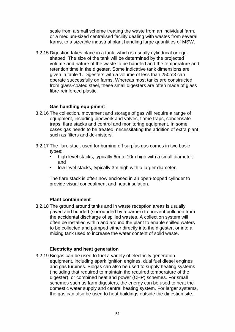
scale from a small scheme treating the waste from an individual farm, or a medium-sized centralised facility dealing with wastes from several farms, to a sizeable industrial plant handling large quantities of MSW.
3.2.15 Digestion takes place in a tank, which is usually cylindrical or egg-
shaped. The size of the tank will be determined by the projected volume and nature of the waste to be handled and the temperature and retention time in the digester. Some indicative tank dimensions are given in table 1. Digesters with a volume of less than 250m3 can operate successfully on farms. Whereas most tanks are constructed from glass-coated steel, these small digesters are often made of glass fibre-reinforced plastic.
Gas handling equipment 3.2.16 The collection, movement and storage of gas will require a range of
equipment, including pipework and valves, flame traps, condensate traps, flare stacks and control and monitoring equipment. In some cases gas needs to be treated, necessitating the addition of extra plant such as filters and de-misters.
3.2.17 The flare stack used for burning off surplus gas comes in two basic
types: • high level stacks, typically 6m to 10m high with a small diameter;
and • low level stacks, typically 3m high with a larger diameter.
The flare stack is often now enclosed in an open-topped cylinder to provide visual concealment and heat insulation.
Plant containment 3.2.18 The ground around tanks and in waste reception areas is usually
paved and bunded (surrounded by a barrier) to prevent pollution from the accidental discharge of spilled wastes. A collection system will often be installed within and around the plant to enable spilled waters to be collected and pumped either directly into the digester, or into a mixing tank used to increase the water content of solid waste.
Electricity and heat generation 3.2.19 Biogas can be used to fuel a variety of electricity generation
equipment, including spark ignition engines, dual fuel diesel engines and gas turbines. Biogas can also be used to supply heating systems (including that required to maintain the required temperature of the digester), or combined heat and power (CHP) schemes. For small schemes such as farm digesters, the energy can be used to heat the domestic water supply and central heating system. For larger systems, the gas can also be used to heat buildings outside the digestion site.
51

Sewage gas 3.2.20 Anaerobic digesters installed at municipal sewage works typically
range in volume from 180m3 to 3,400m3. The tank can be as high as 15 metres, although it can sometimes be partly buried. In addition to reducing the visual impact, partial burial offers heat insulation benefits and so reduces the energy demand of the digestion process.
Landfill gas 3.2.21 Most landfill sites containing biodegradable organic matter will produce
landfill gas (LFG) through a complex process of microbial decomposition. The period of time over which LFG is actively produced will vary according to local conditions. Under favourable conditions, substantial gas generation from a large municipal landfill site would probably be complete within 25-30 years. However, many factors control the decomposition process, including the proportion and nature of the organic material in the waste, moisture content, temperature, acidity, and the design and management of the site. These in turn affect the quantity and composition of gas produced.
Gas collection and management 3.2.22 Many landfill sites are already equipped with LFG collection and control
systems to prevent the gas from dispersing. The gas is piped to an extraction plant on the edge of the landfill site. The plant will typically include: • gas conditioning equipment; • extraction pumps; • a flare stack; • pipework and valves; and • control and monitoring equipment.
3.2.23 Gas is drawn from the waste via vertical and/or horizontal wells, each
of which is monitored and regulated. It is then conveyed to the extraction plant, usually in polyethylene pipes placed underground. LFG comes out of a landfill site warm and saturated with moisture. As it cools in the extraction pipework, liquid condenses out. The pipework is therefore laid at a gradient and incorporates condensate traps to remove this liquid from the gas flow. The type of gas conditioning equipment required depends on the use to which the gas will be put: gas for heat generation does not need to be purified as much as that used for electricity generation.
3.2.24 At any landfill site a flare stack is required to mitigate emission of
methane, which will be generated regardless of whether there is energy recovery or not. Where engines are installed the flare will be used where there is excess production or during servicing. In visual terms, flares can be either open (where a luminous flame will be observable) or closed (where the flame will be shrouded).
52
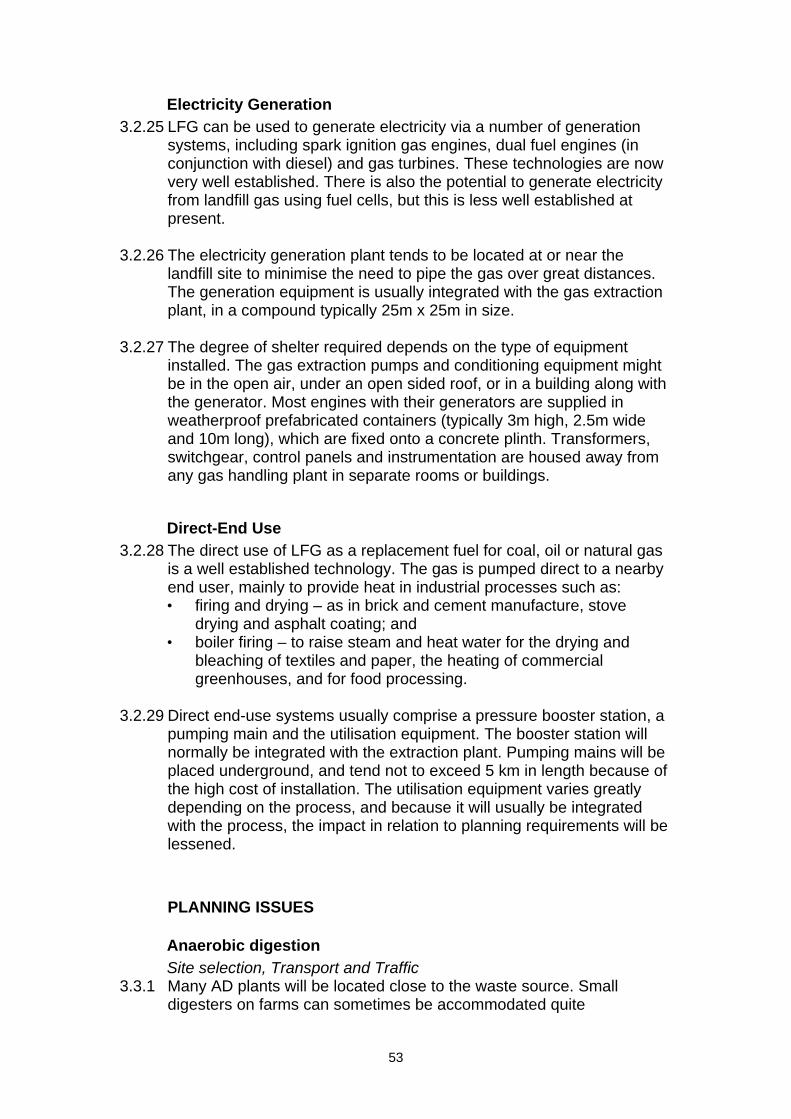
Electricity Generation 3.2.25 LFG can be used to generate electricity via a number of generation
systems, including spark ignition gas engines, dual fuel engines (in conjunction with diesel) and gas turbines. These technologies are now very well established. There is also the potential to generate electricity from landfill gas using fuel cells, but this is less well established at present.
3.2.26 The electricity generation plant tends to be located at or near the
landfill site to minimise the need to pipe the gas over great distances. The generation equipment is usually integrated with the gas extraction plant, in a compound typically 25m x 25m in size.
3.2.27 The degree of shelter required depends on the type of equipment
installed. The gas extraction pumps and conditioning equipment might be in the open air, under an open sided roof, or in a building along with the generator. Most engines with their generators are supplied in weatherproof prefabricated containers (typically 3m high, 2.5m wide and 10m long), which are fixed onto a concrete plinth. Transformers, switchgear, control panels and instrumentation are housed away from any gas handling plant in separate rooms or buildings.
Direct-End Use 3.2.28 The direct use of LFG as a replacement fuel for coal, oil or natural gas
is a well established technology. The gas is pumped direct to a nearby end user, mainly to provide heat in industrial processes such as: • firing and drying – as in brick and cement manufacture, stove
drying and asphalt coating; and • boiler firing – to raise steam and heat water for the drying and
bleaching of textiles and paper, the heating of commercial greenhouses, and for food processing.
3.2.29 Direct end-use systems usually comprise a pressure booster station, a
pumping main and the utilisation equipment. The booster station will normally be integrated with the extraction plant. Pumping mains will be placed underground, and tend not to exceed 5 km in length because of the high cost of installation. The utilisation equipment varies greatly depending on the process, and because it will usually be integrated with the process, the impact in relation to planning requirements will be lessened.
PLANNING ISSUES
Anaerobic digestion Site selection, Transport and Traffic
3.3.1 Many AD plants will be located close to the waste source. Small digesters on farms can sometimes be accommodated quite
53
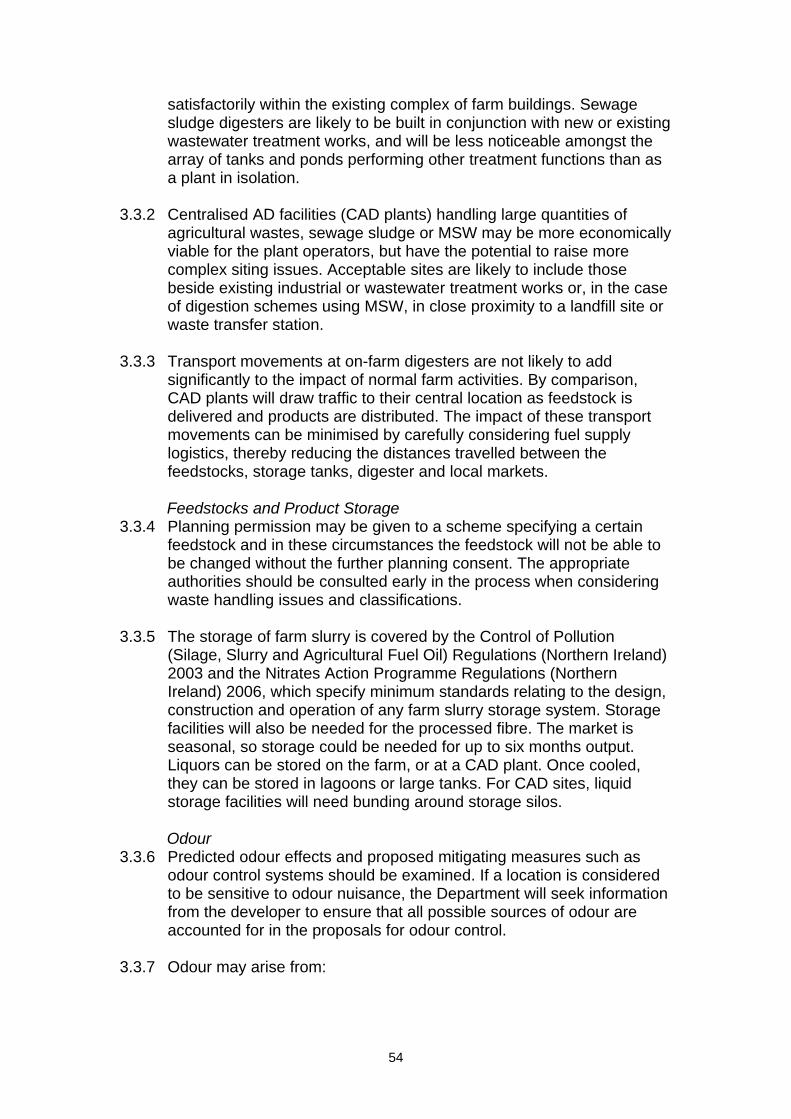
satisfactorily within the existing complex of farm buildings. Sewage sludge digesters are likely to be built in conjunction with new or existing wastewater treatment works, and will be less noticeable amongst the array of tanks and ponds performing other treatment functions than as a plant in isolation.
3.3.2 Centralised AD facilities (CAD plants) handling large quantities of
agricultural wastes, sewage sludge or MSW may be more economically viable for the plant operators, but have the potential to raise more complex siting issues. Acceptable sites are likely to include those beside existing industrial or wastewater treatment works or, in the case of digestion schemes using MSW, in close proximity to a landfill site or waste transfer station.
3.3.3 Transport movements at on-farm digesters are not likely to add
significantly to the impact of normal farm activities. By comparison, CAD plants will draw traffic to their central location as feedstock is delivered and products are distributed. The impact of these transport movements can be minimised by carefully considering fuel supply logistics, thereby reducing the distances travelled between the feedstocks, storage tanks, digester and local markets.
Feedstocks and Product Storage
3.3.4 Planning permission may be given to a scheme specifying a certain feedstock and in these circumstances the feedstock will not be able to be changed without the further planning consent. The appropriate authorities should be consulted early in the process when considering waste handling issues and classifications.
3.3.5 The storage of farm slurry is covered by the Control of Pollution
(Silage, Slurry and Agricultural Fuel Oil) Regulations (Northern Ireland) 2003 and the Nitrates Action Programme Regulations (Northern Ireland) 2006, which specify minimum standards relating to the design, construction and operation of any farm slurry storage system. Storage facilities will also be needed for the processed fibre. The market is seasonal, so storage could be needed for up to six months output. Liquors can be stored on the farm, or at a CAD plant. Once cooled, they can be stored in lagoons or large tanks. For CAD sites, liquid storage facilities will need bunding around storage silos.
Odour
3.3.6 Predicted odour effects and proposed mitigating measures such as odour control systems should be examined. If a location is considered to be sensitive to odour nuisance, the Department will seek information from the developer to ensure that all possible sources of odour are accounted for in the proposals for odour control.
3.3.7 Odour may arise from:
54
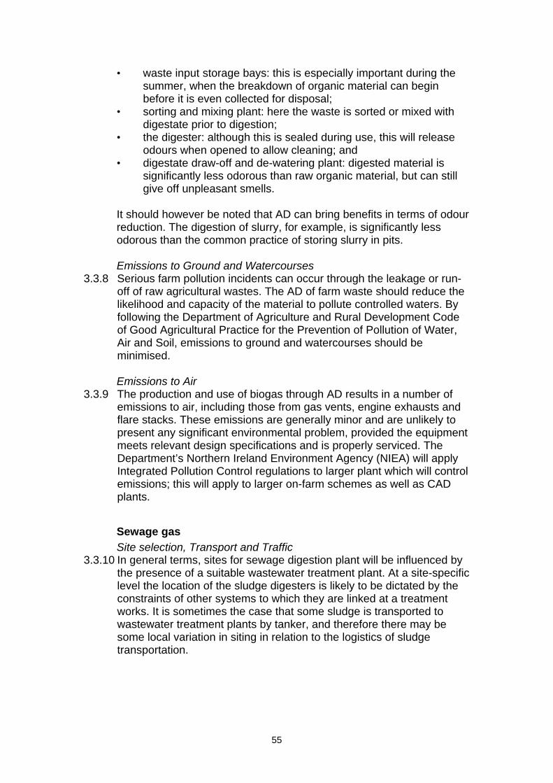
• waste input storage bays: this is especially important during the summer, when the breakdown of organic material can begin before it is even collected for disposal;
• sorting and mixing plant: here the waste is sorted or mixed with digestate prior to digestion;
• the digester: although this is sealed during use, this will release odours when opened to allow cleaning; and
• digestate draw-off and de-watering plant: digested material is significantly less odorous than raw organic material, but can still give off unpleasant smells.
It should however be noted that AD can bring benefits in terms of odour reduction. The digestion of slurry, for example, is significantly less odorous than the common practice of storing slurry in pits.
Emissions to Ground and Watercourses
3.3.8 Serious farm pollution incidents can occur through the leakage or run-off of raw agricultural wastes. The AD of farm waste should reduce the likelihood and capacity of the material to pollute controlled waters. By following the Department of Agriculture and Rural Development Code of Good Agricultural Practice for the Prevention of Pollution of Water, Air and Soil, emissions to ground and watercourses should be minimised.
Emissions to Air
3.3.9 The production and use of biogas through AD results in a number of emissions to air, including those from gas vents, engine exhausts and flare stacks. These emissions are generally minor and are unlikely to present any significant environmental problem, provided the equipment meets relevant design specifications and is properly serviced. The Department’s Northern Ireland Environment Agency (NIEA) will apply Integrated Pollution Control regulations to larger plant which will control emissions; this will apply to larger on-farm schemes as well as CAD plants.
Sewage gas Site selection, Transport and Traffic
3.3.10 In general terms, sites for sewage digestion plant will be influenced by the presence of a suitable wastewater treatment plant. At a site-specific level the location of the sludge digesters is likely to be dictated by the constraints of other systems to which they are linked at a treatment works. It is sometimes the case that some sludge is transported to wastewater treatment plants by tanker, and therefore there may be some local variation in siting in relation to the logistics of sludge transportation.
55
Feedstocks and Product Storage 3.3.11 Sewage sludge is not generally stored in liquid form for extended
periods of time. There are however usually intermediate storage tanks which act as buffers for variations in flow or input from sludge tankers.
Odour
3.3.12 Given that sewage sludge digesters are normally located at wastewater treatment works, odour emissions are likely to be dominated by the primary treatment processes (settlement/aerobic treatment), which usually take place in open tanks.
Emissions to Air, Ground and Watercourses
3.3.13 Issues will be broadly the same as those described under anaerobic digestion. They are likely to be addressed as part of the collection of operations of a wastewater treatment works.
Landfill gas Site selection
3.3.14 LFG plant should be located away from housing and other sensitive land uses, for reasons of safety and amenity (including potential noise). In practice this separation will rarely be difficult to achieve, given the large scale of landfill sites and the fact that they are generally situated away from residential areas.
3.3.15 The visual impact of a landfill gas generation scheme may be relatively
insignificant if it is co-located with other activities such as waste disposal on a site adjacent to a completed landfill. If, alternatively, extraction and landfill works have ended and the site is undergoing restoration, the Department may wish to consider the need for mitigating measures to reduce any visual intrusion caused by the plant.
Odour and emissions
3.3.16 The statutory definition of the combustion process specifies that “‘fuel’ does not include gas produced by the biological degradation of waste”. As such, the emissions from typical LFG plant are not currently regulated. Landfill gas fuelled generators may be regulated under EU stationary engines regulations in the near future. This is expected to result in a tightening of emissions limits.
INFORMATION TO ACCOMPANY A PLANNING APPLICATION
Anaerobic digestion 3.4.1 A planning application for an anaerobic digestion plant could usefully
include the following: • site plan and elevation drawings to help determine visual impact; • photomontage of digester, plant building(s) and chimney stack with
clear indication of building material;
56
• information on grid connection works, including transformer and transmission lines;
• details of potential noise or emissions to air and an assessment of their impact;
• details of vehicular access and vehicular movement; • landscaping provisions; • site management measures during the construction phase; • model of emissions dispersion; and • community consultation plans.
Sewage gas 3.4.2 An application for a sewage digestion plant could, in addition to the
above, include reference to the existing wastewater treatment plant.
Landfill gas 3.4.3 An application for a landfill gas plant could, in addition to the
information listed above, note that the LFG plant would require the addition of a powerhouse to a typical landfill site.
Environmental Impact Assessment 3.4.4 Developments that use waste to produce energy may require EIA.
Such projects could fall within projects listed in Schedule 2.3 and/or 2.11 to the Planning (Environmental Impact Assessment) Regulations (Northern Ireland) 1999.
OTHER AUTHORISATIONS/CONSENTS 3.5.1 Dependent upon the level of energy generation and the details of the
facility, the operations may require any of the following authorisations/consents: • DETI consent for electricity generation over 10MW • Abstraction License • Pollution Control • Waste Management License
57
4. Energy from Waste (Thermal processes)
INTRODUCTION 4.1.1 There are various technological configurations adopted to extract
energy from waste. These can be broadly subdivided into thermal and biological processes. Biological processes are covered under Section 3, while this section relates to the thermal processes, which use a high temperature process to release the chemical energy in the fuel.
4.1.2 This section offers guidance on types of thermal plant used to extract
energy from the biodegradable fraction of waste. It discusses their main characteristics, the basic technology and their environmental implications. The Northern Ireland Renewables Obligation Order definition is adopted here as the definition of what constitutes renewable energy in relation to energy from waste, and this is defined below.
Municipal Solid Waste 4.1.3 Municipal solid waste (MSW) is the term used to describe those wastes
gathered from domestic and commercial premises by the local waste collection authority. The quantity of MSW available is broadly proportional to the population of an area, but its composition will be affected by local factors such as the method of waste collection and the extent of waste recycling.
Business waste 4.1.4 Non-hazardous industrial and commercial waste arisings in the UK
have been estimated to be around 25 million tonnes per year, consisting mostly of paper, cardboard, wood and plastics. The disposal route for the bulk of this waste is landfill, although a small amount is incinerated along with MSW. In general, non-hazardous business waste can be preprocessed in similar ways to MSW to enable combustion using a range of technologies.
Other relevant wastes 4.1.5 The main types of other wastes suitable for energy from waste
schemes are as follows: Sewage sludge: in 1999 (latest available figures) the UK produced 1.13million tonnes of sludge (dry solids). This corresponds to an average of about 20kg generated by each person and may be considered for combustion or other thermal processes for the disposal of this material. Wood processing waste: small quantities of processed wood waste are produced by the furniture industries and can be classed as renewable, in their uncontaminated form.
58
Waste arisings and collection 4.1.6 The source and collection method of the waste material affects the
scope for using it in energy generation. MSW arisings are spread through an area, and are collected by local authorities or their contractors and taken to disposal sites. Other wastes arise at specific locations and lend themselves to small-scale energy schemes. There are economies of scale with larger more centralised plants.
Implications of the Renewables Obligation 4.1.7 Only those installations that are eligible to receive Renewables
Obligation Certificates (ROCs) under The Renewables Obligation Order (Northern Ireland) 20096 (the NIRO Order) are counted as renewable energy generation in the context of this document. Other proposals for energy from waste will be assessed under the provisions of PPS 11 ‘Planning and Waste Management’.
4.1.8 The NIRO Order provides that the biomass fraction of waste will be
eligible for ROCs. ‘Biomass’ is defined here as a fuel of which at least 90% of the energy content is derived from plant or animal matter or substances derived directly or indirectly there from (whether or not such matter or substances are waste) and includes agricultural, forestry or wood wastes or residues, sewage, fungi, algae, and energy crops.
4.1.9 A generating station which is fired wholly or partly from waste is
excluded from receiving ROCs unless: • the waste is biomass in accordance with the above definition; or • the waste is in the form of a liquid or gaseous fuel produced by
advanced conversion technologies (e.g. pyrolysis and gasification); or
• the station is a Combined Heat and Power (CHP) station accredited under the CHP Quality Assurance Standard.
4.1.10 In accordance with this definition, conventional waste incinerators firing
MSW will not be able to claim ROCs for the electricity they generate.
TECHNOLOGY 4.2.1 Conventional incineration and the advanced technologies defined in
the Renewables Obligation above are the two technology routes most likely to be used to recover energy from solid waste in the short to medium term. The provisions of the Renewables Obligation may increase substantially the numbers of Energy from Waste installations using advanced processes in the future.
6 The Renewables Obligation Order (Northern Ireland) 2009 (S.R 2009 No. 154)
59
Direct combustion 4.2.2 The majority of MSW incinerators burn the waste stream essentially in
the form it is collected. This process is called direct combustion. The combustion gases are cleaned in a sequence of processes which remove particulates, acid gases and trace organic compounds. The ash exits the process as two distinct streams – bottom ash that falls from the combustion grate, and fly ash that is separated from the flue gases. Bottom ash is considered to be inert and, after the separation of metals, is often used as an aggregate in the roads and construction industry. Fly ash can contain heavy metal contamination and so should be disposed of in a controlled hazardous waste landfill.
Pyrolysis 4.2.3 In recent years the concepts of waste pyrolysis and gasification have
received considerable attention and a number of companies are offering systems for commercial installation. Pyrolysis is the process of heating fuel in the absence of air to produce charcoal and a gaseous fuel (‘syngas’). These can then be burned in boilers, engines or turbines to generate heat and power. Plants with pyrolysis only are less common than those where pyrolysis is combined with gasification.
Gasification 4.2.4 Gasification is a process of partial combustion, which enables
operators to effectively control the temperature of the process, with consequent mitigation of pollutants. A gas is formed when the fuel reacts with sufficient oxygen to maintain a high reaction temperature but with insufficient oxygen to complete combustion. This gas can then be used in engines, boilers or turbines to generate power.
4.2.5 For all these processes the useful energy in the waste is generally
released by combustion, although increasingly syngas from pyrolysis and gasification is being used as a source of hydrogen for fuel cells. In the context of fuel cells, pyrolysis and gasification as processes have the advantage of producing a homogeneous gas from which hydrogen can be extracted.
4.2.6 Pyrolysis and gasification are still developing but experience thus far
has demonstrated that the superior control of the combustion offered by these processes can create lower levels of contaminants in the exhaust gas when compared with typical grate combustion.
4.2.7 Waste can be pre-treated in a variety of ways to improve its
combustion efficiency and extract recyclable materials such as metal and glass. Treatments include shredding, sorting and separation, and drying. The equipment used for sorting waste will typically include rotating and vibrating screens, magnetic separators, air separators and manual picking belts. Some more innovative systems use high temperature washing. The pressure from recycling targets has already
60
resulted in an increase in materials recovery facilities and in future these may well be co-located with Energy from Waste installations.
Combined Heat and Power 4.2.8 The most efficient Energy from Waste schemes generate both
electricity and heat, through Combined Heat and Power (CHP) plants. This method is particularly beneficial as most of the energy in the waste can be put to good use and the improvement in energy efficiency leads to a corresponding reduction in emissions. It is desirable for CHP and Community Heating Schemes to be situated close to local energy users in order to minimise the costs of the heat distribution system.
4.2.9 A typical waste-fuelled combined heat and power process will involve
some or all of the following: • waste reception and storage; • waste processing, material sorting and recovery; • feeding waste into the combustion, pyrolysis or gasification
chamber; • the combustion, pyrolysis or gasification reactor itself; • generation of heat and power using steam turbines, gas engines or
gas turbines; • treating the waste gases to reduce emissions; • handling, storage and disposal of ash; and, • handling, storage and disposal of liquid effluents such as boiler
water and surface water.
Scale of development 4.2.10 Energy from Waste plants vary in size from small installations (serving
factories for example) to large-scale MSW plants. New projects therefore might either be accommodated within existing or converted buildings, or may require large new sites.
4.2.11 The costs of meeting stringent licensing standards mean that MSW
plants using incineration need to achieve economies of scale to be viable. Incinerators in the UK have a waste throughput of in the region of 100,000 to 600,000 tonnes per year. A MSW plant consuming 400,000 tonnes of waste per year will produce approximately 34MW of electricity, enough to supply about 64,000 homes.
Disposal of ash and gas cleaning residues 4.2.12 There are two types of ash from conventional incinerators. The ash that
falls from the combustion grate (bottom ash) is inert and can often be used as an aggregate in the roads and construction industry. The ash from the flue gas cleaning installation contains heavy metals and traces of other contaminants and should be sent to controlled landfill. The ash from gasification and pyrolysis plants may contain a higher carbon content but this is not thought to be harmful as the carbon is in its
61
elemental form and inert. Heavy metals will still be found in the finer ash and may need disposal in controlled landfill. This will depend upon the process and appropriate treatment of this ash will be a condition of the licence to operate.
PLANNING ISSUES
Siting issues 4.3.1 The siting of an Energy from Waste plant is likely to be influenced by
the following factors: • the source of the waste; • the economic implications of transporting the waste and disposal of
any associated by-products; • site access; and • proposed energy use, the availability of local heat markets and
ease of connection to the electricity distribution network. 4.3.2 In general, waste treatment and disposal operations are characterised
to a large extent by the high volume of materials entering and exiting the site. In order to minimise the adverse environmental effects of transporting waste, they should, wherever possible, be located close to the waste source. The optimum locations for most MSW and business waste plants are therefore likely to be in or very close to urban areas.
4.3.3 The Department will take into account the waste management plans
being drawn up for the Region. These should identify the spare capacity at existing plants, sites for new waste management plants, or areas of search for new sites. They should also set out the land-use criteria against which planning applications for new waste management development will be assessed.
Visual Effects 4.3.4 In many cases, Energy from Waste developments are likely to be
proposed in industrial areas, where they will be broadly in keeping with the existing buildings. Even so, the developments can be prominent features, and therefore the Department will expect a high standard of design and landscaping in order to minimise their visual impact.
4.3.5 Chimney height will vary depending on a number of factors, including
the scale of plant, its capacity, local conditions and on occasion, the technology used. Pyrolysis and gasification plant generally need lower stack heights than incineration. Ultimately chimney height will be determined by pollution control procedures under the Pollution Prevention and Control Regulations (Northern Ireland) 2003 or the Clean Air (Northern Ireland) Order1981, to ensure adequate dispersal of emissions in the exhaust gas.
62
Ambient air quality and odour 4.3.6 A plant that complies with licence requirements for air pollution might
still give rise to odours. For large projects, such as MSW incinerators, odour is covered under the PPC Regulations administered by the Northern Ireland Environment Agency (NIEA), and for smaller projects it is covered under District Council PPC permits. The sources of odour nuisance may not always be emissions through chimneys and vents from the works, but could arise from open-air storage, handling or transport of waste materials or their products. In considering proposals, it should be borne in mind that some problems may be created by odour, particularly where a site is close to housing or other odour-sensitive land uses such as a school. In addition emissions from EfW plants and traffic movements associated with larger plant should be assessed taking account of any Local Air Quality Plans drawn up by District Councils.
Dust 4.3.7 With the exception of particulates from stacks, most dust is created
during waste processing and ash handling operations. Practical measures for dust control include minimising, or eliminating open-air storage, water sprinkling and transportation within covered skips or lorries. On-site processing of ash can also significantly assist dust control. Emission levels are regulated through the Department’s Northern Ireland Environment Agency (NIEA) or the terms of a site’s Waste Management Licence.
Emissions to water 4.3.8 Water bodies may be affected either by emissions entering from the
atmosphere or the by certain liquid effluents created by particular processes. The main sources of liquid effluent will be from gas cleaning systems, cooling water and surface run off. NIEA has responsibility for the control of water quality. The Department of Agriculture and Rural Development’s Rivers Agency will need to be consulted if it is proposed that river water is used for cooling. The Loughs Agency may need to be consulted for proposals affecting the Foyle and Carlingford catchments.
INFORMATION TO ACCOMPANY A PLANNING APPLICATION 4.4.1 A planning application for a thermal Energy from Waste plant could
usefully include the following: • site plan and elevation drawings to help determine visual impact; • photomontage of plant building(s) and chimney stack with clear
indication of building material; • information on grid connection works, including transformer and
transmission lines; • details of air and noise emissions and an assessment of their
impacts;
63
• details of vehicular access and vehicular movement; • landscaping provisions; • site management measures during the construction phase; and • model of emissions dispersion.
Environmental Assessment 4.4.2 Developments that use waste to produce energy may require EIA.
Such projects could fall within projects listed in Schedule 2.3 and/or 2.11 to the Planning (Environmental Impact Assessment) Regulations (Northern Ireland) 1999.
OTHER AUTHORISATIONS/CONSENTS 4.5.1 Dependent upon the level of energy generation and the details of the
facility, the operations require any of the following authorisations/consents: • DETI consent for electricity generation over 10MW • Waste Incineration Directive • Pollution Control • Ambient Air Quality/Odour
64
5. Small Hydro
INTRODUCTION 5.1.1 Hydropower is well developed in Great Britain, where most sites with a
potential greater than 1MW have already been developed. However, there is the potential for the development of sites in Northern Ireland in the range of 100kW (0.1MW) to 500kW (0.5MW), and the possibility for a few sites of up to 1MW, which could be economically developed as grid connected schemes. In addition, there are a larger number of locations where smaller, domestic scale schemes in the range 10kW to 50kW could be developed. This section deals with smaller hydro schemes of up to 1MW.
TECHNOLOGY 5.2.1 The technology for harnessing waterpower is well established. Water
flowing from a higher to a lower level is used to drive a turbine, which produces mechanical energy. This mechanical energy is usually turned into electrical energy by a generator, or more rarely to drive a useful mechanical device.
5.2.2 The energy produced is directly proportional to the volume of water and
the vertical distance it falls. Thus, a similar amount of energy could be produced from a small volume of water falling over a long vertical distance (high head), as from a larger amount of water falling a much shorter vertical distance (low head).
5.2.3 The majority of schemes are likely to be ‘run of river’, where water is
taken from a river from behind a low weir, with no facility for water storage, and returned to the same watercourse after passing through the turbine. In addition, potential also exists for small hydro installed on existing reservoirs, but these may also be treated as ‘run of river’, as they do not involve the construction of a new impounding structure.
5.2.4 Pumped storage schemes are capable of being used in conjunction
with more intermittent forms of renewable energy to smooth out the intermittency by providing an element of energy storage. During periods of low demand, but when the prime resource is available, excess energy is used to pump water from a lower level to a higher level reservoir. During periods when demand is high and the prime resource availability is low, the water from the higher reservoir is released via a turbine to the lower reservoir to generate electricity. Such schemes may require the construction of two new reservoirs, but apart from this, the technology employed, and the implications for the planning system, are similar to those outlined in this section. However, because of the cost involved, pumped storage schemes of less than 1MW are likely to be extremely rare.
65
5.2.5 The essential elements of a hydro scheme are as follows: • a source of water that will provide a reasonably constant supply.
Sufficient depth of water is required at the point at which water is taken from the watercourse, and this is achieved by building a low weir (typically up to 2 metres high) across the watercourse. This is called the ‘intake’;
• a pipeline, often known as a penstock, to connect the intake to the turbine. A short open ‘headrace’ channel may be required between the intake and the pipeline, but long headrace channels are rare due to environmental and economic constraints;
• a building housing the turbine, generator and ancillary equipment – the ‘turbine house’.
• a ‘tailrace’ returning the water to the watercourse; and • a link to the electricity network, or the user’s premises.
These are explained below.
The Intake 5.2.6 The scale and nature of these elements depend on site conditions, and
whether the scheme is low head or high head. 5.2.7 The intake typically comprises a weir, up to 2 metres high, across the
watercourse. A spillway ensures that the downstream watercourse is never totally deprived of flow, and a screen or trashrack prevents floating debris or fish from entering the pipeline. A valve or sluicegate is often incorporated, and where the watercourse has a high silt load, a settling tank may be required. The Department’s Northern Ireland Environment Agency (NIEA), Land and Resource Management Unit should be consulted regarding disposal of debris from the trashrack.
The pipeline 5.2.8 The pipeline (sometimes called the penstock) connects the intake with
the turbine. This is typically a pipe of steel, plastic or composite material, the diameter of which could be between 10cm and 100cm, depending on the characteristics of the site, and the capacity of the scheme. High head schemes typically have smaller diameter pipes of longer length (sometimes over a kilometre), whereas low head schemes are typified by short, larger diameter pipes. Pipes are often buried for environmental or technical reasons. Anchor blocks to restrain the pipe are required at vertical and horizontal changes of direction, but these are usually buried if the pipe is buried.
5.2.9 Open headrace channels are now rare on new schemes, but may
occur if the project involves the rehabilitation of an existing scheme, particularly on old watermill sites.
66
The turbine house 5.2.10 The building houses the turbine, generator and ancillary equipment,
and is typically a single storey building of between 3 metres by 4 metres for a small domestic scheme, to 10 metres by 10 metres for a large grid connected scheme. Occasionally, particularly on old watermill sites, the machinery may be located in an existing building. Vehicular access to the turbine house is required for construction and maintenance purposes.
5.2.11 To minimise the length of the tailrace, and to maximise the available
head, the turbine house is usually located close to the watercourse.
The tailrace 5.2.12 After use, the water is returned to the natural watercourse via a
concrete or masonry channel connecting the turbine house to the watercourse. To avoid flooding the turbine, this channel should have a gradient sufficient to allow free discharge of water. A screen to prevent the ingress of fish should generally be incorporated. Occasionally the tailrace is an underground structure.
Electricity connection 5.2.13 When linking to the grid the connection between the turbine house and
the local electricity network is typically 3 wires, supported on single wooden poles.
The context 5.2.14 High head hydro sites require a significant fall and a significant
proportion of river flow. Development is therefore likely to take place in hilly or mountainous areas, many of which may be of landscape or nature conservation interest. This can be a potential barrier to small hydro development although careful consideration of all the benefits and disbenefits of a development is required. Small hydro schemes will seek to make the most efficient use of any site in terms of water abstraction to help maximise energy production. NIEA Water Management Unit will put stringent controls on the water abstraction regime, particularly where nature conservation interests are evident, and negotiations are required between all parties at an early stage in order to reach an acceptable solution.
5.2.15 The built elements of small hydro schemes should be small and of a
scale in keeping with the river valleys in which they are sited.
PLANNING ISSUES 5.3.1 The development of hydro-electric power generation schemes should
be achieved in a manner which is compatible with the many other uses
67
to which a river is put. Early liaison between the developer and the relevant statutory undertakers is essential to ensure that all statutory remits are met, and that proposals do not detract from the existing value and interest of the watercourse and its surroundings. There is some potential for environmental improvements through technical measures.
Siting and the landscape 5.3.2 As with several renewable sources of energy, it is usually only possible
to exploit hydropower resources where they occur. Hydro schemes do however enjoy modest locational flexibility as the precise siting of the intake and the turbine house can sometimes be influenced by non-operational factors, including local landscape characteristics.
5.3.3 Consideration should be given to integrating a new scheme into the
landscape as far as possible. Where rivers are lined with trees, for instance, it will be relatively simple to conceal hydropower facilities, particularly if the existing woodland cover is supplemented by new planting. Where the development is taking place in a more open location, built elements should either be designed to be as small as possible, having regard to operational considerations, or should be designed to be in keeping with local landscape and architectural features. In the case of schemes proposed for hillsides or other prominent locations, the landscape impact of the development in close and distant views should be appraised. Careful consideration should be given to burying the pipeline and restoration of the pipeline route.
5.3.4 In some cases, the visual appearance of waterfalls may be affected by
water abstraction. In these cases, consideration should be given to potential viewers, and to the importance of the waterfall in immediate and longer distance views. Assessment of effects can usefully include photographs of the waterfalls at various flows, as existing summer flows may match the proposed flows after abstraction during the wetter months. Measures could be adopted to overcome visual objections, such as requiring abstraction to be reduced during the day in summer months when visitors are most likely to be present.
5.3.5 Measures to minimise the visual impact of pipes and power lines
should also be considered carefully at the design and planning application stages.
Design Considerations 5.3.6 Although the hydro developments anticipated will generally be small in
scale, their waterside location will, in many cases, place them in areas valued for their visual and natural amenity. Such schemes can operate for many decades, and their principal built elements will often become a permanent feature in the landscape. In some circumstances, weirs,
68
fish ladders and turbine houses can become features of interest in their own right.
5.3.7 For these reasons, the Department will expect a high standard of
design. Particular attention should to be given to the architectural quality of built elements, the choice of building materials, and manner in which the development is integrated with its surroundings. Design schemes that are in harmony with their surroundings, perhaps incorporating vernacular building materials and styles will be encouraged.
Hydrological Considerations 5.3.8 During operation of a small hydro scheme, water is abstracted over a
short stretch of the river. The scheme does not pollute or consume water and usually returns the supply to the channel from which it was abstracted. Water that has passed through a turbine is often improved by aeration and is free of debris. NIEA will be consulted regarding the water extraction regime.
Ecological Considerations 5.3.9 The effect of water abstraction on the riverine ecology can be a
concern, particularly in areas that are valued or designated for their ecological resource. Where ecological issues are considered to be important, liaison between the developer, NIEA Natural Heritage and Water Management Unit, the Department for Culture Arts and Leisure and, where appropriate, the Loughs Agency will help to establish the required environmental information to be provided at the planning application stage, and the potential impacts that are to be considered. This may include surveys of river corridor and river beds habitats, bryophytes, fish, invertebrates, amphibians, birds and mammals. The effects of changed flow regimes and water quality may need to be assessed. It is possible that impacts can be ‘designed out’ of the scheme with measures such as pulsed flow or seasonal operating of the plant.
Fisheries interests 5.3.10 Fish can be killed or injured by hydropower schemes. This risk can be
minimised by careful design and adjustment of the seasonal operating schedule of the plant. Some types of turbine (such as low to medium head crossflow designs) can oxygenate the river water and may thereby benefit the fish population. Dams and weirs should include structures which allow free passage of migratory fish, and afford fish and other freshwater animals protection from the turbines while maintaining flows.
69
Noise 5.3.11 The noise emitted from a turbine should generally be well contained by
the turbine house and should not be heard more than a few metres away. However, in appropriate cases, for example if the site is close to residential properties, developers will be required to submit a noise assessment to accompany their proposal and they should consult with the local District Council’s Environmental Health Department.
Construction disturbance 5.3.12 In general, the construction impact of a hydro-power scheme will be no
different to that of other developments of similar size. However, construction on or beside a river will often cause the water to become clouded with silt or mud. Before granting planning permission for a hydro project, the Department may, in consultation with NIEA Water Management Unit, the Department of Agriculture and Rural Development’s (DARD) Rivers Agency and where appropriate the Loughs Agency, request that a developer specifies the site management measures that will be adopted to minimise this problem.
5.3.13 The construction of the pipeline and weir may have an impact on
sensitive habitats. In this instance the developer may be required to submit a detailed construction specification, and in areas designated for their nature conservation or ecological importance, an officer from NIEA may be required to be present on site during certain parts of the construction process. This can ensure that construction is carried out in a manner that is most sensitive to the ecology of the site.
Operational disturbance 5.3.14 Once in operation, small hydro schemes require little maintenance. A
weekly visit is usually all that is required, and a well-constructed remotely operated plant may demand less frequent visits. Depending on the design, daily cleaning of the trashrack may be required during autumn, but self-cleaning screens are increasingly common.
Recreation and Public Access 5.3.15 A small hydropower scheme will have a negligible impact on public
access, though fisheries interests or other users of the river might be affected. The pipeline route may often be designed to follow the route of an existing footpath alongside a river, but impacts will be confined to the construction stage of the project where temporary diversions or closure may be required.
INFORMATION TO ACCOMPANY A PLANNING APPLICATION 5.4.1 A planning application for a hydro development should, where
appropriate, include the following information:
70
• maps, diagrams and drawings showing the location and design of intake, pipeline, turbine and turbine house, weirs, tailrace and security fencing and lighting for urban schemes;
• details of air and noise emissions and an assessment of their impacts;
• photomontage of intake; • grid connection works, including transformer and transmission
lines; • provision for fish passes (where required); • information on environmental and biodiversity impacts; • details of vehicular access and vehicular movement; • landscaping provisions; and • measures for management of the site during the construction
phase and for long term maintenance.
Environmental Assessment 5.4.2 The Planning (Environmental Impact Assessment) Regulations
(Northern Ireland) 1999 include “installations for hydroelectric energy production” within Schedule 2(3)(i). Those with a generating capacity of over 500kW (0.5MW) must be screened for the need for EIA. Where a screening opinion is required, Schedule 3 to the EIA Regulations provides selection criteria for screening Schedule 2 development.
5.4.3 An EIA is often required by NIEA Water Management Unit as part of
the application for an Abstraction Licence. Consultation between statutory agencies at the scoping stage will minimise duplication of effort. In many cases, one Environmental Statement will be sufficient for both purposes.
OTHER AUTHORISATIONS/CONSENTS 5.5.1 In addition to planning permission, a hydro scheme may require any of
the following authorisations. • DETI consent for electricity generation over 10MW • Abstraction License • Consent to work in a water course
71

6. Active Solar (Photovoltaics)
INTRODUCTION 6.1.1 Active solar technology can be divided into two categories:
Photovoltaic (PV) and Solar Water Heating (SWH). Solar PV is unique among renewable energy technologies in that in addition to generating electricity from daylight, it can also be used as a building material in its own right. PV can either be roof mounted or free-standing in modular form, or integrated into the roof or facades of buildings through the use of solar shingles, solar slates, solar glass laminates and other solar building design solutions.
TECHNOLOGY 6.2.1 PV systems exploit the direct conversion of daylight into electricity in a
semi-conductor device.
6.2.2 The most common form of device comprises a number of semi conductor cells which are interconnected and encapsulated to form a solar panel or module. There is considerable variation in appearance, but many solar panels are dark in colour, and have low reflective properties. Solar panels are typically 0.5 to 1m2 having a peak output of 70 to 160 watts. A number of modules are usually connected together in an array to produce the required output, the area of which can vary from a few square metres to several hundred square metres. A typical array on a domestic dwelling would have an area of 9 to 18m2, and would produce 1 to 2 kW peak output.
6.2.3 Other forms of solar PV technology are becoming more common in the
UK, such as solar tiles, which can be integrated into new buildings or refurbishments alongside conventional roofing tiles or slates. They have the aesthetic advantage of giving a roof an homogeneous appearance, virtually indistinguishable from conventional roofing materials. PV modules can be fitted on top of an existing roof using a low support structure. In this case, the panels will typically lie flush with the existing roof and not protrude above the roofline. Alternatively, and particularly in new buildings, they may form all or part of the weatherproofing element of the roof, replacing conventional slates or tiles. Where the modules form only part of the area of the roof, they can be integrated in a similar way to proprietary skylights.
6.2.4 Connections between individual panels are made either in the support
structure, or inside the roof void, and are rarely visible from the exterior of the building.
72
Siting issues 6.2.5 For best performance, PV modules need to be inclined at an angle of
20-40 degrees, depending on the latitude, and orientated facing due south. In practical terms, this is not always possible on existing buildings, and some degree of flexibility in inclination and orientation is acceptable although this will be at the expense of best performance. To function well PV installations need to be inclined at between 10 and 60 degrees, and orientated facing from east to west (i.e. within 90 degrees of due south).
6.2.6 Although roof mounted PV is the most common, modules can also be
mounted on the sides of buildings, or on free standing support structures on the ground. In some cases, particularly on institutional or commercial buildings, PV cladding on the side of the building can be an architectural feature as well as a supply of electricity. Other examples of building integrated PV include external sun shading of office windows (bris-solaires) and glass atrium roofs.
6.2.7 Shadows from buildings, trees or other structures can significantly
reduce performance of the PV system and planners and designers should take reasonable steps to minimise permanent overshading of the PV.
Types of system 6.2.8 Stand-alone systems: PV is widely used to provide power for
communications systems, domestic dwellings and monitoring systems either in remote areas or locations where connection to the grid is expensive or otherwise problematic, e.g. certain road signage. Elsewhere in the UK, the use of PV to provide energy for lighting of telephone kiosks in rural areas, bus shelter lighting, remote traffic monitoring, and railway trackside signalling is increasing as it is almost always more cost-effective than new connections to the grid.
6.2.9 Grid-connected schemes: In grid-connected solar PV systems NIE
Energy (Northern Ireland Electricity) offers a ‘Renewable Generation Contract’ under which it offers small generators (up to 1MW capacity) a payment for both the NIROCs (Northern Ireland Renewable Obligation Certificates) on accredited generation and for electricity that is exported. Other contractual arrangements may be available through Second Tier Suppliers. Further information is available on the NIE Energy website http://www.nie-yourenergy.co.uk./micro.php.
The context 6.2.10 PV technology is expected to decrease in cost over the next decade
and PV systems could provide a useful contribution to renewable energy generation. For its part the Department would encourage greater use of PV systems in new developments and the retrofitting or
73
incorporation of such technology on existing buildings where appropriate.
PLANNING ISSUES
General 6.3.1 The technology will be familiar to most and from the planning point of
view, whilst there are clearly implications for listed buildings and the sensitive front elevations of some conservation areas, in general ‘solar panels’ are to be encouraged. In most cases involving dwelling houses, provided the building is not listed or in a conservation area and the installation complies with the relevant constraints, PV will be “permitted development” and a planning application will not be required. The panels cannot however, extend more than 15 centimetres beyond the plane of any existing roof slope which fronts any road to comply with Schedule 1 Part 1, Class B1(c) of the Planning (General Development) Order) Northern Ireland) 1993. It should be noted that permitted development rights for small-scale renewable energy development are currently under review by the Department.
6.3.2 PV is particularly well suited to the urban environment and is clean and
silent in operation.
6.3.3 The increasing take-up of solar PV technologies raises a number of considerations which may need to be taken into account. These include: • whether particular systems require planning permission; • the importance of siting systems in situations where they can
collect the most energy from the sun; • the need for sufficient area of solar modules to produce the
required energy output from the system; and • the colour and appearance of the modules.
Listed buildings and designated areas 6.3.4 The installation of a PV array on a building listed for its special
architectural merit or historic interest – or on another building or structure within its curtilage – is likely to require an application for listed building consent. This will be so, even if specific planning permission is unnecessary.
6.3.5 Permitted development rights to clad the walls or alter the existing
roofline of a dwelling do not necessarily apply in Areas of Outstanding Natural Beauty, Conservation Areas or Areas of Special Scientific Interest. When considering applications in these areas the potential impact on the character or appearance of the area should be considered.
74
6.3.6 If an application for a PV module is submitted for a building close to a conservation area, or close to a listed building, its proximity to such area or buildings may be a material consideration in deciding the application.
INFORMATION TO ACCOMPANY A PLANNING APPLICATION 6.4.1 A planning application or application for listed building consent for a
solar PV system could usefully include the following information: • the design of the module or array; • photographs of the existing built environment; • detail of the roof mounting arrangement, if applicable; • indicative drawings of the module or array in place; • connection details to the building or grid if relevant; • if the application involves a listed building, a photomontage of the
proposed collector array could be useful.
Environmental Assessment 6.4.2 The Planning (Environmental Impact Assessment) Regulations
(Northern Ireland) 1999 do not include solar energy systems specifically in Schedule 1 or 2. However any industrial scale installation for the production of electricity which exceeds 0.5 hectares is listed in Schedule 2 and would therefore require a Screening Opinion. Such large scale PV installations, however, are rare in the UK. Domestic or small-scale systems are not covered by Schedule 1 or 2 and are therefore not likely to require an EIA. In AONBs, conservation areas and on listed buildings, the only issues likely to be important are visual amenity and building fabric and these can be covered by a short description accompanying the planning application.
OTHER AUTHORISATIONS/CONSENTS
6.5.1 For stand-alone systems not connected to the distribution network, no additional authorisations are required. For systems that are connected to the electricity network, prior consent of NIE must be obtained in accordance with NIEs current connection process. Small PV systems come within the scope of Engineering Recommendation G83/1 – Recommendations for the Connection of Small Scale Embedded Generators (up to 16A per phase), in Parallel with Public Distribution Networks, (Issue 1: 2003). NIE have increased the limit of G83 applications to 6kW per phase. Larger systems may be required to meet Engineering Recommendation G59/1/NI – Recommendations for the connection of embedded generating plant to Northern Ireland Electricity’s distribution systems. Schemes for 10MW or more of electricity generation will require DETI consent.
6.5.2 There may be instances where the retrofitting of solar panels to an
existing building will require building control consent.
75
7. Solar Thermal (Solar Water Heating)
INTRODUCTION 7.1.1 Active solar technology can be divided into two categories:
Photovoltaic (PV) and Solar Water Heating (SWH). The technologies appear to be similar, in that they both use roof mounted equipment to collect radiation from the sun and convert it to a useful form of energy, but they produce two different things: electricity in the case of PV and hot water in the case of Solar Water Heating. This section deals with Solar Water Heating, and describes the basic technology and applications. Some sections are common to both sections: the repetition between them is intentional.
7.1.2 Solar water heating systems can be used to heat water for a variety of
purposes. Amongst the most common are domestic use, light industrial and agricultural use and the heating of swimming pools. At present, the widest use is in the residential domestic hot water sector. SWH systems are occasionally used to provide space heating.
7.1.3 There is a common misconception that solar water heating is
ineffective in the UK for climatic reasons. Whilst it is clearly not as effective in the UK as it could be in Spain for instance, a good modern system will make a significant contribution to water heating requirements. The domestic sector is an obvious priority – a well-designed system should provide 50–60% of annual domestic hot water requirements, with most of this energy capture being between May and September.
TECHNOLOGY 7.2.1 The key component in a solar water heating system is the collector.
Two main types are common in the UK: flat plate collectors and evacuated tube collectors. In both types, radiation from the sun is collected by an absorber, and is transferred as heat to a fluid, which may be either water, or a special fluid employed to convey the energy to the domestic system using a heat exchanger.
Flat plate collectors 7.2.2 Flat plate collectors comprise a water filled metal ‘envelope’ with a
special black coating which improves absorption of solar energy and heat transfer. This is housed in a glazed, insulated box. The collector is connected to the hot water system of the building in a similar way to a conventional boiler, usually using an indirect coil in the hot water cylinder. Water is circulated either by thermo-syphon or, more commonly using a circulating pump. The pump is controlled in such a way that when the temperature of the collector is lower than the temperature in the hot water system, the pump is switched off. Flat
76
plate collectors need to be protected against frost, and this is effected either by the addition of antifreeze to the heating circuit, or by arranging the system such that the collector ‘drains down’ when the pump is switched off.
7.2.3 A type of flat plate collector has the storage cylinder as an integral part
of the collector, mounted on the roof. Although common in warmer climates these are rare in the UK, and normally the only part of the installation that is visible is the collector.
Evacuated tube collectors 7.2.4 Evacuated tube collectors comprise a number of vacuum tubes,
typically around 100mm in diameter, and 2 metres in length containing a finned metal collector tube. Each tube is filled with a heat transfer fluid, and the upper ends of individual tubes are connected to a manifold heat exchanger, which is connected to the hot water system of the building as in the case of flat plate collectors. Evacuated tube collectors do not require protection against frost.
7.2.5 Although both types of collector will collect more energy during summer
months, a significant amount of energy will also be collected on cold winter days.
Installation 7.2.6 The collector, glazing and insulation are generally mounted in a box
which is usually grey or black in colour and typically 1-2m2 in area. For an average residential domestic installation, some 4 or 5m2 of flat plate collector, or some 3m2 of evacuated tube are required. Typically, this would be mounted on a southerly facing roof pitch, or more rarely on a free-standing tilted frame on the ground, or a flat roof. Increasingly, collectors are becoming available that can be incorporated into a new or existing roof in much the same way as proprietary roof windows. Some systems use photovoltaics (PV) to provide power for the system pump. In this case, a separate PV module, typically 20cm by 40cm will be mounted adjacent to the solar hot water collector.
7.2.7 Collectors rarely project more than 120mm above the existing roofline.
Connecting pipework is normally run from the back of the collector directly through to the roof void, and is not normally visible from the exterior of the building. Solar water heating collectors for swimming pools generally comprise a mat of neoprene, or other black rubberised material that is mounted near to the swimming pool. Typically this will have an area of about half that of the surface area of the pool. The collector may be mounted on the roof of an adjacent low building (such as a garage), or more commonly on a low ground mounted frame. The collector is often mounted flat, or only slightly inclined with the outlet higher than the inlet.
77
Siting issues 7.2.8 For best performance, solar water heating collectors need to be
inclined at an angle of 30-40 degrees, depending on the latitude, and orientated facing due south. In practical terms, this is not always possible on existing buildings, and some degree of flexibility in inclination and orientation is acceptable although this will be at the expense of best performance. To function satisfactorily collectors can be inclined at between 10 and 60 degrees, and orientated facing from east to west (i.e. within 90 degrees of due south).
7.2.9 Although roof mounted collectors are the most common, they can also
be mounted on the sides of buildings, or on free standing support structures on the ground. The latter is particularly common in the case of swimming pool heaters.
7.2.10 Shadows from buildings, trees or other structures can significantly
reduce performance of solar hot water collectors, and planners and designers should take reasonable steps to minimise overshadowing.
The context 7.2.11 Solar water heating is a mature and recognised technology. A domestic
system is within the economic means of many households in the UK, and the technology could provide a useful contribution to renewable energy generation. For its part the Department would encourage greater use of SWH systems in new developments and the retrofitting or incorporation of such technology on existing buildings where appropriate. PLANNING ISSUES
General 7.3.1 The technology will be familiar to most and from the planning point of
view, whilst there are clearly implications for listed buildings and the sensitive front elevations of some conservation areas, in general solar water heating systems are to be encouraged. In most cases involving dwelling houses, provided the building is not listed or in a conservation area and the installation complies with the relevant constraints, SWH systems will be “permitted development” and a planning application will not be required. The SWH collectors cannot however, extend more than 15 centimetres beyond the plane of any existing roof slope which fronts any road to comply with Schedule 1 Part 1, Class B1(c) of the Planning (General Development) Order) Northern Ireland) 1993. It should be noted that permitted development rights for small-scale renewable energy development are currently under review by the Department.
78
7.3.2 Solar hot water systems have some advantage over other renewable energy technologies, in that they are well suited to the urban environment: they are generally silent in operation and release no emissions.
7.3.3 The development of systems for collecting and using solar energy
raises a number of considerations which may need to taken into account. These include: • whether particular systems require planning permission; • the importance of siting systems in situations where they can
collect the most energy from the sun; • the need for sufficient area of solar modules to produce the
required energy output from the system; and • the colour and appearance of the modules.
Listed Buildings and designated areas 7.3.4 The installation of solar water heating collectors on a building listed for
its special architectural merit or historic interest – or on another building or structure within its curtilage – is likely to require an application for listed building consent. This will be so, even if specific planning permission is unnecessary.
7.3.5 Permitted development rights to clad the walls or alter the existing
roofline of a dwelling do not necessarily apply in Areas of Outstanding Natural Beauty, Conservation Areas and Areas of Special Scientific Interest. When considering applications in these areas the potential impact on the character or appearance of the area should be considered.
7.3.6 If an application for a SWH system is submitted for a building close to a
conservation area, or close to a listed building, its proximity to such area or buildings may be a material consideration in deciding the application.
INFORMATION TO ACCOMPANY A PLANNING APPLICATION 7.4.1 A planning application or application for listed building consent for a
solar hot water system could usefully include the following information: • the design of the collector; • photographs of the existing built environment; • detail of the roof mounting arrangement, if applicable; • indicative drawings of the collector in place; and • if the application involves a listed building, a photomontage of the
proposed collector could be useful.
79

Environmental Assessment 7.4.2 The Planning (Environmental Impact Assessment) Regulations
(Northern Ireland) 1999 do not include solar energy systems specifically in Schedule 1 or 2 and domestic or small-scale solar water heating collectors are therefore not likely to require an EIA. In AONBs, conservation areas and on listed buildings, the only issues likely to be important are visual amenity and building fabric and these can be covered by a short description accompanying the planning application.
OTHER AUTHORISATIONS/CONSENTS
7.5.1 There will be instances where retrofitting a SWH system to an existing building will require building control consent.
80
8. Ground, Water and Air Source Heat Pumps
Ground Source Heat Pumps INTRODUCTION
8.1.1 The average ground temperature just below the surface in the UK is between 8ºC and 13ºC and this temperature remains constant throughout the year. Ground source heat pumps (GSHP) are a means of tapping into and utilising this resource. GSHP were invented more than 50 years ago, and continuous development has greatly improved their efficiency and reliability offering the opportunity for cooling as well as heating. It is now a proven, cost-effective, safe and environmentally friendly alternative to fossil fuels that is cost-effective for certain commercial and domestic applications, particularly where mains gas is not available.
8.1.2 The market for GSHP is currently small but growing – they are
currently more common in the USA and the rest of Europe. The principal market for GSHP are domestic housing, commercial properties not connected to the natural gas network, and commercial industrial properties with stable heat demand. It is estimated that there is the potential for the number of installations to increase.
8.1.3 GSHP are most likely to be an option where there is no access to
natural gas and so the alternative may be oil or direct electric heating (storage heaters). Heat pumps ground loops can be laid in the ground or in water such as rivers, lakes or ponds.
TECHNOLOGY 8.2.1 To access thermal energy, coils or loops of special grade pipe need to
be buried in the ground either in horizontal trenches or vertical boreholes. Horizontal trenches are a cheaper option and generally used where there is sufficient space. Where there is not enough land to do horizontal trenches, vertical boreholes can be used. These normally require a depth of at least 60 meters and while the more expensive option, they provide higher efficiencies, since the temperature of the earth is higher and more stable at greater depths, and less power in pumping the fluid around the circuit. The length and size of ground loops is designed to match the heating needs of the property. The trenches or boreholes required for the ground loops can be dug and backfilled by a standard earth excavator.
8.2.2 Systems operate by circulating water (or another fluid) through pipes
buried in the ground. The water temperature in the pipes is lower than the surrounding ground and so it warms up slightly. This low grade heat is transferred to a heat pump, which raises the temperature to
81
around 50°C. Heat pumps typically provide 4 units of heat from 1 unit of electricity.
8.2.3 The building plot will need sufficient land available for installation of the
ground works. The dimensions of trenches or boreholes will vary between manufacturers. The ground above where heat pipes are installed can be used for open space or covered over with hard materials. Where there are existing lakes or ponds or where it is proposed to install Sustainable Urban Drainage Systems (SUDS), the opportunity to install ground source heat pumps beneath the surface of the water should be considered. Similarly in larger developments with open space requirements, ground source heat pumps could be laid beneath green spaces. Borehole technology can however be installed under the footprint of a building if required.
PLANNING ISSUES 8.3.1 Any enlargement, improvement or other alteration to a dwelling house,
or the provision, alteration or improvement of any building or enclosure within the curtilage of a dwelling house, required to facilitate heat pump development may be permitted development under Schedule 1 Part 1 Classes A and D of the Planning (General Development) Order (Northern Ireland) 1993. However, heat pumps are considered to be plant and machinery and where all or part of the equipment is not installed within an existing dwelling house or building permitted under the existing Part 1, could require a planning application. The Department has recently consulted about new permitted development rights for small scale renewable energy development associated with dwelling houses. The definition of development also includes ‘engineering operations’. Examples of activities held to fall within the definition of engineering operations include drilling of exploratory bore holes. Although, it should be noted that following the drilling and installation of heat pumps the ground can be returned to the previous state.
Archaeology 8.3.2 As the installation of ground source heat pumps will require the
excavation of trenches or deep boreholes it is important to consider in advance whether archaeological remains exist on the development site and what the implications of the development might be. The needs of archaeology and development can usually be reconciled, and much potential conflict reduced. Further details on archaeology can be found in Planning Policy Statement 6, Planning, Archaeology and the Built Heritage. Information on the location of scheduled monuments, and other known archaeological sites or areas with archaeological potential is held by the Department’s Northern Ireland Environment Agency (NIEA) Built Heritage.
82
Contamination 8.3.3 Applicants should be aware that the construction or extraction of a
borehole or well for the purpose of abstraction, or the abstraction or discharge to the water environment may require an authorisation from NIEA Water Management Unit. Applicants should contact NIEA for further details. Care should be taken when constructing boreholes to prevent contamination of the borehole itself and of the groundwater resource in general.
Water Source Heat Pumps 8.4.1 Water source heat pumps operate in a similar way to ground source
heat pumps. A loop or coil is submerged in water, typically a river or lake and the heat taken from the water is transferred by the heat pump to the distribution system in the building. The use of a water source such as a river or lake may however provide lower efficiencies due to the temperature of the source being more affected by the weather, but the advantage is the relatively cheaper installation cost achieved by avoiding any ground works. Authorisation may be required from the Department of Agriculture and Rural Development’s Rivers Agency.
Air Source Heat Pumps 8.5.1 Air source heat pumps, are often used in moderate climates, they use
the difference in outdoor and indoor air temperatures to cool and heat the building. Air source heat pumps extract the heat in air and use a fan to draw air over coils that extract energy. This energy is then transferred to a home or building and used as part of a heating supply. Although they are less efficient than ground source heat pumps, and likely to be more variable because air temperatures fluctuate both daily and seasonally. Even when the outside temperature drops, air source heat pumps can still produce 2-3 times as much energy as they use to run. However in cold weather the evaporator coil is likely to need defrosting. The air source heat pump does have advantages in terms of lower installation costs and the fact that no ground loop negates the need for trenching.
8.5.2 Air source heat pumps can be used for a wide variety of applications
such as cooling for lofts, restaurant kitchens and hotel plant rooms where the hot water can easily be used for other applications. They can provide hot water using waste heat in the air. By using waste heat, they can also remove heat from an area, such as a loft space, where it is not needed.
8.5.3 Air-source heat pumps can be located in the roof space or on the side
of the building. They are similar in appearance to air conditioning boxes. There is the potential for noise to arise in association with the external fan of the heat pump and therefore careful sitting and possible noise attenuation may be needed. Where air-source heat pumps are
83

proposed for listed buildings or in conservation areas, it will be important that they are sensitively designed and sited.
84
9. Passive Solar Design
INTRODUCTION 9.1.1 Passive Solar Design (PSD) has always been a feature of traditional
vernacular architecture. A blend of intuition and experience ensured that domestic scale buildings captured maximum light and heat from the sun whilst being positioned in the landform to act as a buffer against the worst of the elements.
9.1.2 PSD is an environmentally benign approach to building design which
allows significant lifetime savings in energy to be made without initial or running costs. As such it should be regarded as the most basic starting point onto which energy efficiency and active renewable energy measures should be added. PSD does not result in any environmental impacts but reduces those which will inevitably arise as the consequence of the occupation and use of a building for any particular purpose.
9.1.3 PSD needs to be considered at the design stage as it provides
effectively a one-off opportunity to save energy during the lifetime of a building, generally at no cost. In modern housing up to 20–25% of heating and lighting energy can be saved by the application of PSD principles.
9.1.4 When PSD is applied in conjunction with other technologies as part of a
low or zero energy approach, the resulting buildings can be novel or unusual and this can create interesting and varied layouts and townscape. In the case of offices or public buildings such as schools, features with a PSD function such as ventilation stacks and atria can be incorporated in ways that add interest and character.
9.1.5 However, it is very important to realise that PSD principles can be
applied equally effectively in housing and commercial developments which have an entirely conventional appearance. For example, a vernacular farmhouse could provide a useful design checklist: orientation towards the south, main living room windows in the south façade with splayed side reveals to maximise light penetration, possibly a long north sloping roofline down to single storey rooms at the rear of the house accommodating the kitchen, larder and few small windows.
TECHNOLOGY 9.2.1 Virtually all buildings enjoy free energy and light from the sun; the
objective in PSD is to maximise this benefit by using simple design approaches which intentionally enable buildings to function more effectively and provide a comfortable environment for living or working. It is acknowledged that not all aspects of PSD are of direct concern to Planning Control, for example the use of dense materials to store heat.
85
9.2.2 An important distinction must be drawn between the use of PSD in
housing and other buildings. In housing the primary objectives are to capture light and heat. In the case of other buildings light is also important but generally excess heat is a problem during periods of high solar gain, making the main purpose of PSD the removal of excess heat whilst avoiding the use of air conditioning.
Tool kit 9.2.3 The items in the PSD ‘tool kit’ include:
• Orientation – The capture of solar gain can be maximised by orientating the main glazed elevation of a building within 30 degrees of due south. In urban situations this generally results in an east-west street pattern. Orientation is important for housing and schools, which can make effective use of solar heating and daylight. Using dense materials in construction will enable the building to absorb heat during the day and release it slowly at night.
• Room layout – Placing rooms used for living and working in the south facing part of the building, and locating storage, kitchens, bathrooms, toilets, stairways and the main entrance on the north side will make most effective use of solar heat and light.
• Avoidance of overshadowing – Careful spacing of buildings should seek to minimise overshadowing of southern elevations, particularly during the winter when the sun is low. On sloping and wooded sites careful consideration must be given to siting to maximise solar access. It is possible to achieve high levels of natural light penetration with tight urban form but a balance has to be struck between height and shape of enclosing buildings and the width of intervening streets and spaces.
• Window sizing and position – In housing, smaller windows should generally be used in north facing elevations. On the south elevation whilst larger windows increase solar gain this has to be weighed against greater heat losses in the winter and a risk of overheating in the summer. Sloping roof lights facing the sun will increase the solar radiation received. There are more benefits to be gained from reducing the size and number of north facing windows than by increasing south facing ones.
• Conservatories and Atria – Carefully designed conservatories and atria can contribute to the management of solar heat and ventilation. To avoid problems of excessive heat gains and losses they should be designed and used as intermediate spaces located between the building and the external environment. Conservatories and atria can be designed to assist natural stack effect ventilation in the summer by drawing warm air upward to roof vents. They can also be used as heat collectors during the spring and autumn. The net thermal benefits of conservatories will however be lost if they are artificially heated for use during the winter.
• Natural ventilation – This is particularly relevant to offices and public buildings such as schools. Atria and internal ventilation
86
stacks projecting above the general roof level can be used to vent air as the building warms during the day, with cool air being drawn in through grilles in the building façade. This approach obviates the need for air conditioning (which can be up to four times more energy intensive than providing heating), and make for a more healthy and pleasant building environment where measures may be necessary to counteract draughts and air pollution.
• Lighting – In offices the avoidance of deep-plan internal layouts and the use of atria, roof lights and light reflecting surfaces can help reduce the need for artificial lighting and should be used in conjunction with sensor controls.
• Thermal Buffering – In order to reduce heat losses, unheated spaces such as conservatories, green houses and garages which are attached to the outside of heated rooms can act as thermal buffers, the temperature of the unheated space being warmer than that outside.
• Solar shading – To reduce summertime overheating shading devices can be built into the building, for example overhanging eaves or projections above glazing. Alternatively solar shading can be provided by devices such as projecting blinds or brise soleil.
• Landscaping – Landscaping, including the use of earth bunds, is often used as part of an overall PSD approach providing a buffer against prevailing cold winds and shading for summer cooling.
Technical constraints 9.2.4 PSD must form part of an holistic design approach to reduce the need
for conventional energy sources in providing heating, light and ventilation and it should be used in conjunction with other low energy and efficiency measures.
9.2.5 The application of PSD may often be constrained to an extent by
building and location specific factors. However at the present time the most significant barriers to its widespread application are lack of familiarity and a perception that PSD will inevitably produce buildings which are unconventional in appearance and difficult to market.
PLANNING ISSUES 9.3.1 PSD is sometimes seen as straddling the boundary between the
Building Regulations, which are concerned with energy efficiency standards and can have an influence on window size, and Planning Control which is concerned with siting, layout and appearance. Planning has an important role to play in encouraging the greater application of PSD principles, particularly amongst house builders, and in the design of public buildings such as schools and some commercial buildings.
87

INFORMATION TO ACCOMPANY A PLANNING APPLICATION 9.4.1 The following points should be used as a checklist when preparing a
planning application.
Housing applications Siting and Layout
9.4.2 The potential benefits of PSD can only be realised by careful siting and layout design. Sites should be planned to permit good solar orientation to as many dwellings as possible: • the majority of residential access roads should predominantly run
east-west with local distributors running north-south. This should allow one main elevation of the dwellings to face towards the south;
• houses should be carefully placed to limit the extent of overshadowing. Taller buildings should be placed to the north of the site with lower and low density buildings to the south of the site. Overshadowing resulting from landform, trees and buildings outside the site needs to be avoided as far as possible. Staggering dwellings or using stepped facades can also be of benefit;
• the majority of building facades should be set within 30 degrees of due south to enjoy the benefits of PSD; and
• the latitude band for Northern Ireland is mostly between 54o to 55o north.
Land form and landscaping
9.4.3 Working with the landform, landscaping should seek to act as a barrier to cold prevailing winds.
Design and fenestration
9.4.4 Given an appropriate site layout, the nature of rooms and window sizing will also influence the extent of passive solar benefit: • in applying internal house layouts to the site, rooms which are
occupied for much of the time (e.g. living rooms) should be positioned on the south side of the dwelling;
• generally windows on the north side of the dwelling should be smaller and fewer in number than those on the south; and
• garages and unheated conservatories can be used to provide thermal buffering on the north side of the dwelling but only if they are unheated.
Other buildings Lighting
9.4.5 The design should seek to make the best use of natural light by use of orientation and elements such as a shallow floor plan, atria and roof lighting.
Heating/Cooling
9.4.6 The design should avoid using excessive glazing that will lead to overheating during the summer. Overhanging eaves and shading
88

features can be used to limit solar gain during the summer. Natural stack effect ventilation driven by solar design should be used in preference to air conditioning.
OTHER AUTHORISATIONS/CONSENTS 9.5.1 PSD does not require any other consent beyond planning control. It
may, however, also be relevant to the application of the Building Regulations.
89


![State Environmental Planning Policy (Mining, …...State Environmental Planning Policy (Mining, Petroleum Production and Extractive Industries) 2007 [NSW] under the Environmental Planning](https://img.pdfslide.net/doc/110x75/5e78b5cecdb5fe27f3605137/state-environmental-planning-policy-mining-state-environmental-planning-policy.jpg)


![State Environmental Planning Policy (Koala Habitat ...Page 4 Published LW 20 December 2019 (2019 No 658) State Environmental Planning Policy (Koala Habitat Protection) 2019 [NSW] Part](https://img.pdfslide.net/doc/110x75/5e6c99a7e64f3c764157afb8/state-environmental-planning-policy-koala-habitat-page-4-published-lw-20-december.jpg)