Embed Size (px)
Citation preview
HALTECH HEAD OFFICE: PH: +612 9729 0999FAX: +612 9729 0900EMAIL: [email protected]
HALTECH US OFFICE: EMAIL: [email protected]
See the Haltech Website for your local authorized dealer.
www.haltech.com
Version 6
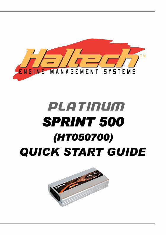
PLATINUM SPRINT 500
(HT050700)
QUICK START GUIDE
LIMITED WARRANTY
Lockin Pty Ltd trading as Haltech warrants the HaltechTM Programmable Fuel Injection System to be free from defects in material or workmanship for a period of 12 months from the date of purchase.
Proof of purchase, in the form of a bill of sale or receipted invoice, which indicates that the product is within the warranty period, must be presented to obtain warranty service. Lockin Pty Ltd trading as Haltech suggests that the purchaser retain the dealer’s dated bill of sale as evidence of the date of retail purchase.
If the HaltechTM Programmable Fuel Injection System is found to be defective as mentioned above, it will be replaced or repaired if returned prepaid along with proof of purchase. This shall constitute the sole liability of Lockin Pty Ltd trading as Haltech.
To the extent permitted by law, the foregoing is exclusive and in lieu of all other warranties or representations, either expressed or implied, including any implied warranty of merchantability or fitness. In no event shall Lockin Pty Ltd trading as Haltech, be liable for special or consequential damages.
IGNITION WIRING WARNING
This system is capable of controlling either Auto-Dwell (also known as intelligent or smart ignitors) which have in-built dwell control or ECU Dwell ignitors (also known as dumb ignitors or Constant Charge Ignitors), which contain no such control. This allows standard ignitors to be used in many cases.
Auto-dwell ignitors are commonly found on early EFI engines with electronic ignition.ECU-dwell ignitors are commonly found in modern ECU controlled ignition systems.
Most standard ignitors are ECU Dwell.It is very important to set the system up to match the type of ignitor used!.In the ignition set-up page the setting should be:To control Auto-dwell ignitors set up as “Constant Duty”To control ECU-dwell ignitors set up as “Constant Charge”If the wrong setting is applied, damage to the ignition system may occur.Burning out ignitors due to wrong set-up will not be regarded as Warranty!Please ensure all power supplies are disconnected before commencing any wiring.
Failure to follow all the warnings and precautions in this manual can lead to damage to engine components and may possibly void your warranty. Incorrect setup of the ECU can also lead to damaged engine components.
Damaged components due to incorrect setup will not be regarded as warranty repairs.
GENERAL INSTALLATION WARNING
Avoid open sparks, flames or operation of electrical devices near flammable substances. Always disconnect the battery cables when doing electrical work on your vehicle.
Do not charge the battery with a 24 Volt truck charger or reverse the polarity of the battery or any charging unit. Do not charge the battery with the engine running as this could expose the ECU to an unregulated power supply that could destroy the ECU and other electrical equipment.
All fuel system components and wiring should be mounted away from heat sources, shielded if necessary and well ventilated. Disconnect the Haltech ECU from the electrical system whenever doing any arc welding on the vehicle by unplugging the wiring harness connector from the ECU.
After completing the installation, make sure that there are no fuel leaks, and no wiring left un-insulated in case a spark or short-circuit occurs and causes a fire. Also make sure that you follow all proper workshop safety procedures. If you're working underneath a jacked-up car, always use safety stands!
AppendixPLATINUM SPRINT 500
Quick Start GuideCongratulations on purchasing a Haltech Engine Management System. This fully programmable product opens the door to virtually limitless performancemodification and tuning of your vehicle. Programmable systems allow you to extract all the performance from your engine by delivering precisely the required amount of fuel and ignition timing that your engine requires for maximum output under all operating conditions.
This quick start guide will walk you through installation of a Haltech ECU into avehicle. This guide is accompanied by the full service manual located on thesoftware CD provided with the ECU that you or your tuner will need to refer tobefore completing your installation and configuration. The Manual can also bedownloaded from the Haltech website www.haltech.com
Installation
Air Temperature Sensor
The sensor should be mounted to provide the best representation of the actualtemperature of the air entering the combustion chamber, i.e. after any turbo orsupercharger, and intercooler, the optimum position being the intake pipe before the throttle. The sensor needs to be in the moving air stream to give fast response times and reduce heat soak effects.The air temp sensor plug is labeled with the letters A and B and should be wired with the signal wire (Grey) to pin B and signal ground wire (Black/White) to pin A
Figure 1– Air Temperature Sensor and Terminations
PLATIN
UM
SPR
INT 5
00
REC
OM
MEN
DED
PO
WER
RELAY
CO
NFIG
UR
ATIO
N
[B] A
VSS
0.5
0
[R] A
VSS
0.5
0
[R/L
] AV
SS 1
.25
TO
EC
U P
IN 1
1
TO
IN
JEC
TO
RS
SW
ITC
HED
+12V S
UPPLY
FRO
M IG
NIT
ION
SW
ITC
H
30
87
87
85
86
EC
U P
OW
ER
RE
LAY
30
87
87
85
86
FU
EL P
UM
P R
ELAY
30
87
87
85
86
IGN
ITIO
N P
OW
ER
RELAY
[B/Y
] AVS
S 0.
50
[B] A
VSS
0.5
0
[R/W
] AVS
S 0
.50
[P] A
VSS
0.5
0
[P] A
VSS
0.5
0
[P] A
VSS
0.50
20A
15A
10A
20A
[R] A
VSS
1.25
[R] A
VSS
1.25
TO
BATTERY
PO
SIT
IVE +
30
87
87
85
86
INJEC
TIO
N P
OW
ER
RELAY
[P] A
VSS
0.5
0
TO
EC
U P
IN 1
0
[B] A
VSS
0.5
0
[R/Y
] AVS
S 1
.25
TO
IG
NIT
ION
CO
ILS
TO
EC
U P
IN 1
2
[O/L
] AVS
S 1.
25TO
PO
SIT
IVE S
IDE O
F F
UEL P
UM
P
[R]A
VSS
1.2
5
[O/G
Y]A
VSS
1.25
[R/Y
]AVS
S 1.
25
[R/W
] AV
SS 0
.50
TO
EC
U P
IN 2
3
TO
CH
ASSIS
GR
OU
ND
[B] A
VSS
2.0
0FU
SE B
LO
CK
CO
NN
EC
TO
R
PAC
KA
RD: 1200 4
943
[B] A
VSS
0.50
N
OT
ES
BO
SCH
RELAY
P/N
: 332 0
19 1
50
OR
EQ
UIV
ALEN
T M
UST B
E U
SED
WIR
ING
NO
TES:
1. M
AIN
WIR
E C
OLO
UR L
ISTE
D F
IRST
E
.G.
RED
/GR
N IN
DIC
ATES
RED
WIR
E W
ITH
GR
EEN
STR
IPE
2. U
SE V
-90
HT
PVC
INSU
LATI
ON.
3. W
IRE
SIZE
S AR
E SH
OW
N IN
AVS
S (s
q.m
m)
[R] A
VSS
1.25
[R/W
] AV
SS 1
.25
HALTECH, SYDNEY AUSTRALIA
DATE: 5TH NOVEMBER 2010
SHEET 2 OF 2
REV F
PLATINUM SPRINT 500 WIRING
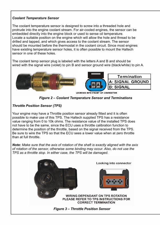
Coolant Temperature Sensor
The coolant temperature sensor is designed to screw into a threaded hole andprotrude into the engine coolant stream. For air-cooled engines, the sensor can beembedded directly into the engine block or used to sense oil temperature.Locate a suitable position on the engine which will allow the hole and thread to bedrilled and tapped, and which gives access to the coolant stream. The sensorshould be mounted before the thermostat in the coolant circuit. Since most engineshave existing temperature sensor holes, it is often possible to mount the Haltechsensor in one of these holes.
The coolant temp sensor plug is labeled with the letters A and B and should bewired with the signal wire (violet) to pin B and sensor ground wire (black/white) to pin A.
Figure 2 – Coolant Temperature Sensor and Terminations Throttle Position Sensor (TPS)
Your engine may have a Throttle position sensor already fitted and it is oftenpossible to make use of this TPS. The Haltech supplied TPS has a resistancevalue ranging from 0 to 10k ohms. The resistance value of the installed TPS doesnot have to be the same, since the ECU uses a throttle calibration function todetermine the position of the throttle, based on the signal received from the TPS.Be sure to wire the TPS so that the ECU sees a lower value when at zero throttlethan at full throttle.
Note: Make sure that the axis of rotation of the shaft is exactly aligned with the axisof rotation of the sensor, otherwise some binding may occur. Also, do not use theTPS as a throttle stop. In either case, the TPS will be damaged.
Figure 3 – Throttle Position Sensor
Optional Haltech Ballast Resistor Wiring
Notes
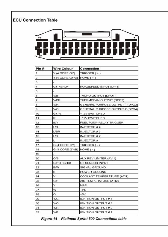
ECU Connection Table
Figure 14 – Platinum Sprint 500 Connections table
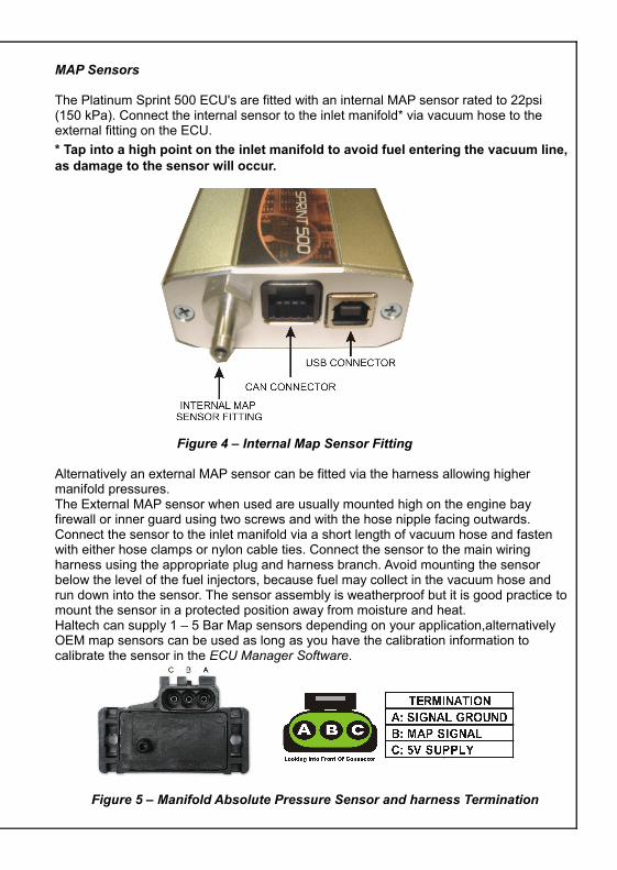
MAP Sensors
The Platinum Sprint 500 ECU's are fitted with an internal MAP sensor rated to 22psi (150 kPa). Connect the internal sensor to the inlet manifold* via vacuum hose to the external fitting on the ECU.* Tap into a high point on the inlet manifold to avoid fuel entering the vacuum line, as damage to the sensor will occur.
Figure 4 – Internal Map Sensor Fitting
Alternatively an external MAP sensor can be fitted via the harness allowing higher manifold pressures. The External MAP sensor when used are usually mounted high on the engine bay firewall or inner guard using two screws and with the hose nipple facing outwards. Connect the sensor to the inlet manifold via a short length of vacuum hose and fasten with either hose clamps or nylon cable ties. Connect the sensor to the main wiring harness using the appropriate plug and harness branch. Avoid mounting the sensor below the level of the fuel injectors, because fuel may collect in the vacuum hose and run down into the sensor. The sensor assembly is weatherproof but it is good practice to mount the sensor in a protected position away from moisture and heat.Haltech can supply 1 – 5 Bar Map sensors depending on your application,alternatively OEM map sensors can be used as long as you have the calibration information to calibrate the sensor in the ECU Manager Software.
Figure 5 – Manifold Absolute Pressure Sensor and harness Termination
Pin # Wire Colour Connection1 Y (4 CORE GY) TRIGGER ( + )
2 Y (4 CORE GY/B) HOME ( + )
3 -
4 GY <SHD> ROADSPEED INPUT (DPI1)
5 -
6 V/B TACHO OUTPUT (DPO1)
7 V/BR THERMOFAN OUTPUT (DPO2)
8 V/R GENERAL PURPOSE OUTPUT 1 (DPO3)
9 V/O GENERAL PURPOSE OUTPUT 2 (DPO4)
10 GY/R +12V SWITCHED
11 R +12V SWITCHED
12 B/Y FUEL PUMP RELAY TRIGGER
13 L/R INJECTOR # 4
14 L/BR INJECTOR # 3
15 L/B INJECTOR # 2
16 L INJECTOR # 1
17 G (4 CORE GY) TRIGGER ( - )
18 G (4 CORE GY/B) HOME ( - )
19 -
20 O/B AUX REV LIMITER (AVI1)
21 GY/O <SHD> O2 SENSOR INPUT
22 B/W SIGNAL GROUND
23 B POWER GROUND
24 V COOLANT TEMPERATURE (ATI1)
25 GY AIR TEMPERATURE (ATI2)
26 Y MAP
27 W TPS
28 O +5V
29 Y/G IGNITION OUTPUT # 4
30 Y/O IGNITION OUTPUT # 3
31 Y/R IGNITION OUTPUT # 2
32 Y/B IGNITION OUTPUT # 1
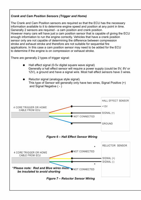
Crank and Cam Position Sensors (Trigger and Home)
The Crank and Cam Position sensors are required so that the ECU has the necessary information available to it to determine engine speed and position at any point in time.Generally 2 sensors are required - a cam position and crank position. However many cars will have just a cam position sensor that is capable of giving the ECU enough information to run the engine correctly. Vehicles that have a crank positionsensor only are not capable of determining the difference between compressionstroke and exhaust stroke and therefore are not suitable for sequential fireapplications. In this case a cam position sensor may need to be added for the ECU to determine if the engine is on compression or exhaust stroke.
There are generally 2 types of trigger signal:
● Hall effect signal (0-5v digital square wave signal) Generally a hall effect sensor will require a power supply (could be 5V, 8V or 12V), a ground and have a signal wire. Most hall effect sensors have 3 wires.
● Reluctor signal (analogue style signal).This type of Sensor will generally only have two wires, Signal Positive (+) and Signal Negative ( - )
Figure 6 – Hall Effect Sensor Wiring
*
* *Please note: Red and Blue wires must be insulated to avoid shorting
Figure 7 – Reluctor Sensor Wiring
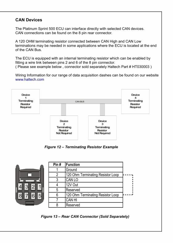
CAN Devices
The Platinum Sprint 500 ECU can interface directly with selected CAN devices.CAN connections can be found on the 8 pin rear connector.
A 120 OHM terminating resistor connected between CAN High and CAN Low terminations may be needed in some applications where the ECU is located at the end of the CAN Bus.
The ECU is equipped with an internal terminating resistor which can be enabled by fitting a wire link between pins 2 and 6 of the 8 pin connector.( Please see example below , connector sold separately Haltech Part # HT030003 )
Wiring Information for our range of data acquisition dashes can be found on our websitewww.haltech.com
Figure 12 – Terminating Resistor Example
Figure 13 – Rear CAN Connector (Sold Separately)
HALL EFFECT SENSOR
+12V
SIGNAL (+)
GROUND
NOT CONNECTED
4 CORE TRIGGER OR HOM E CABLE FROM ECU
RELUCTOR SENSOR
SIGNAL (+)
NOT CONNECTED4 CORE TRIGGER OR HOM E CABLE FROM ECU
SIGNAL (-)
NOT CONNECTED
1234
5678
Device1
TerminatingResistor Required
Device2
TerminatingResistor
Not Required
Device3
TerminatingResistor
Not Required
Device4
TerminatingResistor Required
CAN BUS
Pin # Function1 Ground2 120 Ohm Terminating Resistor Loop3 CAN LO4 12V Out5 Reserved6 120 Ohm Terminating Resistor Loop7 CAN HI8 Reserved
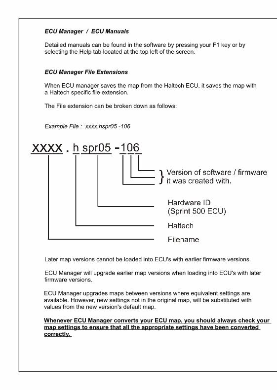
ECU Manager / ECU Manuals
Detailed manuals can be found in the software by pressing your F1 key or byselecting the Help tab located at the top left of the screen.
ECU Manager File Extensions
When ECU manager saves the map from the Haltech ECU, it saves the map witha Haltech specific file extension.
The File extension can be broken down as follows:
Example File : xxxx.hspr05 -106
Later map versions cannot be loaded into ECU's with earlier firmware versions.
ECU Manager will upgrade earlier map versions when loading into ECU's with later firmware versions.
ECU Manager upgrades maps between versions where equivalent settings are available. However, new settings not in the original map, will be substituted with values from the new version's default map.
Whenever ECU Manager converts your ECU map, you should always check your map settings to ensure that all the appropriate settings have been converted correctly.
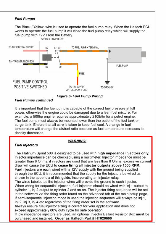
Fuel Pumps
The Black / Yellow wire is used to operate the fuel pump relay. When the Haltech ECUwants to operate the fuel pump it will close the fuel pump relay which will supply the fuel pump with 12V From the Battery.
Figure 8- Fuel Pump WiringFuel Pumps continued
It is important that the fuel pump is capable of the correct fuel pressure at fullpower, otherwise the engine could be damaged due to a lean fuel mixture. Forexample, a 500hp engine requires approximately 210lb/hr for a petrol engine.The fuel pump must always be mounted lower than the outlet of the fuel tank orsurge tank. Ensure that all care is taken to keep fuel cool. A change in fueltemperature will change the air/fuel ratio because as fuel temperature increases itsdensity decreases.
WARNING!Fuel Injectors
The Platinum Sprint 500 is designed to be used with high impedance injectors only.Injector impedance can be checked using a multimeter. Injector impedance must be
greater than 8 Ohms, if injectors are used that are less than 8 Ohms, excessive current draw will cause the ECU to cease firing all injector outputs above 1500 RPM.Fuel injectors are each wired with a 12V supply with the ground being suppliedthrough the ECU, it is recommended that the supply for the Injectors be wired asshown in the appendix of this guide, incorporating an injector relay.The wires labeled as the injector wires will provide the ground to each injector. When wiring for sequential injection, fuel injectors should be wired with inj 1 output to cylinder 1, inj 2 output to cylinder 2 and so on. The injector firing sequence will be set in the software via the firing order found on the advanced tab of the main setup page. If semi-sequential injection mode is used the injection sequence will always be inj 1, Inj 2, inj 3, inj 4 etc regardless of the firing order set in the software.Always ensure fuel injector sizing is correct for your application and does notexceed approximately 80% duty cycle for safe operation.If low impedance injectors are used, an optional Injector Ballast Resistor Box must be purchased and installed. Order as Haltech Part # HT020600
85 87 87
86 30
TO 12V IGNITION SUPPLY
TO - TRIGGER FROM ECU
TO FUEL PUMP + TERMINAL
TO 12V SUPPLY
FUEL PUMP
+_
TO GROUND VIA FUEL PUMP FUSE
FUSE
POSITIVE SWITCHED FUEL PUMP CONTROL
12V FUEL PUMP RELAY
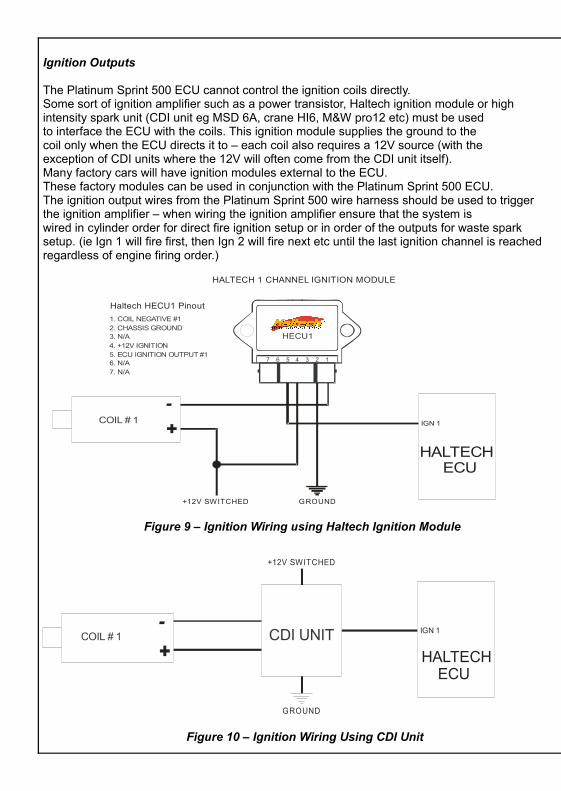
Ignition Outputs
The Platinum Sprint 500 ECU cannot control the ignition coils directly.Some sort of ignition amplifier such as a power transistor, Haltech ignition module or highintensity spark unit (CDI unit eg MSD 6A, crane HI6, M&W pro12 etc) must be usedto interface the ECU with the coils. This ignition module supplies the ground to thecoil only when the ECU directs it to – each coil also requires a 12V source (with theexception of CDI units where the 12V will often come from the CDI unit itself).Many factory cars will have ignition modules external to the ECU. These factory modules can be used in conjunction with the Platinum Sprint 500 ECU.The ignition output wires from the Platinum Sprint 500 wire harness should be used to triggerthe ignition amplifier – when wiring the ignition amplifier ensure that the system iswired in cylinder order for direct fire ignition setup or in order of the outputs for waste spark setup. (ie Ign 1 will fire first, then Ign 2 will fire next etc until the last ignition channel is reached regardless of engine firing order.)
Figure 9 – Ignition Wiring using Haltech Ignition Module
Figure 10 – Ignition Wiring Using CDI Unit
Startup
With the settings now calibrated with correct fuel setup, ignition setup and triggersetup, go to the Main setup menu and calibrate the throttle
Check to ensure that the fuel and ignition maps all have sensible values in them.
Check that all sensors are reading correctly by going to the engine data page andviewing their values. Ensure the throttle reads smoothly from 0-100% in its fullrange of movement. The MAP sensor should read atmospheric pressurewhen the engine is stopped.
Power up the fuel pumps and check entire fuel system for leaks before attemptingto start the engine.
Once verified that all sensors are correctly operating and fuel system is functional,attempt to start the engine. If engine does not start check:
1. Ignition Timing
2. Correct Fuel Pressure
3. Spark Plugs are not fouled or wet
4. Engine Compression
5. Ignition is wired in correct firing order
6. Ignition is firing on intake stroke not exhaust stroke
Once engine is running, ensure fuel pressure remains correct under all conditions and that battery is charging.
1. COIL NEGATIVE #12. CHASSIS GROUND3. N/A4. +12V IGNITION5. ECU IGNITION OUTPUT #16. N/A7. N/A
HALTECHHECU1
7 6 5 4 3 2 1
+
-
+12V SWITCHED GROUND
Haltech HECU1 Pinout
HALTECH 1 CHANNEL IGNITION MODULE
HALTECH ECU
IGN 1COIL # 1
+
-
+12V SWITCHED
GROUND
HALTECH ECU
IGN 1COIL # 1 CDI UNIT
Initial Software Setup
Main Setup (Basic) Page
Set the basic engine parameters in the main setup page, number of cylinders, firing order, load source and map source (enable or disable the use of the internal map sensor)
Trigger Setup Page
Set the crank and cam (trigger and home) angle sensor type and description in the Trigger setup page. If using a hall effect or optical style crank sensor then set trigger type to hall effect.In most stand alone applications the trigger pullup will need to be set to ON whenusing a hall effect crank sensor. In a piggy back application the pullup will be set tooff. Trigger pullup will be set to off for all reluctor (sine wave) style trigger inputs.
Ignition Setup Page
Setting the base timing needs to be done with the ignition setup page open. Basetiming is the process of synchronising the ECU’s operations with the engines.This needs to be calibrated so that the ECU knows the crankshaft position at any point intime. This is required for accurate fuel delivery and spark timing.First, go to the fuel setup page and disable the fuel injectors (at this stage it is notdesired that the engine attempts to start). To reduce stress on the starter motor it is alsoadvisable to remove the spark plugs to help the engine crank more freely whensetting base timing.Set lock timing to ON and lock timing angle to 10 degrees. Crank engine, using atiming light connected to ignition lead for number 1 cylinder. Adjust the tooth offsetand trigger angle until timing reads 10 degrees as viewed with a timing light oncrank pulley. Tooth offset gives large changes to timing, trigger angle is used to finetune timing to exactly 10 degrees (any angle can be set as the lock timing angle; inthis example 10 degrees was used). It is however possible to set the lock timing tozero degrees (or any other positive number) and adjust tooth offset and triggerangle until the crank pulley shows this value when viewed with a timing light.If there is no RPM being displayed in the software check for correct trigger setup, correct sensor wiring, correct trigger type, pull ups enabled / disabled, trigger edge falling / rising.
Fuel Setup Page
Set the basic fuel parameters, injection mode, fuel pump prime time and ensure that the fuel injectors are enabled in this setup page once ignition timing has been checked.
Digital Pulsed Outputs (DPO)
The Platinum Sprint 500 ECU has 4 digital outputs. The first two outputs are preset to the Tacho and Thermofan functions and the remaining two outputs are user configurable.
Digital Pulsed outputs are capable of outputting pulsed waveforms with varying duty and frequency. DPO's can be used to control various devices such as thermo fans, shift lights, water injection solenoids ,intercooler fans etc. When a Digital Pulsed output is activated by the ECU the output will switch to ground. Solenoid valves and shift lights etc can be run directly from the output, however high current devices such as thermo fans and additional fuel pumps must be activated through a relay. This way the DPO is only switching a relay and not a high current draw device.Digital Pulsed Outputs are limited to 800mA Max current draw.
Digital Pulsed Inputs (DPI)
Digital Pulsed Inputs are capable of accepting pulsed input information such as for a road speed sensor. These inputs measure the time periods between the pulses and can process this information to provide quantities such as road speed.
High Tension Leads (spark plug leads) / Capacitive Discharge Ignition Units (CDI )
High tension leads and CDI units can cause significant noise or interference on the ECU wiring. Keep all ignition wires a minimum of 100mm from any other wires and ECU components. If ignition wires must be crossed, ensure wires cross ignition leads at right angles. Keep power and grounding points separate to those used for ECU.
Wire connections
When using crimp connectors ensure that the correct crimping tool is used – if indoubt do a pull test on a crimp connector, the wire should break before the wirepulls out of the crimp. Terminal soldering can weaken a connection and should onlybe used as a last resort. If solder joints are used, ensure joints are well isolatedfrom movement as solder joints are prone to fracture.When splicing 2 wires it is preferable to use a crimp splice – again if using a solderjoint, ensure joint is limited in its range of possible movement as solder joints areprone to fracture. Always use heatshrink sleeving to insulate wires and provide
Powering up the ECU
The Platinum Sprint 500 requires 12VDC to operate. Please connect both the Red and Red/White cables to a switched +12VDC supply within the vehicle. This is best achieved on a vehicle with an existing wiring harness by wiring both these inputs to the output of the Engine Control Relay via an inline 10A fuse. Please do not connect these cables directly to the ignition switch, as it will not be able to handle the current required to operate the ECU. Please refer to the wiring diagrams contained within this quick start guide for a recommended power relay setup on an unwired vehicle.
To avoid damage to ignition components, never connect the ignition modules to the ECU until the ECU is configured. The same applies to the fuel system, never connect fuel injectors until the ECU is configured, otherwise the engine may flood with fuel.
Grounding
One of the most common wiring problems experienced is poor grounding. There should be no paint, anodizing or other surface layer protection between the ground wire and engine block or chassis. Temporary wiring will almost certainly cause a problem, use a proper ground eyelet terminal and do not use loctite or similar locking agents as they may become insulators preventing good earth connection.
ECU Ground (Black) should be connected to the chassis of the vehicle, and Signal Ground (Black / White) should be connected directly to the Battery negative terminal.
Please make sure your Engine block has a ground strap to the chassis.
Figure 11 – Main Power Wiring
ECU Manager Software
ECU Manager software is used for setup, calibration and diagnostics and canbe found on the CD supplied with this unit or downloaded from the Haltech website www.haltech.com
Minimum System Requirements
Operating System: Windows 2000 SP4 / XP / Vista / Windows 7Processor Speed: 1GHzRAM: 256 MbVideo Card: 128MB graphics card with 3D accelerationUSB: 1.1Hard Drive Space: 250MbMinimum Screen Resolution: 1024 x 768 pixels
Installing ECU Manager
Installing ECU Manager onto your PC is performed similar to any other Windows software package. Installation is outlined below to ensure correct installation:
1.Insert the CD-ROM into your PC’s CD-ROM drive. The CD should automatically launch into the Haltech Browser. If the CD does not run automatically double click on the “My Computer” icon on the desktop, double click on the Haltech icon (CD- ROM drive) to start the browser software.
2.The Browser will display the disclaimer and you will need to agree to the terms stated before allowing to progress. Read the Disclaimer and click on AGREE if you agree.
3.Now you will be able to access all the information contained on the CD
4.To download the Platinum Software, click on the Platinum Series ECU Manager Link. You will be prompted to install the software. Click “Install” to install ECU Manager and the Data Log viewer.
5. Follow the software prompts and install the software.
With your programming cable (USB) attached to your ECU and the other endconnected to your laptop, power up the ECU by turning your key to IGN. Start theprogramming software on your PC and go online with the ECU.
Initial Software Setup
Main Setup (Basic) Page
Set the basic engine parameters in the main setup page, number of cylinders, firing order, load source and map source (enable or disable the use of the internal map sensor)
Trigger Setup Page
Set the crank and cam (trigger and home) angle sensor type and description in the Trigger setup page. If using a hall effect or optical style crank sensor then set trigger type to hall effect.In most stand alone applications the trigger pullup will need to be set to ON whenusing a hall effect crank sensor. In a piggy back application the pullup will be set tooff. Trigger pullup will be set to off for all reluctor (sine wave) style trigger inputs.
Ignition Setup Page
Setting the base timing needs to be done with the ignition setup page open. Basetiming is the process of synchronising the ECU’s operations with the engines.This needs to be calibrated so that the ECU knows the crankshaft position at any point intime. This is required for accurate fuel delivery and spark timing.First, go to the fuel setup page and disable the fuel injectors (at this stage it is notdesired that the engine attempts to start). To reduce stress on the starter motor it is alsoadvisable to remove the spark plugs to help the engine crank more freely whensetting base timing.Set lock timing to ON and lock timing angle to 10 degrees. Crank engine, using atiming light connected to ignition lead for number 1 cylinder. Adjust the tooth offsetand trigger angle until timing reads 10 degrees as viewed with a timing light oncrank pulley. Tooth offset gives large changes to timing, trigger angle is used to finetune timing to exactly 10 degrees (any angle can be set as the lock timing angle; inthis example 10 degrees was used). It is however possible to set the lock timing tozero degrees (or any other positive number) and adjust tooth offset and triggerangle until the crank pulley shows this value when viewed with a timing light.If there is no RPM being displayed in the software check for correct trigger setup, correct sensor wiring, correct trigger type, pull ups enabled / disabled, trigger edge falling / rising.
Fuel Setup Page
Set the basic fuel parameters, injection mode, fuel pump prime time and ensure that the fuel injectors are enabled in this setup page once ignition timing has been checked.
Digital Pulsed Outputs (DPO)
The Platinum Sprint 500 ECU has 4 digital outputs. The first two outputs are preset to the Tacho and Thermofan functions and the remaining two outputs are user configurable.
Digital Pulsed outputs are capable of outputting pulsed waveforms with varying duty and frequency. DPO's can be used to control various devices such as thermo fans, shift lights, water injection solenoids ,intercooler fans etc. When a Digital Pulsed output is activated by the ECU the output will switch to ground. Solenoid valves and shift lights etc can be run directly from the output, however high current devices such as thermo fans and additional fuel pumps must be activated through a relay. This way the DPO is only switching a relay and not a high current draw device.Digital Pulsed Outputs are limited to 800mA Max current draw.
Digital Pulsed Inputs (DPI)
Digital Pulsed Inputs are capable of accepting pulsed input information such as for a road speed sensor. These inputs measure the time periods between the pulses and can process this information to provide quantities such as road speed.
High Tension Leads (spark plug leads) / Capacitive Discharge Ignition Units (CDI )
High tension leads and CDI units can cause significant noise or interference on the ECU wiring. Keep all ignition wires a minimum of 100mm from any other wires and ECU components. If ignition wires must be crossed, ensure wires cross ignition leads at right angles. Keep power and grounding points separate to those used for ECU.
Wire connections
When using crimp connectors ensure that the correct crimping tool is used – if indoubt do a pull test on a crimp connector, the wire should break before the wirepulls out of the crimp. Terminal soldering can weaken a connection and should onlybe used as a last resort. If solder joints are used, ensure joints are well isolatedfrom movement as solder joints are prone to fracture.When splicing 2 wires it is preferable to use a crimp splice – again if using a solderjoint, ensure joint is limited in its range of possible movement as solder joints areprone to fracture. Always use heatshrink sleeving to insulate wires and provide
Ignition Outputs
The Platinum Sprint 500 ECU cannot control the ignition coils directly.Some sort of ignition amplifier such as a power transistor, Haltech ignition module or highintensity spark unit (CDI unit eg MSD 6A, crane HI6, M&W pro12 etc) must be usedto interface the ECU with the coils. This ignition module supplies the ground to thecoil only when the ECU directs it to – each coil also requires a 12V source (with theexception of CDI units where the 12V will often come from the CDI unit itself).Many factory cars will have ignition modules external to the ECU. These factory modules can be used in conjunction with the Platinum Sprint 500 ECU.The ignition output wires from the Platinum Sprint 500 wire harness should be used to triggerthe ignition amplifier – when wiring the ignition amplifier ensure that the system iswired in cylinder order for direct fire ignition setup or in order of the outputs for waste spark setup. (ie Ign 1 will fire first, then Ign 2 will fire next etc until the last ignition channel is reached regardless of engine firing order.)
Figure 9 – Ignition Wiring using Haltech Ignition Module
Figure 10 – Ignition Wiring Using CDI Unit
Startup
With the settings now calibrated with correct fuel setup, ignition setup and triggersetup, go to the Main setup menu and calibrate the throttle
Check to ensure that the fuel and ignition maps all have sensible values in them.
Check that all sensors are reading correctly by going to the engine data page andviewing their values. Ensure the throttle reads smoothly from 0-100% in its fullrange of movement. The MAP sensor should read atmospheric pressurewhen the engine is stopped.
Power up the fuel pumps and check entire fuel system for leaks before attemptingto start the engine.
Once verified that all sensors are correctly operating and fuel system is functional,attempt to start the engine. If engine does not start check:
1. Ignition Timing
2. Correct Fuel Pressure
3. Spark Plugs are not fouled or wet
4. Engine Compression
5. Ignition is wired in correct firing order
6. Ignition is firing on intake stroke not exhaust stroke
Once engine is running, ensure fuel pressure remains correct under all conditions and that battery is charging.
1. COIL NEGATIVE #12. CHASSIS GROUND3. N/A4. +12V IGNITION5. ECU IGNITION OUTPUT #16. N/A7. N/A
HALTECHHECU1
7 6 5 4 3 2 1
+
-
+12V SWITCHED GROUND
Haltech HECU1 Pinout
HALTECH 1 CHANNEL IGNITION MODULE
HALTECH ECU
IGN 1COIL # 1
+
-
+12V SWITCHED
GROUND
HALTECH ECU
IGN 1COIL # 1 CDI UNIT
ECU Manager / ECU Manuals
Detailed manuals can be found in the software by pressing your F1 key or byselecting the Help tab located at the top left of the screen.
ECU Manager File Extensions
When ECU manager saves the map from the Haltech ECU, it saves the map witha Haltech specific file extension.
The File extension can be broken down as follows:
Example File : xxxx.hspr05 -106
Later map versions cannot be loaded into ECU's with earlier firmware versions.
ECU Manager will upgrade earlier map versions when loading into ECU's with later firmware versions.
ECU Manager upgrades maps between versions where equivalent settings are available. However, new settings not in the original map, will be substituted with values from the new version's default map.
Whenever ECU Manager converts your ECU map, you should always check your map settings to ensure that all the appropriate settings have been converted correctly.
Fuel Pumps
The Black / Yellow wire is used to operate the fuel pump relay. When the Haltech ECUwants to operate the fuel pump it will close the fuel pump relay which will supply the fuel pump with 12V From the Battery.
Figure 8- Fuel Pump WiringFuel Pumps continued
It is important that the fuel pump is capable of the correct fuel pressure at fullpower, otherwise the engine could be damaged due to a lean fuel mixture. Forexample, a 500hp engine requires approximately 210lb/hr for a petrol engine.The fuel pump must always be mounted lower than the outlet of the fuel tank orsurge tank. Ensure that all care is taken to keep fuel cool. A change in fueltemperature will change the air/fuel ratio because as fuel temperature increases itsdensity decreases.
WARNING!Fuel Injectors
The Platinum Sprint 500 is designed to be used with high impedance injectors only.Injector impedance can be checked using a multimeter. Injector impedance must be
greater than 8 Ohms, if injectors are used that are less than 8 Ohms, excessive current draw will cause the ECU to cease firing all injector outputs above 1500 RPM.Fuel injectors are each wired with a 12V supply with the ground being suppliedthrough the ECU, it is recommended that the supply for the Injectors be wired asshown in the appendix of this guide, incorporating an injector relay.The wires labeled as the injector wires will provide the ground to each injector. When wiring for sequential injection, fuel injectors should be wired with inj 1 output to cylinder 1, inj 2 output to cylinder 2 and so on. The injector firing sequence will be set in the software via the firing order found on the advanced tab of the main setup page. If semi-sequential injection mode is used the injection sequence will always be inj 1, Inj 2, inj 3, inj 4 etc regardless of the firing order set in the software.Always ensure fuel injector sizing is correct for your application and does notexceed approximately 80% duty cycle for safe operation.If low impedance injectors are used, an optional Injector Ballast Resistor Box must be purchased and installed. Order as Haltech Part # HT020600
85 87 87
86 30
TO 12V IGNITION SUPPLY
TO - TRIGGER FROM ECU
TO FUEL PUMP + TERMINAL
TO 12V SUPPLY
FUEL PUMP
+_
TO GROUND VIA FUEL PUMP FUSE
FUSE
POSITIVE SWITCHED FUEL PUMP CONTROL
12V FUEL PUMP RELAY
Crank and Cam Position Sensors (Trigger and Home)
The Crank and Cam Position sensors are required so that the ECU has the necessary information available to it to determine engine speed and position at any point in time.Generally 2 sensors are required - a cam position and crank position. However many cars will have just a cam position sensor that is capable of giving the ECU enough information to run the engine correctly. Vehicles that have a crank positionsensor only are not capable of determining the difference between compressionstroke and exhaust stroke and therefore are not suitable for sequential fireapplications. In this case a cam position sensor may need to be added for the ECU to determine if the engine is on compression or exhaust stroke.
There are generally 2 types of trigger signal:
● Hall effect signal (0-5v digital square wave signal) Generally a hall effect sensor will require a power supply (could be 5V, 8V or 12V), a ground and have a signal wire. Most hall effect sensors have 3 wires.
● Reluctor signal (analogue style signal).This type of Sensor will generally only have two wires, Signal Positive (+) and Signal Negative ( - )
Figure 6 – Hall Effect Sensor Wiring
*
* *Please note: Red and Blue wires must be insulated to avoid shorting
Figure 7 – Reluctor Sensor Wiring
CAN Devices
The Platinum Sprint 500 ECU can interface directly with selected CAN devices.CAN connections can be found on the 8 pin rear connector.
A 120 OHM terminating resistor connected between CAN High and CAN Low terminations may be needed in some applications where the ECU is located at the end of the CAN Bus.
The ECU is equipped with an internal terminating resistor which can be enabled by fitting a wire link between pins 2 and 6 of the 8 pin connector.( Please see example below , connector sold separately Haltech Part # HT030003 )
Wiring Information for our range of data acquisition dashes can be found on our websitewww.haltech.com
Figure 12 – Terminating Resistor Example
Figure 13 – Rear CAN Connector (Sold Separately)
HALL EFFECT SENSOR
+12V
SIGNAL (+)
GROUND
NOT CONNECTED
4 CORE TRIGGER OR HOM E CABLE FROM ECU
RELUCTOR SENSOR
SIGNAL (+)
NOT CONNECTED4 CORE TRIGGER OR HOM E CABLE FROM ECU
SIGNAL (-)
NOT CONNECTED
1234
5678
Device1
TerminatingResistor Required
Device2
TerminatingResistor
Not Required
Device3
TerminatingResistor
Not Required
Device4
TerminatingResistor Required
CAN BUS
Pin # Function1 Ground2 120 Ohm Terminating Resistor Loop3 CAN LO4 12V Out5 Reserved6 120 Ohm Terminating Resistor Loop7 CAN HI8 Reserved
ECU Connection Table
Figure 14 – Platinum Sprint 500 Connections table
MAP Sensors
The Platinum Sprint 500 ECU's are fitted with an internal MAP sensor rated to 22psi (150 kPa). Connect the internal sensor to the inlet manifold* via vacuum hose to the external fitting on the ECU.* Tap into a high point on the inlet manifold to avoid fuel entering the vacuum line, as damage to the sensor will occur.
Figure 4 – Internal Map Sensor Fitting
Alternatively an external MAP sensor can be fitted via the harness allowing higher manifold pressures. The External MAP sensor when used are usually mounted high on the engine bay firewall or inner guard using two screws and with the hose nipple facing outwards. Connect the sensor to the inlet manifold via a short length of vacuum hose and fasten with either hose clamps or nylon cable ties. Connect the sensor to the main wiring harness using the appropriate plug and harness branch. Avoid mounting the sensor below the level of the fuel injectors, because fuel may collect in the vacuum hose and run down into the sensor. The sensor assembly is weatherproof but it is good practice to mount the sensor in a protected position away from moisture and heat.Haltech can supply 1 – 5 Bar Map sensors depending on your application,alternatively OEM map sensors can be used as long as you have the calibration information to calibrate the sensor in the ECU Manager Software.
Figure 5 – Manifold Absolute Pressure Sensor and harness Termination
Pin # Wire Colour Connection1 Y (4 CORE GY) TRIGGER ( + )
2 Y (4 CORE GY/B) HOME ( + )
3 -
4 GY <SHD> ROADSPEED INPUT (DPI1)
5 -
6 V/B TACHO OUTPUT (DPO1)
7 V/BR THERMOFAN OUTPUT (DPO2)
8 V/R GENERAL PURPOSE OUTPUT 1 (DPO3)
9 V/O GENERAL PURPOSE OUTPUT 2 (DPO4)
10 GY/R +12V SWITCHED
11 R +12V SWITCHED
12 B/Y FUEL PUMP RELAY TRIGGER
13 L/R INJECTOR # 4
14 L/BR INJECTOR # 3
15 L/B INJECTOR # 2
16 L INJECTOR # 1
17 G (4 CORE GY) TRIGGER ( - )
18 G (4 CORE GY/B) HOME ( - )
19 -
20 O/B AUX REV LIMITER (AVI1)
21 GY/O <SHD> O2 SENSOR INPUT
22 B/W SIGNAL GROUND
23 B POWER GROUND
24 V COOLANT TEMPERATURE (ATI1)
25 GY AIR TEMPERATURE (ATI2)
26 Y MAP
27 W TPS
28 O +5V
29 Y/G IGNITION OUTPUT # 4
30 Y/O IGNITION OUTPUT # 3
31 Y/R IGNITION OUTPUT # 2
32 Y/B IGNITION OUTPUT # 1
Coolant Temperature Sensor
The coolant temperature sensor is designed to screw into a threaded hole andprotrude into the engine coolant stream. For air-cooled engines, the sensor can beembedded directly into the engine block or used to sense oil temperature.Locate a suitable position on the engine which will allow the hole and thread to bedrilled and tapped, and which gives access to the coolant stream. The sensorshould be mounted before the thermostat in the coolant circuit. Since most engineshave existing temperature sensor holes, it is often possible to mount the Haltechsensor in one of these holes.
The coolant temp sensor plug is labeled with the letters A and B and should bewired with the signal wire (violet) to pin B and sensor ground wire (black/white) to pin A.
Figure 2 – Coolant Temperature Sensor and Terminations Throttle Position Sensor (TPS)
Your engine may have a Throttle position sensor already fitted and it is oftenpossible to make use of this TPS. The Haltech supplied TPS has a resistancevalue ranging from 0 to 10k ohms. The resistance value of the installed TPS doesnot have to be the same, since the ECU uses a throttle calibration function todetermine the position of the throttle, based on the signal received from the TPS.Be sure to wire the TPS so that the ECU sees a lower value when at zero throttlethan at full throttle.
Note: Make sure that the axis of rotation of the shaft is exactly aligned with the axisof rotation of the sensor, otherwise some binding may occur. Also, do not use theTPS as a throttle stop. In either case, the TPS will be damaged.
Figure 3 – Throttle Position Sensor
Optional Haltech Ballast Resistor Wiring
Notes
AppendixPLATINUM SPRINT 500
Quick Start GuideCongratulations on purchasing a Haltech Engine Management System. This fully programmable product opens the door to virtually limitless performancemodification and tuning of your vehicle. Programmable systems allow you to extract all the performance from your engine by delivering precisely the required amount of fuel and ignition timing that your engine requires for maximum output under all operating conditions.
This quick start guide will walk you through installation of a Haltech ECU into avehicle. This guide is accompanied by the full service manual located on thesoftware CD provided with the ECU that you or your tuner will need to refer tobefore completing your installation and configuration. The Manual can also bedownloaded from the Haltech website www.haltech.com
Installation
Air Temperature Sensor
The sensor should be mounted to provide the best representation of the actualtemperature of the air entering the combustion chamber, i.e. after any turbo orsupercharger, and intercooler, the optimum position being the intake pipe before the throttle. The sensor needs to be in the moving air stream to give fast response times and reduce heat soak effects.The air temp sensor plug is labeled with the letters A and B and should be wired with the signal wire (Grey) to pin B and signal ground wire (Black/White) to pin A
Figure 1– Air Temperature Sensor and Terminations
PLATIN
UM
SPR
INT 5
00
REC
OM
MEN
DED
PO
WER
RELAY
CO
NFIG
UR
ATIO
N
[B] A
VSS
0.5
0
[R] A
VSS
0.5
0
[R/L
] AV
SS 1
.25
TO
EC
U P
IN 1
1
TO
IN
JEC
TO
RS
SW
ITC
HED
+12V S
UPPLY
FRO
M IG
NIT
ION
SW
ITC
H
30
87
87
85
86
EC
U P
OW
ER
RE
LAY
30
87
87
85
86
FU
EL P
UM
P R
ELAY
30
87
87
85
86
IGN
ITIO
N P
OW
ER
RELAY
[B/Y
] AVS
S 0.
50
[B] A
VSS
0.5
0
[R/W
] AVS
S 0
.50
[P] A
VSS
0.5
0
[P] A
VSS
0.5
0
[P] A
VSS
0.50
20A
15A
10A
20A
[R] A
VSS
1.25
[R] A
VSS
1.25
TO
BATTERY
PO
SIT
IVE +
30
87
87
85
86
INJEC
TIO
N P
OW
ER
RELAY
[P] A
VSS
0.5
0
TO
EC
U P
IN 1
0
[B] A
VSS
0.5
0
[R/Y
] AVS
S 1
.25
TO
IG
NIT
ION
CO
ILS
TO
EC
U P
IN 1
2
[O/L
] AVS
S 1.
25TO
PO
SIT
IVE S
IDE O
F F
UEL P
UM
P
[R]A
VSS
1.2
5
[O/G
Y]A
VSS
1.25
[R/Y
]AVS
S 1.
25
[R/W
] AV
SS 0
.50
TO
EC
U P
IN 2
3
TO
CH
ASSIS
GR
OU
ND
[B] A
VSS
2.0
0FU
SE B
LO
CK
CO
NN
EC
TO
R
PAC
KA
RD: 1200 4
943
[B] A
VSS
0.50
N
OT
ES
BO
SCH
RELAY
P/N
: 332 0
19 1
50
OR
EQ
UIV
ALEN
T M
UST B
E U
SED
WIR
ING
NO
TES:
1. M
AIN
WIR
E C
OLO
UR L
ISTE
D F
IRST
E
.G.
RED
/GR
N IN
DIC
ATES
RED
WIR
E W
ITH
GR
EEN
STR
IPE
2. U
SE V
-90
HT
PVC
INSU
LATI
ON.
3. W
IRE
SIZE
S AR
E SH
OW
N IN
AVS
S (s
q.m
m)
[R] A
VSS
1.25
[R/W
] AV
SS 1
.25
HALTECH, SYDNEY AUSTRALIA
DATE: 5TH NOVEMBER 2010
SHEET 2 OF 2
REV F
PLATINUM SPRINT 500 WIRING
LIMITED WARRANTY
Lockin Pty Ltd trading as Haltech warrants the HaltechTM Programmable Fuel Injection System to be free from defects in material or workmanship for a period of 12 months from the date of purchase.
Proof of purchase, in the form of a bill of sale or receipted invoice, which indicates that the product is within the warranty period, must be presented to obtain warranty service. Lockin Pty Ltd trading as Haltech suggests that the purchaser retain the dealer’s dated bill of sale as evidence of the date of retail purchase.
If the HaltechTM Programmable Fuel Injection System is found to be defective as mentioned above, it will be replaced or repaired if returned prepaid along with proof of purchase. This shall constitute the sole liability of Lockin Pty Ltd trading as Haltech.
To the extent permitted by law, the foregoing is exclusive and in lieu of all other warranties or representations, either expressed or implied, including any implied warranty of merchantability or fitness. In no event shall Lockin Pty Ltd trading as Haltech, be liable for special or consequential damages.
IGNITION WIRING WARNING
This system is capable of controlling either Auto-Dwell (also known as intelligent or smart ignitors) which have in-built dwell control or ECU Dwell ignitors (also known as dumb ignitors or Constant Charge Ignitors), which contain no such control. This allows standard ignitors to be used in many cases.
Auto-dwell ignitors are commonly found on early EFI engines with electronic ignition.ECU-dwell ignitors are commonly found in modern ECU controlled ignition systems.
Most standard ignitors are ECU Dwell.It is very important to set the system up to match the type of ignitor used!.In the ignition set-up page the setting should be:To control Auto-dwell ignitors set up as “Constant Duty”To control ECU-dwell ignitors set up as “Constant Charge”If the wrong setting is applied, damage to the ignition system may occur.Burning out ignitors due to wrong set-up will not be regarded as Warranty!Please ensure all power supplies are disconnected before commencing any wiring.
Failure to follow all the warnings and precautions in this manual can lead to damage to engine components and may possibly void your warranty. Incorrect setup of the ECU can also lead to damaged engine components.
Damaged components due to incorrect setup will not be regarded as warranty repairs.
GENERAL INSTALLATION WARNING
Avoid open sparks, flames or operation of electrical devices near flammable substances. Always disconnect the battery cables when doing electrical work on your vehicle.
Do not charge the battery with a 24 Volt truck charger or reverse the polarity of the battery or any charging unit. Do not charge the battery with the engine running as this could expose the ECU to an unregulated power supply that could destroy the ECU and other electrical equipment.
All fuel system components and wiring should be mounted away from heat sources, shielded if necessary and well ventilated. Disconnect the Haltech ECU from the electrical system whenever doing any arc welding on the vehicle by unplugging the wiring harness connector from the ECU.
After completing the installation, make sure that there are no fuel leaks, and no wiring left un-insulated in case a spark or short-circuit occurs and causes a fire. Also make sure that you follow all proper workshop safety procedures. If you're working underneath a jacked-up car, always use safety stands!

HALTECH HEAD OFFICE: PH: +612 9729 0999FAX: +612 9729 0900EMAIL: [email protected]
HALTECH US OFFICE: EMAIL: [email protected]
See the Haltech Website for your local authorized dealer.
www.haltech.com
Version 6
PLATINUM SPRINT 500
(HT050700)
QUICK START GUIDE
![SUPERFLOWER社 80PLUS PLATINUM認証ハイエン … Platinum SE.pdf[release_LEADEX PLATINUM SE] 【SUPERFLOWER社 80PLUS PLATINUM認証ハイエンド1000W電源 「LEADEX PLATINUM](https://img.pdfslide.net/doc/110x75/5f2f89cb73e4b41d036925e4/superflowerc-80plus-platinumeeff-platinum-sepdf-releaseleadex.jpg)