Embed Size (px)
Citation preview
1
Andersen Storm Door Division is a wholly owned subsidiary of Andersen Corporation. Andersen Storm Door Division manufactures and supports the limited warranties for Andersen® and EMCO® storm doors. “Andersen” and “EMCO” and all other marks where denoted are trade-marks of Andersen Corporation. ©2015 Andersen Corporation. All rights reserved.
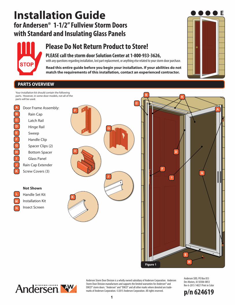
for Andersen® 1-1/2” Fullview Storm Doorswith Standard and Insulating Glass Panels
Installation Guide
Andersen SDD, PO Box 853Des Moines, IA 50306-0853 Rev 6-2015 14021 Print in Color
Door Frame Assembly:
Rain Cap
Latch Rail
Hinge Rail
Sweep
Handle Clip
Spacer Clips (2)
Bottom Spacer
Glass Panel
Rain Cap Extender
Screw Covers (3)
Not Shown
Handle Set Kit
Installation Kit
Insect Screen
PARTS OVERVIEW
B
G
F
D
I
A A
E
C
H
J
K
M
N
L
Figure 1
Your installation kit should contain the following parts. However, in some door models, not all of the parts will be used.
E
G
F
H D
I
K
B
C
E
F
K
G
p/n 624619
Please Do Not Return Product to Store!
with any questions regarding installation, lost part replacement, or anything else related to your storm door purchase.
Read this entire guide before you begin your installation. If your abilities do not match the requirements of this installation, contact an experienced contractor.
PLEASE call the storm door Solution Center at 1-800-933-3626,
H
J
2
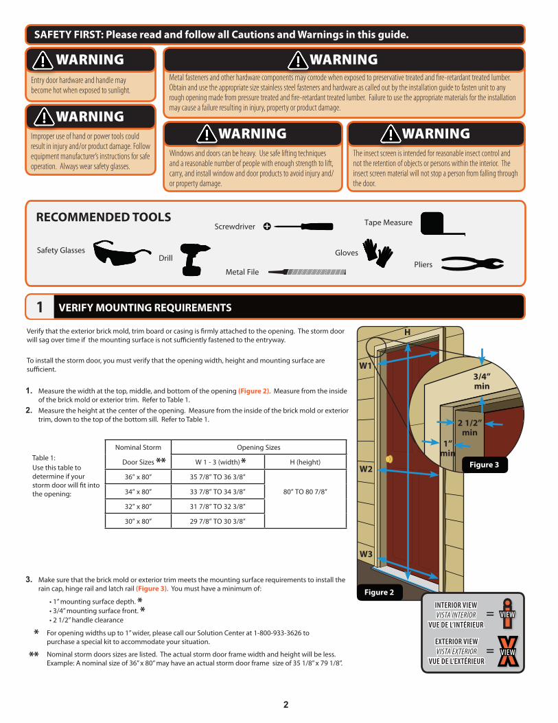
Verify that the exterior brick mold, trim board or casing is firmly attached to the opening. The storm door will sag over time if the mounting surface is not sufficiently fastened to the entryway.
To install the storm door, you must verify that the opening width, height and mounting surface are sufficient.
1. Measure the width at the top, middle, and bottom of the opening (Figure 2). Measure from the inside of the brick mold or exterior trim. Refer to Table 1.
2. Measure the height at the center of the opening. Measure from the inside of the brick mold or exterior trim, down to the top of the bottom sill. Refer to Table 1.
3. Make sure that the brick mold or exterior trim meets the mounting surface requirements to install the rain cap, hinge rail and latch rail (Figure 3). You must have a minimum of:
• 1” mounting surface depth.• 3/4” mounting surface front.• 2 1/2” handle clearance
**
* For opening widths up to 1” wider, please call our Solution Center at 1-800-933-3626 to purchase a special kit to accommodate your situation.
SAFETY FIRST: Please read and follow all Cautions and Warnings in this guide.
VERIFY MOUNTING REQUIREMENTS1
RECOMMENDED TOOLS
DrillSafety Glasses
Tape Measure
3/4”min
2 1/2”min
1”min
H
W1
W2
W3
Figure 3
Figure 2
Gloves
!!
1/2”
1/2”
1/2”
1”
1 1/2”
2”1 1/2”
5/8”
5/8”
Table 1:Use this table to determine if your storm door will fit into the opening:
Nominal Storm Opening Sizes
Door Sizes W 1 - 3 (width) H (height)
36” x 80” 35 7/8” TO 36 3/8”
34” x 80” 33 7/8” TO 34 3/8” 80” TO 80 7/8”
32” x 80” 31 7/8” TO 32 3/8”
30” x 80” 29 7/8” TO 30 3/8”
***
** Nominal storm doors sizes are listed. The actual storm door frame width and height will be less. Example: A nominal size of 36” x 80” may have an actual storm door frame size of 35 1/8” x 79 1/8”.
Entry door hardware and handle may become hot when exposed to sunlight.
WARNING
Improper use of hand or power tools could result in injury and/or product damage. Follow equipment manufacturer’s instructions for safe operation. Always wear safety glasses.
WARNING
Windows and doors can be heavy. Use safe lifting techniques and a reasonable number of people with enough strength to lift, carry, and install window and door products to avoid injury and/or property damage.
WARNINGThe insect screen is intended for reasonable insect control and not the retention of objects or persons within the interior. The insect screen material will not stop a person from falling through the door.
WARNING
Metal fasteners and other hardware components may corrode when exposed to preservative treated and fire-retardant treated lumber. Obtain and use the appropriate size stainless steel fasteners and hardware as called out by the installation guide to fasten unit to any rough opening made from pressure treated and fire-retardant treated lumber. Failure to use the appropriate materials for the installation may cause a failure resulting in injury, property or product damage.
WARNING
Screwdriver
!!
1/2”
1/2”
1/2”
1”
1 1/2”
2”1 1/2”
5/8”
5/8”
=
= XVIEW
iVIEW
EXTERIOR VIEWVISTA EXTERIOR
VUE DE L’EXTÉRIEUR
INTERIOR VIEWVISTA INTERIOR
VUE DE L’INTÉRIEUR
!!
1/2”
1/2”
1/2”
1”
1 1/2”
2”1 1/2”
5/8”
5/8”
PliersMetal File
3
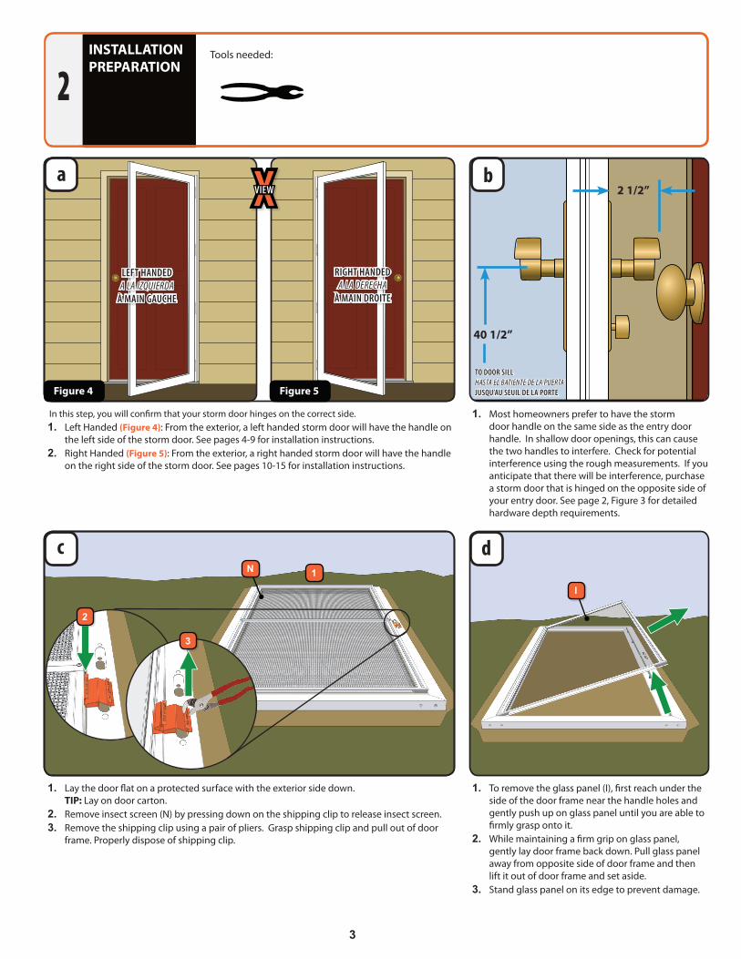
INSTALLATION PREPARATION
2
a b
1. Most homeowners prefer to have the storm door handle on the same side as the entry door handle. In shallow door openings, this can cause the two handles to interfere. Check for potential interference using the rough measurements. If you anticipate that there will be interference, purchase a storm door that is hinged on the opposite side of your entry door. See page 2, Figure 3 for detailed hardware depth requirements.
1. To remove the glass panel (I), first reach under the side of the door frame near the handle holes and gently push up on glass panel until you are able to firmly grasp onto it.
2. While maintaining a firm grip on glass panel, gently lay door frame back down. Pull glass panel away from opposite side of door frame and then lift it out of door frame and set aside.
3. Stand glass panel on its edge to prevent damage.
1. Lay the door flat on a protected surface with the exterior side down. TIP: Lay on door carton.
2. Remove insect screen (N) by pressing down on the shipping clip to release insect screen.3. Remove the shipping clip using a pair of pliers. Grasp shipping clip and pull out of door
frame. Properly dispose of shipping clip.
In this step, you will confirm that your storm door hinges on the correct side.1. Left Handed (Figure 4): From the exterior, a left handed storm door will have the handle on
the left side of the storm door. See pages 4-9 for installation instructions.2. Right Handed (Figure 5): From the exterior, a right handed storm door will have the handle
on the right side of the storm door. See pages 10-15 for installation instructions.
Figure 4 Figure 5
2 1/2”
40 1/2”
c d
Tools needed:
LEFT HANDEDA LA IZQUIERDA
À MAIN GAUCHE
RIGHT HANDEDA LA DERECHA
À MAIN DROITE
XVIEW
TO DOOR SILLHASTA EL BATIENTE DE LA PUERTAJUSQU’AU SEUIL DE LA PORTE
!!
1/2”
1/2”
1/2”
1”
1 1/2”
2”1 1/2”
5/8”
5/8”
2
1
3
N
I
4
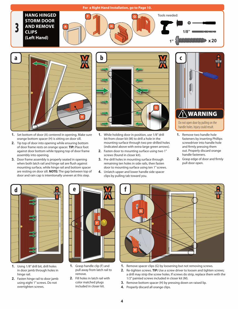
1. While holding door in position, use 1/8” drill bit from closer kit (M) to drill a hole in the mounting surface through two pre-drilled holes (indicated above with extra-large green arrows).
2. Fasten door to mounting surface using two 1” screws (found in closer kit).
3. Pre-drill holes in mounting surface through remaining ten holes in side rails, then fasten door to mounting surface using ten 1” screws.
4. Unlatch upper and lower handle side spacer clips by pulling tab toward you.
1. Remove two handle hole fasteners by inserting Phillips screwdriver into handle hole and firmly pressing them out. Properly discard orange handle fasteners.
2. Grasp edge of door and firmly pull door open.
1. Using 1/8” drill bit, drill holes in door jamb through holes in hinge rail.
2. Fasten hinge rail to door jamb using eight 1” screws. Do not overtighten screws.
1. Grasp handle clip (F) and pull away from latch rail to remove.
2. Fill holes in latch rail with color matched plugs included in closer kit.
1. Remove spacer clips (G) by loosening but not removing screws.2. Re-tighten screws. TIP: Use a screw driver to loosen and tighten screws;
a drill may strip the screw holes. If screws do strip, replace them with the 1/2” painted screws included in closer kit (M).
3. Remove bottom spacer (H) by pressing down on raised lip.4. Properly discard all orange clips.
1. Set bottom of door (A) centered in opening. Make sure orange bottom spacer (H) is sitting on door sill.
2. Tip top of door into opening while ensuring bottom of door frame rests on orange spacer. TIP: Place foot against door bottom while tipping top of door frame assembly into opening.
3. Door frame assembly is properly seated in opening when both latch rail and hinge rail are flush against mounting surface, while hinge rail and bottom spacer are resting on door sill. NOTE: The gap between top of door and rain cap is intentionally uneven at this step.
Tools needed:HANG HINGED STORM DOOR AND REMOVE CLIPS(Left Hand)
3
e
b
f
c
d
a
For a Right Hand Installation, go to Page 10.
!!
1/2”
1/2”
1/2”
1”
1 1/2”
2”1 1/2”
5/8”
5/8”
Do not open door by pulling on the handle holes. Injury could result.
WARNING
A
F
H
G
1” x 20
1/8”
!!
1/2”
1/2”
1/2”
1”
1 1/2”
2”1 1/2”
5/8”
5/8”
#8
#10
#12
#63/4” Machine Pan Painted
1/2” SMS Pan
1/2” SMS Pan Painted
1/2” SMS Flathead
1/2” Self-Drill Pan
1/2” Self-Drill Pan Painted
3/4” Machine Flathead
7/8” Machine Pan Painted
1” SMS Pan
1” SMS Pan Painted
1” Machine Pan Painted
1-1/2” Machine Flathead
1-1/2” Machine Flathead
2” SMS Pan Painted
5/8” SMS Pan Painted
1-1/4” SMS Pan
iVIEW iVIEW
iVIEWXVIEW XVIEW
XVIEW
F
G
G
H
H
5
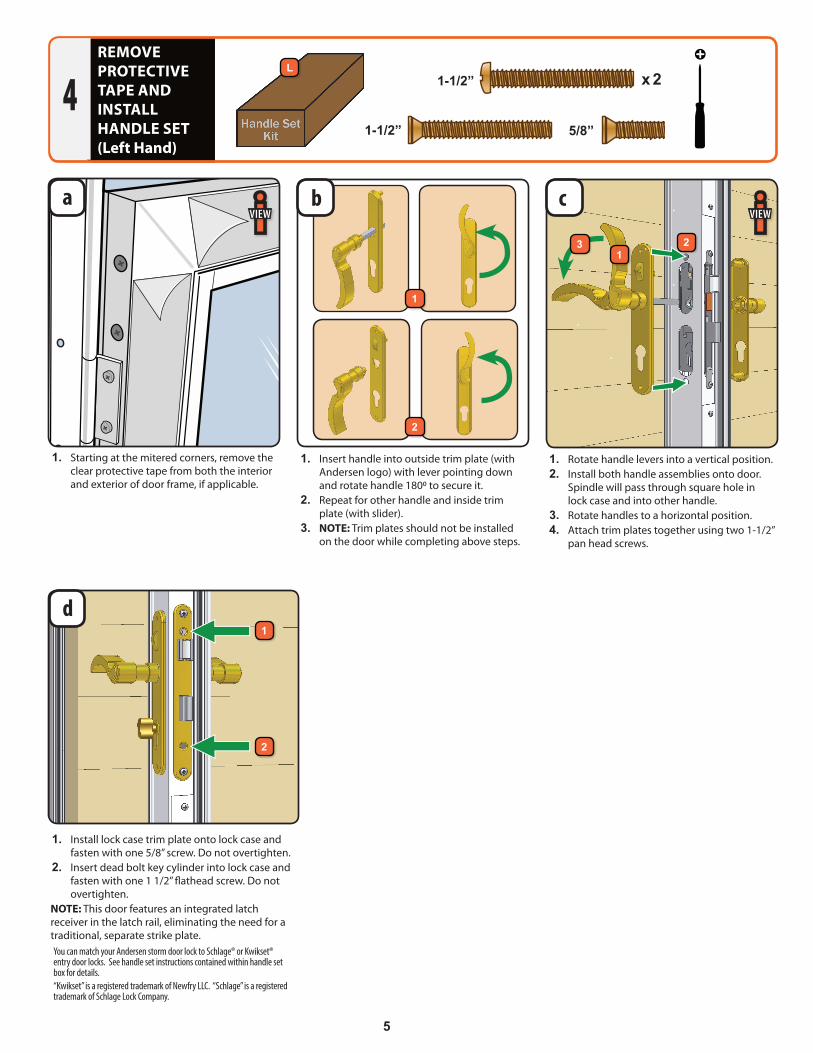
You can match your Andersen storm door lock to Schlage® or Kwikset® entry door locks. See handle set instructions contained within handle set box for details. “Kwikset” is a registered trademark of Newfry LLC. “Schlage” is a registered trademark of Schlage Lock Company.
1. Starting at the mitered corners, remove the clear protective tape from both the interior and exterior of door frame, if applicable.
1. Install lock case trim plate onto lock case and fasten with one 5/8” screw. Do not overtighten.
2. Insert dead bolt key cylinder into lock case and fasten with one 1 1/2” flathead screw. Do not overtighten.
NOTE: This door features an integrated latch receiver in the latch rail, eliminating the need for a traditional, separate strike plate.
1. Insert handle into outside trim plate (with Andersen logo) with lever pointing down and rotate handle 1800 to secure it.
2. Repeat for other handle and inside trim plate (with slider).
3. NOTE: Trim plates should not be installed on the door while completing above steps.
1. Rotate handle levers into a vertical position.2. Install both handle assemblies onto door.
Spindle will pass through square hole in lock case and into other handle.
3. Rotate handles to a horizontal position.4. Attach trim plates together using two 1-1/2”
pan head screws.
REMOVE PROTECTIVE TAPE AND INSTALL HANDLE SET(Left Hand)
4
d
a c
L
5/8”
1-1/2” x 2
1-1/2” !!
1/2”
1/2”
1/2”
1”
1 1/2”
2”1 1/2”
5/8”
5/8”
b
1
2
1
12
2
#8
#10
#12
#63/4” Machine Pan Painted
1/2” SMS Pan
1/2” SMS Pan Painted
1/2” SMS Flathead
1/2” Self-Drill Pan
1/2” Self-Drill Pan Painted
3/4” Machine Flathead
7/8” Machine Pan Painted
1” SMS Pan
1” SMS Pan Painted
1” Machine Pan Painted
1-1/2” Machine Flathead
1-1/2” Machine Flathead
2” SMS Pan Painted
5/8” SMS Pan Painted
1-1/4” SMS Pan
#8
#10
#12
#63/4” Machine Pan Painted
1/2” SMS Pan
1/2” SMS Pan Painted
1/2” SMS Flathead
1/2” Self-Drill Pan
1/2” Self-Drill Pan Painted
3/4” Machine Flathead
7/8” Machine Pan Painted
1” SMS Pan
1” SMS Pan Painted
1” Machine Pan Painted
1-1/2” Machine Flathead
1-1/2” Machine Flathead
2” SMS Pan Painted
5/8” SMS Pan Painted
1-1/4” SMS Pan#8
#10
#12
#63/4” Machine Pan Painted
1/2” SMS Pan
1/2” SMS Pan Painted
1/2” SMS Flathead
1/2” Self-Drill Pan
1/2” Self-Drill Pan Painted
3/4” Machine Flathead
7/8” Machine Pan Painted
1” SMS Pan
1” SMS Pan Painted
1” Machine Pan Painted
1-1/2” Machine Flathead
1-1/2” Machine Flathead
2” SMS Pan Painted
5/8” SMS Pan Painted
1-1/4” SMS Pan
iVIEW iVIEW
3
6
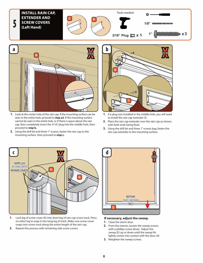
If necessary, adjust the sweep.1. Close the storm door.2. From the interior, loosen the sweep screws
with a phillips screw driver. Adjust the sweep (E) up or down until the sweep fin lightly comes into contact with the door sill.
3. Retighten the sweep screws.
d
INSTALL RAIN CAP, EXTENDER AND SCREW COVERS(Left Hand)5
BOTTOMPARTE INFERIOR
BAS
iVIEW
E
1. Lock leg of screw cover (K) into short leg of rain cap screw track. Press on other leg to snap it into long leg of track. Make sure screw cover snaps into screw track along the entire length of the rain cap.
2. Repeat this process with remaining side screw covers.
SHORT LEGPESTAÑA CORTA
RAINURE COURTE
K
K
XVIEWc
Tools needed:
1/8”
!!
1/2”
1/2”
1/2”
1”
1 1/2”
2”1 1/2”
5/8”
5/8”
1” x 3
#8
#10
#12
#63/4” Machine Pan Painted
1/2” SMS Pan
1/2” SMS Pan Painted
1/2” SMS Flathead
1/2” Self-Drill Pan
1/2” Self-Drill Pan Painted
3/4” Machine Flathead
7/8” Machine Pan Painted
1” SMS Pan
1” SMS Pan Painted
1” Machine Pan Painted
1-1/2” Machine Flathead
1-1/2” Machine Flathead
2” SMS Pan Painted
5/8” SMS Pan Painted
1-1/4” SMS Pan
!!
1/2”
1/2”
1/2”
1”
1 1/2”
2”1 1/2”
5/8”
5/8”
a XVIEWb XVIEW
B
B
J
J K
1. Look at the center hole of the rain cap. If the mounting surface can be seen in the entire hole, proceed to step a2. If the mounting surface cannot be seen in the entire hole, or if there is space above the rain cap, then completely insert the 3/16” plug into the middle hole, then proceed to step b.
2. Using the drill bit and three 1” screws, fasten the rain cap to the mounting surface, then proceed to step c.
1. If a plug was installed in the middle hole, you will need to install the rain cap extender (I).
2. Place the rain cap extender over the rain cap as shown, with both ends being flush.
3. Using the drill bit and three 1” screws bag, fasten the rain cap extender to the mounting surface.
3/16” Plug x 1
1
2
3
12
9
4
13
14
5
6
7
8
NO 1
7
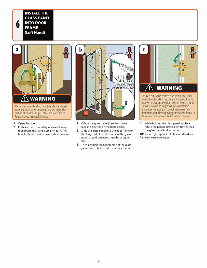
1. Open the door.2. Push and hold the safety release slide up,
then rotate the handle up a 1/4 turn. The handle should now be in a vertical position.
1. Orient the glass panel (I) so the notches face the exterior, on the handle side.
2. Slide the glass panel into the door frame on the hinge side first. The frame of the glass panel should be seated into the snugger bar.
3. Then position the handle side of the glass panel until it is flush with the door frame.
1. While holding the glass panel in place, rotate the handle down a 1/4 turn to lock the glass panel in door frame.
TIP: Ensure glass panel is fully seated in door frame for easy operation.
INSTALL THE GLASS PANEL INTO DOOR FRAME(Left Hand)
6
iVIEW iVIEWiVIEWa b c
The notches located on backside of handle side of glass panel and insect screen may contain sharp edges. Use caution when handling glass panel and insect screen. Failure to do so may result in injury.
WARNINGThe glass panel/insect screen is secured in door frame by door handle locking mechanism. Once door handle has been rotated up to vertical position, the glass panel /insect screen are no longer secured in door frame. Immediately remove glass panel/insect screen from door frame after releasing locking mechanism. Failure to do so could result in injury and/or product damage.
WARNINGSNUGGER BAR
BARRA DE SOPORTEBARRE DE CALAGE
I
8
INSTALL CLOSERS(Left Hand)7
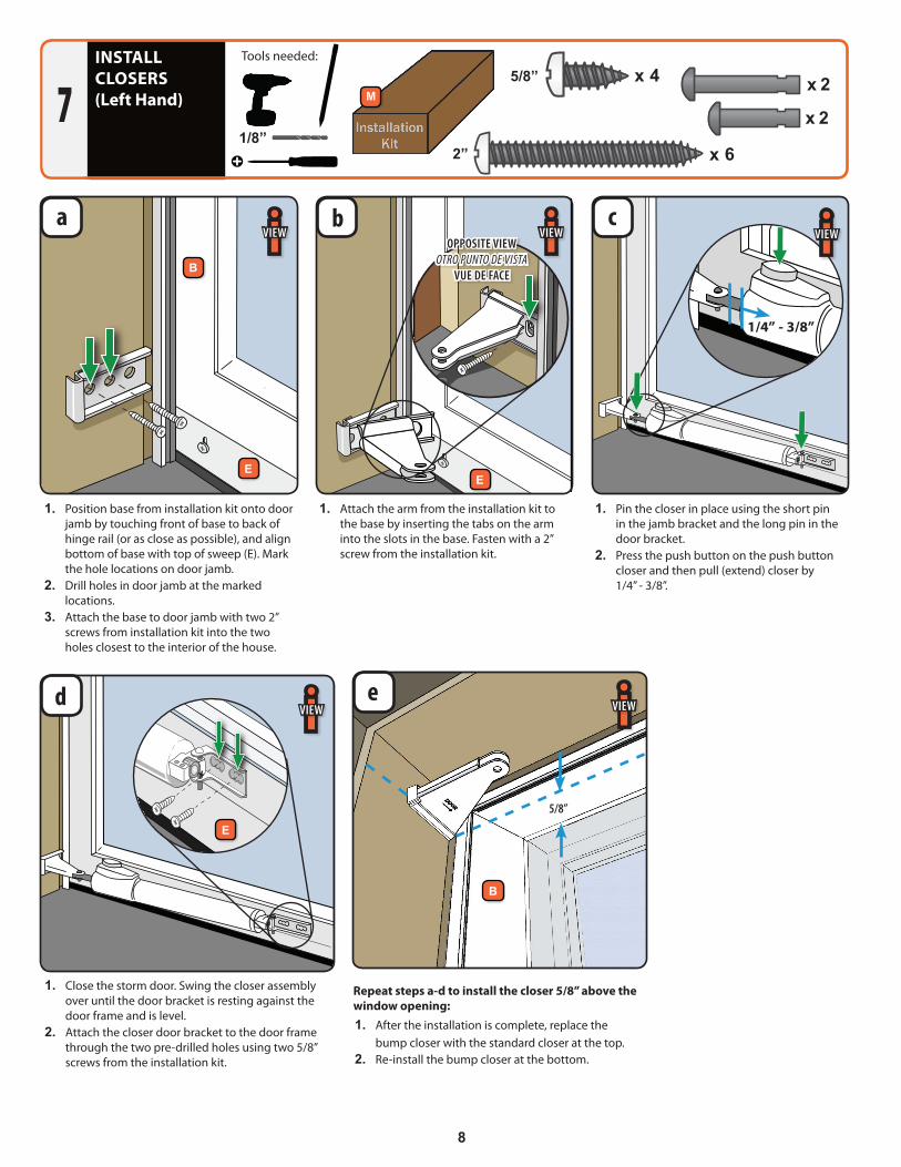
1. Pin the closer in place using the short pin in the jamb bracket and the long pin in the door bracket.
2. Press the push button on the push button closer and then pull (extend) closer by 1/4” - 3/8”.
1. Attach the arm from the installation kit to the base by inserting the tabs on the arm into the slots in the base. Fasten with a 2” screw from the installation kit.
a b cOPPOSITE VIEW
OTRO PUNTO DE VISTAVUE DE FACE
EE
iVIEW iVIEW
1. Close the storm door. Swing the closer assembly over until the door bracket is resting against the door frame and is level.
2. Attach the closer door bracket to the door frame through the two pre-drilled holes using two 5/8” screws from the installation kit.
d
E
iVIEW
1. Position base from installation kit onto door jamb by touching front of base to back of hinge rail (or as close as possible), and align bottom of base with top of sweep (E). Mark the hole locations on door jamb.
2. Drill holes in door jamb at the marked locations.
3. Attach the base to door jamb with two 2” screws from installation kit into the two holes closest to the interior of the house.
Repeat steps a-d to install the closer 5/8” above the window opening:1. After the installation is complete, replace the
bump closer with the standard closer at the top.2. Re-install the bump closer at the bottom.
1/4” - 3/8”
iVIEW
5/8”
e
1/8”
!!
1/2”
1/2”
1/2”
1”
1 1/2”
2”1 1/2”
5/8”
5/8”
Tools needed:
!!
1/2”
1/2”
1/2”
1”
1 1/2”
2”1 1/2”
5/8”
5/8”
x 45/8”
#8
#10
#12
#63/4” Machine Pan Painted
1/2” SMS Pan
1/2” SMS Pan Painted
1/2” SMS Flathead
1/2” Self-Drill Pan
1/2” Self-Drill Pan Painted
3/4” Machine Flathead
7/8” Machine Pan Painted
1” SMS Pan
1” SMS Pan Painted
1” Machine Pan Painted
1-1/2” Machine Flathead
1-1/2” Machine Flathead
2” SMS Pan Painted
5/8” SMS Pan Painted
1-1/4” SMS Pan
x 2
#8
#10
#12
#63/4” Machine Pan Painted
1/2” SMS Pan
1/2” SMS Pan Painted
1/2” SMS Flathead
1/2” Self-Drill Pan
1/2” Self-Drill Pan Painted
3/4” Machine Flathead
7/8” Machine Pan Painted
1” SMS Pan
1” SMS Pan Painted
1” Machine Pan Painted
1-1/2” Machine Flathead
1-1/2” Machine Flathead
2” SMS Pan Painted
5/8” SMS Pan Painted
1-1/4” SMS Pan
M
x 62”
#8
#10
#12
#63/4” Machine Pan Painted
1/2” SMS Pan
1/2” SMS Pan Painted
1/2” SMS Flathead
1/2” Self-Drill Pan
1/2” Self-Drill Pan Painted
3/4” Machine Flathead
7/8” Machine Pan Painted
1” SMS Pan
1” SMS Pan Painted
1” Machine Pan Painted
1-1/2” Machine Flathead
1-1/2” Machine Flathead
2” SMS Pan Painted
5/8” SMS Pan Painted
1-1/4” SMS Pan
iVIEW
B
B
9
TROUBLESHOOTING(Left Hand)For additional help with these, or any other installation steps, please call our Solution Center at 1-800-933-3626.
10
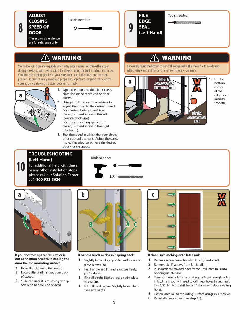
If your bottom spacer falls off or is out of position prior to fastening the door the the mounting surface:1. Hook the clip on to the sweep.2. Rotate clip until it snaps over back
of sweep.3. Slide clip until it is touching sweep
screw on handle side of door.
If handle binds or doesn’t spring back:1. Slightly loosen key cylinder and lockcase
plate screws (A).2. Test handle set. If handle moves freely,
you’re done.3. If it still binds: Slightly loosen trim plate
screws (B).4. If it still binds again: Slightly loosen lock
case screws (C).
If door isn’t latching onto latch rail:1. Remove screw cover from latch rail (if installed).2. Remove six 1” screws from latch rail.3. Push latch rail toward door frame until latch falls into
opening in latch rail.4. If you can see holes in mounting surface through holes
in latch rail, you will need to drill new holes in latch rail. Use 1/8” drill bit to drill holes 1” above or below existing holes.
5. Fasten latch rail to mounting surface using six 1” screws.6. Reinstall screw cover (see step 5c).
b ca
!!
1/2”
1/2”
1/2”
1”
1 1/2”
2”1 1/2”
5/8”
5/8”
1/8”
!!
1/2”
1/2”
1/2”
1”
1 1/2”
2”1 1/2”
5/8”
5/8”
Tools needed:
XVIEW
B A CH
Tools needed:FILE EDGE SEAL(Left Hand)9
Generously round the bottom corner of the edge seal with a metal file to avoid sharp edges. Failure to round the bottom corners may cause an injury.
WARNING
1. File the bottom corner of the edge seal until it’s smooth.
a EDGE SEALJOINT DE REBORD
SELLO DEL BORDE
BOTTOMPARTE INFERIOR
BAS
XVIEW
Ea
1. Open the door and then let it close. Note the speed at which the door closes.
2. Using a Phillips head screwdriver to adjust the closer to the desired speed: For a faster closing speed, turn the adjustment screw to the left (counterclockwise). For a slower closing speed, turn the adjustment screw to the right (clockwise).
3. Test the speed at which the door closes after each adjustment. Adjust the screw more, if needed, to achieve the desired door closing speed.
ADJUST CLOSING SPEED OF DOORCloser and door shown are for reference only.
8Tools needed:
Storm door will close more quickly when entry door is open. To achieve the proper closing speed, you will need to adjust the closer(s) using the built-in adjustment screw. Check for safe closing speed with your entry door in both the closed and the open position. To prevent injury, make sure people and/or pets are completely through the opening before allowing the storm door to shut freely.
WARNING
!!
1/2”
1/2”
1/2”
1”
1 1/2”
2”1 1/2”
5/8”
5/8”
iVIEW
10
HANG HINGED STORM DOOR AND REMOVE CLIPS(Right Hand)
11
For a Left Hand Installation, go to Page 4.
Tools needed:
!!
1/2”
1/2”
1/2”
1”
1 1/2”
2”1 1/2”
5/8”
5/8”
F
H
G
1” x 20
1/8”
!!
1/2”
1/2”
1/2”
1”
1 1/2”
2”1 1/2”
5/8”
5/8”
#8
#10
#12
#63/4” Machine Pan Painted
1/2” SMS Pan
1/2” SMS Pan Painted
1/2” SMS Flathead
1/2” Self-Drill Pan
1/2” Self-Drill Pan Painted
3/4” Machine Flathead
7/8” Machine Pan Painted
1” SMS Pan
1” SMS Pan Painted
1” Machine Pan Painted
1-1/2” Machine Flathead
1-1/2” Machine Flathead
2” SMS Pan Painted
5/8” SMS Pan Painted
1-1/4” SMS Pan
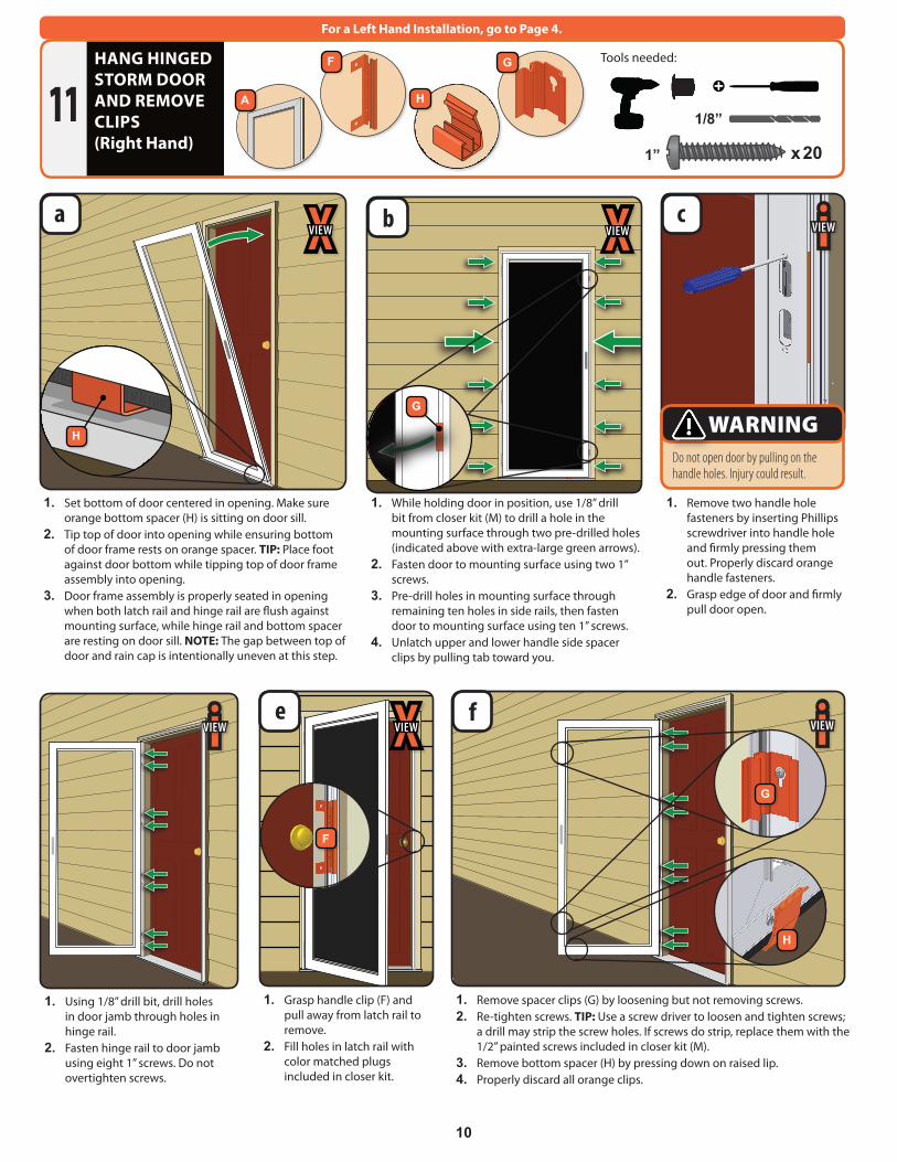
1. While holding door in position, use 1/8” drill bit from closer kit (M) to drill a hole in the mounting surface through two pre-drilled holes (indicated above with extra-large green arrows).
2. Fasten door to mounting surface using two 1” screws.
3. Pre-drill holes in mounting surface through remaining ten holes in side rails, then fasten door to mounting surface using ten 1” screws.
4. Unlatch upper and lower handle side spacer clips by pulling tab toward you.
1. Remove two handle hole fasteners by inserting Phillips screwdriver into handle hole and firmly pressing them out. Properly discard orange handle fasteners.
2. Grasp edge of door and firmly pull door open.
1. Using 1/8” drill bit, drill holes in door jamb through holes in hinge rail.
2. Fasten hinge rail to door jamb using eight 1” screws. Do not overtighten screws.
1. Grasp handle clip (F) and pull away from latch rail to remove.
2. Fill holes in latch rail with color matched plugs included in closer kit.
1. Remove spacer clips (G) by loosening but not removing screws.2. Re-tighten screws. TIP: Use a screw driver to loosen and tighten screws;
a drill may strip the screw holes. If screws do strip, replace them with the 1/2” painted screws included in closer kit (M).
3. Remove bottom spacer (H) by pressing down on raised lip.4. Properly discard all orange clips.
1. Set bottom of door centered in opening. Make sure orange bottom spacer (H) is sitting on door sill.
2. Tip top of door into opening while ensuring bottom of door frame rests on orange spacer. TIP: Place foot against door bottom while tipping top of door frame assembly into opening.
3. Door frame assembly is properly seated in opening when both latch rail and hinge rail are flush against mounting surface, while hinge rail and bottom spacer are resting on door sill. NOTE: The gap between top of door and rain cap is intentionally uneven at this step.
e f
ca
Do not open door by pulling on the handle holes. Injury could result.
WARNING
iVIEW iVIEW
iVIEWXVIEW
XVIEW
F
G
H
H
A
b XVIEW
G
11
REMOVE PROTECTIVE TAPE AND INSTALL HANDLE SET(Right Hand)
12L
5/8”
1-1/2” x 2
1-1/2” !!
1/2”
1/2”
1/2”
1”
1 1/2”
2”1 1/2”
5/8”
5/8”
#8
#10
#12
#63/4” Machine Pan Painted
1/2” SMS Pan
1/2” SMS Pan Painted
1/2” SMS Flathead
1/2” Self-Drill Pan
1/2” Self-Drill Pan Painted
3/4” Machine Flathead
7/8” Machine Pan Painted
1” SMS Pan
1” SMS Pan Painted
1” Machine Pan Painted
1-1/2” Machine Flathead
1-1/2” Machine Flathead
2” SMS Pan Painted
5/8” SMS Pan Painted
1-1/4” SMS Pan
#8
#10
#12
#63/4” Machine Pan Painted
1/2” SMS Pan
1/2” SMS Pan Painted
1/2” SMS Flathead
1/2” Self-Drill Pan
1/2” Self-Drill Pan Painted
3/4” Machine Flathead
7/8” Machine Pan Painted
1” SMS Pan
1” SMS Pan Painted
1” Machine Pan Painted
1-1/2” Machine Flathead
1-1/2” Machine Flathead
2” SMS Pan Painted
5/8” SMS Pan Painted
1-1/4” SMS Pan#8
#10
#12
#63/4” Machine Pan Painted
1/2” SMS Pan
1/2” SMS Pan Painted
1/2” SMS Flathead
1/2” Self-Drill Pan
1/2” Self-Drill Pan Painted
3/4” Machine Flathead
7/8” Machine Pan Painted
1” SMS Pan
1” SMS Pan Painted
1” Machine Pan Painted
1-1/2” Machine Flathead
1-1/2” Machine Flathead
2” SMS Pan Painted
5/8” SMS Pan Painted
1-1/4” SMS Pan
You can match your Andersen storm door lock to Schlage® or Kwikset® entry door locks. See handle set instructions contained within handle set box for details. “Kwikset” is a registered trademark of Newfry LLC. “Schlage” is a registered trademark of Schlage Lock Company.
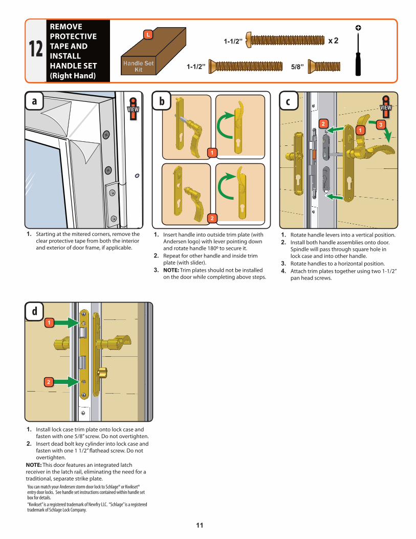
1. Starting at the mitered corners, remove the clear protective tape from both the interior and exterior of door frame, if applicable.
1. Install lock case trim plate onto lock case and fasten with one 5/8” screw. Do not overtighten.
2. Insert dead bolt key cylinder into lock case and fasten with one 1 1/2” flathead screw. Do not overtighten.
NOTE: This door features an integrated latch receiver in the latch rail, eliminating the need for a traditional, separate strike plate.
1. Insert handle into outside trim plate (with Andersen logo) with lever pointing down and rotate handle 1800 to secure it.
2. Repeat for other handle and inside trim plate (with slider).
3. NOTE: Trim plates should not be installed on the door while completing above steps.
1. Rotate handle levers into a vertical position.2. Install both handle assemblies onto door.
Spindle will pass through square hole in lock case and into other handle.
3. Rotate handles to a horizontal position.4. Attach trim plates together using two 1-1/2”
pan head screws.
d
a cb
1
2
1
12
2
iVIEW iVIEW
3
12
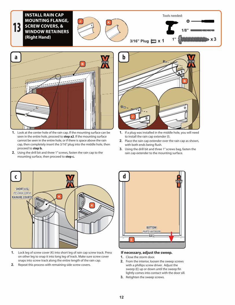
If necessary, adjust the sweep.1. Close the storm door.2. From the interior, loosen the sweep screws
with a phillips screw driver. Adjust the sweep (E) up or down until the sweep fin lightly comes into contact with the door sill.
3. Retighten the sweep screws.
d
INSTALL RAIN CAP MOUNTING FLANGE, SCREW COVERS, & WINDOW RETAINERS(Right Hand)
13
BOTTOMPARTE INFERIOR
BAS
iVIEW
E
1. Lock leg of screw cover (K) into short leg of rain cap screw track. Press on other leg to snap it into long leg of track. Make sure screw cover snaps into screw track along the entire length of the rain cap.
2. Repeat this process with remaining side screw covers.
K
K
XVIEWc
Tools needed:
1/8”
!!
1/2”
1/2”
1/2”
1”
1 1/2”
2”1 1/2”
5/8”
5/8”
1” x 3
#8
#10
#12
#63/4” Machine Pan Painted
1/2” SMS Pan
1/2” SMS Pan Painted
1/2” SMS Flathead
1/2” Self-Drill Pan
1/2” Self-Drill Pan Painted
3/4” Machine Flathead
7/8” Machine Pan Painted
1” SMS Pan
1” SMS Pan Painted
1” Machine Pan Painted
1-1/2” Machine Flathead
1-1/2” Machine Flathead
2” SMS Pan Painted
5/8” SMS Pan Painted
1-1/4” SMS Pan
!!
1/2”
1/2”
1/2”
1”
1 1/2”
2”1 1/2”
5/8”
5/8”
SHORT LEGPESTAÑA CORTA
RAINURE COURTE
a XVIEWb XVIEW
B
B
J
J K
1. Look at the center hole of the rain cap. If the mounting surface can be seen in the entire hole, proceed to step a2. If the mounting surface cannot be seen in the entire hole, or if there is space above the rain cap, then completely insert the 3/16” plug into the middle hole, then proceed to step b.
2. Using the drill bit and three 1” screws, fasten the rain cap to the mounting surface, then proceed to step c.
1. If a plug was installed in the middle hole, you will need to install the rain cap extender (I).
2. Place the rain cap extender over the rain cap as shown, with both ends being flush.
3. Using the drill bit and three 1” screws bag, fasten the rain cap extender to the mounting surface.
3/16” Plug x 1
1
2
3
12
9
4
13
14
5
6
7
8
NO 1
13
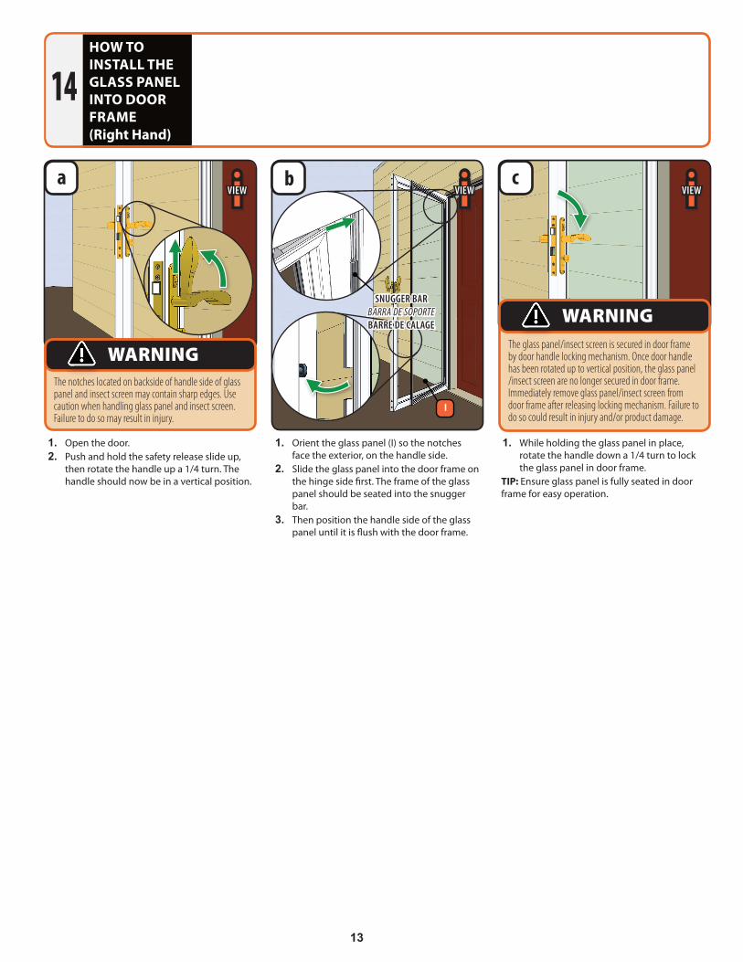
1. Open the door.2. Push and hold the safety release slide up,
then rotate the handle up a 1/4 turn. The handle should now be in a vertical position.
1. Orient the glass panel (I) so the notches face the exterior, on the handle side.
2. Slide the glass panel into the door frame on the hinge side first. The frame of the glass panel should be seated into the snugger bar.
3. Then position the handle side of the glass panel until it is flush with the door frame.
1. While holding the glass panel in place, rotate the handle down a 1/4 turn to lock the glass panel in door frame.
TIP: Ensure glass panel is fully seated in door frame for easy operation.
HOW TO INSTALL THE GLASS PANEL INTO DOOR FRAME(Right Hand)
14
iVIEW iVIEWiVIEWa b c
The notches located on backside of handle side of glass panel and insect screen may contain sharp edges. Use caution when handling glass panel and insect screen. Failure to do so may result in injury.
WARNINGThe glass panel/insect screen is secured in door frame by door handle locking mechanism. Once door handle has been rotated up to vertical position, the glass panel /insect screen are no longer secured in door frame. Immediately remove glass panel/insect screen from door frame after releasing locking mechanism. Failure to do so could result in injury and/or product damage.
WARNINGSNUGGER BAR
BARRA DE SOPORTEBARRE DE CALAGE
I
14
INSTALL CLOSERS(Right Hand)15
1/8”
!!
1/2”
1/2”
1/2”
1”
1 1/2”
2”1 1/2”
5/8”
5/8”
Tools needed:
!!
1/2”
1/2”
1/2”
1”
1 1/2”
2”1 1/2”
5/8”
5/8”
x 45/8”
#8
#10
#12
#63/4” Machine Pan Painted
1/2” SMS Pan
1/2” SMS Pan Painted
1/2” SMS Flathead
1/2” Self-Drill Pan
1/2” Self-Drill Pan Painted
3/4” Machine Flathead
7/8” Machine Pan Painted
1” SMS Pan
1” SMS Pan Painted
1” Machine Pan Painted
1-1/2” Machine Flathead
1-1/2” Machine Flathead
2” SMS Pan Painted
5/8” SMS Pan Painted
1-1/4” SMS Pan
x 2
#8
#10
#12
#63/4” Machine Pan Painted
1/2” SMS Pan
1/2” SMS Pan Painted
1/2” SMS Flathead
1/2” Self-Drill Pan
1/2” Self-Drill Pan Painted
3/4” Machine Flathead
7/8” Machine Pan Painted
1” SMS Pan
1” SMS Pan Painted
1” Machine Pan Painted
1-1/2” Machine Flathead
1-1/2” Machine Flathead
2” SMS Pan Painted
5/8” SMS Pan Painted
1-1/4” SMS Pan
x 2
#8
#10
#12
#63/4” Machine Pan Painted
1/2” SMS Pan
1/2” SMS Pan Painted
1/2” SMS Flathead
1/2” Self-Drill Pan
1/2” Self-Drill Pan Painted
3/4” Machine Flathead
7/8” Machine Pan Painted
1” SMS Pan
1” SMS Pan Painted
1” Machine Pan Painted
1-1/2” Machine Flathead
1-1/2” Machine Flathead
2” SMS Pan Painted
5/8” SMS Pan Painted
1-1/4” SMS Pan
M
x 62”
#8
#10
#12
#63/4” Machine Pan Painted
1/2” SMS Pan
1/2” SMS Pan Painted
1/2” SMS Flathead
1/2” Self-Drill Pan
1/2” Self-Drill Pan Painted
3/4” Machine Flathead
7/8” Machine Pan Painted
1” SMS Pan
1” SMS Pan Painted
1” Machine Pan Painted
1-1/2” Machine Flathead
1-1/2” Machine Flathead
2” SMS Pan Painted
5/8” SMS Pan Painted
1-1/4” SMS Pan
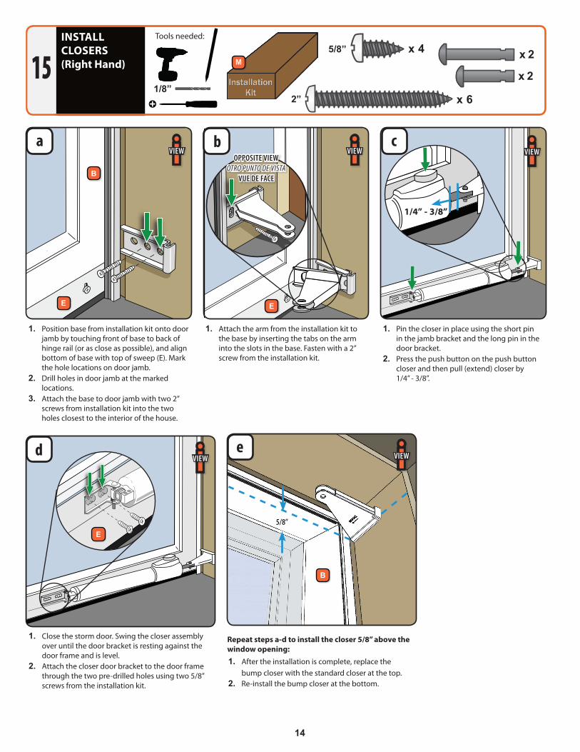
1. Pin the closer in place using the short pin in the jamb bracket and the long pin in the door bracket.
2. Press the push button on the push button closer and then pull (extend) closer by 1/4” - 3/8”.
1. Attach the arm from the installation kit to the base by inserting the tabs on the arm into the slots in the base. Fasten with a 2” screw from the installation kit.
a b cOPPOSITE VIEW
OTRO PUNTO DE VISTAVUE DE FACE
E E
iVIEW iVIEW
1. Close the storm door. Swing the closer assembly over until the door bracket is resting against the door frame and is level.
2. Attach the closer door bracket to the door frame through the two pre-drilled holes using two 5/8” screws from the installation kit.
d
E
iVIEW
1. Position base from installation kit onto door jamb by touching front of base to back of hinge rail (or as close as possible), and align bottom of base with top of sweep (E). Mark the hole locations on door jamb.
2. Drill holes in door jamb at the marked locations.
3. Attach the base to door jamb with two 2” screws from installation kit into the two holes closest to the interior of the house.
Repeat steps a-d to install the closer 5/8” above the window opening:1. After the installation is complete, replace the
bump closer with the standard closer at the top.2. Re-install the bump closer at the bottom.
1/4” - 3/8”
iVIEW
5/8”
e
iVIEW
B
B
15
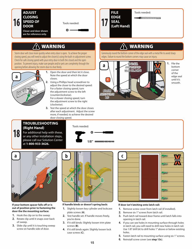
TROUBLESHOOTING(Right Hand)For additional help with these, or any other installation steps, please call our Solution Center at 1-800-933-3626.
18
If your bottom spacer falls off or is out of position prior to fastening the door the the mounting surface:1. Hook the clip on to the sweep2. Rotate clip until it snaps over back
of sweep.3. Slide clip until it is touching sweep
screw on handle side of door.
If door isn’t latching onto latch rail:1. Remove screw cover from latch rail (if installed).2. Remove six 1” screws from latch rail.3. Push latch rail toward door frame until latch falls into
opening in latch rail.4. If you can see holes in mounting surface through holes
in latch rail, you will need to drill new holes in latch rail. Use 1/8” drill bit to drill holes 1” above or below existing holes.
5. Fasten latch rail to mounting surface using six 1” screws.6. Reinstall screw cover (see step 13c).
ca
!!
1/2”
1/2”
1/2”
1”
1 1/2”
2”1 1/2”
5/8”
5/8”
1/8”
!!
1/2”
1/2”
1/2”
1”
1 1/2”
2”1 1/2”
5/8”
5/8”
Tools needed:
XVIEW
H
If handle binds or doesn’t spring back:1. Slightly loosen key cylinder and lockcase
plate screws (A).2. Test handle set. If handle moves freely,
you’re done.3. If it still binds: Slightly loosen trim plate
screws (B).4. If it still binds again: Slightly loosen lock
case screws (C).
b
BAC
Tools needed:FILE EDGE SEAL(Left Hand)17
Generously round the bottom corner of the edge seal with a metal file to avoid sharp edges. Failure to round the bottom corners may cause an injury.
WARNING
1. File the bottom corner of the edge seal until it’s smooth.
a EDGE SEALJOINT DE REBORD
SELLO DEL BORDE XVIEW
Ea
1. Open the door and then let it close. Note the speed at which the door closes.
2. Using a Phillips head screwdriver to adjust the closer to the desired speed: For a faster closing speed, turn the adjustment screw to the left (counterclockwise). For a slower closing speed, turn the adjustment screw to the right (clockwise).
3. Test the speed at which the door closes after each adjustment. Adjust the screw more, if needed, to achieve the desired door closing speed.
ADJUST CLOSING SPEED OF DOORCloser and door shown are for reference only.
16 Tools needed:
Storm door will close more quickly when entry door is open. To achieve the proper closing speed, you will need to adjust the closer(s) using the built-in adjustment screw. Check for safe closing speed with your entry door in both the closed and the open position. To prevent injury, make sure people and/or pets are completely through the opening before allowing the storm door to shut freely.
WARNING
!!
1/2”
1/2”
1/2”
1”
1 1/2”
2”1 1/2”
5/8”
5/8”
iVIEW
BOTTOMPARTE INFERIOR
BAS
16
CLEANING INSTRUCTIONS
LIMITED WARRANTIES
PRODUCT LIMITED WARRANTYDOOR FRAME: EMCO Enterprises, Inc. (EMCO) warrants the door frame, hinges, and painted finish on Andersen® aluminum storm door products to be free from defects in manufacturing, materials, paint adhesion, or workmanship, under normal use, for as long as the original consumer purchaser owns the home in which the door was initially installed.
COMPONENTS: EMCO warrants the non-glass and non-insect screen fabric components of Andersen® storm doors (including brass and nickel hardware finish and the mechanical functions of balancers, locksets, closers, windows and insect screens) to be free from defects in manufacturing, materials and workmanship for a period of five (5) years from the date of original retail purchase or for as long as the original consumer purchaser owns the home in which the door was initially installed, whichever is shorter. Insulated glass is also warranted for a period of five (5) years not to develop, under normal conditions, any material obstruction of vision resulting from manufacturing defects or as a result of premature failure of the glass or hermetic seal.
In the event a door frame, hinges, insulated glass or a component fails as a result of a defect in manufacturing, materials or workmanship within the limited warranty period specified above, and upon written proof of purchase, EMCO, at its option, will provide a replacement door frame, hinge, insulated glass unit and/or components without charge – installation is not included. Such replacement or repair is warranted for the remain-der of the original limited warranty period. Please locate the door serial number and written proof of purchase and contact EMCO Consumer Support at 1-800-933-3626. Warranty claims made one (1) year after purchase are subject to a flat processing fee.
“OOPS-PROOF” INSTALLATION LIMITED WARRANTYEMCO Enterprises, Inc. (EMCO) warrants that any part lost or mis-cut during the original installation of your Andersen storm door will be repaired or replaced at no additional charge within ninety (90) days of the date of original purchase. This limited warranty will not apply if the part has been misused, abused or altered. Cutting parts not specified by the installation guide or mis-drilled parts are not included in this warranty.
In the event a part is lost or mis-cut within the limited warranty period, EMCO, at its option, will provide the appropriate replacement part – installation is not included. Please locate the door serial number and written proof of purchase and contact EMCO Consumer Support at 1-800-933-3626.
GENERAL LIMITED WARRANTY INFORMATIONThe limited warranties set forth in this document are the only express warranties (whether written or oral) applicable to Andersen® storm doors, and no one is authorized to modify or expand these limited warranties. All warranty claims must be made during the applicable warranty periods.
ALL IMPLIED WARRANTIES INCLUDING MERCHANTABILITY AND FITNESS FOR A PARTICULAR PURPOSE ARE LIMITED TO THE APPLICABLE STATUTE OF LIMITATION, BUT IN NO CASE WILL EXTEND BEYOND THE TERM OF THE LIMITED WARRANTIES SET FORTH ABOVE. EMCO EXCLUDES AND WILL NOT PAY FOR INCIDENTAL OR CONSEQUENTIAL DAMAGES, WHETHER ARISING OUT OF CONTRACT, TORT OR OTHERWISE, AND ITS LIABILITY WILL IN ALL INSTANCES BE LIMITED TO THE REPAIR OR REPLACEMENT OF THE DEFECTIVE PRODUCT.
Some states do not allow the exclusion of incidental and consequential damages, or limitation of the duration of an implied warranty, so the above limitations or exclusions may not apply to you.
This limited warranty gives you specific legal rights, and you may also have other rights that may vary from state to state and in Canada.
What is NOT covered by this limited warranty: damage caused by 1) improper installation, maintenance, or use; 2) chemicals or airborne pollutants, such as salt or acid rain; 3) acts of God, including wind damage; 4) products not manufactured by EMCO
EMCO Enterprises, Inc. is a wholly owned subsidiary of Andersen Corporation. EMCO manufactures Andersen® and EMCO® storm doors. EMCO supports the limited warranties covering Andersen® Storm and Screen Doors. “Andersen”, “EMCO” and all other marks where denoted are trademarks of Andersen Corporation. ©2013 Andersen Corporation. All rights reserved.
Reprinted and effective as of May, 2011.
Online Parts and Knowledge Store
Andersen is committed to helping you find parts quickly and easily for your Andersen® or EMCO® storm door. Use the site below and your serial number to find many of the most-common replacement parts for your storm door.
This site also includes the Andersen Storm Door Learning Center. Whether you are trying to find other Andersen® or EMCO® products or you are looking for replacement part installation guides, or other care and maintenance topics and tips, this is a great place to start.
parts.andersenstormdoors.com
WINDOW GLASS – The glass may be cleaned with any household glass cleaner. Keep glass cleaners away from all other components.
PLASTIC PARTS – Plastic door components may be cleaned by using a mild soap and water mixture and by gently rubbing the affected area. Do not use harsh abrasives or any product that contains chlorine.
ALUMINUM PARTS – Aluminum parts on the door may be cleaned by using a mild soap and water mixture and by gently rubbing the affected area. Mineral spirits may be used and will not harm the paint. This will remove many items such as glue residue. Do not use harsh abrasives or any product that contains chlorine.
HANDLE COMPONENTS – BRASS and NICKEL handles and components may be cleaned by wiping them down periodically with a wet or dry cloth. OIL RUBBED BRONZE handles and components have a “living finish” and no protective coating. With frequent handling and use, the natural oils from your hands will polish away the dark outer finish to expose the bronze beneath, often resulting in a two-tone appearance. They may be cleaned by wiping them down periodically with a wet or dry cloth. PAINTED handles and components may be cleaned by using a mild soap and water mixture and by gently rubbing the affected area. Do not use harsh abrasives or any product that contains chlorine.
SWEEPS – Sweeps may be cleaned with a mild solution of soap and water. Do not use harsh abrasives or any product that contains chlorine.
BRASS/NICKEL GLASS CLEANING – Brass and Nickel components may be cleaned with good quality cleaner; such as Brasso®.