Embed Size (px)
Citation preview
INV
ER
TERFR
-A8NC
INS
TRU
CTIO
N M
AN
UA
L
C
INVERTERPlug-in option
INSTRUCTION MANUAL
INVERTER
HEAD OFFICE: TOKYO BUILDING 2-7-3, MARUNOUCHI, CHIYODA-KU, TOKYO 100-8310, JAPAN
PRE-OPERATION INSTRUCTIONS 1INSTALLATION 2WIRING 3INVERTER SETTING 4FUNCTION OVERVIEW 5I/O SIGNAL LIST 6DETAILS OF INPUT AND OUTPUT SIGNALS 7PROGRAMMING EXAMPLES 8HOW TO CHECK FOR ERROR USING THE LEDS 9
FR-A8NC
communication function
IB(NA)-0600501ENG-C(1810) MEE Printed in Japan Specifications subject to change without notice.
1
Thank you for choosing this Mitsubishi Electric inverter plug-in option.This Instruction Manual provides handling information and precautions for use of this product. Incorrect handling might cause an unexpected
.
tion Manual and appended documents ty information and instructions. In this
or severe injury.
m or slight injury, or may cause only
conditions. Be sure to follow the
he inverter with any cover or wiring cover removed, lectrical shock.u may accidentally touch the charged circuits and
lved in wiring or inspection shall wait for 10 minutes is charged with high voltage for some time after
ric shock.
, etc. may occur.
so may cause a burn.
fault. Before using this product, read all relevant instruction manuals carefully to ensure proper usePlease forward this Instruction Manual to the end user.
Electric shock prevention
Injury prevention
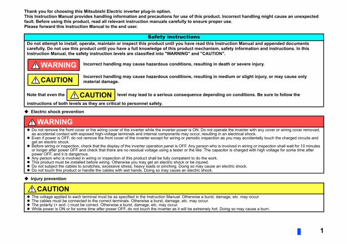
Safety instructionsDo not attempt to install, operate, maintain or inspect this product until you have read this Instruccarefully. Do not use this product until you have a full knowledge of this product mechanism, safeInstruction Manual, the safety instruction levels are classified into "WARNING" and "CAUTION".
Incorrect handling may cause hazardous conditions, resulting in death
Incorrect handling may cause hazardous conditions, resulting in mediumaterial damage.
Note that even the level may lead to a serious consequence depending on
instructions of both levels as they are critical to personnel safety.
WARNING Do not remove the front cover or the wiring cover of the inverter while the inverter power is ON. Do not operate t
as accidental contact with exposed high-voltage terminals and internal components may occur, resulting in an e Even if power is OFF, do not remove the front cover of the inverter except for wiring or periodic inspection as yo
get an electric shock. Before wiring or inspection, check that the display of the inverter operation panel is OFF. Any person who is invo
or longer after power OFF and check that there are no residual voltage using a tester or the like. The capacitor power OFF, and it is dangerous.
Any person who is involved in wiring or inspection of this product shall be fully competent to do the work. This product must be installed before wiring. Otherwise you may get an electric shock or be injured. Do not subject the cables to scratches, excessive stress, heavy loads or pinching. Doing so may cause an elect Do not touch this product or handle the cables with wet hands. Doing so may cause an electric shock.
CAUTION The voltage applied to each terminal must be as specified in the Instruction Manual. Otherwise a burst, damage The cables must be connected to the correct terminals. Otherwise a burst, damage, etc. may occur. The polarity (+ and -) must be correct. Otherwise a burst, damage, etc. may occur. While power is ON or for some time after power OFF, do not touch the inverter as it will be extremely hot. Doing
WARNING
CAUTION
CAUTION
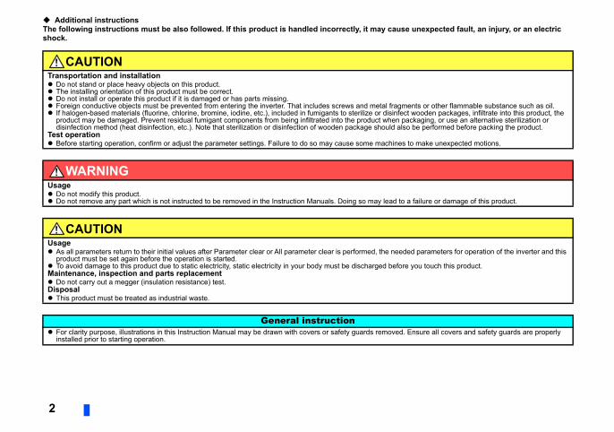
Additional instructionsThe following instructions must be also followed. If this product is handled incorrectly, it may cause unexpected fault, an injury, or an electric
ents or other flammable substance such as oil.t wooden packages, infiltrate into this product, the ckaging, or use an alternative sterilization or
o be performed before packing the product.
to make unexpected motions.
a failure or damage of this product.
ed parameters for operation of the inverter and this
you touch this product.
Ensure all covers and safety guards are properly
2
shock.
CAUTIONTransportation and installation Do not stand or place heavy objects on this product. The installing orientation of this product must be correct. Do not install or operate this product if it is damaged or has parts missing. Foreign conductive objects must be prevented from entering the inverter. That includes screws and metal fragm If halogen-based materials (fluorine, chlorine, bromine, iodine, etc.), included in fumigants to sterilize or disinfec
product may be damaged. Prevent residual fumigant components from being infiltrated into the product when padisinfection method (heat disinfection, etc.). Note that sterilization or disinfection of wooden package should als
Test operation Before starting operation, confirm or adjust the parameter settings. Failure to do so may cause some machines
WARNINGUsage Do not modify this product. Do not remove any part which is not instructed to be removed in the Instruction Manuals. Doing so may lead to
CAUTIONUsage As all parameters return to their initial values after Parameter clear or All parameter clear is performed, the need
product must be set again before the operation is started. To avoid damage to this product due to static electricity, static electricity in your body must be discharged beforeMaintenance, inspection and parts replacement Do not carry out a megger (insulation resistance) test.Disposal This product must be treated as industrial waste.
General instruction For clarity purpose, illustrations in this Instruction Manual may be drawn with covers or safety guards removed.
installed prior to starting operation.
3
6..............................................................6..............................................................7..............................................................8..............................................................9.................................................................. 9.................................................................. 9
10............................................................10............................................................11............................................................15
16............................................................16................................................................ 16................................................................ 20................................................................ 21............................................................23............................................................24
26............................................................26............................................................28................................................................ 28............................................................3179) .......................................................... 31................................................................ 36
— CONTENTS —1 PRE-OPERATION INSTRUCTIONS1.1 Unpacking and product confirmation..............................................................1.2 Component names ............................................................................................1.3 Inverter option specifications...........................................................................1.4 CC-Link version .................................................................................................
1.4.1 CC-Link Ver. 1.10 ...............................................................................................1.4.2 CC-Link Ver. 2 ....................................................................................................
2 INSTALLATION2.1 Pre-installation instructions .............................................................................2.2 Installation procedure .......................................................................................2.3 Setting of the terminating resistor selection switch ......................................
3 WIRING3.1 Connecting the CC-Link dedicated cable........................................................
3.1.1 Fabricating the connection cable ........................................................................3.1.2 Connection to the connector ...............................................................................3.1.3 Unit replacement while online .............................................................................
3.2 System configuration example.........................................................................3.3 Connection of several inverters .......................................................................
4 INVERTER SETTING4.1 Parameter list .....................................................................................................4.2 Operation mode setting ....................................................................................
4.2.1 Operation mode switching and communication startup mode (Pr.79, Pr.340)....4.3 Operation at communication error occurrence ..............................................
4.3.1 Operation selection at communication error occurrence (Pr.500 to Pr.502, Pr.74.3.2 Fault and measures ............................................................................................
4.4 Inverter reset ..................................................................................................................................................................37............................................................39................................................................ 39................................................................ 40................................................................ 41
43............................................................43............................................................44............................................................45
46............................................................46............................................................47Pr.544 = 0)............................................. 47................................................................ 50................................................................ 51................................................................ 52................................................................ 54
56............................................................56................................................................ 56................................................................ 59............................................................61................................................................ 61................................................................ 64................................................................ 68................................................................ 72
............................................................73
4
4.5 CC-Link function setting ...................................................................................4.5.1 Station number setting (Pr.542) ..........................................................................4.5.2 Baud rate setting (Pr.543) ...................................................................................4.5.3 Frequency command with sign (Pr.541) .............................................................
5 FUNCTION OVERVIEW5.1 Function block diagram ....................................................................................5.2 Output from the inverter to the network..........................................................5.3 Input to the inverter from the network.............................................................
6 I/O SIGNAL LIST6.1 CC-Link extended setting (Pr.544) ...................................................................6.2 I/O signal list ......................................................................................................
6.2.1 I/O signal when CC-Link Ver.1 one station (FR-A5NC compatible) is occupied (6.2.2 I/O signal when CC-Link Ver.1 one station is occupied (Pr.544 = 1) ..................6.2.3 I/O signal when CC-Link Ver.2 double setting is selected (Pr.544 = 12) ............6.2.4 I/O signal when CC-Link Ver.2 quadruple setting is selected (Pr.544 = 14, 24) .6.2.5 I/O signal when CC-Link Ver.2 octuple setting is selected (Pr.544 = 18, 28) .....
7 DETAILS OF INPUT AND OUTPUT SIGNALS7.1 Details of remote input and output signals.....................................................
7.1.1 Output signals (master module to inverter (FR-A8NC)) ......................................7.1.2 Input signals (inverter (FR-A8NC) to master module).........................................
7.2 Details of remote register .................................................................................7.2.1 Remote register (master module to inverter (FR-A8NC)) ...................................7.2.2 Remote register (inverter (FR-A8NC) to master module) ...................................7.2.3 Instruction codes.................................................................................................7.2.4 Monitor codes .....................................................................................................
7.3 Torque command / torque limit by CC-Link communication (only for the FR-A800 series)............................................................................
5
8 PROGRAMMING EXAMPLES 77............................................................80............................................................81............................................................82............................................................83............................................................84............................................................85............................................................86............................................................88............................................................89............................................................90
92............................................................92............................................................94............................................................96
98
8.1 Program example for reading the inverter status...........................................8.2 Program example for setting the operation mode..........................................8.3 Program example for setting the operation commands ................................8.4 Program example for monitoring the output frequency ................................8.5 Program example for parameter reading ........................................................8.6 Program example for parameter writing..........................................................8.7 Program example for setting the running frequency .....................................8.8 Program example for fault record reading......................................................8.9 Program example for resetting the inverter at inverter error ........................8.10 Instructions ........................................................................................................
9 HOW TO CHECK FOR ERROR USING THE LEDS9.1 When one inverter is connected ......................................................................9.2 When two or more inverters are connected....................................................9.3 Communication stops during operation .........................................................
APPENDIX
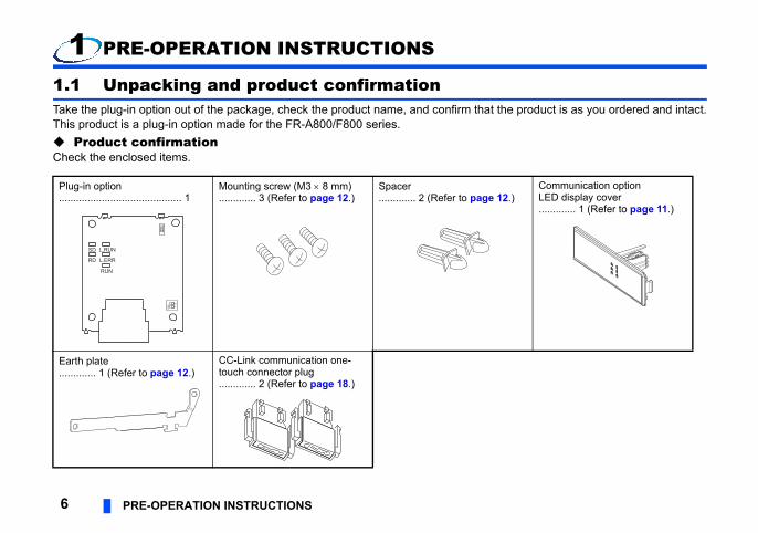
the product is as you ordered and intact.
12.)Communication option LED display cover............. 1 (Refer to page 11.)
6 PRE-OPERATION INSTRUCTIONS
1 PRE-OPERATION INSTRUCTIONS
1.1 Unpacking and product confirmationTake the plug-in option out of the package, check the product name, and confirm that This product is a plug-in option made for the FR-A800/F800 series. Product confirmationCheck the enclosed items.
Plug-in option........................................... 1
Mounting screw (M3 8 mm)............. 3 (Refer to page 12.)
Spacer............. 2 (Refer to page
Earth plate............. 1 (Refer to page 12.)
CC-Link communication one-touch connector plug............. 2 (Refer to page 18.)
SD L.RUN
RD L.ERR
RUN
O N
ON 1
2
ERATION INSTRUCTIONS 7
1
Refer to pageerting a mounting screw or 12
ith the CC-Link 21
ge the switch setting from ―
sistor. 15
12
status. 8
Rear view
(a)
(e)
PRE-OP
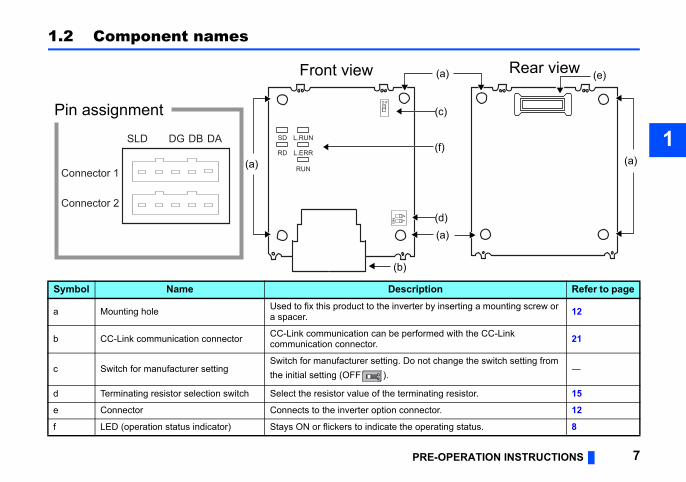
1.2 Component names
Symbol Name Description
a Mounting hole Used to fix this product to the inverter by insa spacer.
b CC-Link communication connector CC-Link communication can be performed wcommunication connector.
c Switch for manufacturer settingSwitch for manufacturer setting. Do not chanthe initial setting (OFF ).
d Terminating resistor selection switch Select the resistor value of the terminating re
e Connector Connects to the inverter option connector.
f LED (operation status indicator) Stays ON or flickers to indicate the operating
SD L.RUN
RD L.ERR
RUN
(a)
(a)
Front view
(a)
(b)
(c)
(d)
Pin assignment
ON 1
2
Connector 1
Connector 2
DASLD DG DB
O N
(f)
ON
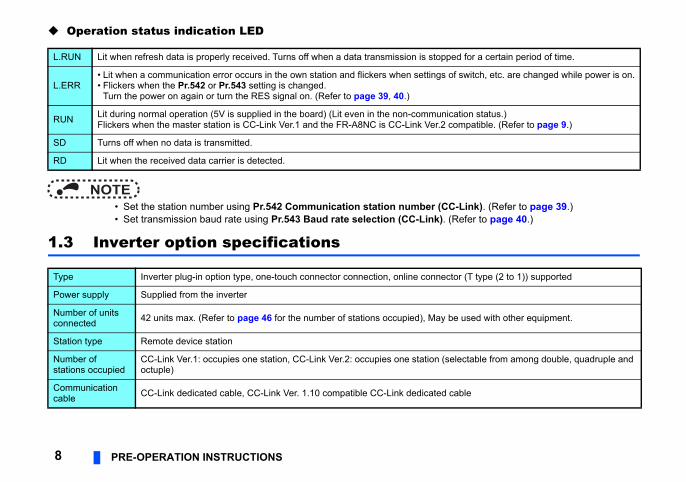
Operation status indication LED
-Link). (Refer to page 39.)Refer to page 40.)
ed for a certain period of time.
f switch, etc. are changed while power is on.
ation status.)ompatible. (Refer to page 9.)
tor (T type (2 to 1)) supported
e used with other equipment.
electable from among double, quadruple and
able
8 PRE-OPERATION INSTRUCTIONS
NOTE • Set the station number using Pr.542 Communication station number (CC • Set transmission baud rate using Pr.543 Baud rate selection (CC-Link). (
1.3 Inverter option specifications
L.RUN Lit when refresh data is properly received. Turns off when a data transmission is stopp
L.ERR• Lit when a communication error occurs in the own station and flickers when settings o• Flickers when the Pr.542 or Pr.543 setting is changed.
Turn the power on again or turn the RES signal on. (Refer to page 39, 40.)
RUN Lit during normal operation (5V is supplied in the board) (Lit even in the non-communicFlickers when the master station is CC-Link Ver.1 and the FR-A8NC is CC-Link Ver.2 c
SD Turns off when no data is transmitted.
RD Lit when the received data carrier is detected.
Type Inverter plug-in option type, one-touch connector connection, online connec
Power supply Supplied from the inverter
Number of units connected 42 units max. (Refer to page 46 for the number of stations occupied), May b
Station type Remote device station
Number of stations occupied
CC-Link Ver.1: occupies one station, CC-Link Ver.2: occupies one station (soctuple)
Communication cable CC-Link dedicated cable, CC-Link Ver. 1.10 compatible CC-Link dedicated c
ERATION INSTRUCTIONS 9
1
n changed to 20 cm or more to improve on, the conventional products are
d inter-station cable lengths of CC-Link
bles together, the maximum overall cable
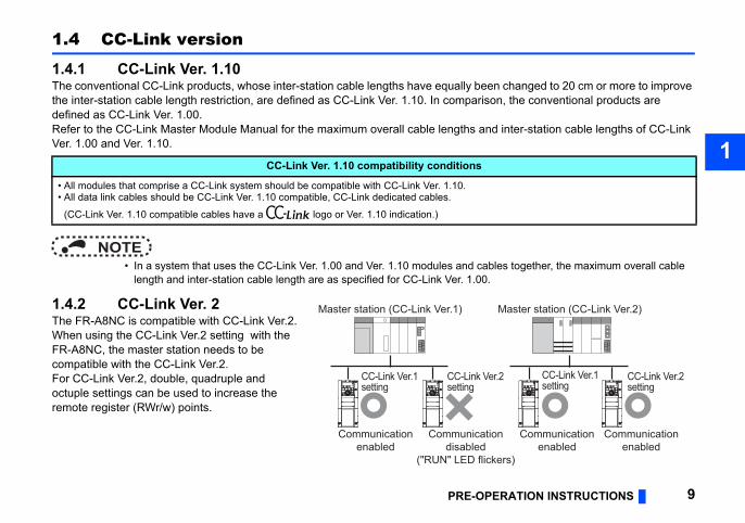
Master station (CC-Link Ver.2)
er.2 CC-Link Ver.1setting
CC-Link Ver.2setting
ion
kers)
Communicationenabled
Communicationenabled
PRE-OP
1.4 CC-Link version
1.4.1 CC-Link Ver. 1.10The conventional CC-Link products, whose inter-station cable lengths have equally beethe inter-station cable length restriction, are defined as CC-Link Ver. 1.10. In comparisdefined as CC-Link Ver. 1.00.Refer to the CC-Link Master Module Manual for the maximum overall cable lengths anVer. 1.00 and Ver. 1.10.
NOTE • In a system that uses the CC-Link Ver. 1.00 and Ver. 1.10 modules and ca
length and inter-station cable length are as specified for CC-Link Ver. 1.00.
1.4.2 CC-Link Ver. 2The FR-A8NC is compatible with CC-Link Ver.2.When using the CC-Link Ver.2 setting with the FR-A8NC, the master station needs to be compatible with the CC-Link Ver.2.For CC-Link Ver.2, double, quadruple and octuple settings can be used to increase the remote register (RWr/w) points.
CC-Link Ver. 1.10 compatibility conditions
• All modules that comprise a CC-Link system should be compatible with CC-Link Ver. 1.10.• All data link cables should be CC-Link Ver. 1.10 compatible, CC-Link dedicated cables.
(CC-Link Ver. 1.10 compatible cables have a logo or Ver. 1.10 indication.)
Master station (CC-Link Ver.1)
CC-Link Ver.1setting
CC-Link Vsetting
Communicationenabled
Communicatdisabled
("RUN" LED flic
age the inverter or this product.rged before you touch this product.
10 INSTALLATION
2 INSTALLATION
2.1 Pre-installation instructionsCheck that the inverter's input power and the control circuit power are both OFF.
CAUTION Do not install or remove this product while the inverter power is ON. Doing so may dam To avoid damage due to static electricity, static electricity in your body must be discha
INSTALLATION 11
2
tailed) of the inverter for instructions for
e inverter front cover.
f the front cover.
Cut off the tabs with a nipper, etc.
Cut off the tabs with a nipper, etc.
unication option LED display cover
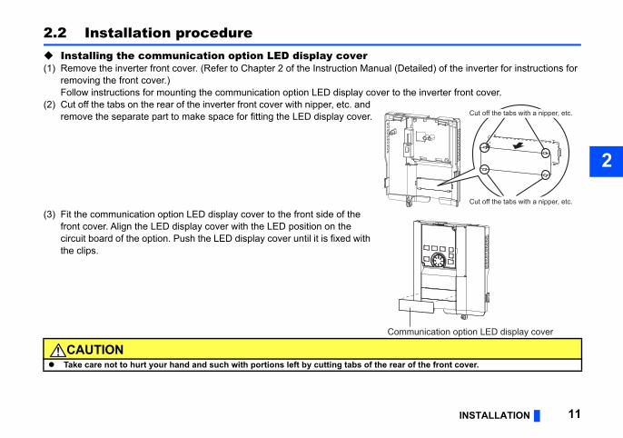
2.2 Installation procedure Installing the communication option LED display cover(1) Remove the inverter front cover. (Refer to Chapter 2 of the Instruction Manual (De
removing the front cover.)Follow instructions for mounting the communication option LED display cover to th
(2) Cut off the tabs on the rear of the inverter front cover with nipper, etc. and remove the separate part to make space for fitting the LED display cover.
(3) Fit the communication option LED display cover to the front side of the front cover. Align the LED display cover with the LED position on the circuit board of the option. Push the LED display cover until it is fixed with the clips.
CAUTION Take care not to hurt your hand and such with portions left by cutting tabs of the rear o
Comm
ries inverter, use the earthing (grounding) communication option. (For details of the
Spacer
Option connector on the inverter
Earth plateachment of this product tor 1 on the FR-A800
12 INSTALLATION
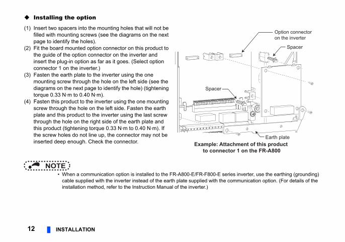
Installing the option
NOTE • When a communication option is installed to the FR-A800-E/FR-F800-E se
cable supplied with the inverter instead of the earth plate supplied with theinstallation method, refer to the Instruction Manual of the inverter.)
(1) Insert two spacers into the mounting holes that will not be filled with mounting screws (see the diagrams on the next page to identify the holes).
(2) Fit the board mounted option connector on this product to the guide of the option connector on the inverter and insert the plug-in option as far as it goes. (Select option connector 1 on the inverter.)
(3) Fasten the earth plate to the inverter using the one mounting screw through the hole on the left side (see the diagrams on the next page to identify the hole) (tightening torque 0.33 N·m to 0.40 N·m).
(4) Fasten this product to the inverter using the one mounting screw through the hole on the left side. Fasten the earth plate and this product to the inverter using the last screw through the hole on the right side of the earth plate and this product (tightening torque 0.33 N·m to 0.40 N·m). If the screw holes do not line up, the connector may not be inserted deep enough. Check the connector.
Spacer
Example: Attto connec
INSTALLATION 13
2
Spacer
Spacer
Mounting screw
Mounting screw
ector 1
s and spacers
Earth plate
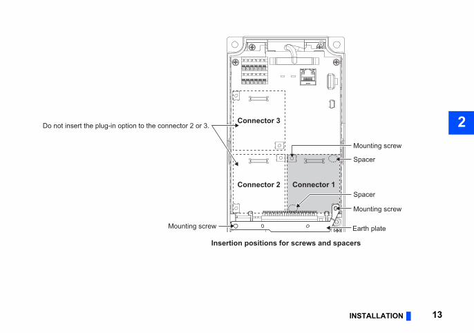
Do not insert the plug-in option to the connector 2 or 3.
ConnConnector 2
Connector 3
Insertion positions for screw
Mounting screw
not press on the parts on the option circuit
f the plug-in option.option connector 2 or 3, the protective
nnot recognize that the option is mounted
d then pull it straight out. Pressure applied
cur without it.
14 INSTALLATION
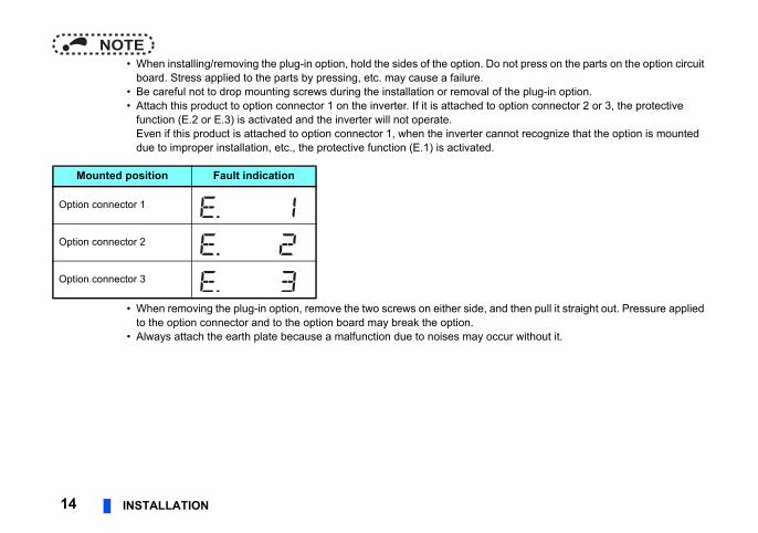
NOTE • When installing/removing the plug-in option, hold the sides of the option. Do
board. Stress applied to the parts by pressing, etc. may cause a failure. • Be careful not to drop mounting screws during the installation or removal o • Attach this product to option connector 1 on the inverter. If it is attached to
function (E.2 or E.3) is activated and the inverter will not operate.Even if this product is attached to option connector 1, when the inverter cadue to improper installation, etc., the protective function (E.1) is activated.
• When removing the plug-in option, remove the two screws on either side, anto the option connector and to the option board may break the option.
• Always attach the earth plate because a malfunction due to noises may oc
Mounted position Fault indication
Option connector 1
Option connector 2
Option connector 3
INSTALLATION 15
2
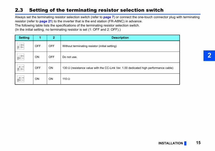
2.3 Setting of the terminating resistor selection switchAlways set the terminating resistor selection switch (refer to page 7) or connect the one-touch connector plug with terminating resistor (refer to page 21) to the inverter that is the end station (FR-A8NC) in advance.The following table lists the specifications of the terminating resistor selection switch.(In the initial setting, no terminating resistor is set (1: OFF and 2: OFF).)
Setting 1 2 Description
OFF OFF Without terminating resistor (initial setting)
ON OFF Do not use.
OFF ON 130 (resistance value with the CC-Link Ver. 1.00 dedicated high performance cable)
ON ON 110
12
ON
12
ON
12
ON
12
ON
he CC-Link dedicated cable, the -Link dedicated cables that can be used
ut notice.)
of the CC-Link Partner Association.
16 WIRING
3 WIRING
3.1 Connecting the CC-Link dedicated cable
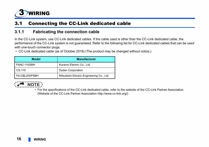
3.1.1 Fabricating the connection cableIn the CC-Link system, use CC-Link dedicated cables. If the cable used is other than tperformance of the CC-Link system is not guaranteed. Refer to the following list for CCwith one-touch connector plugs. • CC-Link dedicated cable (as of October 2018) (The product may be changed witho
NOTE • For the specifications of the CC-Link dedicated cable, refer to the website
(Website of the CC-Link Partner Association http://www.cc-link.org/)
Model Manufacturer
FANC-110SBH Kuramo Electric Co., Ltd.
CS-110 Dyden Corporation
FA-CBL200PSBH Mitsubishi Electric Engineering Co., Ltd.
WIRING 17
3
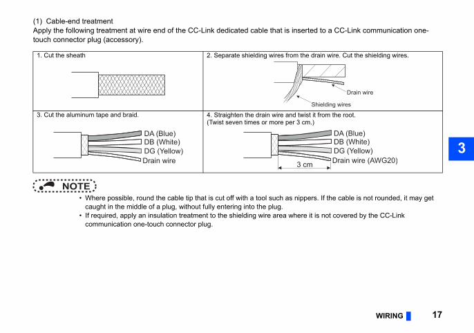
(1) Cable-end treatmentd to a CC-Link communication one-
rs. If the cable is not rounded, it may get
t is not covered by the CC-Link
drain wire. Cut the shielding wires.
it from the root.)
Drain wire
Shielding wires
DA (Blue)DB (White)DG (Yellow)Drain wire (AWG20)
Apply the following treatment at wire end of the CC-Link dedicated cable that is insertetouch connector plug (accessory).
NOTE • Where possible, round the cable tip that is cut off with a tool such as nippe
caught in the middle of a plug, without fully entering into the plug. • If required, apply an insulation treatment to the shielding wire area where i
communication one-touch connector plug.
1. Cut the sheath 2. Separate shielding wires from the
3. Cut the aluminum tape and braid. 4. Straighten the drain wire and twist(Twist seven times or more per 3 cm.
DA (Blue)DB (White)DG (Yellow)Drain wire 3 cm
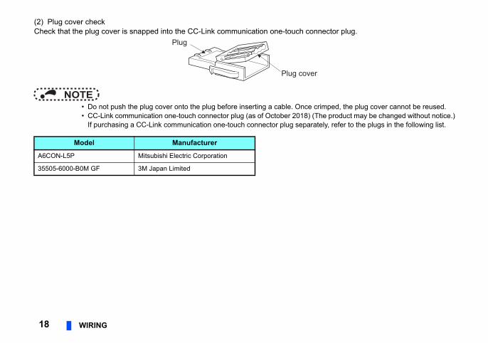
(2) Plug cover checkector plug.
imped, the plug cover cannot be reused.e product may be changed without notice.)ly, refer to the plugs in the following list.
18 WIRING
Check that the plug cover is snapped into the CC-Link communication one-touch conn
NOTE • Do not push the plug cover onto the plug before inserting a cable. Once cr • CC-Link communication one-touch connector plug (as of October 2018) (Th
If purchasing a CC-Link communication one-touch connector plug separate
Model Manufacturer
A6CON-L5P Mitsubishi Electric Corporation
35505-6000-B0M GF 3M Japan Limited
Plug
Plug cover
WIRING 19
3
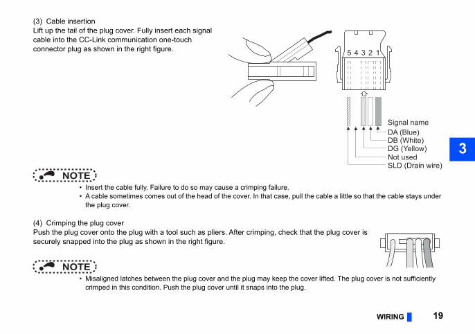
(3) Cable insertion
cable a little so that the cable stays under
the plug cover is
er lifted. The plug cover is not sufficiently
5 4 3 2 1
DA (Blue)DB (White)DG (Yellow)Not usedSLD (Drain wire)
Signal name
Lift up the tail of the plug cover. Fully insert each signal cable into the CC-Link communication one-touch connector plug as shown in the right figure.
NOTE • Insert the cable fully. Failure to do so may cause a crimping failure. • A cable sometimes comes out of the head of the cover. In that case, pull the
the plug cover.
(4) Crimping the plug coverPush the plug cover onto the plug with a tool such as pliers. After crimping, check thatsecurely snapped into the plug as shown in the right figure.
NOTE • Misaligned latches between the plug cover and the plug may keep the cov
crimped in this condition. Push the plug cover until it snaps into the plug.
n is mounted, take caution not to let the ctromagnetic noises may cause
rm, failure or malfunction.
-Linkmmunicationnnector
20 WIRING
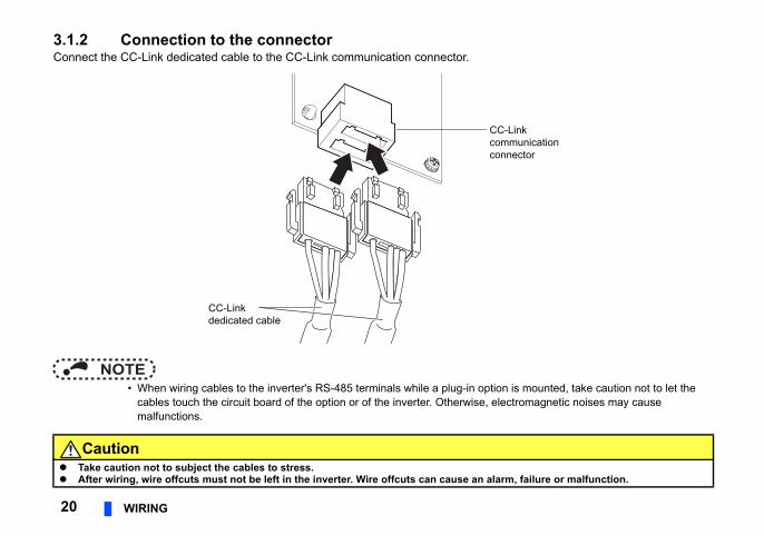
3.1.2 Connection to the connectorConnect the CC-Link dedicated cable to the CC-Link communication connector.
NOTE • When wiring cables to the inverter's RS-485 terminals while a plug-in optio
cables touch the circuit board of the option or of the inverter. Otherwise, elemalfunctions.
Caution Take caution not to subject the cables to stress. After wiring, wire offcuts must not be left in the inverter. Wire offcuts can cause an ala
CCcoco
CC-Linkdedicated cable
WIRING 21
3
. The online communication connector e online communication connector to connector 2 (back side) of the CC-Link the connectors.)unication connector of FR-A8NC at the
rminating resistor selection switches.
At the end
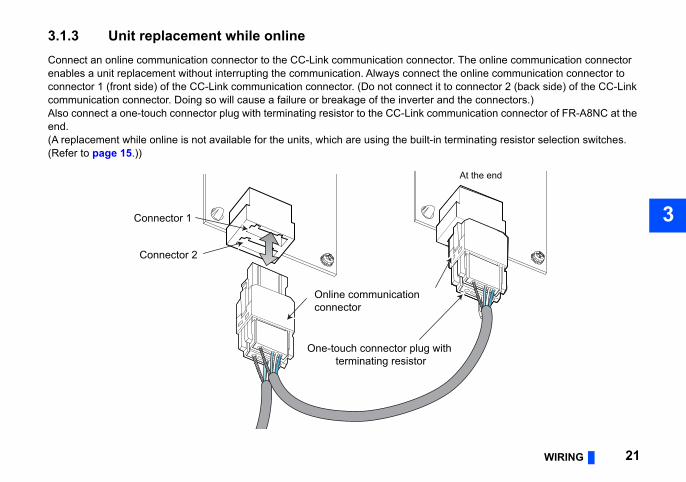
3.1.3 Unit replacement while onlineConnect an online communication connector to the CC-Link communication connectorenables a unit replacement without interrupting the communication. Always connect thconnector 1 (front side) of the CC-Link communication connector. (Do not connect it tocommunication connector. Doing so will cause a failure or breakage of the inverter andAlso connect a one-touch connector plug with terminating resistor to the CC-Link commend.(A replacement while online is not available for the units, which are using the built-in te(Refer to page 15.))
Online communicationconnector
Connector 1
One-touch connector plug withterminating resistor
Connector 2
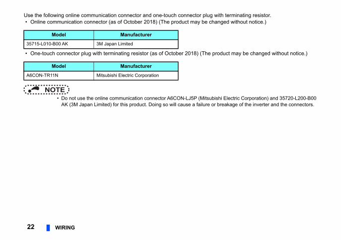
Use the following online communication connector and one-touch connector plug with terminating resistor.ed without notice.)
ct may be changed without notice.)
Electric Corporation) and 35720-L200-B00 akage of the inverter and the connectors.
22 WIRING
• Online communication connector (as of October 2018) (The product may be chang
• One-touch connector plug with terminating resistor (as of October 2018) (The produ
NOTE • Do not use the online communication connector A6CON-LJ5P (Mitsubishi
AK (3M Japan Limited) for this product. Doing so will cause a failure or bre
Model Manufacturer
35715-L010-B00 AK 3M Japan Limited
Model Manufacturer
A6CON-TR11N Mitsubishi Electric Corporation
WIRING 23
3
61QBT11" or "A1SJ61BT11" type CC-Link mmable controller CPU used as the
-Link communication connector of FR-
, the buffer memory is automatically
ries CPU)e buffer memory of the master station and
er
Motor Motor
Inverter
Powersupply
Terminatingresistor
Up to 42units can beconnectedwhen onlyinverters areconnected
Remote device station
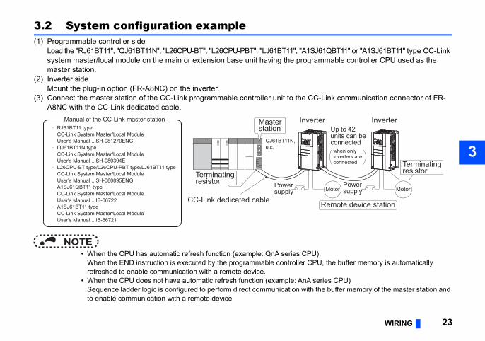
3.2 System configuration example(1) Programmable controller side
Load the "RJ61BT11", "QJ61BT11N", "L26CPU-BT", "L26CPU-PBT", "LJ61BT11", "A1SJsystem master/local module on the main or extension base unit having the programaster station.
(2) Inverter sideMount the plug-in option (FR-A8NC) on the inverter.
(3) Connect the master station of the CC-Link programmable controller unit to the CCA8NC with the CC-Link dedicated cable.
NOTE • When the CPU has automatic refresh function (example: QnA series CPU)
When the END instruction is executed by the programmable controller CPUrefreshed to enable communication with a remote device.
• When the CPU does not have automatic refresh function (example: AnA seSequence ladder logic is configured to perform direct communication with thto enable communication with a remote device
CC-Link dedicated cable
Invert
Powersupply
Manual of the CC-Link master station
QJ61BT11N,etc.
RJ61BT11 typeCC-Link System Master/Local ModuleUser's Manual ...SH-081270ENGQJ61BT11N typeCC-Link System Master/Local ModuleUser's Manual ...SH-080394EL26CPU-BT type/L26CPU-PBT type/LJ61BT11 typeCC-Link System Master/Local ModuleUser's Manual ...SH-080895ENGA1SJ61QBT11 typeCC-Link System Master/Local ModuleUser's Manual ...IB-66722A1SJ61BT11 typeCC-Link System Master/Local ModuleUser's Manual ...IB-66721
Master station
Terminatingresistor
ice stations can be controlled and eful components of an automated
esistor) in the middle units. (Refer to page 15.)
necter plug with terminating resistor. (1-OFF, 2- resistor.)
Terminating resistorselection switch ∗3
C
it and therefore the following
ss
24 WIRING
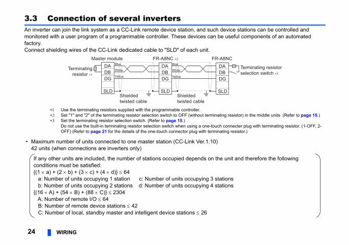
3.3 Connection of several invertersAn inverter can join the link system as a CC-Link remote device station, and such devmonitored with a user program of a programmable controller. These devices can be usfactory. Connect shielding wires of the CC-Link dedicated cable to "SLD" of each unit.
Use the terminating resistors supplied with the programmable controller. Set "1" and "2" of the terminating resistor selection switch to OFF (without terminating r Set the terminating resistor selection switch. (Refer to page 15.)
Do not use the built-in terminating resistor selection switch when using a one-touch conOFF) (Refer to page 21 for the details of the one-touch connector plug with terminating
• Maximum number of units connected to one master station (CC-Link Ver.1.10)42 units (when connections are inverters only)
DADBDG
SLD
Terminatingresistor ∗1
Master module FR-A8NC ∗2 FR-A8NDADBDG
SLD
DADBDG
SLDShieldedtwisted cable
Shieldedtwisted cable
Blue
White
Yellow
Blue
White
Yellow
If any other units are included, the number of stations occupied depends on the unconditions must be satisfied:{(1 a) + (2 b) + (3 c) + (4 d)} 64 a: Number of units occupying 1 station c: Number of units occupying 3 station b: Number of units occupying 2 stations d: Number of units occupying 4 station{(16 A) + (54 B) + (88 C)} 2304 A: Number of remote I/O 64 B: Number of remote device stations 42 C: Number of local, standby master and intelligent device stations 26
WIRING 25
3
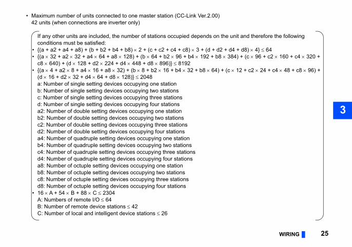
• Maximum number of units connected to one master station (CC-Link Ver.2.00)
nit and therefore the following
4 + d8) 4} 6484) + (c 96 + c2 160 + c4 320 +
12 + c2 24 + c4 48 + c8 96) +
42 units (when connections are inverter only)
If any other units are included, the number of stations occupied depends on the uconditions must be satisfied:
• {(a + a2 + a4 + a8) + (b + b2 + b4 + b8) 2 + (c + c2 + c4 + c8) 3 + (d + d2 + d • {(a 32 + a2 32 + a4 64 + a8 128) + (b 64 + b2 96 + b4 192 + b8 3
c8 640) + (d 128 + d2 224 + d4 448 + d8 896)} 8192 • {(a 4 + a2 8 + a4 16 + a8 32) + (b 8 + b2 16 + b4 32 + b8 64) + (c
(d 16 + d2 32 + d4 64 + d8 128)} 2048a: Number of single setting devices occupying one stationb: Number of single setting devices occupying two stationsc: Number of single setting devices occupying three stationsd: Number of single setting devices occupying four stationsa2: Number of double setting devices occupying one stationb2: Number of double setting devices occupying two stationsc2: Number of double setting devices occupying three stationsd2: Number of double setting devices occupying four stationsa4: Number of quadruple setting devices occupying one stationb4: Number of quadruple setting devices occupying two stationsc4: Number of quadruple setting devices occupying three stationsd4: Number of quadruple setting devices occupying four stationsa8: Number of octuple setting devices occupying one stationb8: Number of octuple setting devices occupying two stationsc8: Number of octuple setting devices occupying three stationsd8: Number of octuple setting devices occupying four stations
• 16 A + 54 B + 88 C 2304A: Numbers of remote I/O 64B: Number of remote device stations 42C: Number of local and intelligent device stations 26
licable model of the inverter, refer to the
Minimum setting
increments
Initial value
Refer to page
1 0 28
the 1 9999 59
1 0
1 0
1 0 28
1 0
1 0 38
0.1 s 0 s 31
1 0 32
26 INVERTER SETTING
4 INVERTER SETTING
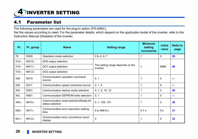
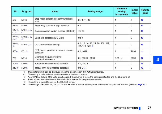
4.1 Parameter listThe following parameters are used for the plug-in option (FR-A8NC).Set the values according to need. For the parameter details, which depend on the appInstruction Manual (Detailed) of the inverter.
Pr. Pr. group Name Setting range
79 D000 Operation mode selection 0 to 4, 6, 7
313 M410 DO0 output selectionThe setting range depends oninverter.314 M411 DO1 output selection
315 M412 DO2 output selection
338 D010 Communication operation command source 0, 1
339 D011 Communication speed command source 0, 1, 2
340 D001 Communication startup mode selection 0, 1, 2, 10, 12
342 N001 Communication EEPROM write selection 0, 1
349 N010 Communication reset selection/Ready bit status selection 0, 1, 100, 101
500 N011 Communication error execution waiting time 0 to 999.8 s
501 N012 Communication error occurrence count display 0
INVERTER SETTING 27
4
cted and the LED turns off.
er supports this function. (Refer to page 73.)
1 0 32
1 0 41
1 1 39
1 0 40
12, 1 0 46
1 9999
0.01 Hz 9999 32
1 0 73
1 0 73
Minimum setting
increments
Initial value
Refer to page
Parameters which can be displayed when the plug-in option (FR-A8NC) is mounted. The setting is reflected after inverter reset or at the next power-on. "L.ERR" LED flickers if the setting is changed. If the inverter is reset, the setting is refle Refer to the Instruction Manual (Detailed) of the inverter for the parameter details. The setting is available only for the FR-A800 series. The settings of Pr.544="24, 28, or 128" and Pr.810="2" can be set only when the invert
502 N013 Stop mode selection at communication error 0 to 4, 11, 12
541 N100 Frequency command sign selection 0, 1
542, ,
N101, ,
Communication station number (CC-Link) 1 to 64
543, ,
N102, ,
Baud rate selection (CC-Link) 0 to 4
544,
N103, CC-Link extended setting 0, 1, 12, 14, 18, 24, 28, 100, 1114, 118, 128
550 D012 NET mode operation command source selection 0, 1, 9999
779 N014 Operation frequency during communication error 0 to 590 Hz, 9999
804 D400 Torque command source selection 0, 1, 3 to 6
810 H700 Torque limit input method selection 0 to 2
Pr. Pr. group Name Setting range
up mode (Pr.79, Pr.340)
instantaneous power failurecan be selected.ct the network operation mode.
erter.ation mode.etting Pr.340 "0"., Pr.340.
28 INVERTER SETTING
4.2 Operation mode setting
4.2.1 Operation mode switching and communication start Operation mode switching conditionsCheck the following before switching the operation mode. • The inverter is at a stop; • Both the STF and STR signals are off; and • The Pr.79 Operation mode selection setting is correct.
(Check the setting on the operation panel of the inverter.)
Operation mode selection at power ON and at restoration fromThe operation mode at power ON and at restoration from instantaneous power failure Set a value other than "0" in Pr.340 Communication startup mode selection to seleAfter started in network operation mode, parameter write from the network is enabled.(Refer to page 85 for a program example for parameter write.)
NOTE • Change of the Pr.340 setting is valid when powering on or resetting the inv • Pr.340 can be changed with the operation panel independently of the oper • Ensure that the communication setting of the inverter is completed before s • Refer to the Instruction Manual (Detailed) of the inverter for details of Pr.79
INVERTER SETTING 29
4
peration mode switchover
ng the External, PU, and NET operation d.,
ode fixed
een the External and Net operation mode is
e PU operation mode is disallowed.
e switching is disallowed.
ng the External, PU, and NET operation d while running.
ng the External, PU, and NET operation d.,
tion mode fixed (Forcibly switched to tion mode.)
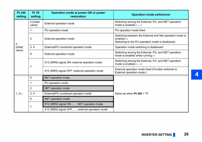
Pr.340 = "0"
Pr.340setting
Pr.79setting
Operation mode at power ON or power restoration O
0(initial value)
0 (initial value) External operation mode Switching amo
mode is enable
1 PU operation mode PU operation m
2 External operation modeSwitching betwenabled.Switching to th
3, 4 External/PU combined operation mode Operation mod
6 External operation mode Switching amomode is enable
7X12 (MRS) signal ON: external operation mode Switching amo
mode is enable
X12 (MRS) signal OFF: external operation mode External operaExternal opera
1, 2
0 NET operation mode
Same as when
1 PU operation mode
2 NET operation mode
3, 4 External/PU combined operation mode
6 NET operation mode
7X12 (MRS) signal ON........ NET operation mode
X12 (MRS) signal OFF........external operation mode
ork operation mode.verter RS-485 terminal.er failure) is set in Pr.57 Restart coasting time, een restored from an instantaneous power failure.en restored during a start command is on.
peration panel or the X65 signal.
een the PU and NET operation mode is
Pr.340 = "0"
mode fixed
Pr.340 = "0"
een the PU and NET operation mode is running.,
Pr.340 = "0"
peration mode switchover
30 INVERTER SETTING
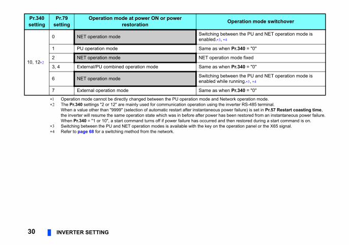
Operation mode cannot be directly changed between the PU operation mode and Netw The Pr.340 settings "2 or 12" are mainly used for communication operation using the in
When a value other than "9999" (selection of automatic restart after instantaneous powthe inverter will resume the same operation state which was in before after power has bWhen Pr.340 = "1 or 10", a start command turns off if power failure has occurred and th
Switching between the PU and NET operation modes is available with the key on the o Refer to page 68 for a switching method from the network.
10, 12
0 NET operation mode Switching betwenabled.,
1 PU operation mode Same as when
2 NET operation mode NET operation
3, 4 External/PU combined operation mode Same as when
6 NET operation mode Switching betwenabled while
7 External operation mode Same as when
Pr.340setting
Pr.79setting
Operation mode at power ON or power restoration O
INVERTER SETTING 31
4
ce
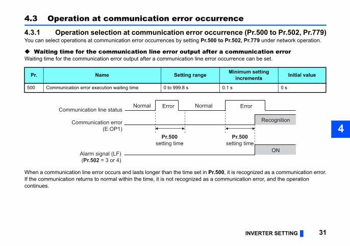
nce (Pr.500 to Pr.502, Pr.779).502, Pr.779 under network operation.
mmunication errorrrence can be set.
is recognized as a communication error.unication error, and the operation
inimum settingincrements Initial value
s 0 s
Error
Pr.500tting time
Recognition
ON
4.3 Operation at communication error occurren
4.3.1 Operation selection at communication error occurreYou can select operations at communication error occurrences by setting Pr.500 to Pr
Waiting time for the communication line error output after a coWaiting time for the communication error output after a communication line error occu
When a communication line error occurs and lasts longer than the time set in Pr.500, itIf the communication returns to normal within the time, it is not recognized as a commcontinues.
Pr. Name Setting range M
500 Communication error execution waiting time 0 to 999.8 s 0.1
Normal
se
Normal ErrorCommunication line status
Alarm signal (LF)(Pr.502 = 3 or 4)
Pr.500setting time
Communication error(E.OP1)
to clear this cumulative count.
currence count display is incremented
. When the count exceeds 65535, the
rror count is stored in EEPROM only once be the one that is last stored to EEPROM
set.
inimum setting increments Initial value
0
Description
page 33.
communication error occurs, the inverter s at the set frequency.erter operates at the frequency set before munication error occurs.
Error
Incremented by 1
32 INVERTER SETTING
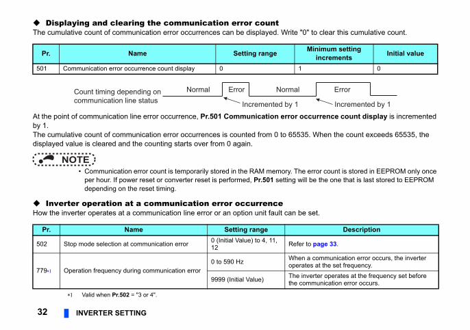
Displaying and clearing the communication error countThe cumulative count of communication error occurrences can be displayed. Write "0"
At the point of communication line error occurrence, Pr.501 Communication error ocby 1.The cumulative count of communication error occurrences is counted from 0 to 65535displayed value is cleared and the counting starts over from 0 again.
NOTE • Communication error count is temporarily stored in the RAM memory. The e
per hour. If power reset or converter reset is performed, Pr.501 setting will depending on the reset timing.
Inverter operation at a communication error occurrenceHow the inverter operates at a communication line error or an option unit fault can be
Valid when Pr.502 = "3 or 4".
Pr. Name Setting range M
501 Communication error occurrence count display 0 1
Pr. Name Setting range
502 Stop mode selection at communication error 0 (Initial Value) to 4, 11, 12 Refer to
779 Operation frequency during communication error0 to 590 Hz When a
operate
9999 (Initial Value) The invthe com
Normal ErrorCount timing depending oncommunication line status Incremented by 1
Normal
INVERTER SETTING 33
4
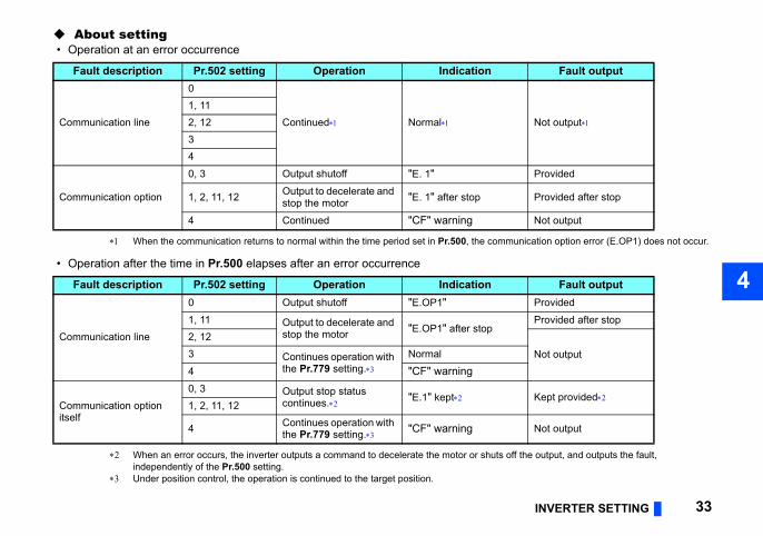
About setting
munication option error (E.OP1) does not occur.
off the output, and outputs the fault,
Fault output
Not output
Provided
Provided after stop
Not output
Fault outputProvided
Provided after stop
Not output
Kept provided
Not output
• Operation at an error occurrence
When the communication returns to normal within the time period set in Pr.500, the com
• Operation after the time in Pr.500 elapses after an error occurrence
When an error occurs, the inverter outputs a command to decelerate the motor or shutsindependently of the Pr.500 setting.
Under position control, the operation is continued to the target position.
Fault description Pr.502 setting Operation Indication
Communication line
0
Continued Normal1, 112, 1234
Communication option
0, 3 Output shutoff "E. 1"
1, 2, 11, 12 Output to decelerate and stop the motor "E. 1" after stop
4 Continued "CF" warning
Fault description Pr.502 setting Operation Indication
Communication line
0 Output shutoff "E.OP1"1, 11 Output to decelerate and
stop the motor "E.OP1" after stop2, 123 Continues operation with
the Pr.779 setting.Normal
4 "CF" warning
Communication option itself
0, 3 Output stop status continues. "E.1" kept
1, 2, 11, 12
4 Continues operation with the Pr.779 setting. "CF" warning
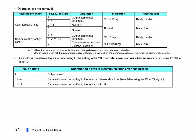
• Operation at error removal
s.n error is removed during deceleration.
time when an error occurs while Pr.502 =
Fault output
Kept provided
Not output
Kept provided
Not output
ror occurrence
able using the RT or X9 signal)
34 INVERTER SETTING
When the communication error is removed during deceleration, the motor re-accelerateUnder position control, the motor does not re-accelerates even when the communicatio
• The motor is decelerated to a stop according to the setting of Pr.111 Third deceleration"11 or 12".
Fault description Pr.502 setting Operation Indication
Communication line
0 Output stop status continues. "E.OP1" kept
1, 112, 12 Restart
Normal3Normal
4
Communication option itself
0, 3 Output stop status continues. "E. 1" kept
1, 2, 11, 12
4 Continues operation with the Pr.779 setting. "CF" warning
Pr.502 setting Operation to a stop at a communication er
0 Output shutoff
1 to 4 Deceleration stop according to the selected deceleration time (select
11, 12 Deceleration stop according to the setting of Pr.111

INVERTER SETTING 35
4
rences on the communication line. The in the communication circuit inside the
istory. (A fault record is written to the fault
fault history temporarily but not stored. back to normal, and the last fault is
s Pr.8/Pr.44/Pr.45 setting) is applied.r re-accelerates if the error is removed ore the fault occurred will be applied for ) is applied for restart. (Acceleration is not
unication line error or a communication safety stop countermeasure other than S, or X92) or press the PU stop on the
NOTE • The protective function [E.OP1 (fault data: HA1)] is activated at error occur
protective function [E.1 (fault data: HF1)] is activated at error occurrences option.
• Fault output indicates the fault (ALM) signal and fault bit output. • When the fault output setting is active, fault records are stored in the fault h
history at a fault output.) • When the fault output setting is not active, fault record is overwritten to the
After the error is removed, the fault indication is reset, changing the displaydisplayed in the fault history.
• When Pr.502 is set to "1 to 4", the normal deceleration time setting (such a • When a communication line error occurs while Pr.502 = "2 or 12", the moto
during deceleration. The operation command and the speed command befrestarting. The normal acceleration time setting (such as Pr.7/Pr.44 settingrestarted if the error is that of the option unit itself.)
CAUTION When Pr.502 = "3" and a communication line error occurs, or Pr.502 = "4" and a comm
option fault occurs, the operation continues. When setting "3 or 4" in Pr.502, provide avia communication. For example, input a signal through an external terminal (RES, MRoperation panel.
s
d) of the inverter and remove the cause of the
eration modernal operation PU operationt shutoff Output shutoff
ued Continued
ued Continued
Stop
t shutoff Output shutoff
ued Continued
ued Continued
Stop
res
move the cause of the alarm (Refer to page
option connector 1. option unit for poor contact, etc. and remove
36 INVERTER SETTING
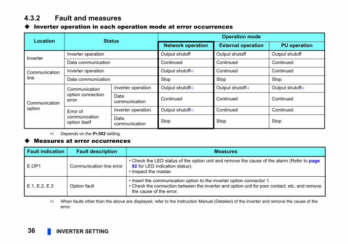
4.3.2 Fault and measures Inverter operation in each operation mode at error occurrence
Depends on the Pr.502 setting.
Measures at error occurrences
When faults other than the above are displayed, refer to the Instruction Manual (Detaileerror.
Location StatusOp
Network operation Exte
InverterInverter operation Output shutoff Outpu
Data communication Continued Contin
Communication line
Inverter operation Output shutoff Contin
Data communication Stop Stop
Communication option
Communication option connection error
Inverter operation Output shutoff Outpu
Data communication Continued Contin
Error of communication option itself
Inverter operation Output shutoff Contin
Data communication Stop Stop
Fault indication Fault description Measu
E.OP1 Communication line error• Check the LED status of the option unit and re
92 for LED indication status).• Inspect the master.
E.1, E.2, E.3 Option fault• Insert the communication option to the inverter• Check the connection between the inverter and
the cause of the error.
INVERTER SETTING 37
4
below.
the network.twork operation mode in the initial status.work operation mode again.. (Refer to page 28.)trolled for about 1 s after release of a reset
Operation mode
ork ation
External operation PU operation
Disallowed Disallowed
Allowed Allowed
Disallowed Disallowed
Allowed Allowed
Allowed Allowed
Allowed Allowed
Allowed Allowed
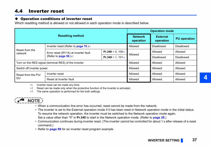
4.4 Inverter reset Operation conditions of inverter resetWhich resetting method is allowed or not allowed in each operation mode is described
Inverter reset can be made any time. Reset can be made only when the protective function of the inverter is activated. The same operation is performed for the both settings.
NOTE • When a communication line error has occurred, reset cannot be made from • The inverter is set to the External operation mode if it has been reset in Ne
To resume the network operation, the inverter must be switched to the NetSet a value other than "0" in Pr.340 to start in the Network operation mode
• Communication continues during inverter reset. (The inverter cannot be concommand.)
• Refer to page 89 for an inverter reset program example.
Resetting method Netwoper
Reset from the network
Inverter reset (Refer to page 70.) Allowed
Error reset (RY1A) at inverter fault(Refer to page 58.)
Pr.349 = 0, 100Allowed
Pr.349 = 1, 101
Turn on the RES signal (terminal RES) of the inverter Allowed
Switch off inverter power Allowed
Reset from the PU/DU
Inverter reset Allowed
Reset at inverter fault Allowed
ration mode or PU operation mode.
Function
enabled independently of operation mode.
enabled only in the network operation mode.
38 INVERTER SETTING
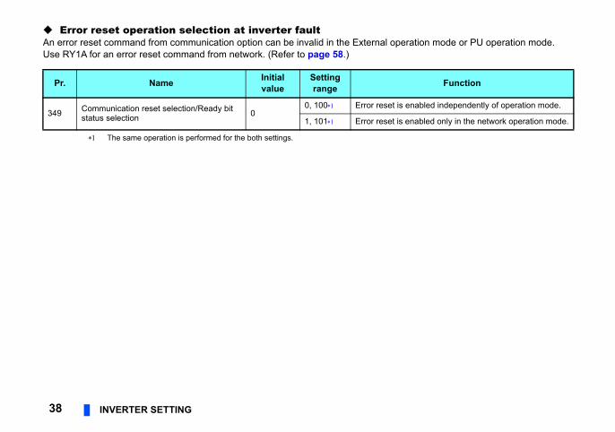
Error reset operation selection at inverter faultAn error reset command from communication option can be invalid in the External opeUse RY1A for an error reset command from network. (Refer to page 58.)
The same operation is performed for the both settings.
Pr. Name Initial value
Setting range
349 Communication reset selection/Ready bit status selection 0
0, 100 Error reset is
1, 101 Error reset is
INVERTER SETTING 39
4
inverter. Set this parameter within the
e the same station number, the
ge
No.2NC)
ice station
Inverter No.3(FR-A8NC)
Remote device station
n 03 Station 04
mber of stations connected is 4
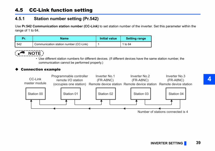
4.5 CC-Link function setting
4.5.1 Station number setting (Pr.542)Use Pr.542 Communication station number (CC-Link) to set station number of the range of 1 to 64.
NOTE • Use different station numbers for different devices. (If different devices hav
communication cannot be performed properly.)
Connection example
Pr. Name Initial value Setting ran
542 Communication station number (CC-Link) 1 1 to 64
CC-Linkmaster module
Programmable controllerremote I/O station
(occupies one station)
Station 01
Inverter No.1(FR-A8NC)
Remote device station
Inverter(FR-A8
Remote dev
Station 02 Statio
Nu
Station 00
sequence like "station number 1 - station
quence. (There is no problem with having - station number 4 - station number 2".)
again or the RES signal is turned on, the
etails of transmission speed.)
again or the RES signal is turned on, the
ansmission speed
kbps
kbps
bps
ps
bps
40 INVERTER SETTING
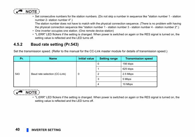
NOTE • Set consecutive numbers for the station numbers. (Do not skip a number in
number 2- station number 4".)The station number does not have to match with the physical connection sethe physical connection sequence like "station number 1 - station number 3
• One inverter occupies one station. (One remote device station) • "L.ERR" LED flickers if the setting is changed. When power is switched on
setting value is reflected and the LED turns off.
4.5.2 Baud rate setting (Pr.543)Set the transmission speed. (Refer to the manual for the CC-Link master module for d
NOTE • "L.ERR" LED flickers if the setting is changed. When power is switched on
setting value is reflected and the LED turns off.
Pr. Name Initial value Setting range Tr
543 Baud rate selection (CC-Link) 0
0 156
1 625
2 2.5 M
3 5 Mb
4 10 M
INVERTER SETTING 41
4
n be inversed to operate.
range
Actual frequency command
o 590.00 Hz
7.68 to 327.67 Hz
epends on Pr.37, Pr.144, Pr.811. 1 or 0.1 increments)
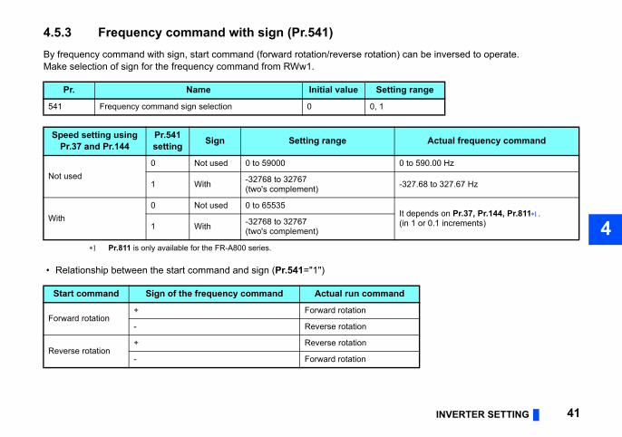
4.5.3 Frequency command with sign (Pr.541)By frequency command with sign, start command (forward rotation/reverse rotation) caMake selection of sign for the frequency command from RWw1.
Pr.811 is only available for the FR-A800 series.
• Relationship between the start command and sign (Pr.541="1")
Pr. Name Initial value Setting
541 Frequency command sign selection 0 0, 1
Speed setting using Pr.37 and Pr.144
Pr.541 setting Sign Setting range
Not used0 Not used 0 to 59000 0 t
1 With -32768 to 32767(two's complement) -32
With0 Not used 0 to 65535
It d(in1 With -32768 to 32767
(two's complement)
Start command Sign of the frequency command Actual run command
Forward rotation+ Forward rotation
- Reverse rotation
Reverse rotation+ Reverse rotation
- Forward rotation
code H01) will occur.lue other than 0 is set in Pr.544) and both
ign bit is "positive" and the set frequency is OFF the power (inverter reset).), the sign of the frequency command is not
nt from 1 r/min to 0.1 r/min. (Only for the
42 INVERTER SETTING
NOTE • When Pr.541 = 1 (with sign)
• When EEPROM write is specified with the RYE, write mode error (error • When concurrent execution of both RYD and RYE is enabled (when a va
RYD and RYE are turned on, RYD has precedence. • When power is turned on (inverter reset), the initial setting status of the s
"0 Hz". (The motor does not operate at the frequency set before turning • When set frequency is written with the instruction code of HED and HEE
changed. • Setting Pr.811 Set resolution switchover ="1 or 11" changes the increme
FR-A800 series)
FUNCTION OVERVIEW 43
5
Link: CC-Link system at intervals of 1.1 ms to
nals are used for communication
g of a faulty CC-Link station are y. (Use FROM/TO command of the efer to CC-Link master/local module
the CC-Link communication starts, link sequence program.
Input
C
Output
verter
I/O in
terfa
ce
Inve
rter C
PU
5 FUNCTION OVERVIEW
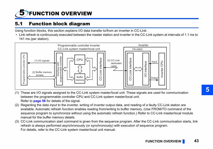
5.1 Function block diagramUsing function blocks, this section explains I/O data transfer to/from an inverter in CC- • Link refresh is continuously executed between the master station and inverter in the
141 ms (per station).
(1) These are I/O signals assigned to the CC-Link system master/local unit. These sigbetween the programmable controller CPU and CC-Link system master/local unit.Refer to page 56 for details of the signal.
(2) Regarding the data input to the inverter, writing of inverter output data, and readinavailable. Automatic refresh function enables reading from/writing to buffer memorsequence program to synchronize without using the automatic refresh function.) Rmanual for the buffer memory details.
(3) CC-Link communication start command is given from the sequence program. Afterrefresh is always performed asynchronously (or synchronously) with execution of For details, refer to the CC-Link system master/local unit manual.
(1) I/O signals CPU
Buffermemory
(2) Buffer memoryaccess
(3) CC-Link dedicatedcable
FR-A8NInProgrammable controller Inverter
CC-Link system master/local unit
Inte
rface
with
prog
ram
mab
le c
ontro
ller
Pro
gram
mab
le c
ontro
ller C
PU
CC
-Lin
k in
terfa
ce
CC
-Lin
k in
terfa
ce
re explained below.
ollable from the network in each operation
Refer to page
be monitored. 59
64, 68
68
68
68
64, 69
e checked. 65
68
70
69
44 FUNCTION OVERVIEW
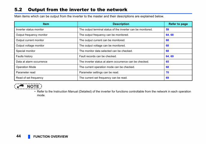
5.2 Output from the inverter to the networkMain items which can be output from the inverter to the master and their descriptions a
NOTE • Refer to the Instruction Manual (Detailed) of the inverter for functions contr
mode.
Item Description
Inverter status monitor The output terminal status of the inverter can
Output frequency monitor The output frequency can be monitored.
Output current monitor The output current can be monitored.
Output voltage monitor The output voltage can be monitored.
Special monitor The monitor data selected can be checked.
Faults history Fault records can be checked.
Data at alarm occurrence The inverter status at alarm occurrence can b
Operation Mode The current operation mode can be checked.
Parameter read Parameter settings can be read.
Read of set frequency The current set frequency can be read.
FUNCTION OVERVIEW 45
5
tions are explained below.
ollable from the network in each operation
Refer to page
56
56
ut terminals. 56
57
occurs. 58
imit). 61, 69
61, 68
68
70
l value. 70
70
70
eviation can be input 62
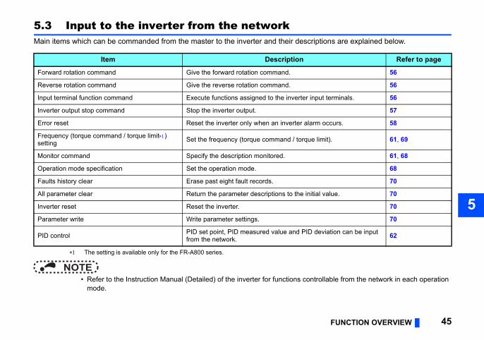
5.3 Input to the inverter from the networkMain items which can be commanded from the master to the inverter and their descrip
The setting is available only for the FR-A800 series.
NOTE • Refer to the Instruction Manual (Detailed) of the inverter for functions contr
mode.
Item Description
Forward rotation command Give the forward rotation command.
Reverse rotation command Give the reverse rotation command.
Input terminal function command Execute functions assigned to the inverter inp
Inverter output stop command Stop the inverter output.
Error reset Reset the inverter only when an inverter alarm
Frequency (torque command / torque limit) setting Set the frequency (torque command / torque l
Monitor command Specify the description monitored.
Operation mode specification Set the operation mode.
Faults history clear Erase past eight fault records.
All parameter clear Return the parameter descriptions to the initia
Inverter reset Reset the inverter.
Parameter write Write parameter settings.
PID control PID set point, PID measured value and PID dfrom the network.
f the master station must be set to double,
made.).)
r inverter reset.)
Description Refer to page
ion (FR-A5NC compatible) 47ion 50ion double 51ion quadruple 52ion octuple 54ion quadruple 52ion octuple 54ion
PLC function — ion doubleion quadrupleion octupleion octuple
46 I/O SIGNAL LIST
6 I/O SIGNAL LIST
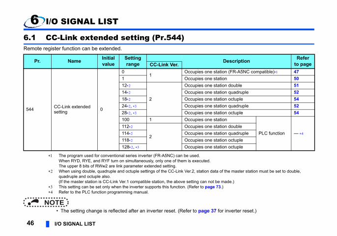
6.1 CC-Link extended setting (Pr.544)Remote register function can be extended.
The program used for conventional series inverter (FR-A5NC) can be used.When RYD, RYE, and RYF turn on simultaneously, only one of them is executed.The upper 8 bits of RWw2 are link parameter extended setting.
When using double, quadruple and octuple settings of the CC-Link Ver.2, station data oquadruple and octuple also.(If the master station is CC-Link Ver.1 compatible station, the above setting can not be
This setting can be set only when the inverter supports this function. (Refer to page 73 Refer to the PLC function programming manual.
NOTE • The setting change is reflected after an inverter reset. (Refer to page 37 fo
Pr. Name Initial value
Setting range CC-Link Ver.
544 CC-Link extended setting 0
01
Occupies one stat1 Occupies one stat12
2
Occupies one stat14 Occupies one stat18 Occupies one stat24, Occupies one stat28, Occupies one stat100 1 Occupies one stat112
2
Occupies one stat114 Occupies one stat118 Occupies one stat128, Occupies one stat
I/O SIGNAL LIST 47
6
compatible) is occupied
Signal Refer to page
unning 59
unning 59
terminal RUN function) 59
uency (terminal SU function) 59
alarm (terminal OL function) 59
eous power failure (terminal IPF
59
y detection (terminal FU
59
inal ABC1 function) 59
al ABC2 function) 59
signment function (DO0) 59
signment function (DO1) 59
6.2 I/O signal list
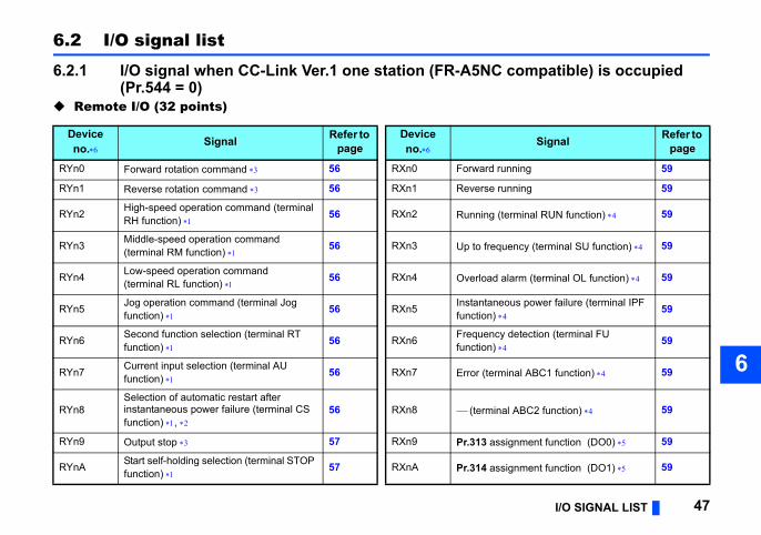
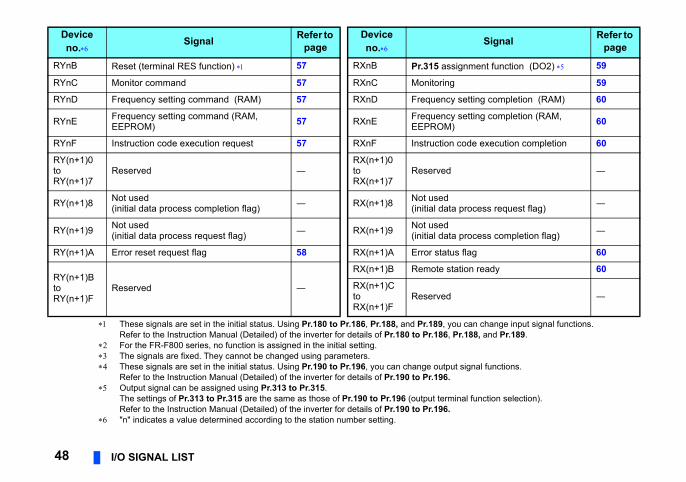
6.2.1 I/O signal when CC-Link Ver.1 one station (FR-A5NC(Pr.544 = 0)
Remote I/O (32 points)
Device no. Signal Refer to
pageDevice no.
RYn0 Forward rotation command 56 RXn0 Forward r
RYn1 Reverse rotation command 56 RXn1 Reverse r
RYn2 High-speed operation command (terminal RH function) 56 RXn2 Running (
RYn3 Middle-speed operation command (terminal RM function) 56 RXn3 Up to freq
RYn4 Low-speed operation command(terminal RL function) 56 RXn4 Overload
RYn5 Jog operation command (terminal Jog function) 56 RXn5 Instantan
function)
RYn6 Second function selection (terminal RT function) 56 RXn6 Frequenc
function)
RYn7 Current input selection (terminal AU function) 56 RXn7 Error (term
RYn8Selection of automatic restart after instantaneous power failure (terminal CS function) ,
56 RXn8 (termin
RYn9 Output stop 57 RXn9 Pr.313 as
RYnA Start self-holding selection (terminal STOP function) 57 RXnA Pr.314 as
ou can change input signal functions. Pr.188, and Pr.189.
ut signal functions.
inal function selection).
signment function (DO2) 59
g 59
y setting completion (RAM) 60
y setting completion (RAM, ) 60
code execution completion 60
―
a process request flag) ―
a process completion flag) ―
us flag 60
tation ready 60
―
Signal Refer to page
48 I/O SIGNAL LIST
These signals are set in the initial status. Using Pr.180 to Pr.186, Pr.188, and Pr.189, yRefer to the Instruction Manual (Detailed) of the inverter for details of Pr.180 to Pr.186,
For the FR-F800 series, no function is assigned in the initial setting. The signals are fixed. They cannot be changed using parameters. These signals are set in the initial status. Using Pr.190 to Pr.196, you can change outp
Refer to the Instruction Manual (Detailed) of the inverter for details of Pr.190 to Pr.196. Output signal can be assigned using Pr.313 to Pr.315.
The settings of Pr.313 to Pr.315 are the same as those of Pr.190 to Pr.196 (output termRefer to the Instruction Manual (Detailed) of the inverter for details of Pr.190 to Pr.196.
"n" indicates a value determined according to the station number setting.
RYnB Reset (terminal RES function) 57 RXnB Pr.315 as
RYnC Monitor command 57 RXnC Monitorin
RYnD Frequency setting command (RAM) 57 RXnD Frequenc
RYnE Frequency setting command (RAM, EEPROM) 57 RXnE Frequenc
EEPROM
RYnF Instruction code execution request 57 RXnF Instruction
RY(n+1)0toRY(n+1)7
Reserved ―RX(n+1)0toRX(n+1)7
Reserved
RY(n+1)8 Not used(initial data process completion flag) ― RX(n+1)8 Not used
(initial dat
RY(n+1)9 Not used(initial data process request flag) ― RX(n+1)9 Not used
(initial dat
RY(n+1)A Error reset request flag 58 RX(n+1)A Error stat
RY(n+1)BtoRY(n+1)F
Reserved ―
RX(n+1)B Remote s
RX(n+1)CtoRX(n+1)F
Reserved
Device no. Signal Refer to
pageDevice no.
I/O SIGNAL LIST 49
6
less vector control or vector control, a torque
DescriptionRefer
to page
nitor value 64
monitor value 64
de 64
ta 64
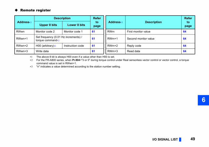
Remote register
The above 8 bit is always H00 even if a value other than H00 is set. For the FR-A800 series, when Pr.804="3 or 5" during torque control under Real sensor
command value is set in RWwn+1. "n" indicates a value determined according to the station number setting.
AddressDescription Refer
to page
AddressUpper 8 bits Lower 8 bits
RWwn Monitor code 2 Monitor code 1 61 RWrn First mo
RWwn+1 Set frequency (0.01 Hz increments) / torque command 61 RWrn+1 Second
RWwn+2 H00 (arbitrary) Instruction code 61 RWrn+2 Reply co
RWwn+3 Write data 61 RWrn+3 Read da
d (Pr.544 = 1)
less vector control or vector control, a torque
Description Refer to
pager 8 bits Lower 8 bits
nitor value 64
monitor value 64
de 2 Reply code 1 64
ta 64
50 I/O SIGNAL LIST
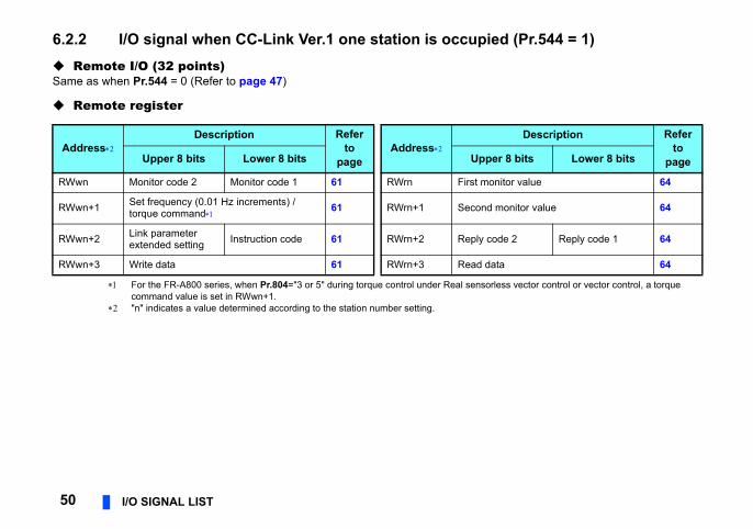
6.2.2 I/O signal when CC-Link Ver.1 one station is occupie Remote I/O (32 points)Same as when Pr.544 = 0 (Refer to page 47)
Remote register
For the FR-A800 series, when Pr.804="3 or 5" during torque control under Real sensorcommand value is set in RWwn+1.
"n" indicates a value determined according to the station number setting.
AddressDescription Refer
to page
AddressUpper 8 bits Lower 8 bits Uppe
RWwn Monitor code 2 Monitor code 1 61 RWrn First mo
RWwn+1 Set frequency (0.01 Hz increments) /torque command 61 RWrn+1 Second
RWwn+2 Link parameter extended setting Instruction code 61 RWrn+2 Reply co
RWwn+3 Write data 61 RWrn+3 Read da

I/O SIGNAL LIST 51
6
cted (Pr.544 = 12)
less vector control or vector control, a torque
Description Refer to
pager 8 bits Lower 8 bits
nitor value 64
monitor value 64
de 2 Reply code 1 64
ta 64
nitor value 64
onitor value 64
nitor value 64
nitor value 64
6.2.3 I/O signal when CC-Link Ver.2 double setting is sele Remote I/O (32 points)Same as when Pr.544 = 0 (Refer to page 47)
Remote register
For the FR-A800 series, when Pr.804="3 or 5" during torque control under Real sensorcommand value is set in RWwn+1.
"n" indicates a value determined according to the station number setting.
AddressDescription Refer
to page
AddressUpper 8 bits Lower 8 bits Uppe
RWwn Monitor code 2 Monitor code 1 61 RWrn First mo
RWwn+1 Set frequency (0.01 Hz increments) / torque command 61 RWrn+1 Second
RWwn+2 Link parameter extended setting Instruction code 61 RWrn+2 Reply co
RWwn+3 Write data 61 RWrn+3 Read da
RWwn+4 Monitor code 3 62 RWrn+4 Third mo
RWwn+5 Monitor code 4 62 RWrn+5 Fourth m
RWwn+6 Monitor code 5 62 RWrn+6 Fifth mo
RWwn+7 Monitor code 6 62 RWrn+7 Sixth mo
elected (Pr.544 = 14, 24)
Description Refer to
pageer 8 bits Lower 8 bits
onitor value 64
d monitor value 64
code 2 Reply code 1 64
data 64
onitor value 64
monitor value 64
onitor value 64
onitor value 64
history No. Fault data 64
ecord (output frequency) 65
ecord (output current) 65
ecord (output voltage) 65
ecord (energization time) 65
52 I/O SIGNAL LIST
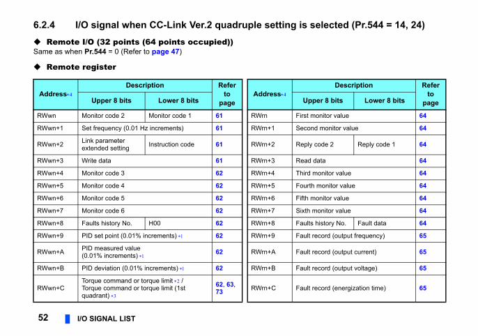
6.2.4 I/O signal when CC-Link Ver.2 quadruple setting is s Remote I/O (32 points (64 points occupied))Same as when Pr.544 = 0 (Refer to page 47)
Remote register
AddressDescription Refer
to page
AddressUpper 8 bits Lower 8 bits Upp
RWwn Monitor code 2 Monitor code 1 61 RWrn First m
RWwn+1 Set frequency (0.01 Hz increments) 61 RWrn+1 Secon
RWwn+2 Link parameter extended setting Instruction code 61 RWrn+2 Reply
RWwn+3 Write data 61 RWrn+3 Read
RWwn+4 Monitor code 3 62 RWrn+4 Third m
RWwn+5 Monitor code 4 62 RWrn+5 Fourth
RWwn+6 Monitor code 5 62 RWrn+6 Fifth m
RWwn+7 Monitor code 6 62 RWrn+7 Sixth m
RWwn+8 Faults history No. H00 62 RWrn+8 Faults
RWwn+9 PID set point (0.01% increments) 62 RWrn+9 Fault r
RWwn+A PID measured value (0.01% increments) 62 RWrn+A Fault r
RWwn+B PID deviation (0.01% increments) 62 RWrn+B Fault r
RWwn+CTorque command or torque limit /Torque command or torque limit (1st quadrant)
62, 63, 73 RWrn+C Fault r
I/O SIGNAL LIST 53
6
rter supports this function. (Refer to page 73.)
ree) ―
Description Refer to
pageer 8 bits Lower 8 bits
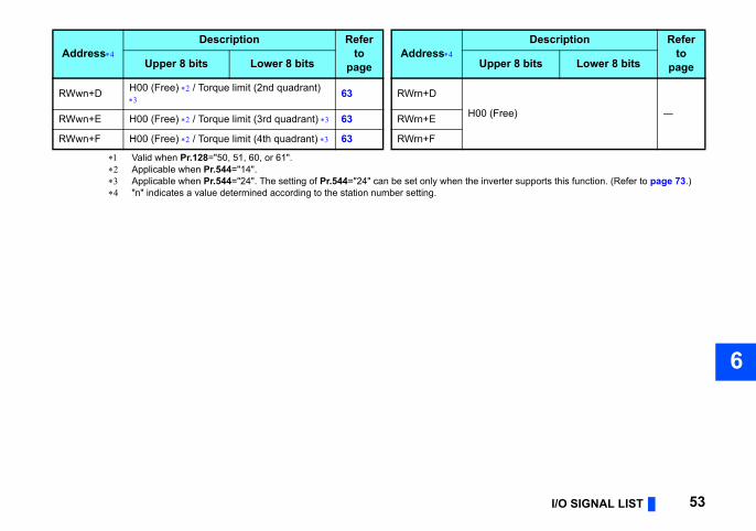
Valid when Pr.128="50, 51, 60, or 61". Applicable when Pr.544="14". Applicable when Pr.544="24". The setting of Pr.544="24" can be set only when the inve "n" indicates a value determined according to the station number setting.
RWwn+D H00 (Free) / Torque limit (2nd quadrant)
63 RWrn+D
H00 (FRWwn+E H00 (Free) / Torque limit (3rd quadrant) 63 RWrn+E
RWwn+F H00 (Free) / Torque limit (4th quadrant) 63 RWrn+F
AddressDescription Refer
to page
AddressUpper 8 bits Lower 8 bits Upp
cted (Pr.544 = 18, 28)
Description Refer to
pageer 8 bits Lower 8 bits
onitor value 64d monitor value 64
code 2 Reply code 1 64
data 64onitor value 64
monitor value 64onitor value 64onitor value 64
history No. Faults history data 64ecord (output frequency) 65ecord (output current) 65ecord (output voltage) 65
ecord (energization time) 65
ree) ―
54 I/O SIGNAL LIST
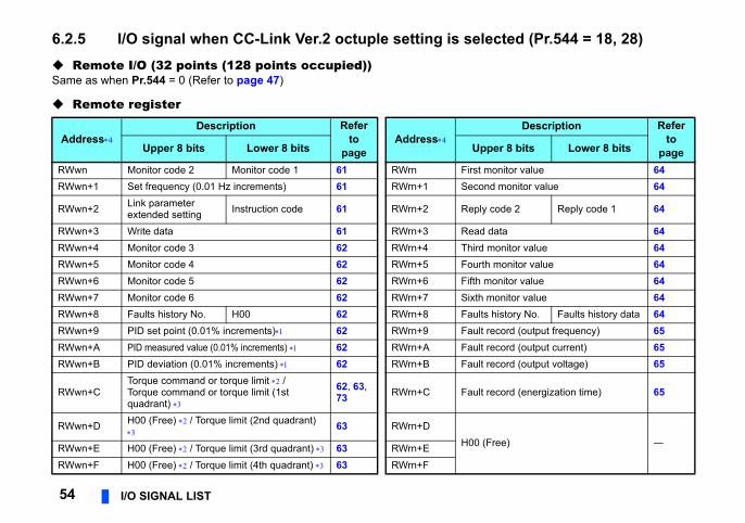
6.2.5 I/O signal when CC-Link Ver.2 octuple setting is sele Remote I/O (32 points (128 points occupied))Same as when Pr.544 = 0 (Refer to page 47)
Remote register
AddressDescription Refer
to page
AddressUpper 8 bits Lower 8 bits Upp
RWwn Monitor code 2 Monitor code 1 61 RWrn First mRWwn+1 Set frequency (0.01 Hz increments) 61 RWrn+1 Secon
RWwn+2 Link parameter extended setting Instruction code 61 RWrn+2 Reply
RWwn+3 Write data 61 RWrn+3 Read RWwn+4 Monitor code 3 62 RWrn+4 Third mRWwn+5 Monitor code 4 62 RWrn+5 FourthRWwn+6 Monitor code 5 62 RWrn+6 Fifth mRWwn+7 Monitor code 6 62 RWrn+7 Sixth mRWwn+8 Faults history No. H00 62 RWrn+8 FaultsRWwn+9 PID set point (0.01% increments) 62 RWrn+9 Fault rRWwn+A PID measured value (0.01% increments) 62 RWrn+A Fault rRWwn+B PID deviation (0.01% increments) 62 RWrn+B Fault r
RWwn+CTorque command or torque limit /Torque command or torque limit (1st quadrant)
62, 63, 73 RWrn+C Fault r
RWwn+D H00 (Free) / Torque limit (2nd quadrant)
63 RWrn+DH00 (FRWwn+E H00 (Free) / Torque limit (3rd quadrant) 63 RWrn+E
RWwn+F H00 (Free) / Torque limit (4th quadrant) 63 RWrn+F
I/O SIGNAL LIST 55
6
rter supports this function. (Refer to page 73.)
code 65
data 65
code 65
data 65
code 65
data 65
code 65
data 65
code 65
data 65
ree) ─
Description Refer to
pageer 8 bits Lower 8 bits
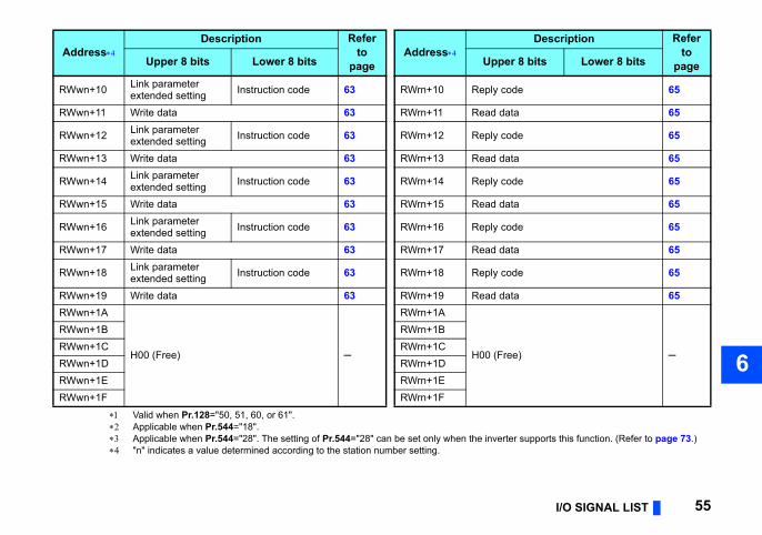
Valid when Pr.128="50, 51, 60, or 61". Applicable when Pr.544="18". Applicable when Pr.544="28". The setting of Pr.544="28" can be set only when the inve "n" indicates a value determined according to the station number setting.
RWwn+10 Link parameter extended setting Instruction code 63 RWrn+10 Reply
RWwn+11 Write data 63 RWrn+11 Read
RWwn+12 Link parameter extended setting Instruction code 63 RWrn+12 Reply
RWwn+13 Write data 63 RWrn+13 Read
RWwn+14 Link parameter extended setting Instruction code 63 RWrn+14 Reply
RWwn+15 Write data 63 RWrn+15 Read
RWwn+16 Link parameter extended setting Instruction code 63 RWrn+16 Reply
RWwn+17 Write data 63 RWrn+17 Read
RWwn+18 Link parameter extended setting Instruction code 63 RWrn+18 Reply
RWwn+19 Write data 63 RWrn+19 Read RWwn+1A
H00 (Free) ─
RWrn+1A
H00 (F
RWwn+1B RWrn+1BRWwn+1C RWrn+1CRWwn+1D RWrn+1DRWwn+1E RWrn+1ERWwn+1F RWrn+1F
AddressDescription Refer
to page
AddressUpper 8 bits Lower 8 bits Upp
LS
. are different. (Refer to the master
))
iption
t, a start command is input to the inverter.t in RY0 and RY1, a stop command is input.
, JOG, RT, AU, and CS are activated.
56 DETAILS OF INPUT AND OUTPUT SIGNALS
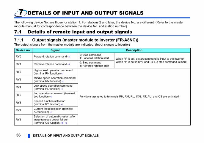
7 DETAILS OF INPUT AND OUTPUT SIGNA
The following device No. are those for station 1. For stations 2 and later, the device Nomodule manual for correspondence between the device No. and station number)
7.1 Details of remote input and output signals
7.1.1 Output signals (master module to inverter (FR-A8NCThe output signals from the master module are indicated. (Input signals to inverter)
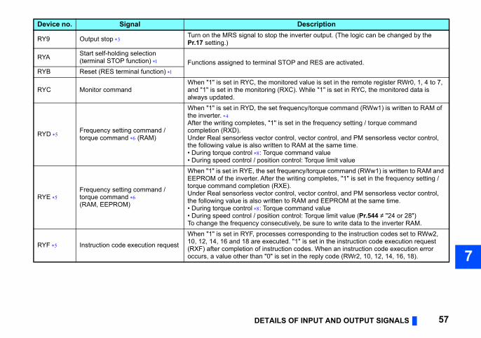
Device no. Signal Descr
RY0 Forward rotation command 0: Stop command1: Forward rotation start When "1" is se
When "1" is seRY1 Reverse rotation command 0: Stop command
1: Reverse rotation start
RY2 High-speed operation command (terminal RH function)
Functions assigned to terminals RH, RM, RL
RY3 Middle-speed operation command (terminal RM function)
RY4 Low-speed operation command (terminal RL function)
RY5 Jog operation command (terminal Jog function)
RY6 Second function selection (terminal RT function)
RY7 Current input selection (terminal AU function)
RY8Selection of automatic restart after instantaneous power failure (terminal CS function) ,
T AND OUTPUT SIGNALS 57
7
utput. (The logic can be changed by the
S are activated.
is set in the remote register RWr0, 1, 4 to 7, "1" is set in RYC, the monitored data is
que command (RWw1) is written to RAM of
equency setting / torque command
control, and PM sensorless vector control, the same time.valueue limit valueue command (RWw1) is written to RAM and pletes, "1" is set in the frequency setting /
control, and PM sensorless vector control, d EEPROM at the same time.valueue limit value (Pr.544 ≠ "24 or 28")
ure to write data to the inverter RAM.ding to the instruction codes set to RWw2, t in the instruction code execution request
hen an instruction code execution error ply code (RWr2, 10, 12, 14, 16, 18).
iption
DETAILS OF INPU
RY9 Output stop Turn on the MRS signal to stop the inverter oPr.17 setting.)
RYA Start self-holding selection (terminal STOP function) Functions assigned to terminal STOP and RE
RYB Reset (RES terminal function)
RYC Monitor commandWhen "1" is set in RYC, the monitored value and "1" is set in the monitoring (RXC). Whilealways updated.
RYD Frequency setting command / torque command (RAM)
When "1" is set in RYD, the set frequency/torthe inverter. After the writing completes, "1" is set in the frcompletion (RXD). Under Real sensorless vector control, vectorthe following value is also written to RAM at • During torque control : Torque command • During speed control / position control: Torq
RYE Frequency setting command / torque command (RAM, EEPROM)
When "1" is set in RYE, the set frequency/torqEEPROM of the inverter. After the writing comtorque command completion (RXE).Under Real sensorless vector control, vectorthe following value is also written to RAM an• During torque control : Torque command • During speed control / position control: TorqTo change the frequency consecutively, be s
RYF Instruction code execution request
When "1" is set in RYF, processes correspon10, 12, 14, 16 and 18 are executed. "1" is se(RXF) after completion of instruction codes. Woccurs, a value other than "0" is set in the re
Device no. Signal Descr
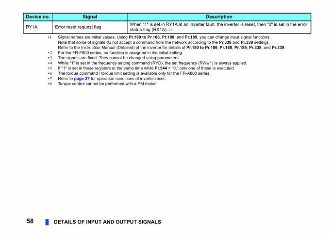
ange input signal functions.Pr.338 and Pr.339 settings. Pr.188, Pr.189, Pr.338, and Pr.339.
always applied.xecuted.
e inverter is reset, then "0" is set in the error
iption
58 DETAILS OF INPUT AND OUTPUT SIGNALS
Signal names are initial values. Using Pr.180 to Pr.186, Pr.188, and Pr.189, you can chNote that some of signals do not accept a command from the network according to the Refer to the Instruction Manual (Detailed) of the inverter for details of Pr.180 to Pr.186,
For the FR-F800 series, no function is assigned in the initial setting. The signals are fixed. They cannot be changed using parameters. While "1" is set in the frequency setting command (RYD), the set frequency (RWw1) is If "1" is set in these registers at the same time while Pr.544 = "0," only one of these is e The torque command / torque limit setting is available only for the FR-A800 series. Refer to page 37 for operation conditions of inverter reset. Torque control cannot be performed with a PM motor.
RY1A Error reset request flag When "1" is set in RY1A at an inverter fault, thstatus flag (RX1A).
Device no. Signal Descr
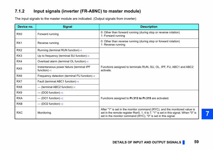
T AND OUTPUT SIGNALS 59
7
Description
during stop or reverse rotation)
during stop or forward rotation)
s RUN, SU, OL, IPF, FU, ABC1 and ABC2
o Pr.315 are activated.
mmand (RYC), and the monitored value is , 1, 4 to 7, "1" is set in this signal. When "0" is YC), "0" is set in this signal.
DETAILS OF INPU
7.1.2 Input signals (inverter (FR-A8NC) to master module)The input signals to the master module are indicated. (Output signals from inverter)
Device no. Signal
RX0 Forward running 0: Other than forward running (1: Forward running
RX1 Reverse running 0: Other than reverse running (1: Reverse running
RX2 Running (terminal RUN function)
Functions assigned to terminalactivate.
RX3 Up to frequency (terminal SU function)
RX4 Overload alarm (terminal OL function)
RX5 Instantaneous power failure (terminal IPF function)
RX6 Frequency detection (terminal FU function)
RX7 Fault (terminal ABC1 function)
RX8 ― (terminal ABC2 function)
RX9 ― (DO0 function)
Functions assigned to Pr.313 tRXA ― (DO1 function)
RXB ― (DO2 function)
RXC MonitoringAfter "1" is set in the monitor coset in the remote register Rwr0set in the monitor command (R
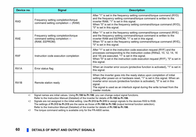
unctions.
the devices RX9 to RXB.inal function selection).
setting command/torque command (RYD) and/torque command is written to the
signal.y setting command/torque command (RYD),
setting command/torque command (RYE) and/torque command is written to the
" is set in this signal.y setting command/torque command (RYE),
code execution request (RYF) and the instruction codes (RWw2, 10, 12, 14, 16
t in this signal.n code execution request (RYF), "0" is set in
(protective function is activated), "1" is set in
ready status upon completion of initial are reset, "1" is set in this signal. When an function is activated), "0" is set in this
ck signal during the write to/read from the
Description
60 DETAILS OF INPUT AND OUTPUT SIGNALS
Signal names are initial values. Using Pr.190 to Pr.196, you can change output signal fRefer to the Instruction Manual (Detailed) of the inverter for details of Pr.190 to Pr.196.
Signals are not assigned in the initial setting. Use Pr.313 to Pr.315 to assign signals toThe settings of Pr.313 to Pr.315 are the same as those of Pr.190 to Pr.196 (output termRefer to the Instruction Manual (Detailed) of the inverter for details of Pr.190 to Pr.196.
The torque command setting is available only for the FR-A800 series.
RXD Frequency setting completion/torquecommand setting completion (RAM)
After "1" is set in the frequencyand the frequency setting comminverter RAM, "1" is set in this When "0" is set in the frequenc"0" is set in this signal.
RXEFrequency setting completion/torquecommand setting completion (RAM, EEPROM)
After "1" is set in the frequencyand the frequency setting comminverter RAM and EEPROM, "1When "0" is set in the frequenc"0" is set in this signal.
RXF Instruction code execution completion
After "1" is set in the instructionprocesses corresponding to theand 18) are executed, "1" is seWhen "0" is set in the instructiothis signal.
RX1A Error status flag When an inverter error occurs this signal.
RX1B Remote station ready
When the inverter goes into thesetting after power-on or hardwinverter error occurs (protectivesignal.The signal is used as an interlomaster module.
Device no. Signal
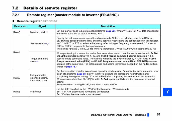
T AND OUTPUT SIGNALS 61
7
C))
n
2). When "1" is set in RYC, data of specified
t this time, whether to write to RAM or fter setting the set frequency in this register, ng of frequency is completed, "1" is set in
s). Write "59000" when setting 590.00 Hz.
vector control or vector control with Pr.544 ue command source selection = 3, 5,
the inverter either by RYD or RYE. Pr.805 mmand value (RAM, EEPROM) are also
g increments depend on the Pr.804 setting.
rewrite, Pr.read/write, error reference, error the corresponding instruction after ompleting the execution of the instruction.er eight bits are link parameter extended
200.
hen required)
DETAILS OF INPU
7.2 Details of remote register
7.2.1 Remote register (master module to inverter (FR-A8N Remote register definition
Device no. Signal Descriptio
RWw0 Monitor code1, 2 Set the monitor code to be referenced (Refer to page 7monitored items will be stored in RWr0, RWr1.
RWw1
Set frequency ,
Specify the set frequency or speed (machine speed). AEEPROM is decided with the RYD and RYE settings. Aset "1" in RYD or RYE to write the frequency. After writiRXD or RXE in response to the input command.The setting range is 0 to 590.00 Hz (0.01 Hz increment
Torque commandvalue
When performing torque control under Real sensorlessCC-Link extended setting = 0, 1, 12, and Pr.804 Torqspecify torque command value. The value is written to Torque command value (RAM) and Pr.806 Torque coupdated at the same time. The setting range and settin(Refer to page 73.)
RWw2Link parameter extended setting/ Instruction code
Set the instruction code for execution of operation modeclear, etc. (Refer to page 68) Set "1" in RYF to executecompleting the register setting. "1" is set in RXF after cWhen a value other than "0 (100)" is set in Pr.544, uppsetting.Example) When reading Pr.160, instruction code is H0
RWw3 Write dataSet the data specified by the RWw2 instruction code. (WSet "1" in RYF after setting RWw2 and this register.Set "0" when the write code is not required.
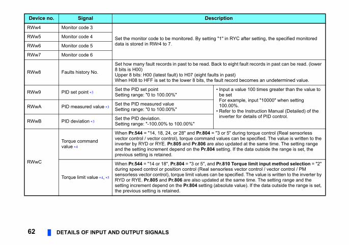
RYC after setting, the specified monitored
ight fault records in past can be read. (lower
st)cord becomes an undetermined value.
a value 100 times greater than the value to t xample, input "10000" when setting 0%.
r to the Instruction Manual (Detailed) of the ter for details of PID control.
" during torque control (Real sensorless can be specified. The value is written to the dated at the same time. The setting range . If the data outside the range is set, the
Torque limit input method selection = "2" s vector control / vector control / PM ecified. The value is written to the inverter by e same time. The setting range and the te value). If the data outside the range is set,
n
62 DETAILS OF INPUT AND OUTPUT SIGNALS
RWw4 Monitor code 3
Set the monitor code to be monitored. By setting "1" in data is stored in RWr4 to 7.
RWw5 Monitor code 4
RWw6 Monitor code 5
RWw7 Monitor code 6
RWw8 Faults history No.
Set how many fault records in past to be read. Back to e8 bits is H00)Upper 8 bits: H00 (latest fault) to H07 (eight faults in paWhen H08 to HFF is set to the lower 8 bits, the fault re
RWw9 PID set point Set the PID set pointSetting range: "0 to 100.00%"
• Inputbe seFor e100.0
• Refeinver
RWwA PID measured value Set the PID measured valueSetting range: "0 to 100.00%"
RWwB PID deviation Set the PID deviation.Setting range: "-100.00% to 100.00%"
RWwC
Torque command value
When Pr.544 = "14, 18, 24, or 28" and Pr.804 = "3 or 5vector control / vector control), torque command valuesinverter by RYD or RYE. Pr.805 and Pr.806 are also upand the setting increment depend on the Pr.804 settingprevious setting is retained.
Torque limit value ,
When Pr.544 = "14 or 18", Pr.804 = "3 or 5", and Pr.810during speed control or position control (Real sensorlessensorless vector control), torque limit values can be spRYD or RYE. Pr.805 and Pr.806 are also updated at thsetting increment depend on the Pr.804 setting (absoluthe previous setting is retained.
Device no. Signal Descriptio
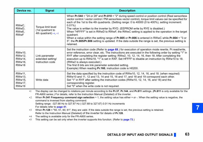
T AND OUTPUT SIGNALS 63
7
Pr.811 settings. (Pr.811 is only available for the
or -. When the setting value is negative, the
revious setting is retained.
.)
d control or position control (Real sensorless ntrol), torque limit values can be specified for o 40000 (0 to 400%), setting increment:
write by RYE is disabled.)etting is applied to the operation in the target
06 is entered in RWwC while Pr.804 = "3 or side the range is set, the previous setting is
on of operation mode rewrite, Pr.read/write, ecuted in the following order by setting "1" in 2, 14, 16, then 18. After completing the o disable an instruction by RWw10 to 18.
200.
0, 12, 14, 16, and 18. (when required)18 and 19 correspond each other.10, 12, 14, 16, and 18) and the
n
DETAILS OF INPU
The display can be changed to rotations per minute according to the Pr.37, Pr.144, andFR-A800 series.) For details, refer to the Instruction Manual (Detailed) of the inverter.
When Pr.541 Frequency command sign selection = 1, the setting value has either + command is inversed from starting command.Setting range: -327.68 Hz to 327.67 Hz (-327.68 to 327.67) 0.01 Hz incrementsFor details refer to page 41.
When Pr.128 = "50, 51, 60, 61", they are valid. If the data outside the range is set, the pRefer to the Instruction Manual (Detailed) of the inverter for details of Pr.128.
The setting is available only for the FR-A800 series. This setting can be set only when the inverter supports this function. (Refer to page 73
RWwC, RWwD, RWwE, RWwF
Torque limit level(1st quadrant to 4th quadrant) ,
When Pr.544 = "24 or 28" and Pr.810 = "2" during speevector control / vector control / PM sensorless vector coeach of the 1st to the 4th quadrants. (Setting range: 0 t0.01%)The value is written to the inverter by RYD. (EEPROM When "HFFFF" is set in RWwD to RWwF, the RWwC squadrant.When a value within the setting range of Pr.805 or Pr.85", the Pr.805/Pr.806 setting is updated. If the data outretained.
RWw10, RWw12, RWw14, RWw16, RWw18
Link parameter extended setting/ Instruction code
Set the instruction code (Refer to page 68.) for executierror reference, error clear, etc. The instructions are exRYF after completing the register setting: RWw2, 10, 1execution up to RWw18, "1" is set in RXF. Set HFFFF t(RWw2 is always executed.)The first 8 bits are link parameter extended setting.Example) When reading Pr.160, instruction code is H0
RWw11, RWw13, RWw15, RWw17, RWw19
Write data
Set the data specified by the instruction code of RWw1RWw10 and 11, 12 and 13, 14 and 15, 16 and 17, and Set "1" in RYF after setting the instruction codes (RWwcorresponding register.Set "0" when the write code is not required.
Device no. Signal Descriptio
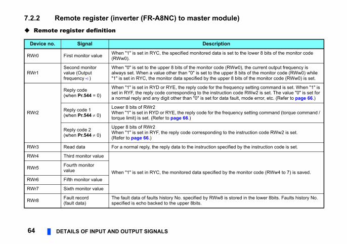
le)
et to the lower 8 bits of the monitor code
Ww0), the current output frequency is er 8 bits of the monitor code (RWw0) while r 8 bits of the monitor code (RWw0) is set.
quency setting command is set. When "1" is n code RWw2 is set. The value "0" is set for fault, mode error, etc. (Refer to page 66.)
quency setting command (torque command /
the instruction code RWw2 is set.
ified by the instruction code is set.
the monitor code (RWw4 to 7) is saved.
stored in the lower 8bits. Faults history No.
64 DETAILS OF INPUT AND OUTPUT SIGNALS
7.2.2 Remote register (inverter (FR-A8NC) to master modu Remote register definition
Device no. Signal Description
RWr0 First monitor value When "1" is set in RYC, the specified monitored data is s(RWw0).
RWr1Second monitor value (Output frequency )
When "0" is set to the upper 8 bits of the monitor code (Ralways set. When a value other than "0" is set to the upp"1" is set in RYC, the monitor data specified by the uppe
RWr2
Reply code(when Pr.544 = 0)
When "1" is set in RYD or RYE, the reply code for the freset in RYF, the reply code corresponding to the instructioa normal reply and any digit other than "0" is set for data
Reply code 1(when Pr.544 0)
Lower 8 bits of RWr2When "1" is set in RYD or RYE, the reply code for the fretorque limit) is set. (Refer to page 66.)
Reply code 2(when Pr.544 0)
Upper 8 bits of RWr2When "1" is set in RYF, the reply code corresponding to (Refer to page 66.)
RWr3 Read data For a normal reply, the reply data to the instruction spec
RWr4 Third monitor value
When "1" is set in RYC, the monitored data specified byRWr5 Fourth monitor
value
RWr6 Fifth monitor value
RWr7 Sixth monitor value
RWr8 Fault record(fault data)
The fault data of faults history No. specified by RWw8 isspecified is echo backed to the upper 8bits.
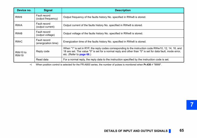
T AND OUTPUT SIGNALS 65
7
w8 is stored.
8 is stored.
8 is stored.
w8 is stored.
the instruction code RWw10, 12, 14, 16, and her than "0" is set for data fault, mode error,
ified by the instruction code is set.
itored when Pr.430 ≠ "9999".
DETAILS OF INPU
RWr9 Fault record(output frequency) Output frequency of the faults history No. specified in RW
RWrA Fault record(output current) Output current of the faults history No. specified in RWw
RWrB Fault record(output voltage) Output voltage of the faults history No. specified in RWw
RWrC Fault record(energization time) Energization time of the faults history No. specified in RW
RWr10 to RWr19
Reply codeWhen "1" is set in RYF, the reply codes corresponding to18 are set. The value "0" is set for a normal reply and otetc. (Refer to page 66.)
Read data For a normal reply, the reply data to the instruction spec
When position control is selected for the FR-A800 series, the number of pulses is mon
Device no. Signal Description
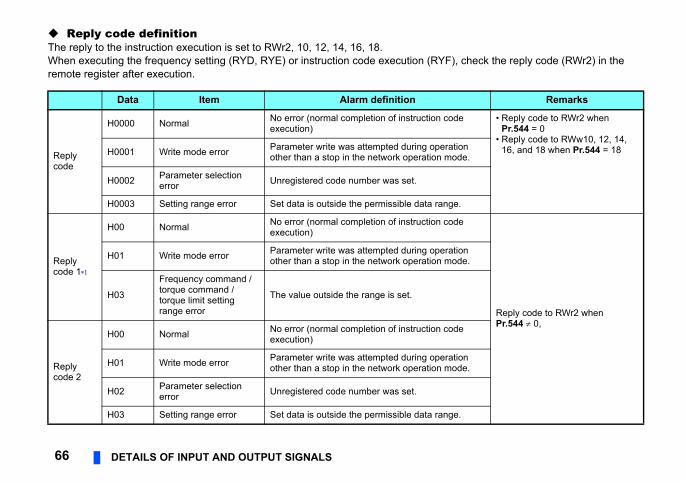
), check the reply code (RWr2) in the
Remarks
de • Reply code to RWr2 when Pr.544 = 0
• Reply code to RWw10, 12, 14, 16, and 18 when Pr.544 = 18tion
ode.
e.
de
Reply code to RWr2 when Pr.544 0,
tion ode.
de
tion ode.
e.
66 DETAILS OF INPUT AND OUTPUT SIGNALS
Reply code definitionThe reply to the instruction execution is set to RWr2, 10, 12, 14, 16, 18.When executing the frequency setting (RYD, RYE) or instruction code execution (RYFremote register after execution.
Data Item Alarm definition
Reply code
H0000 Normal No error (normal completion of instruction coexecution)
H0001 Write mode error Parameter write was attempted during operaother than a stop in the network operation m
H0002 Parameter selection error Unregistered code number was set.
H0003 Setting range error Set data is outside the permissible data rang
Reply code 1
H00 Normal No error (normal completion of instruction coexecution)
H01 Write mode error Parameter write was attempted during operaother than a stop in the network operation m
H03
Frequency command / torque command / torque limit setting range error
The value outside the range is set.
Replycode 2
H00 Normal No error (normal completion of instruction coexecution)
H01 Write mode error Parameter write was attempted during operaother than a stop in the network operation m
H02 Parameter selection error Unregistered code number was set.
H03 Setting range error Set data is outside the permissible data rang
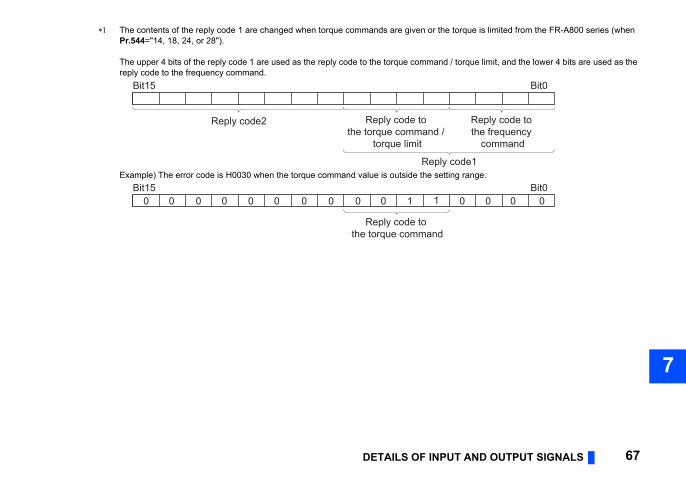
T AND OUTPUT SIGNALS 67
7
The contents of the reply code 1 are changed when torque commands are given or the torque is limited from the FR-A800 series (when
/ torque limit, and the lower 4 bits are used as the
ng range.
Bit0
code1
Reply code to the frequency
command
Bit00 0 0 0
DETAILS OF INPU
Pr.544="14, 18, 24, or 28").
The upper 4 bits of the reply code 1 are used as the reply code to the torque command reply code to the frequency command.
Example) The error code is H0030 when the torque command value is outside the setti
Bit15
Reply code2
Reply
Reply code to the torque command /
torque limit
Bit15
Reply code to the torque command
0 0 0 0 0 0 0 0 0 0 1 1
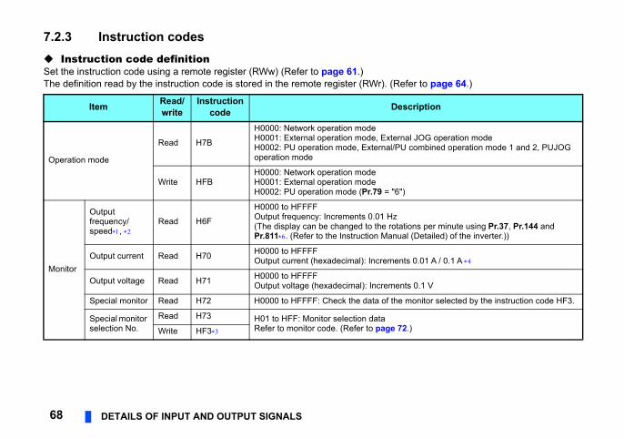
r to page 64.)
ription
l JOG operation modecombined operation mode 1 and 2, PUJOG
ns per minute using Pr.37, Pr.144 and (Detailed) of the inverter.))
0.01 A / 0.1 A
0.1 V
onitor selected by the instruction code HF3.
)
68 DETAILS OF INPUT AND OUTPUT SIGNALS
7.2.3 Instruction codes Instruction code definitionSet the instruction code using a remote register (RWw) (Refer to page 61.)The definition read by the instruction code is stored in the remote register (RWr). (Refe
Item Read/write
Instructioncode Desc
Operation mode
Read H7B
H0000: Network operation modeH0001: External operation mode, ExternaH0002: PU operation mode, External/PU operation mode
Write HFBH0000: Network operation modeH0001: External operation modeH0002: PU operation mode (Pr.79 = "6")
Monitor
Output frequency/speed,
Read H6F
H0000 to HFFFFOutput frequency: Increments 0.01 Hz(The display can be changed to the rotatioPr.811. (Refer to the Instruction Manual
Output current Read H70 H0000 to HFFFFOutput current (hexadecimal): Increments
Output voltage Read H71 H0000 to HFFFFOutput voltage (hexadecimal): Increments
Special monitor Read H72 H0000 to HFFFF: Check the data of the m
Special monitor selection No.
Read H73 H01 to HFF: Monitor selection dataRefer to monitor code. (Refer to page 72.Write HF3
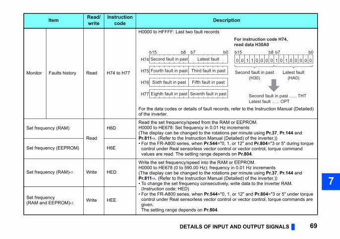
T AND OUTPUT SIGNALS 69
7
ds, refer to the Instruction Manual (Detailed)
AM or EEPROM.z incrementsns per minute using Pr.37, Pr.144 and (Detailed) of the inverter.)), 1, or 12" and Pr.804="3 or 5" during torque trol or vector control, torque command
nds on Pr.804.
M or EEPROM.cy in 0.01 Hz incrementsns per minute using Pr.37, Pr.144 and (Detailed) of the inverter.))ly, write data to the inverter RAM.
, 1, or 12" and Pr.804="3 or 5" under torque trol or vector control, torque commands are
ription
b0
t
t
st
For instruction code H74, read data H30A0
Second fault in past ...... THTLatest fault ...... OPT
0 10 1 0 0 0 0 0 0 00001 1
b15 b8 b7 b0
Latest fault(HA0)
Second fault in past(H30)
DETAILS OF INPU
Monitor Faults history Read H74 to H77
H0000 to HFFFF: Last two fault records
For the data codes or details of fault recorof the inverter.
Set frequency (RAM)
Read
H6DRead the set frequency/speed from the RH0000 to HE678: Set frequency in 0.01 H(The display can be changed to the rotatioPr.811. (Refer to the Instruction Manual • For the FR-A800 series, when Pr.544="0
control under Real sensorless vector convalues are read. The setting range depe
Set frequency (EEPROM) H6E
Set frequency (RAM) Write HED
Write the set frequency/speed into the RAH0000 to HE678 (0 to 590.00 Hz): frequen(The display can be changed to the rotatioPr.811. (Refer to the Instruction Manual • To change the set frequency consecutive
(Instruction code: HED)• For the FR-A800 series, when Pr.544="0
control under Real sensorless vector congiven.The setting range depends on Pr.804.
Set frequency(RAM and EEPROM) Write HEE
Item Read/write
Instructioncode Desc
b15 b8 b7Latest faultSecond fault in past
Third fault in pasFourth fault in past
Fifth fault in pasSixth fault in past
Seventh fault in paEighth fault in past
H74
H75
H76
H77
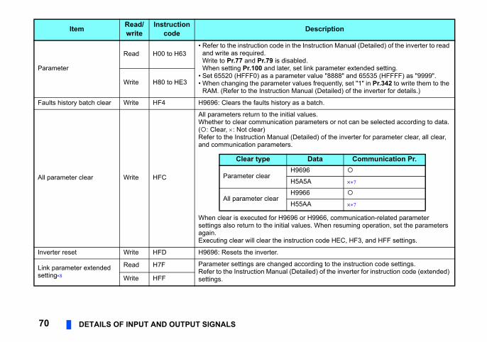
ction Manual (Detailed) of the inverter to read
arameter extended setting.e "8888" and 65535 (HFFFF) as "9999".quently, set "1" in Pr.342 to write them to the etailed) of the inverter for details.)
h.
ers or not can be selected according to data.
of the inverter for parameter clear, all clear,
66, communication-related parameter hen resuming operation, set the parameters
de HEC, HF3, and HFF settings.
g to the instruction code settings.of the inverter for instruction code (extended)
ription
Communication Pr.
70 DETAILS OF INPUT AND OUTPUT SIGNALS
Parameter
Read H00 to H63• Refer to the instruction code in the Instru
and write as required.Write to Pr.77 and Pr.79 is disabled.When setting Pr.100 and later, set link p
• Set 65520 (HFFF0) as a parameter valu• When changing the parameter values fre
RAM. (Refer to the Instruction Manual (DWrite H80 to HE3
Faults history batch clear Write HF4 H9696: Clears the faults history as a batc
All parameter clear Write HFC
All parameters return to the initial values.Whether to clear communication paramet(: Clear, : Not clear)Refer to the Instruction Manual (Detailed)and communication parameters.
When clear is executed for H9696 or H99settings also return to the initial values. Wagain.Executing clear will clear the instruction co
Inverter reset Write HFD H9696: Resets the inverter.
Link parameter extended setting
Read H7F Parameter settings are changed accordinRefer to the Instruction Manual (Detailed) settings.Write HFF
Item Read/write
Instructioncode Desc
Clear type Data
Parameter clearH9696
H5A5A
All parameter clearH9966
H55AA
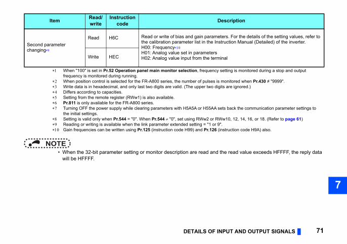
T AND OUTPUT SIGNALS 71
7
read value exceeds HFFFF, the reply data
. For the details of the setting values, refer to tion Manual (Detailed) of the inverter.
ng is monitored during a stop and output
itored when Pr.430 ≠ "9999".re ignored.)
ack the communication parameter settings to
0, 12, 14, 16, or 18. (Refer to page 61)
uction code H9A) also.
ription
DETAILS OF INPU
NOTE • When the 32-bit parameter setting or monitor description are read and the
will be HFFFF.
Second parameter changing
Read H6C Read or write of bias and gain parametersthe calibration parameter list in the InstrucH00: FrequencyH01: Analog value set in parametersH02: Analog value input from the terminalWrite HEC
When "100" is set in Pr.52 Operation panel main monitor selection, frequency settifrequency is monitored during running.
When position control is selected for the FR-A800 series, the number of pulses is mon Write data is in hexadecimal, and only last two digits are valid. (The upper two digits a Differs according to capacities. Setting from the remote register (RWw1) is also available. Pr.811 is only available for the FR-A800 series. Turning OFF the power supply while clearing parameters with H5A5A or H55AA sets b
the initial settings. Setting is valid only when Pr.544 = "0". When Pr.544 "0", set using RWw2 or RWw1 Reading or writing is available when the link parameter extended setting = "1 or 9". Gain frequencies can be written using Pr.125 (instruction code H99) and Pr.126 (instr
Item Read/write
Instructioncode Desc
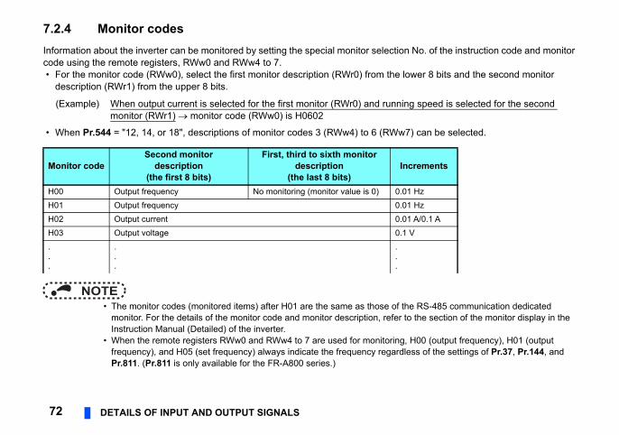
No. of the instruction code and monitor
wer 8 bits and the second monitor
) can be selected.
e RS-485 communication dedicated o the section of the monitor display in the
H00 (output frequency), H01 (output ess of the settings of Pr.37, Pr.144, and
crements
1 Hz1 Hz1 A/0.1 A V
g speed is selected for the second
72 DETAILS OF INPUT AND OUTPUT SIGNALS
7.2.4 Monitor codesInformation about the inverter can be monitored by setting the special monitor selectioncode using the remote registers, RWw0 and RWw4 to 7. • For the monitor code (RWw0), select the first monitor description (RWr0) from the lo
description (RWr1) from the upper 8 bits.
• When Pr.544 = "12, 14, or 18", descriptions of monitor codes 3 (RWw4) to 6 (RWw7
NOTE • The monitor codes (monitored items) after H01 are the same as those of th
monitor. For the details of the monitor code and monitor description, refer tInstruction Manual (Detailed) of the inverter.
• When the remote registers RWw0 and RWw4 to 7 are used for monitoring,frequency), and H05 (set frequency) always indicate the frequency regardlPr.811. (Pr.811 is only available for the FR-A800 series.)
Monitor codeSecond monitor
description(the first 8 bits)
First, third to sixth monitor description
(the last 8 bits)In
H00 Output frequency No monitoring (monitor value is 0) 0.0H01 Output frequency 0.0H02 Output current 0.0H03 Output voltage 0.1...
.
.
.
.
.
.
(Example) When output current is selected for the first monitor (RWr0) and runninmonitor (RWr1) monitor code (RWw0) is H0602
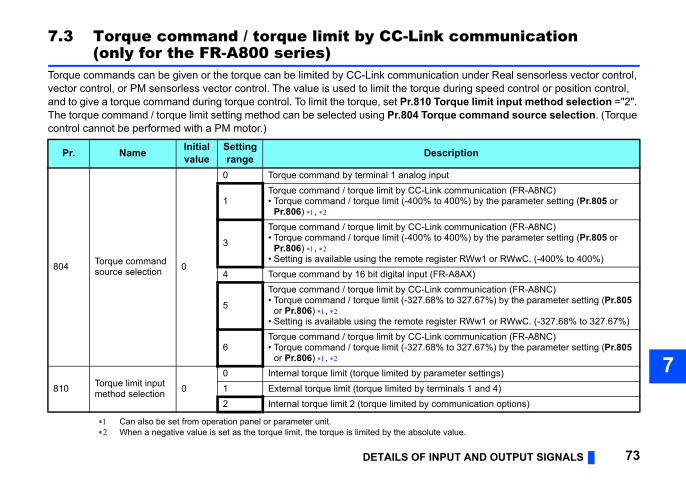
T AND OUTPUT SIGNALS 73
7
ommunication
n under Real sensorless vector control, ring speed control or position control,
que limit input method selection ="2". e command source selection. (Torque
lue.
iption
mmunication (FR-A8NC)00%) by the parameter setting (Pr.805 or
mmunication (FR-A8NC)00%) by the parameter setting (Pr.805 or
r RWw1 or RWwC. (-400% to 400%)8AX)mmunication (FR-A8NC) 327.67%) by the parameter setting (Pr.805
r RWw1 or RWwC. (-327.68% to 327.67%)mmunication (FR-A8NC) 327.67%) by the parameter setting (Pr.805
eter settings)als 1 and 4)unication options)
DETAILS OF INPU
7.3 Torque command / torque limit by CC-Link c(only for the FR-A800 series)
Torque commands can be given or the torque can be limited by CC-Link communicatiovector control, or PM sensorless vector control. The value is used to limit the torque duand to give a torque command during torque control. To limit the torque, set Pr.810 TorThe torque command / torque limit setting method can be selected using Pr.804 Torqucontrol cannot be performed with a PM motor.)
Can also be set from operation panel or parameter unit. When a negative value is set as the torque limit, the torque is limited by the absolute va
Pr. Name Initial value
Setting range Descr
804 Torque command source selection 0
0 Torque command by terminal 1 analog input
1Torque command / torque limit by CC-Link co• Torque command / torque limit (-400% to 4
Pr.806) ,
3
Torque command / torque limit by CC-Link co• Torque command / torque limit (-400% to 4
Pr.806) , • Setting is available using the remote registe
4 Torque command by 16 bit digital input (FR-A
5
Torque command / torque limit by CC-Link co• Torque command / torque limit (-327.68% to
or Pr.806) , • Setting is available using the remote registe
6Torque command / torque limit by CC-Link co• Torque command / torque limit (-327.68% to
or Pr.806) ,
810 Torque limit input method selection 0
0 Internal torque limit (torque limited by param1 External torque limit (torque limited by termin2 Internal torque limit 2 (torque limited by comm
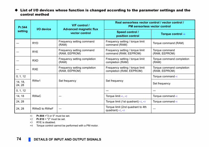
parameter settings and the
vector control / vector control / nsorless vector control
/ l Torque control
e limit Torque command (RAM)
e limit M)
Torque command (RAM, EEPROM)
e limit Torque command completion (RAM)
e limit M)
Torque command completion (RAM, EEPROM)
Torque command
Set frequency
―
Torque command
t) , Torque command
t to 4th ―
74 DETAILS OF INPUT AND OUTPUT SIGNALS
List of I/O devices whose function is changed according to thecontrol method
Pr.804 ="3 or 5" must be set. Pr.810 = "2" must be set. RYE is disabled. Torque control cannot be performed with a PM motor.
Pr.544 setting I/O device
V/F control / Advanced magnetic flux
vector control
Real sensorlessPM se
Speed controlposition contro
― RYD Frequency setting command (RAM)
Frequency setting / torqucommand (RAM)
― RYE Frequency setting command (RAM, EEPROM)
Frequency setting / torqucommand (RAM, EEPRO
― RXD Frequency setting completion (RAM)
Frequency setting / torqucompletion (RAM)
― RXE Frequency setting completion (RAM, EEPROM)
Frequency setting / torqucompletion (RAM, EEPRO
0, 1, 12RWw1 Set frequency Set frequency14, 18,
24, 28
0, 1, 12
RWwC ―
―
14, 18 Torque limit ,
24, 28 Torque limit (1st quadran
24, 28 RWwD to RWwF ― Torque limit (2nd quadranquadrant) ,
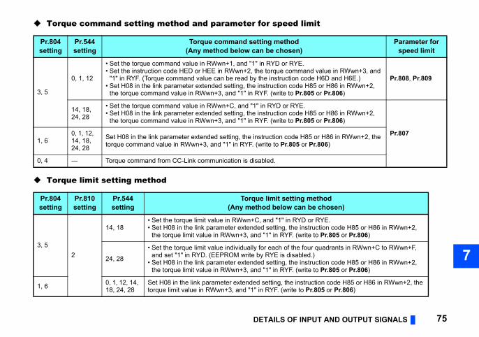
T AND OUTPUT SIGNALS 75
7
it
Parameter forspeed limit
value in RWwn+3, and H6D and H6E.) or H86 in RWwn+2,
or Pr.806)
Pr.808, Pr.809
or H86 in RWwn+2, or Pr.806)
Pr.807or H86 in RWwn+2, the .806)
thod chosen)
RYE.ction code H85 or H86 in RWwn+2, o Pr.805 or Pr.806)
quadrants in RWwn+C to RWwn+F,
ction code H85 or H86 in RWwn+2, o Pr.805 or Pr.806)
tion code H85 or H86 in RWwn+2, the 805 or Pr.806)
DETAILS OF INPU
Torque command setting method and parameter for speed lim
Torque limit setting method
Pr.804setting
Pr.544setting
Torque command setting method(Any method below can be chosen)
3, 5
0, 1, 12
• Set the torque command value in RWwn+1, and "1" in RYD or RYE.• Set the instruction code HED or HEE in RWwn+2, the torque command
"1" in RYF. (Torque command value can be read by the instruction code• Set H08 in the link parameter extended setting, the instruction code H85
the torque command value in RWwn+3, and "1" in RYF. (write to Pr.805
14, 18, 24, 28
• Set the torque command value in RWwn+C, and "1" in RYD or RYE.• Set H08 in the link parameter extended setting, the instruction code H85
the torque command value in RWwn+3, and "1" in RYF. (write to Pr.805
1, 60, 1, 12, 14, 18, 24, 28
Set H08 in the link parameter extended setting, the instruction code H85 torque command value in RWwn+3, and "1" in RYF. (write to Pr.805 or Pr
0, 4 ― Torque command from CC-Link communication is disabled.
Pr.804setting
Pr.810setting
Pr.544setting
Torque limit setting me(Any method below can be
3, 52
14, 18• Set the torque limit value in RWwn+C, and "1" in RYD or • Set H08 in the link parameter extended setting, the instru
the torque limit value in RWwn+3, and "1" in RYF. (write t
24, 28
• Set the torque limit value individually for each of the four and set "1" in RYD. (EEPROM write by RYE is disabled.)
• Set H08 in the link parameter extended setting, the instruthe torque limit value in RWwn+3, and "1" in RYF. (write t
1, 6 0, 1, 12, 14, 18, 24, 28
Set H08 in the link parameter extended setting, the instructorque limit value in RWwn+3, and "1" in RYF. (write to Pr.
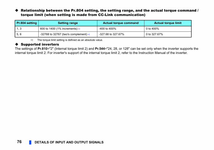
the actual torque command / n)
set only when the inverter supports the struction Manual of the inverter.
Actual torque limit
0 to 400%
0 to 327.67%
76 DETAILS OF INPUT AND OUTPUT SIGNALS
Relationship between the Pr.804 setting, the setting range, andtorque limit (when setting is made from CC-Link communicatio
The torque limit setting is defined as an absolute value.
Supported invertersThe settings of Pr.810="2" (Internal torque limit 2) and Pr.544="24, 28, or 128" can beinternal torque limit 2. For inverter's support of the internal torque limit 2, refer to the In
Pr.804 setting Setting range Actual torque command
1, 3 600 to 1400 (1% increments) -400 to 400%
5, 6 -32768 to 32767 (two's complement) -327.68 to 327.67%
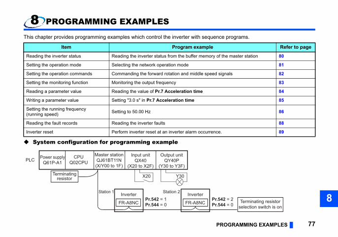
OGRAMMING EXAMPLES 77
8
e programs.
Refer to page
the master station 80
81
gnals 82
83
84
85
86
88
89
2 = 24 = 0
Terminating resistorselection switch is on
PR
8 PROGRAMMING EXAMPLES
This chapter provides programming examples which control the inverter with sequenc
System configuration for programming example
Item Program example
Reading the inverter status Reading the inverter status from the buffer memory of
Setting the operation mode Selecting the network operation mode
Setting the operation commands Commanding the forward rotation and middle speed si
Setting the monitoring function Monitoring the output frequency
Reading a parameter value Reading the value of Pr.7 Acceleration time
Writing a parameter value Setting "3.0 s" in Pr.7 Acceleration time
Setting the running frequency(running speed) Setting to 50.00 Hz
Reading the fault records Reading the inverter faults
Inverter reset Perform inverter reset at an inverter alarm occurrence.
Power supplyQ61P-A1
CPUQ02CPU
Master stationQJ61BT11N(X/Y00 to 1F)
Input unitQX40
(X20 to X2F)
Output unitQY40P
(Y30 to Y3F)
Station 1 InverterPr.542 = 1Pr.544 = 0
Pr.54Pr.54FR-A8NC
Station 2 Inverter
FR-A8NC
PLC
X20 Y30Terminatingresistor
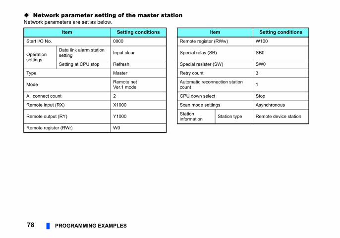
Network parameter setting of the master station
Setting conditions
w) W100
SB0
SW0
3
on station 1
Stop
Asynchronous
tion type Remote device station
78 PROGRAMMING EXAMPLES
Network parameters are set as below.
Item Setting conditions Item
Start I/O No. 0000 Remote register (RW
Operationsettings
Data link alarm station setting Input clear Special relay (SB)
Setting at CPU stop Refresh Special resister (SW)
Type Master Retry count
Mode Remote netVer.1 mode
Automatic reconnecticount
All connect count 2 CPU down select
Remote input (RX) X1000 Scan mode settings
Remote output (RY) Y1000 Stationinformation Sta
Remote register (RWr) W0
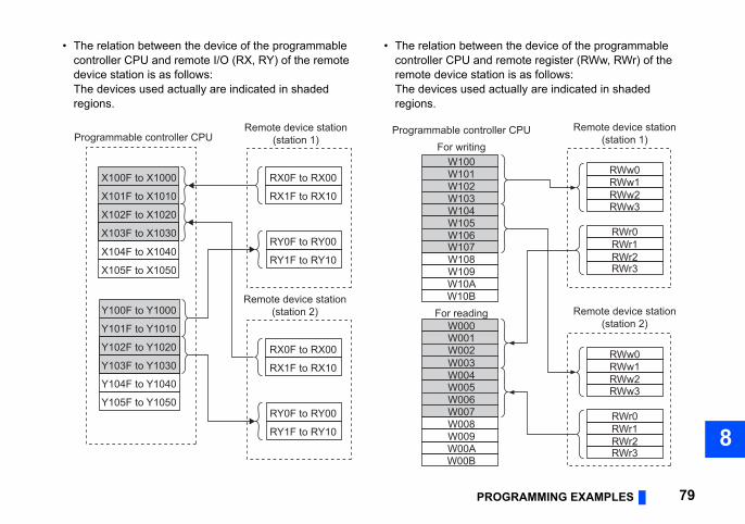
OGRAMMING EXAMPLES 79
8
en the device of the programmable remote register (RWw, RWr) of the ion is as follows:actually are indicated in shaded
RWw0
ller CPU Remote device station(station 1)
RWw1RWw2RWw3
RWr0RWr1RWr2RWr3
RWw0
Remote device station(station 2)
RWw1RWw2RWw3
RWr0RWr1RWr2RWr3
PR
• The relation between the device of the programmable controller CPU and remote I/O (RX, RY) of the remote device station is as follows:The devices used actually are indicated in shaded regions.
• The relation betwecontroller CPU andremote device statThe devices used regions.
RX0F to RX00
RX1F to RX10
X100F to X1000
X101F to X1010
X102F to X1020
X103F to X1030
Y100F to Y1000
Y101F to Y1010
Y102F to Y1020
Y103F to Y1030
Programmable controller CPURemote device station
(station 1)
RY0F to RY00
RY1F to RY10X104F to X1040
X105F to X1050
Y104F to Y1040
Y105F to Y1050
RX0F to RX00
RX1F to RX10
Remote device station(station 2)
RY0F to RY00
RY1F to RY10
W100
Programmable controFor writing
W101W102W103W104W105W106W107
W000For reading
W001W002W003W004
W009W00AW00B
W108W109W10AW10B
W005W006W007W008
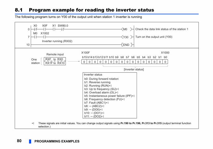
tatusg
, Pr.313 to Pr.315 (output terminal function
ck the data link status of the station 1
n on the output unit (Y00)
0 0 0 0 0
X1000b4 b3 b2 b1 b0
us]
80 PROGRAMMING EXAMPLES
8.1 Program example for reading the inverter sThe following program turns on Y00 of the output unit when station 1 inverter is runnin
These signals are initial values. You can change output signals using Pr.190 to Pr.196selection.)
M0
Y30
END
CheX0
0
7
10
X0F X1
M0 X1002Tur
Inverter running (RX02)
SW80.0
0 0 0 0 0 0 00 0 0 0b15X100F
b14 b13 b12 b11 b10 b9 b8 b7 b6 b5
[Inverter stat
Inverter statusb0: During forward rotationb1: Reverse runningb2: Running (RUN)∗1b3: Up to frequency (SU)∗1b4: Overload alarm (OL)∗1b5: Instantaneous power failure (IPF)∗1b6: Frequency detection (FU)∗1b7: Fault (ABC1)∗1
b9: ─ (DO0)∗1b10: ─ (DO1)∗1b11: ─ (DO2)∗1
b8: ─ (ABC2)∗1
RXF RX0RX1F
to RX10
Onestation
Remote input
to
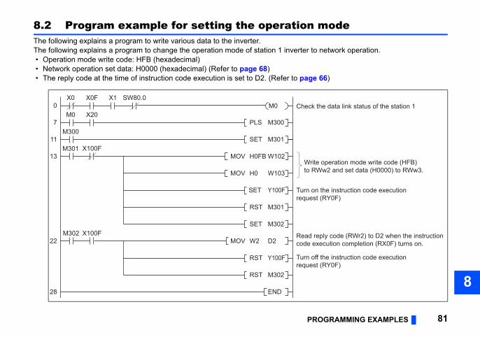
OGRAMMING EXAMPLES 81
8
mode
network operation.
66)
e operation mode write code (HFB)Ww2 and set data (H0000) to RWw3.
ff the instruction code executiont (RY0F)
n the instruction code executiont (RY0F)
eply code (RWr2) to D2 when the instructionxecution completion (RX0F) turns on.
the data link status of the station 1
PR
8.2 Program example for setting the operation The following explains a program to write various data to the inverter.The following explains a program to change the operation mode of station 1 inverter to • Operation mode write code: HFB (hexadecimal) • Network operation set data: H0000 (hexadecimal) (Refer to page 68) • The reply code at the time of instruction code execution is set to D2. (Refer to page
SET M301
PLS M300
M301
MOV W2 D2
MOV H0FB W102Writto R
SET Y100F
Turn oreques
0
13
M0 X20
X100F
M300
RST M301
SET M302M302
22
RST Y100F
RST M302
END28
7
11
Turn oreques
MOV H0 W103
Read rcode e
X0 X0F X1
X100F
CheckSW80.0
M0
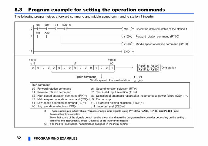
commandsn 1 inverter
orward rotation command (RY00)
iddle speed operation command (RY03)
heck the data link status of the station 1
ONOFF
RY0F to RY00RY1F to RY10
One station
er instantaneous power failure (CS)∗1, ∗2
P)∗1
to Pr.186, Pr.188, and Pr.189 (input
mable controller depending on the setting.
82 PROGRAMMING EXAMPLES
8.3 Program example for setting the operation The following program gives a forward command and middle speed command to statio
F
X0 X0F X1
M0 X200
7
11
M
Y1000
END
Y1003
CM0SW80.0
0 0 0 0 000 0 0 0 0 0 1 0 0 1b15 b0
Y100F Y1000b7
[Run command]Forward rotation
1:0:
Run commandb0 : Forward rotation command
b5 : Jog operation selection (JOG)∗1
b1 : Reverse rotation commandb6 : Second function selection (RT)∗1
b2 : High-speed operation command (RH)∗1b7 : Terminal 4 input selection (AU)∗1
b3 : Middle-speed operation command (RM)∗1b8 : Selection of automatic restart aft
b10 : Start self-holding selection (STOb11 : Inverter reset (RES)∗1
b4 : Low-speed operation command (RL)∗1b9 : Output stop
Middle speed
These signals are initial values. You can change input signals using Pr.180terminal function selection).Note that some of the signals do not receive a command from the program(Refer to the Instruction Manual (Detailed) of the inverter for details.)
For the FR-F800 series, no function is assigned in the initial setting.
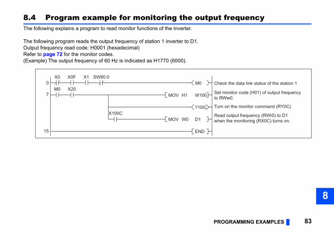
OGRAMMING EXAMPLES 83
8
frequency
t monitor code (H01) of output frequencyRWw0.
rn on the monitor command (RY0C)
ad output frequency (RWr0) to D1en the monitoring (RX0C) turns on.
eck the data link status of the station 1
PR
8.4 Program example for monitoring the outputThe following explains a program to read monitor functions of the inverter.
The following program reads the output frequency of station 1 inverter to D1.Output frequency read code: H0001 (hexadecimal)Refer to page 72 for the monitor codes.(Example) The output frequency of 60 Hz is indicated as H1770 (6000).
X0 X0F X1
Seto MOV H1 W100
Tu
MOV W0 D1Rewh
END15
7
0
X100C
M0 X20
Y100C
ChM0SW80.0
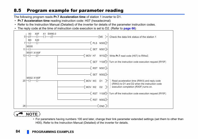
r instruction codes. 66)
extended settings (set them to other than
e (H07) to RWw2.
on code execution request (RY0F)
on code execution request (RY0F)
n time (RWr3) and reply code D2 when the instruction codetion (RX0F) turns on.
k status of the station 1
84 PROGRAMMING EXAMPLES
8.5 Program example for parameter readingThe following program reads Pr.7 Acceleration time of station 1 inverter to D1. • Pr.7 Acceleration time reading instruction code: H07 (hexadecimal) • Refer to the Instruction Manual (Detailed) of the inverter for details of the paramete • The reply code at the time of instruction code execution is set to D2. (Refer to page
NOTE • For parameters having numbers 100 and later, change their link parameter
H00). Refer to the Instruction Manual (Detailed) of the inverter for details.
SET M301
PLS M300
M301
MOV W3 D1
MOV H7 W102 Write Pr.7 read cod
RST M301
Turn off the instructi
0
7
11
13
20
28
M0 X20
X100F
X100F
X0 X0F X1
M300
SET M302
SET Y100F
M302
MOV W2 D2
RST Y100F
RST M302
END
Turn on the instructi
Read acceleratio(RWr2) to D1 andexecution comple
Check the data linM0SW80.0
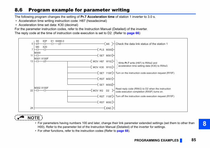
OGRAMMING EXAMPLES 85
8
rter to 3.0 s.
verter.)
extended settings (set them to other than inverter for settings.
87) to RWw2 andetting data (K30) to RWw3.
n code execution request (RY0F)
n code execution request (RY0F)
r2) to D2 when the instructionletion (RX0F) turns on.
k status of the station 1
PR
8.6 Program example for parameter writingThe following program changes the setting of Pr.7 Acceleration time of station 1 inve • Acceleration time writing instruction code: H87 (hexadecimal) • Acceleration time set data: K30 (decimal)For the parameter instruction codes, refer to the Instruction Manual (Detailed) of the inThe reply code at the time of instruction code execution is set to D2. (Refer to page 66
NOTE • For parameters having numbers 100 and later, change their link parameter
H00). Refer to the parameter list of the Instruction Manual (Detailed) of the • For other functions, refer to the instruction codes (Refer to page 68).
SET M301
PLS M300
MOV W2 D2
MOV H87 W102 Write Pr.7 write (Hacceleration time s
SET Y100F
Turn off the instructio
0
7
11
13
22
28
M0 X20
X100FM301
X0 X0F X1
X100F
M300
SET M302M302
RST Y100F
RST M302
END
Turn on the instructio
MOV K30 W103
RST M301
Read reply code (RWcode execution comp
Check the data linM0SW80.0
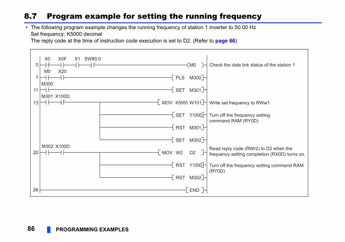
equency to 50.00 Hz
66)
t frequency to RWw1.
the frequency setting command RAM
the frequency settingd RAM (RY0D)
ply code (RWr2) to D2 when they setting completion (RX0D) turns on.
e data link status of the station 1
86 PROGRAMMING EXAMPLES
8.7 Program example for setting the running fr • The following program example changes the running frequency of station 1 inverter
Set frequency: K5000 decimalThe reply code at the time of instruction code execution is set to D2. (Refer to page
SET M301
PLS M300
M301
MOV W2 D2
MOV K5000 W101 Write se
SET Y100D
Turn off (RY0D)
0
7
11
13
20
26
RST M301
M0 X20
X100D
X0 X0F X1
M302 X100D
M300
SET M302
RST Y100D
RST M302
END
Turn off comman
Read refrequenc
Check thM0SW80.0
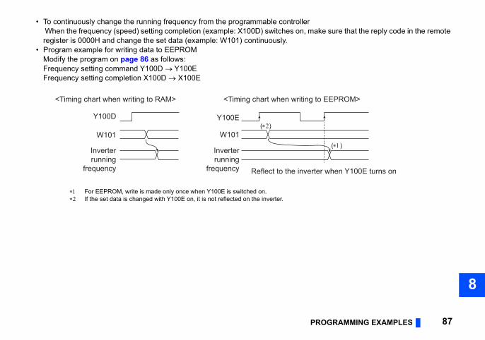
OGRAMMING EXAMPLES 87
8
• To continuously change the running frequency from the programmable controllerke sure that the reply code in the remote
(∗1)
r when Y100E turns on
EEPROM>
PR
When the frequency (speed) setting completion (example: X100D) switches on, maregister is 0000H and change the set data (example: W101) continuously.
• Program example for writing data to EEPROMModify the program on page 86 as follows:Frequency setting command Y100D Y100EFrequency setting completion X100D X100E
For EEPROM, write is made only once when Y100E is switched on. If the set data is changed with Y100E on, it is not reflected on the inverter.
<Timing chart when writing to RAM>
Y100D
W101
Inverterrunning
frequency
Y100E(∗2)
W101
Inverterrunning
frequency Reflect to the inverte
<Timing chart when writing to
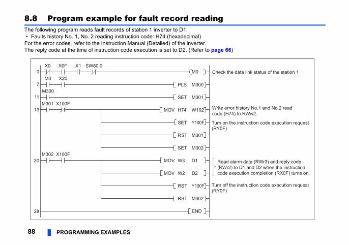
)
ror history No.1 and No.2 read74) to RWw2.
the instruction code execution request
the instruction code execution request
alarm data (RWr3) and reply code) to D1 and D2 when the instruction
execution completion (RX0F) turns on.
e data link status of the station 1
88 PROGRAMMING EXAMPLES
8.8 Program example for fault record readingThe following program reads fault records of station 1 inverter to D1. • Faults history No. 1, No. 2 reading instruction code: H74 (hexadecimal)For the error codes, refer to the Instruction Manual (Detailed) of the inverter.The reply code at the time of instruction code execution is set to D2. (Refer to page 66
SET M301
PLS M300
MOV W3 D1
MOV H74 W102 Write ercode (H
SET Y100F
Turn off (RY0F)
0
7
11
13
20
28
M0 X20
X100F
X0 X0F X1
M302 X100F
M301
M300
RST M301
SET M302
MOV W2 D2
RST Y100F
RST M302
END
Turn on (RY0F)
Read(RWr2code
Check thM0SW80.0
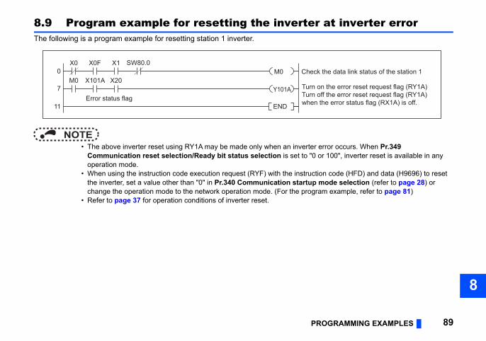
OGRAMMING EXAMPLES 89
8
at inverter error
error occurs. When Pr.349 r 100", inverter reset is available in any
on code (HFD) and data (H9696) to reset mode selection (refer to page 28) or m example, refer to page 81)
the data link status of the station 1
n the error reset request flag (RY1A)ff the error reset request flag (RY1A)the error status flag (RX1A) is off.
PR
8.9 Program example for resetting the inverterThe following is a program example for resetting station 1 inverter.
NOTE • The above inverter reset using RY1A may be made only when an inverter
Communication reset selection/Ready bit status selection is set to "0 ooperation mode.
• When using the instruction code execution request (RYF) with the instructithe inverter, set a value other than "0" in Pr.340 Communication startup change the operation mode to the network operation mode. (For the progra
• Refer to page 37 for operation conditions of inverter reset.
X0 X0F X1
M0 X101A X200
7
11 END
Check
Error status flag
Turn oTurn owhen
Y101A
M0SW80.0
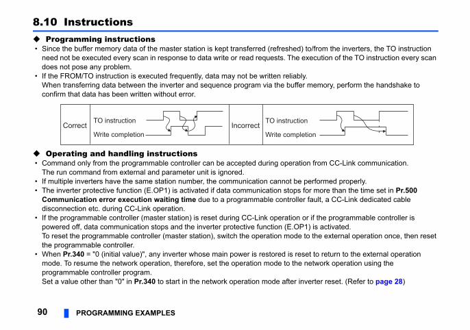
/from the inverters, the TO instruction ecution of the TO instruction every scan
emory, perform the handshake to
from CC-Link communication.
erformed properly.r more than the time set in Pr.500 ault, a CC-Link dedicated cable
if the programmable controller is ) is activated. the external operation once, then reset
t to return to the external operation etwork operation using the
erter reset. (Refer to page 28)
on
90 PROGRAMMING EXAMPLES
8.10 Instructions Programming instructions • Since the buffer memory data of the master station is kept transferred (refreshed) to
need not be executed every scan in response to data write or read requests. The exdoes not pose any problem.
• If the FROM/TO instruction is executed frequently, data may not be written reliably.When transferring data between the inverter and sequence program via the buffer mconfirm that data has been written without error.
Operating and handling instructions • Command only from the programmable controller can be accepted during operation
The run command from external and parameter unit is ignored. • If multiple inverters have the same station number, the communication cannot be p • The inverter protective function (E.OP1) is activated if data communication stops fo
Communication error execution waiting time due to a programmable controller fdisconnection etc. during CC-Link operation.
• If the programmable controller (master station) is reset during CC-Link operation orpowered off, data communication stops and the inverter protective function (E.OP1To reset the programmable controller (master station), switch the operation mode tothe programmable controller.
• When Pr.340 = "0 (initial value)", any inverter whose main power is restored is resemode. To resume the network operation, therefore, set the operation mode to the nprogrammable controller program.Set a value other than "0" in Pr.340 to start in the network operation mode after inv
TO instruction
Write completion
TO instruction
Write completiCorrect Incorrect
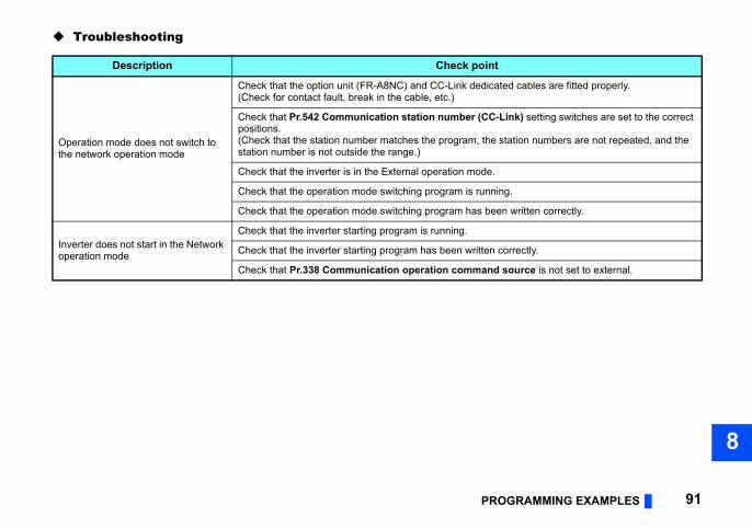
OGRAMMING EXAMPLES 91
8
t
ated cables are fitted properly.
-Link) setting switches are set to the correct
station numbers are not repeated, and the
ing.
en written correctly.
correctly.
d source is not set to external.
PR
Troubleshooting
Description Check poin
Operation mode does not switch to the network operation mode
Check that the option unit (FR-A8NC) and CC-Link dedic(Check for contact fault, break in the cable, etc.)
Check that Pr.542 Communication station number (CCpositions.(Check that the station number matches the program, thestation number is not outside the range.)
Check that the inverter is in the External operation mode.
Check that the operation mode switching program is runn
Check that the operation mode switching program has be
Inverter does not start in the Network operation mode
Check that the inverter starting program is running.
Check that the inverter starting program has been written
Check that Pr.338 Communication operation comman
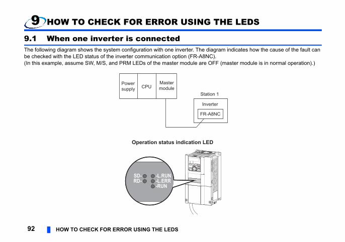
E LEDS
indicates how the cause of the fault can
aster module is in normal operation).)
92 HOW TO CHECK FOR ERROR USING THE LEDS
9 HOW TO CHECK FOR ERROR USING TH
9.1 When one inverter is connectedThe following diagram shows the system configuration with one inverter. The diagram be checked with the LED status of the inverter communication option (FR-A8NC).(In this example, assume SW, M/S, and PRM LEDs of the master module are OFF (m
Powersupply CPU
Mastermodule
Inverter
FR-A8NC
Station 1
Operation status indication LED
RD-SD-
-L.ERR-RUN
-L.RUN
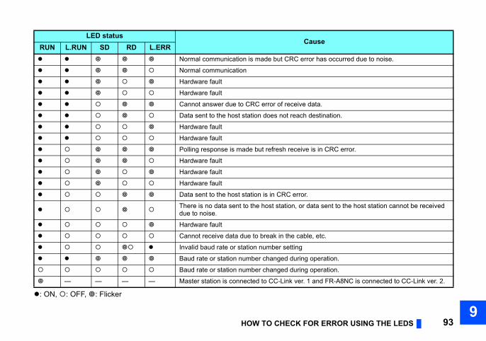
ERROR USING THE LEDS 939
e
as occurred due to noise.
.
tination.
n CRC error.
sent to the host station cannot be received
tc.
ration.
ration.
d FR-A8NC is connected to CC-Link ver. 2.
HOW TO CHECK FOR
: ON, : OFF, : Flicker
LED statusCaus
RUN L.RUN SD RD L.ERR Normal communication is made but CRC error h
Normal communication
Hardware fault
Hardware fault
Cannot answer due to CRC error of receive data
Data sent to the host station does not reach des
Hardware fault
Hardware fault
Polling response is made but refresh receive is i
Hardware fault
Hardware fault
Hardware fault
Data sent to the host station is in CRC error.
There is no data sent to the host station, or datadue to noise.
Hardware fault
Cannot receive data due to break in the cable, e
Invalid baud rate or station number setting
Baud rate or station number changed during ope
Baud rate or station number changed during ope
— — — — Master station is connected to CC-Link ver. 1 an
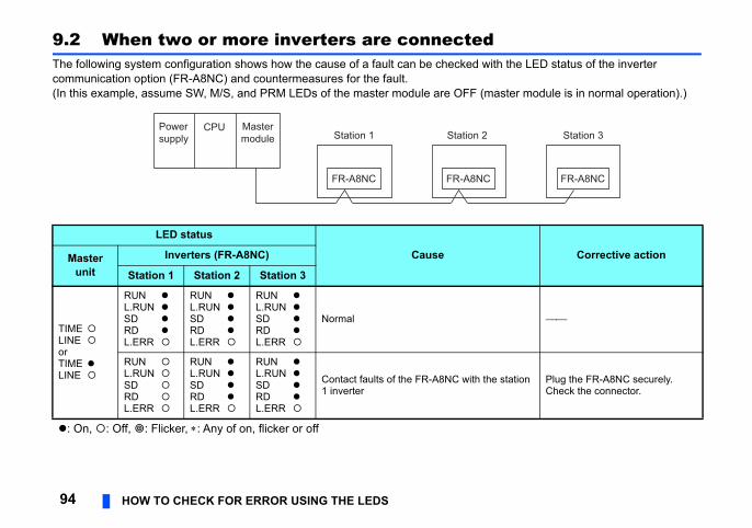
th the LED status of the inverter
aster module is in normal operation).)
Corrective action
station Plug the FR-A8NC securely.Check the connector.
Station 3
FR-A8NC
94 HOW TO CHECK FOR ERROR USING THE LEDS
9.2 When two or more inverters are connectedThe following system configuration shows how the cause of a fault can be checked wicommunication option (FR-A8NC) and countermeasures for the fault.(In this example, assume SW, M/S, and PRM LEDs of the master module are OFF (m
LED status
CauseMasterunit
Inverters (FR-A8NC)
Station 1 Station 2 Station 3
TIME LINE orTIME LINE
RUN L.RUN SD RD L.ERR
RUN L.RUN SD RD L.ERR
RUN L.RUN SD RD L.ERR
Normal
RUN L.RUN SD RD L.ERR
RUN L.RUN SD RD L.ERR
RUN L.RUN SD RD L.ERR
Contact faults of the FR-A8NC with the1 inverter
: On, : Off, : Flicker, : Any of on, flicker or off
Powersupply
CPU Mastermodule Station 1 Station 2
FR-A8NC FR-A8NC
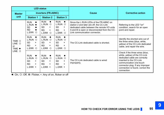
ERROR USING THE LEDS 959
C on O units the CC-
Referring to the LED "on" condition, search for an open point and repair.
d.
Identify the shorted wire out of the three wires (blue, white, yellow) of the CC-Link dedicated cable, and repair the wire.
Check if the three wires (blue, white, yellow) of the CC-Link dedicated cable are correctly inserted to the CC-Link communication one-touch connector plug. If any improper connection is found, correct the connection.
Corrective action
HOW TO CHECK FOR
: On, : Off, : Flicker, : Any of on, flicker or off
TIME LINE orTIME LINE
RUN L.RUN SD RD L.ERR
RUN L.RUN SD RD L.ERR
RUN L.RUN SD RD L.ERR
Since the L.RUN LEDs of the FR-A8Nstation 2 and later are off, the CC-Linkdedicated cable between the remote I/A and B is open or disconnected from Link communication connector.
RUN L.RUN SD RD L.ERR
RUN L.RUN SD RD L.ERR
RUN L.RUN SD RD L.ERR
The CC-Link dedicated cable is shorte
RUN L.RUN SD RD L.ERR
RUN L.RUN SD RD L.ERR
RUN L.RUN SD RD L.ERR
The CC-Link dedicated cable is wired improperly.
LED status
CauseMasterunit
Inverters (FR-A8NC)
Station 1 Station 2 Station 3
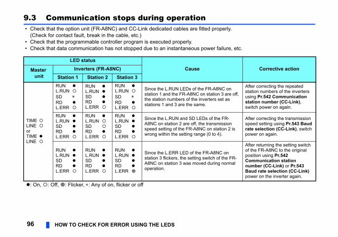
erly.
lure, etc.
Corrective action
C on are off, t as
After correcting the repeated station numbers of the inverters using Pr.542 Communication station number (CC-Link), switch power on again.
FR-sion
on 2 is
After correcting the transmission speed setting using Pr.543 Baud rate selection (CC-Link), switch power on again.
on the FR-normal
After returning the setting switch of the FR-A8NC to the original position using Pr.542 Communication station number (CC-Link) or Pr.543 Baud rate selection (CC-Link) power on the inverter again.
96 HOW TO CHECK FOR ERROR USING THE LEDS
9.3 Communication stops during operation • Check that the option unit (FR-A8NC) and CC-Link dedicated cables are fitted prop
(Check for contact fault, break in the cable, etc.) • Check that the programmable controller program is executed properly. • Check that data communication has not stopped due to an instantaneous power fai
LED statusCauseMaster
unitInverters (FR-A8NC)
Station 1 Station 2 Station 3
TIME LINE orTIME LINE
RUN L.RUN SD RD L.ERR
RUN L.RUN SD RD L.ERR
RUN L.RUN SD RD L.ERR
Since the L.RUN LEDs of the FR-A8Nstation 1 and the FR-A8NC on station 3the station numbers of the inverters sestations 1 and 3 are the same.
RUN L.RUN SD RD L.ERR
RUN L.RUN SD RD L.ERR
RUN L.RUN SD RD L.ERR
Since the L.RUN and SD LEDs of the A8NC on station 2 are off, the transmisspeed setting of the FR-A8NC on statiwrong within the setting range (0 to 4).
RUN L.RUN SD RD L.ERR
RUN L.RUN SD RD L.ERR
RUN L.RUN SD RD L.ERR
Since the L.ERR LED of the FR-A8NCstation 3 flickers, the setting switch of A8NC on station 3 was moved during operation.
: On, : Off, : Flicker, : Any of on, flicker or off
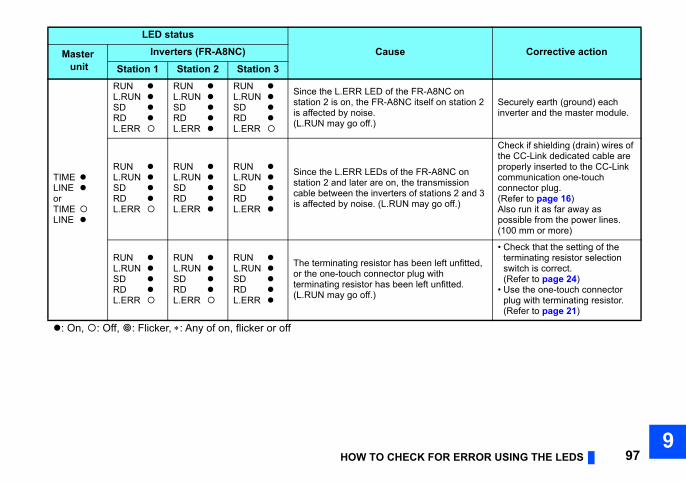
ERROR USING THE LEDS 979
on tation 2 Securely earth (ground) each
inverter and the master module.
C on sion 2 and 3 ff.)
Check if shielding (drain) wires of the CC-Link dedicated cable are properly inserted to the CC-Link communication one-touch connector plug.(Refer to page 16)Also run it as far away as possible from the power lines.(100 mm or more)
unfitted,
ed.
• Check that the setting of the terminating resistor selection switch is correct.(Refer to page 24)
• Use the one-touch connector plug with terminating resistor.(Refer to page 21)
Corrective action
HOW TO CHECK FOR
TIME LINE orTIME LINE
RUN L.RUN SD RD L.ERR
RUN L.RUN SD RD L.ERR
RUN L.RUN SD RD L.ERR
Since the L.ERR LED of the FR-A8NCstation 2 is on, the FR-A8NC itself on sis affected by noise.(L.RUN may go off.)
RUN L.RUN SD RD L.ERR
RUN L.RUN SD RD L.ERR
RUN L.RUN SD RD L.ERR
Since the L.ERR LEDs of the FR-A8Nstation 2 and later are on, the transmiscable between the inverters of stationsis affected by noise. (L.RUN may go o
RUN L.RUN SD RD L.ERR
RUN L.RUN SD RD L.ERR
RUN L.RUN SD RD L.ERR
The terminating resistor has been left or the one-touch connector plug with terminating resistor has been left unfitt(L.RUN may go off.)
LED statusCauseMaster
unitInverters (FR-A8NC)
Station 1 Station 2 Station 3
: On, : Off, : Flicker, : Any of on, flicker or off
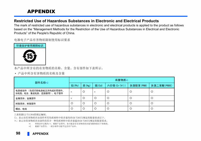
98 APPENDIX
APPENDIX
Restricted Use of Hazardous Substances in Electronic and Electrical ProductsThe mark of restricted use of hazardous substances in electronic and electrical products is applied to the product as follows based on the “Management Methods for the Restriction of the Use of Hazardous Substances in Electrical and Electronic Products” of the People's Republic of China.
电器电子产品有害物质限制使用标识要求
本产品中所含有的有害物质的名称、含量、含有部件如下表所示。
• 产品中所含有害物质的名称及含量
上表依据SJ/T11364的规定编制。
○:表示该有害物质在该部件所有均质材料中的含量均在GB/T26572规定的限量要求以下。
×:表示该有害物质在该部件的至少一种均质材料中的含量超出GB/T26572规定的限量要求。 即使表中记载为 ×,根据产品型号,也可能会有有害物质的含量为限制值以下的情况。
根据产品型号,一部分部件可能不包含在产品中。
环境保护使用期限标识
部件名称有害物质
铅(Pb) 汞(Hg) 镉(Cd) 六价铬(Cr(VI)) 多溴联苯(PBB) 多溴二苯醚(PBDE)
电路板组件(包括印刷电路板及其构成的零部件,如电阻、电容、集成电路、连接器等)、电子部件
金属壳体、金属部件
树脂壳体、树脂部件
螺丝、电线

99
MEMO
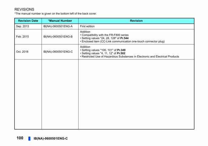
100 IB(NA)-0600501ENG-C
REVISIONS*The manual number is given on the bottom left of the back cover.
Revision Date *Manual Number Revision
Sep. 2013 IB(NA)-0600501ENG-A First edition
Feb. 2015 IB(NA)-0600501ENG-B
Addition• Compatibility with the FR-F800 series• Setting values "24, 28, 128" of Pr.544• Enclosed item (CC-Link communication one-touch connector plug)
Oct. 2018 IB(NA)-0600501ENG-C
Addition• Setting values "100, 101" of Pr.349• Setting values "4, 11, 12" of Pr.502• Restricted Use of Hazardous Substances in Electronic and Electrical Products

INV
ER
TERFR
-A8NC
INS
TRU
CTIO
N M
AN
UA
L
C
INVERTERPlug-in option
INSTRUCTION MANUAL
INVERTER
HEAD OFFICE: TOKYO BUILDING 2-7-3, MARUNOUCHI, CHIYODA-KU, TOKYO 100-8310, JAPAN
PRE-OPERATION INSTRUCTIONS 1INSTALLATION 2WIRING 3INVERTER SETTING 4FUNCTION OVERVIEW 5I/O SIGNAL LIST 6DETAILS OF INPUT AND OUTPUT SIGNALS 7PROGRAMMING EXAMPLES 8HOW TO CHECK FOR ERROR USING THE LEDS 9
FR-A8NC
communication function
IB(NA)-0600501ENG-C(1810) MEE Printed in Japan Specifications subject to change without notice.