Embed Size (px)
DESCRIPTION
Tehnical
Citation preview
Version 01/2007
SWF Krantechnik GmbH ♦ Boehringer Str.4 ♦ D-68307 Mannheim ♦ Phone +49(0)621.78990-0
Fax +49(0)621.78990-100 ♦ www.swfkrantechnik.com ♦ [email protected] SWF Krantechnik GmbH reserves the right to alter or amend the above information without notice. This document and the information contained herein, is the exclusive property of SWF Krantechnik GmbH and represents a non-public, confidential and proprietary trade secret that may not be reproduced, disclosed to third parties, altered or otherwise employed in any manner whatsoever without the express written consent of SWF Krantechnik GmbH. Copyright © SWF Krantechnik GmbH. All rights reserved.
1
01/2007 – Deutsch / English / Francais
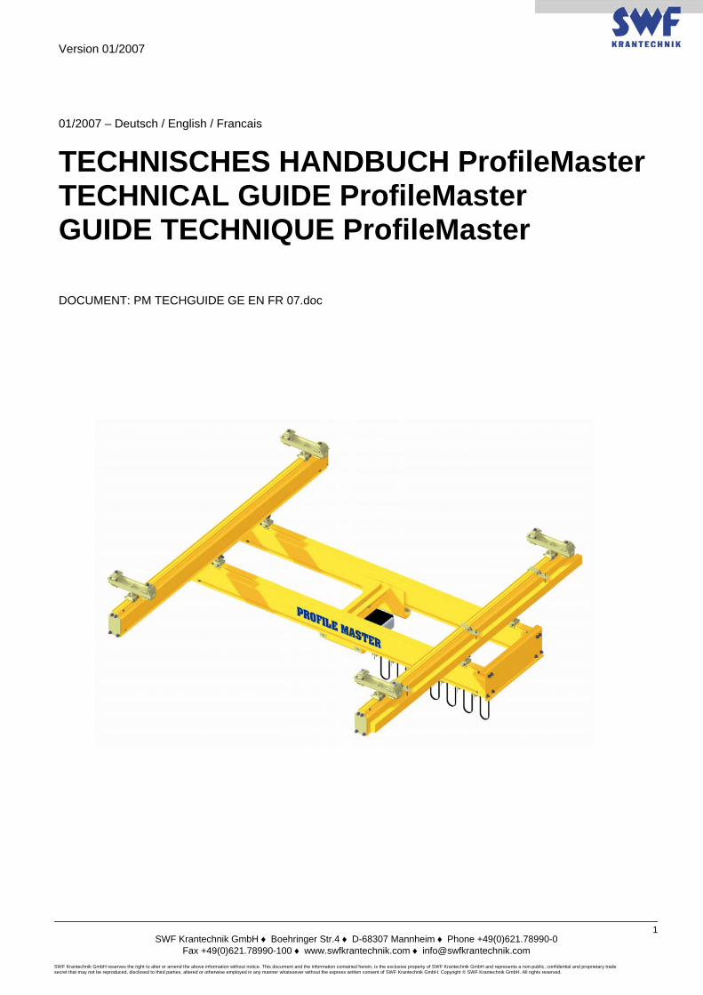
TECHNISCHES HANDBUCH ProfileMaster TECHNICAL GUIDE ProfileMaster GUIDE TECHNIQUE ProfileMaster DOCUMENT: PM TECHGUIDE GE EN FR 07.doc
Version 01/2007
SWF Krantechnik GmbH ♦ Boehringer Str.4 ♦ D-68307 Mannheim ♦ Phone +49(0)621.78990-0
Fax +49(0)621.78990-100 ♦ www.swfkrantechnik.com ♦ [email protected] SWF Krantechnik GmbH reserves the right to alter or amend the above information without notice. This document and the information contained herein, is the exclusive property of SWF Krantechnik GmbH and represents a non-public, confidential and proprietary trade secret that may not be reproduced, disclosed to third parties, altered or otherwise employed in any manner whatsoever without the express written consent of SWF Krantechnik GmbH. Copyright © SWF Krantechnik GmbH. All rights reserved.
2
PM TECHNICAL
GUIDE
GUIDE TECHNIQUE
PM
TECHNISCHES HANDBUCH
PM
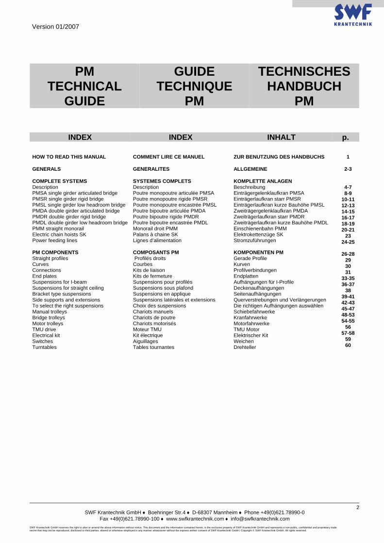
INDEX INDEX INHALT p. HOW TO READ THIS MANUAL GENERALS COMPLETE SYSTEMS Description PMSA single girder articulated bridge PMSR single girder rigid bridge PMSL single girder low headroom bridge PMDA double girder articulated bridge PMDR double girder rigid bridge PMDL double girder low headroom bridge PMM straight monorail Electric chain hoists SK Power feeding lines PM COMPONENTS Straight profiles Curves Connections End plates Suspensions for I-beam Suspensions for straight ceiling Bracket type suspensions Side supports and extensions To select the right suspensions Manual trolleys Bridge trolleys Motor trolleys TMU drive Electrical kit Switches Turntables
COMMENT LIRE CE MANUEL GENERALITES SYSTEMES COMPLETS Description Poutre monopoutre articulée PMSA Poutre monopoutre rigide PMSR Poutre monopoutre encastrée PMSL Poutre bipoutre articulée PMDA Poutre bipoutre rigide PMDR Poutre bipoutre encastrée PMDL Monorail droit PMM Palans à chaine SK Lignes d’alimentation COMPOSANTS PM Profilés droits Courbes Kits de liaison Kits de fermeture Suspensions pour profilés Suspensions sous plafond Suspensions en applique Suspensions latérales et extensions Choix des suspensions Chariots manuels Chariots de poutre Chariots motorisés Moteur TMU Kit électrique Aiguillages Tables tournantes
ZUR BENUTZUNG DES HANDBUCHS ALLGEMEINE KOMPLETTE ANLAGEN Beschreibung Einträgergelenklaufkran PMSA Einträgerlaufkran starr PMSR Einträgerlaufkran kurze Bauhöhe PMSL Zweiträgergelenklaufkran PMDA Zweiträgerlaufkran starr PMDR Zweiträgerlaufkran kurze Bauhöhe PMDL Einschienenbahn PMM Elektrokettenzüge SK Stromzuführungen KOMPONENTEN PM Gerade Profile Kurven Profilverbindungen Endplatten Aufhängungen für I-Profile Deckenaufhängungen Seitenaufhängungen Querverstrebungen und Verlängerungen Die richtigen Aufhängungen auswählen Schiebefahrwerke Kranfahrwerke Motorfahrwerke TMU Motor Elektrischer Kit Weichen Drehteller
1
2-3
4-7 8-9
10-11 12-13 14-15 16-17 18-19 20-21
23 24-25
26-28
29 30 31
33-35 36-37
38 39-41 42-43 45-47 48-53 54-55
56 57-58
59 60
Version 01/2007
SWF Krantechnik GmbH ♦ Boehringer Str.4 ♦ D-68307 Mannheim ♦ Phone +49(0)621.78990-0
Fax +49(0)621.78990-100 ♦ www.swfkrantechnik.com ♦ [email protected] SWF Krantechnik GmbH reserves the right to alter or amend the above information without notice. This document and the information contained herein, is the exclusive property of SWF Krantechnik GmbH and represents a non-public, confidential and proprietary trade secret that may not be reproduced, disclosed to third parties, altered or otherwise employed in any manner whatsoever without the express written consent of SWF Krantechnik GmbH. Copyright © SWF Krantechnik GmbH. All rights reserved.
3
HOW TO READ THIS MANUAL COMMENT LIRE CE MANUEL ZUR BENUTZUNG DES HANDBUCHS
In the first part of this Guide SWF Krantechnik presents the complete PM light crane systems, that is to say : • Bridges • Runways • Monorails and circuits and their ideal surrounding components • Chain and belt hoists • Power feeding lines Select these turn-key solutions with your own criteria : • Safe Working Load • Building dimensions • Duty factor • Working process The second part of this Guide is more technical and gives detailed information on the following sub-assemblies for complete systems : • Selection of the suspensions • Dimensions of the sub-assemblies • Code of the sub-assemblies
SWF Krantechnik vous présente dans la première partie de ce Guide les systèmes de manutention PM complets : • Ponts roulants • Chemins de roulement • Monorails et circuits et leurs indispensables compléments : • Palans à chaine et à sangle • Lignes d’ alimentation Sélectionnez ces solutions clé-en-main à partir de vos critères : • Capacité de charge • Encombrements disponibles • Cadences d’ utilisation • Process La deuxième partie de ce Guide, plus technique, est consacrée aux composants des systèmes précédents. Vous y trouverez des informations plus détaillées sur : • La sélection des suspensions • Les encombrements des sous-
ensembles • Les codes des sous-ensembles
Im ersten Teil dieses Handbuchs stellt Ihnen SWF Krantechnik die kompletten PM vor : • Krane • Fahrbahnen • Einschienenbahnen und die notwendigen Komponenten : • Elektroketten- und Bandzüge • Stromzuführungen Wählen Sie Ihre Systemlösungen nach folgenden Kriterien aus : • Traglast • Baumaße • Beanspruchungsgruppen • Anwendung Der zweite (technische) Teil dieses Handbuchs befasst sich mit den nötigen Komponenten zur Komplettierung der Leichtbaukrane. Sie finden detaillierte Informationen zu: • Auswahl der Aufhängungen • Maße der Komponenten • Kodierungen der Komponenten
Version 01/2007
SWF Krantechnik GmbH ♦ Boehringer Str.4 ♦ D-68307 Mannheim ♦ Phone +49(0)621.78990-0
Fax +49(0)621.78990-100 ♦ www.swfkrantechnik.com ♦ [email protected] SWF Krantechnik GmbH reserves the right to alter or amend the above information without notice. This document and the information contained herein, is the exclusive property of SWF Krantechnik GmbH and represents a non-public, confidential and proprietary trade secret that may not be reproduced, disclosed to third parties, altered or otherwise employed in any manner whatsoever without the express written consent of SWF Krantechnik GmbH. Copyright © SWF Krantechnik GmbH. All rights reserved.
4
GENERALS GENERALITES ALLGEMEINE
The PM construction enables to achieve light crane installations like single or double girder bridges, runways, monorails, circuits with a maximum capacity of 2000 kg. These installations, manual or motorised, can be obtained by a simple mechanical assembly on site, made with standard components of our range.
La conception PM permet la réalisation de systèmes de manutention dite « légère », à savoir poutres mono-poutre ou bi-poutre, chemins de roulement, monorails, circuits, d’une capacité maximum de 2000 kg. Ces systèmes de manutention, manuels ou motorisés, sont réalisés par simple assemblage mécanique sur le lieu de montage, à partir de composants standard de notre gamme.
Das PM ermöglicht es, eine Vielzahl von Leichtbaukrananwendungen auszuführen, wie Ein- oder Zweiträgerkrane, Einschienen- und Ovalbahnen bis zu einer Traglast von 2000 kg. Diese Anlagen, manuell oder elektrisch, können mit unseren Standardkomponenten simple und einfach Vorort montiert werden.
The use of PM will give the following benefits : • Light movements without shocks • Silent running of the trolleys • Less wear and less pollution (nylon
wheels) • Modular system • Pendulum construction (less stress on the
support structure) • Easy installation • Easy modifications if required at a later
date • 4 integrated or external power feeding
systems available • Reduced maintenance • Longer life
Choisir le système PM, c’est choisir les avantages techniques suivants : • Facilité de déplacement, sans à-coup • Silencieux • Non polluant (pas de résidus) • Système modulaire • Conception pendulaire (Efforts sur
structure réduits) • Facilité de pose • Extensions ultérieures facilement
réalisables • 4 modes d'électrification intégrée ou
externe disponibles • Entretien réduit • Longue durée de vie
Wenn Sie sich für ein PM entschieden haben, haben Sie folgende Vorteile : • Leichtes Verschieben ohne Ruck • Ruhiges Fahren • Wenig Verschleiss und Abrieb
(Nylonräder) • Modulares System • Pendelnd aufgehängte Konstruktion
(weniger Belastung der tragenden Struktur) • Leichte Installation • Nachträglich sind Änderungen leicht
möglich • 4 verschiedene externe oder interne
Stromzuführungen verfügbar • Geringer Wartungsaufwand • Hohe Lebensdauer
Frame classification according to FEM 1.001 : A4. The PM components comply with the EC directive relating to machinery 98/37/EEC. Each system is delivered with its EC declaration of conformity (Appendix IIb).
Classement Charpente selon FEM 1.001 : A4 Les composants PM sont conformes aux Directives CE relatives aux machines 98/37/CEE. Un certificat de conformité (annexe IIb) est fourni avec chaque système.
Stahlbau entsprechend Belastungsklasse A4 (FEM 1.001). Die PM Komponenten entsprechen der EG Maschinenrichtlinien 98/37/EG. Jede Anlage wird mit einer EG Konformitätserklärung (Anhang IIb) ausgeliefert.
The supporting structure (the building itself or a self-supporting structure) shall be in any case checked by a specialized organisation before the installation.
Il est dans tous les cas nécessaire de faire contrôler la structure porteuse (bâtiment ou structure indépendante) par un organisme spécialisé.
Vor der Installation muss die tragende Struktur auf jeden Fall auf Ihre Belastbarkeit von einer authorisierten Stelle geprüft werden.
Version 01/2007
SWF Krantechnik GmbH ♦ Boehringer Str.4 ♦ D-68307 Mannheim ♦ Phone +49(0)621.78990-0
Fax +49(0)621.78990-100 ♦ www.swfkrantechnik.com ♦ [email protected] SWF Krantechnik GmbH reserves the right to alter or amend the above information without notice. This document and the information contained herein, is the exclusive property of SWF Krantechnik GmbH and represents a non-public, confidential and proprietary trade secret that may not be reproduced, disclosed to third parties, altered or otherwise employed in any manner whatsoever without the express written consent of SWF Krantechnik GmbH. Copyright © SWF Krantechnik GmbH. All rights reserved.
5
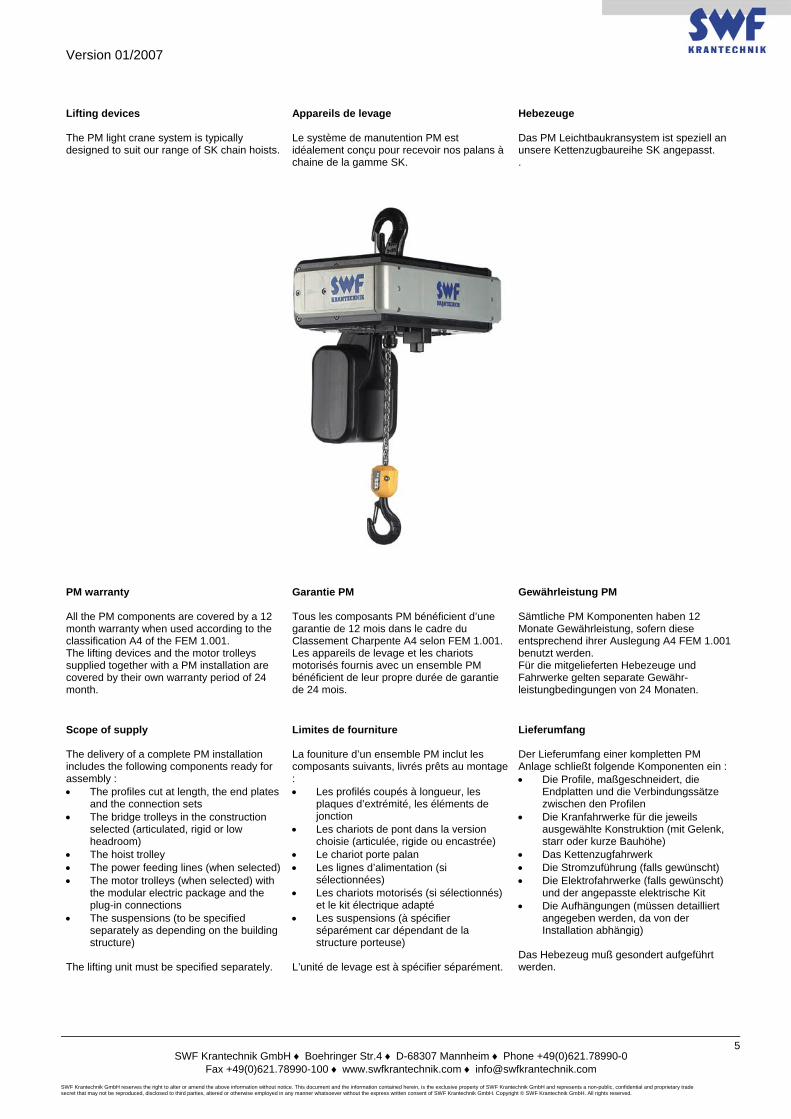
Lifting devices The PM light crane system is typically designed to suit our range of SK chain hoists.
Appareils de levage Le système de manutention PM est idéalement conçu pour recevoir nos palans à chaine de la gamme SK.
Hebezeuge Das PM Leichtbaukransystem ist speziell an unsere Kettenzugbaureihe SK angepasst. .
PM warranty All the PM components are covered by a 12 month warranty when used according to the classification A4 of the FEM 1.001. The lifting devices and the motor trolleys supplied together with a PM installation are covered by their own warranty period of 24 month.
Garantie PM Tous les composants PM bénéficient d’une garantie de 12 mois dans le cadre du Classement Charpente A4 selon FEM 1.001. Les appareils de levage et les chariots motorisés fournis avec un ensemble PM bénéficient de leur propre durée de garantie de 24 mois.
Gewährleistung PM Sämtliche PM Komponenten haben 12 Monate Gewährleistung, sofern diese entsprechend ihrer Auslegung A4 FEM 1.001 benutzt werden. Für die mitgelieferten Hebezeuge und Fahrwerke gelten separate Gewähr-leistungbedingungen von 24 Monaten.
Scope of supply The delivery of a complete PM installation includes the following components ready for assembly : • The profiles cut at length, the end plates
and the connection sets • The bridge trolleys in the construction
selected (articulated, rigid or low headroom)
• The hoist trolley • The power feeding lines (when selected) • The motor trolleys (when selected) with
the modular electric package and the plug-in connections
• The suspensions (to be specified separately as depending on the building structure)
The lifting unit must be specified separately.
Limites de fourniture La founiture d’un ensemble PM inclut les composants suivants, livrés prêts au montage : • Les profilés coupés à longueur, les
plaques d’extrémité, les éléments de jonction
• Les chariots de pont dans la version choisie (articulée, rigide ou encastrée)
• Le chariot porte palan • Les lignes d’alimentation (si
sélectionnées) • Les chariots motorisés (si sélectionnés)
et le kit électrique adapté • Les suspensions (à spécifier
séparément car dépendant de la structure porteuse)
L’unité de levage est à spécifier séparément.
Lieferumfang Der Lieferumfang einer kompletten PM Anlage schließt folgende Komponenten ein : • Die Profile, maßgeschneidert, die
Endplatten und die Verbindungssätze zwischen den Profilen
• Die Kranfahrwerke für die jeweils ausgewählte Konstruktion (mit Gelenk, starr oder kurze Bauhöhe)
• Das Kettenzugfahrwerk • Die Stromzuführung (falls gewünscht) • Die Elektrofahrwerke (falls gewünscht)
und der angepasste elektrische Kit • Die Aufhängungen (müssen detailliert
angegeben werden, da von der Installation abhängig)
Das Hebezeug muß gesondert aufgeführt werden.
Version 01/2007
SWF Krantechnik GmbH ♦ Boehringer Str.4 ♦ D-68307 Mannheim ♦ Phone +49(0)621.78990-0
Fax +49(0)621.78990-100 ♦ www.swfkrantechnik.com ♦ [email protected] SWF Krantechnik GmbH reserves the right to alter or amend the above information without notice. This document and the information contained herein, is the exclusive property of SWF Krantechnik GmbH and represents a non-public, confidential and proprietary trade secret that may not be reproduced, disclosed to third parties, altered or otherwise employed in any manner whatsoever without the express written consent of SWF Krantechnik GmbH. Copyright © SWF Krantechnik GmbH. All rights reserved.
6
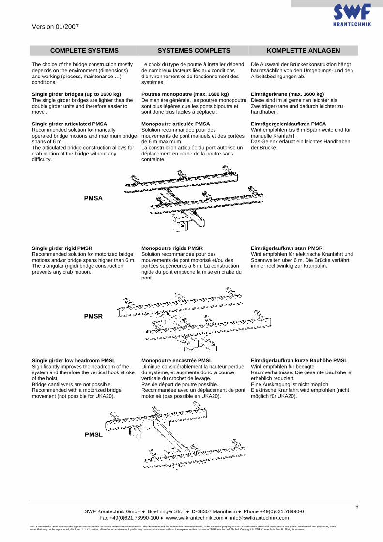
COMPLETE SYSTEMS SYSTEMES COMPLETS KOMPLETTE ANLAGEN The choice of the bridge construction mostly depends on the environment (dimensions) and working (process, maintenance …) conditions.
Le choix du type de poutre à installer dépend de nombreux facteurs liés aux conditions d’environnement et de fonctionnement des systèmes.
Die Auswahl der Brückenkonstruktion hängt hauptsächlich von den Umgebungs- und den Arbeitsbedingungen ab.
Single girder bridges (up to 1600 kg) The single girder bridges are lighter than the double girder units and therefore easier to move .
Poutres monopoutre (max. 1600 kg) De manière générale, les poutres monopoutre sont plus légères que les ponts bipoutre et sont donc plus faciles à déplacer.
Einträgerkrane (max. 1600 kg) Diese sind im allgemeinen leichter als Zweiträgerkrane und dadurch leichter zu handhaben.
Single girder articulated PMSA Recommended solution for manually operated bridge motions and maximum bridge spans of 6 m. The articulated bridge construction allows for crab motion of the bridge without any difficulty.
Monopoutre articulée PMSA Solution recommandée pour des mouvements de pont manuels et des portées de 6 m maximum. La construction articulée du pont autorise un déplacement en crabe de la poutre sans contrainte.
Einträgergelenklaufkran PMSA Wird empfohlen bis 6 m Spannweite und für manuelle Kranfahrt. Das Gelenk erlaubt ein leichtes Handhaben der Brücke.
PMSA
Single girder rigid PMSR Recommended solution for motorized bridge motions and/or bridge spans higher than 6 m. The triangular (rigid) bridge construction prevents any crab motion.
Monopoutre rigide PMSR Solution recommandée pour des mouvements de pont motorisé et/ou des portées supérieures à 6 m. La construction rigide du pont empêche la mise en crabe du pont.
Einträgerlaufkran starr PMSR Wird empfohlen für elektrische Kranfahrt und Spannweiten über 6 m. Die Brücke verfährt immer rechtwinklig zur Kranbahn.
PMSR
Single girder low headroom PMSL Significantly improves the headroom of the system and therefore the vertical hook stroke of the hoist. Bridge cantilevers are not possible. Recommended with a motorized bridge movement (not possible for UKA20).
Monopoutre encastrée PMSL Diminue considérablement la hauteur perdue du système, et augmente donc la course verticale du crochet de levage. Pas de déport de poutre possible. Recommandée avec un déplacement de pont motorisé (pas possible en UKA20).
Einträgerlaufkran kurze Bauhöhe PMSL Wird empfohlen für beengte Raumverhältnisse. Die gesamte Bauhöhe ist erheblich reduziert. Eine Auskragung ist nicht möglich. Elektrische Kranfahrt wird empfohlen (nicht möglich für UKA20).
PMSL
Version 01/2007
SWF Krantechnik GmbH ♦ Boehringer Str.4 ♦ D-68307 Mannheim ♦ Phone +49(0)621.78990-0
Fax +49(0)621.78990-100 ♦ www.swfkrantechnik.com ♦ [email protected] SWF Krantechnik GmbH reserves the right to alter or amend the above information without notice. This document and the information contained herein, is the exclusive property of SWF Krantechnik GmbH and represents a non-public, confidential and proprietary trade secret that may not be reproduced, disclosed to third parties, altered or otherwise employed in any manner whatsoever without the express written consent of SWF Krantechnik GmbH. Copyright © SWF Krantechnik GmbH. All rights reserved.
7
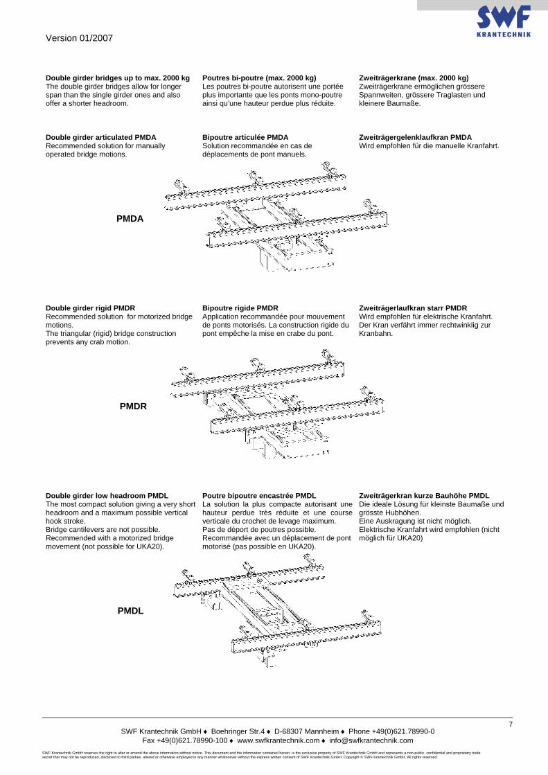
Double girder bridges up to max. 2000 kg The double girder bridges allow for longer span than the single girder ones and also offer a shorter headroom.
Poutres bi-poutre (max. 2000 kg) Les poutres bi-poutre autorisent une portée plus importante que les ponts mono-poutre ainsi qu’une hauteur perdue plus réduite.
Zweiträgerkrane (max. 2000 kg) Zweiträgerkrane ermöglichen grössere Spannweiten, grössere Traglasten und kleinere Baumaße.
Double girder articulated PMDA Recommended solution for manually operated bridge motions.
Bipoutre articulée PMDA Solution recommandée en cas de déplacements de pont manuels.
Zweiträgergelenklaufkran PMDA Wird empfohlen für die manuelle Kranfahrt.
PMDA
Double girder rigid PMDR Recommended solution for motorized bridge motions. The triangular (rigid) bridge construction prevents any crab motion.
Bipoutre rigide PMDR Application recommandée pour mouvement de ponts motorisés. La construction rigide du pont empêche la mise en crabe du pont.
Zweiträgerlaufkran starr PMDR Wird empfohlen für elektrische Kranfahrt. Der Kran verfährt immer rechtwinklig zur Kranbahn.
PMDR
Double girder low headroom PMDL The most compact solution giving a very short headroom and a maximum possible vertical hook stroke. Bridge cantilevers are not possible. Recommended with a motorized bridge movement (not possible for UKA20).
Poutre bipoutre encastrée PMDL La solution la plus compacte autorisant une hauteur perdue très réduite et une course verticale du crochet de levage maximum. Pas de déport de poutres possible. Recommandée avec un déplacement de pont motorisé (pas possible en UKA20).
Zweiträgerkran kurze Bauhöhe PMDL Die ideale Lösung für kleinste Baumaße und grösste Hubhöhen. Eine Auskragung ist nicht möglich. Elektrische Kranfahrt wird empfohlen (nicht möglich für UKA20)
PMDL

Version 01/2007
SWF Krantechnik GmbH ♦ Boehringer Str.4 ♦ D-68307 Mannheim ♦ Phone +49(0)621.78990-0
Fax +49(0)621.78990-100 ♦ www.swfkrantechnik.com ♦ [email protected] SWF Krantechnik GmbH reserves the right to alter or amend the above information without notice. This document and the information contained herein, is the exclusive property of SWF Krantechnik GmbH and represents a non-public, confidential and proprietary trade secret that may not be reproduced, disclosed to third parties, altered or otherwise employed in any manner whatsoever without the express written consent of SWF Krantechnik GmbH. Copyright © SWF Krantechnik GmbH. All rights reserved.
8
NOTES / NOTIZEN
Version 01/2007
SWF Krantechnik GmbH ♦ Boehringer Str.4 ♦ D-68307 Mannheim ♦ Phone +49(0)621.78990-0
Fax +49(0)621.78990-100 ♦ www.swfkrantechnik.com ♦ [email protected] SWF Krantechnik GmbH reserves the right to alter or amend the above information without notice. This document and the information contained herein, is the exclusive property of SWF Krantechnik GmbH and represents a non-public, confidential and proprietary trade secret that may not be reproduced, disclosed to third parties, altered or otherwise employed in any manner whatsoever without the express written consent of SWF Krantechnik GmbH. Copyright © SWF Krantechnik GmbH. All rights reserved.
9
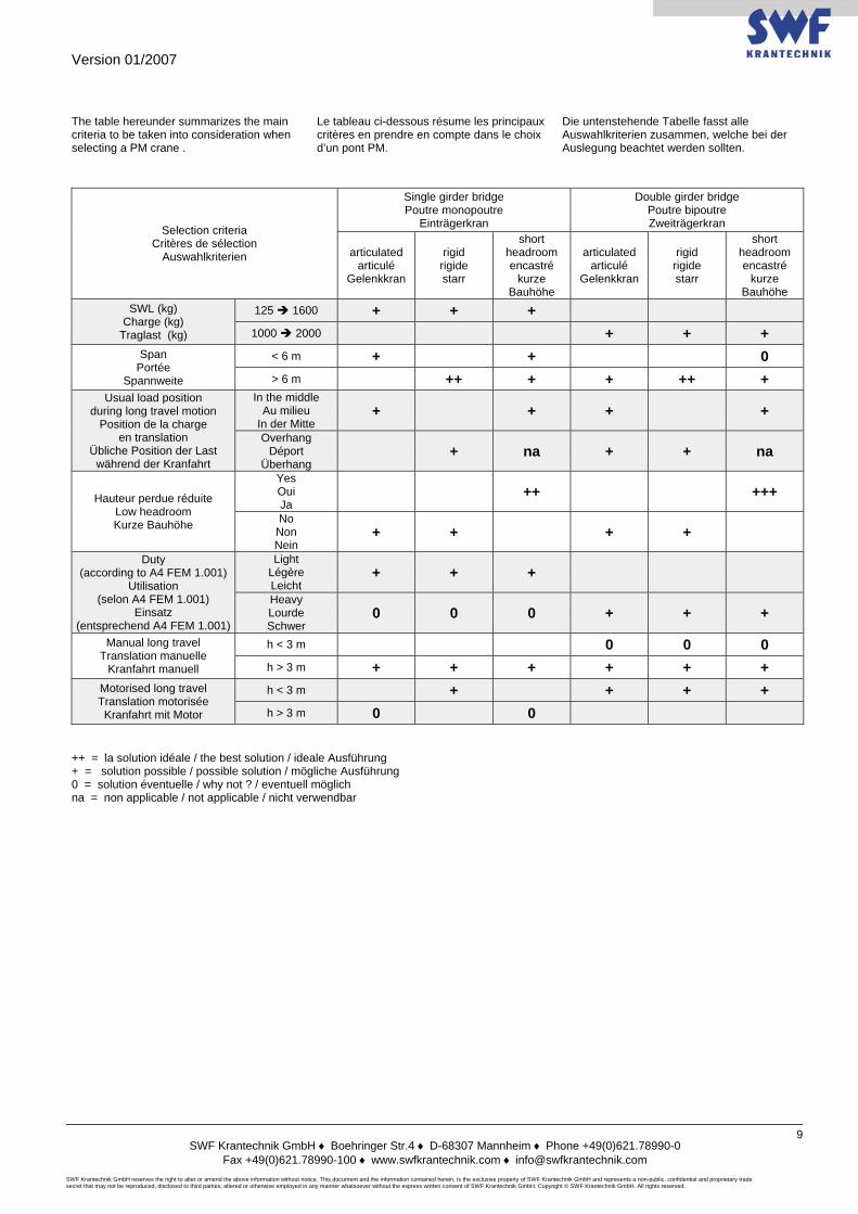
The table hereunder summarizes the main criteria to be taken into consideration when selecting a PM crane .
Le tableau ci-dessous résume les principaux critères en prendre en compte dans le choix d’un pont PM.
Die untenstehende Tabelle fasst alle Auswahlkriterien zusammen, welche bei der Auslegung beachtet werden sollten.
Selection criteria Critères de sélection
Auswahlkriterien
Single girder bridge Poutre monopoutre
Einträgerkran
Double girder bridge Poutre bipoutre Zweiträgerkran
articulated articulé
Gelenkkran
rigid rigide starr
short headroom encastré
kurze Bauhöhe
articulated articulé
Gelenkkran
rigid rigide starr
short headroom encastré
kurze Bauhöhe
SWL (kg) Charge (kg)
Traglast (kg)
125 1600 + + + 1000 2000 + + +
Span Portée
Spannweite
< 6 m + + 0 > 6 m ++ + + ++ +
Usual load position during long travel motion
Position de la charge en translation
Übliche Position der Last während der Kranfahrt
In the middle Au milieu
In der Mitte + + + +
Overhang Déport
Überhang + na + + na
Hauteur perdue réduite Low headroom Kurze Bauhöhe
Yes Oui Ja
++ +++
No Non Nein
+ + + +
Duty (according to A4 FEM 1.001)
Utilisation (selon A4 FEM 1.001)
Einsatz (entsprechend A4 FEM 1.001)
Light Légère Leicht
+ + +
Heavy Lourde Schwer
0 0 0 + + +
Manual long travel Translation manuelle
Kranfahrt manuell
h < 3 m 0 0 0 h > 3 m + + + + + +
Motorised long travel Translation motorisée Kranfahrt mit Motor
h < 3 m + + + + h > 3 m 0 0
++ = la solution idéale / the best solution / ideale Ausführung + = solution possible / possible solution / mögliche Ausführung 0 = solution éventuelle / why not ? / eventuell möglich na = non applicable / not applicable / nicht verwendbar
Version 01/2007
SWF Krantechnik GmbH ♦ Boehringer Str.4 ♦ D-68307 Mannheim ♦ Phone +49(0)621.78990-0
Fax +49(0)621.78990-100 ♦ www.swfkrantechnik.com ♦ [email protected] SWF Krantechnik GmbH reserves the right to alter or amend the above information without notice. This document and the information contained herein, is the exclusive property of SWF Krantechnik GmbH and represents a non-public, confidential and proprietary trade secret that may not be reproduced, disclosed to third parties, altered or otherwise employed in any manner whatsoever without the express written consent of SWF Krantechnik GmbH. Copyright © SWF Krantechnik GmbH. All rights reserved.
10
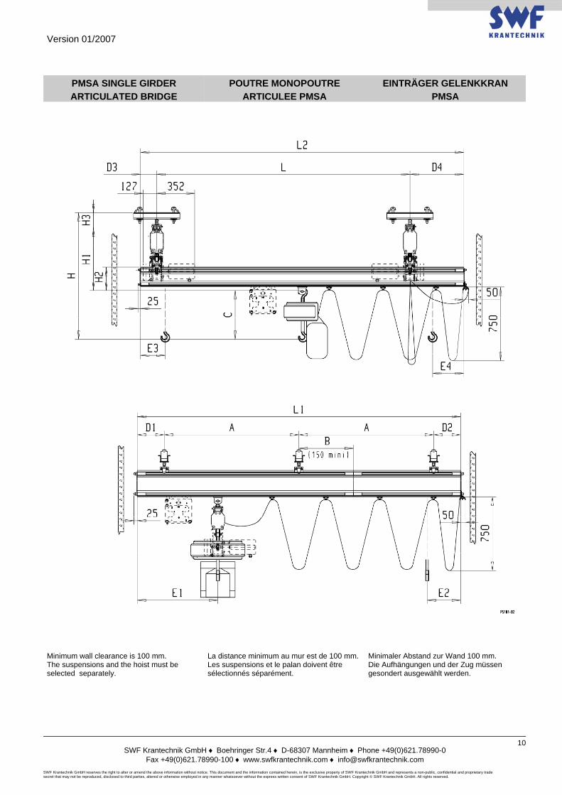
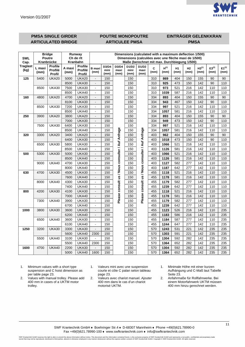
PMSA SINGLE GIRDER ARTICULATED BRIDGE
POUTRE MONOPOUTRE ARTICULEE PMSA
EINTRÄGER GELENKKRAN PMSA
Minimum wall clearance is 100 mm. The suspensions and the hoist must be selected separately.
La distance minimum au mur est de 100 mm.Les suspensions et le palan doivent être sélectionnés séparément.
Minimaler Abstand zur Wand 100 mm. Die Aufhängungen und der Zug müssen gesondert ausgewählt werden.
Version 01/2007
SWF Krantechnik GmbH ♦ Boehringer Str.4 ♦ D-68307 Mannheim ♦ Phone +49(0)621.78990-0
Fax +49(0)621.78990-100 ♦ www.swfkrantechnik.com ♦ [email protected] SWF Krantechnik GmbH reserves the right to alter or amend the above information without notice. This document and the information contained herein, is the exclusive property of SWF Krantechnik GmbH and represents a non-public, confidential and proprietary trade secret that may not be reproduced, disclosed to third parties, altered or otherwise employed in any manner whatsoever without the express written consent of SWF Krantechnik GmbH. Copyright © SWF Krantechnik GmbH. All rights reserved.
11
PMSA SINGLE GIRDER ARTICULATED BRIDGE
POUTRE MONOPOUTRE ARTICULEE PMSA
EINTRÄGER GELENKKRAN PMSA
SWL Cap.
Traglast (kg)
Bridge Poutre
Kranbrücke
Runway Ch de rlt
Kranbahn
Dimensions (calculated with a maximum deflection 1/500) Dimensions (calculées avec une flèche maxi de 1/500)
Maße (berechnet mit max. Durchbiegung 1/500)
L maxi (mm)
Profile Profilé Profil
A maxi(mm)
Profile Profilé Profil
B maxi (mm)
D3/D4 mini (mm)
D3/D4 maxi (mm)
D1/D2 mini (mm)
D1/D2 maxi (mm)
C (mm)
H(1) (mm)
H1 (mm)
H2 (mm)
H3(1) (mm)
E3(2) (mm)
E1(2) (mm)
125 5400 UKA20 5000 UKA20 - 150
Plea
se c
onsu
lt us
/ N
ous
cons
ulte
r / A
uf A
nfra
ge
150
Plea
se c
onsu
lt us
/ N
ous
cons
ulte
r / A
uf A
nfra
ge
310 869 404 150 155 90 90 8500 UKA30 - 150 150 310 925 473 150 142 90 110 8500 UKA30 7500 UKA30 - 150 150 310 973 521 216 142 110 110 8500 UKA40 - 150 150 310 1039 587 216 142 110 110
160 4800 UKA20 4700 UKA20 - 150 150 334 893 404 150 155 90 90 8100 UKA30 - 150 150 334 943 467 150 142 90 110 8500 UKA30 7200 UKA30 - 150 150 334 997 521 216 142 110 110 8500 UKA40 - 150 150 334 1057 581 216 142 110 110
250 3900 UKA20 3800 UKA20 - 150 150 334 893 404 150 155 90 90 7000 UKA30 - 150 150 334 949 473 150 142 90 110 7500 UKA30 6400 UKA30 - 150 150 334 997 521 216 142 110 110 8500 UKA40 - 150 150 334 1057 581 216 142 110 110
320 3300 UKA20 3400 UKA20 - 150 150 403 962 404 150 155 90 90 6400 UKA30 - 150 150 403 1018 473 150 142 90 110 6500 UKA30 5800 UKA30 - 150 150 403 1066 521 216 142 110 110 8500 UKA40 - 150 150 403 1126 581 216 142 110 110
500 5300 UKA30 5000 UKA30 - 150 150 403 1066 521 216 142 110 110 8500 UKA40 - 150 150 403 1126 581 216 142 110 110 9000 UKA40 4700 UKA30 - 150 150 403 1127 582 277 142 110 110 8000 UKA40 - 150 150 403 1187 642 277 142 110 110
630 4700 UKA30 4500 UKA30 - 150 150 455 1118 521 216 142 110 110 7600 UKA40 - 150 150 455 1178 581 216 142 110 110 8000 UKA40 4300 UKA30 - 150 150 455 1179 582 277 142 110 110 7400 UKA40 - 150 150 455 1239 642 277 142 110 110
800 4200 UKA30 4100 UKA30 - 150 150 455 1118 521 216 142 110 110 7000 UKA40 - 150 150 455 1178 581 216 142 110 110 7300 UKA40 3900 UKA30 - 150 150 455 1179 582 277 142 110 110 6700 UKA40 - 150 150 455 1239 642 277 142 110 110
1000 3800 UKA30 3600 UKA30 - 150 150 455 1123 526 216 142 110 235 6200 UKA40 - 150 150 455 1183 586 216 142 110 235 6500 UKA40 3600 UKA30 - 150 150 455 1184 587 277 142 110 235 6100 UKA40 - 150 150 455 1244 647 277 142 110 235
1250 3200 UKA30 3300 UKA30 - 150 150 570 1243 531 221 142 235 235 5600 UKA40 2300 150 150 570 1303 591 221 142 235 235 5500 UKA40 3100 UKA30 - 150 150 570 1304 592 282 142 235 235 5500 UKA40 2300 150 150 570 1364 652 282 142 235 235
1600 4700 UKA40 2200 UKA30 - 150 150 570 1304 592 282 142 235 235 5000 UKA40 1600 150 150 570 1364 652 282 142 235 235
1. Minimum values with a short type
suspension and C hoist dimension as per table page 23.
2. Values with manual trolley. Please add 400 mm in cases of a UKTM motor trolley.
1. Valeurs mini avec une suspension courte et côte C palan selon tableau page 23.
2. Valeurs avec chariot manuel. Ajouter 400 mm dans le cas d’un chariot motorisé UKTM.
1. Minimale Höhe mit einer kurzen Aufhängung und C-Maß laut Tabelle Seite 23.
2. Anfahrmaße für Rollfahrwerke. Bei einem Motorfahrwerk UKTM müssen 400 mm hinzu gerechnet werden.
Version 01/2007
SWF Krantechnik GmbH ♦ Boehringer Str.4 ♦ D-68307 Mannheim ♦ Phone +49(0)621.78990-0
Fax +49(0)621.78990-100 ♦ www.swfkrantechnik.com ♦ [email protected] SWF Krantechnik GmbH reserves the right to alter or amend the above information without notice. This document and the information contained herein, is the exclusive property of SWF Krantechnik GmbH and represents a non-public, confidential and proprietary trade secret that may not be reproduced, disclosed to third parties, altered or otherwise employed in any manner whatsoever without the express written consent of SWF Krantechnik GmbH. Copyright © SWF Krantechnik GmbH. All rights reserved.
12
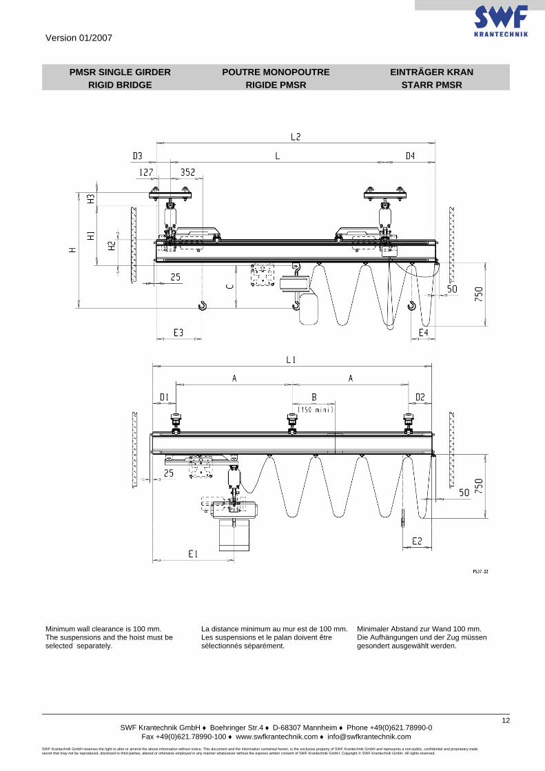
PMSR SINGLE GIRDER RIGID BRIDGE
POUTRE MONOPOUTRE RIGIDE PMSR
EINTRÄGER KRAN STARR PMSR
Minimum wall clearance is 100 mm. The suspensions and the hoist must be selected separately.
La distance minimum au mur est de 100 mm.Les suspensions et le palan doivent être sélectionnés séparément.
Minimaler Abstand zur Wand 100 mm. Die Aufhängungen und der Zug müssen gesondert ausgewählt werden.
Version 01/2007
SWF Krantechnik GmbH ♦ Boehringer Str.4 ♦ D-68307 Mannheim ♦ Phone +49(0)621.78990-0
Fax +49(0)621.78990-100 ♦ www.swfkrantechnik.com ♦ [email protected] SWF Krantechnik GmbH reserves the right to alter or amend the above information without notice. This document and the information contained herein, is the exclusive property of SWF Krantechnik GmbH and represents a non-public, confidential and proprietary trade secret that may not be reproduced, disclosed to third parties, altered or otherwise employed in any manner whatsoever without the express written consent of SWF Krantechnik GmbH. Copyright © SWF Krantechnik GmbH. All rights reserved.
13
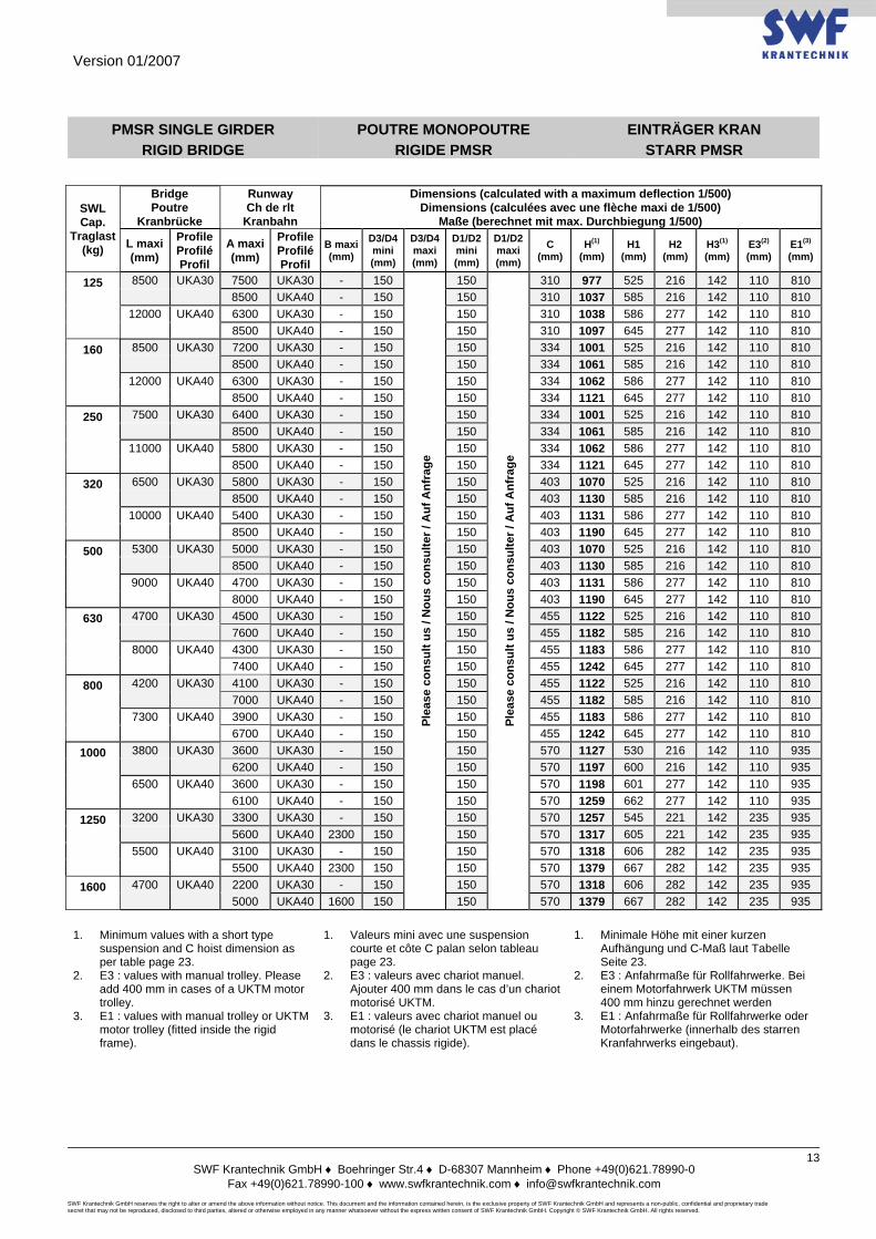
PMSR SINGLE GIRDER RIGID BRIDGE
POUTRE MONOPOUTRE RIGIDE PMSR
EINTRÄGER KRAN STARR PMSR
SWL Cap.
Traglast (kg)
Bridge Poutre
Kranbrücke
Runway Ch de rlt
Kranbahn
Dimensions (calculated with a maximum deflection 1/500) Dimensions (calculées avec une flèche maxi de 1/500)
Maße (berechnet mit max. Durchbiegung 1/500)
L maxi (mm)
Profile Profilé Profil
A maxi(mm)
Profile Profilé Profil
B maxi (mm)
D3/D4 mini (mm)
D3/D4 maxi (mm)
D1/D2 mini (mm)
D1/D2 maxi (mm)
C (mm)
H(1) (mm)
H1 (mm)
H2 (mm)
H3(1) (mm)
E3(2) (mm)
E1(3) (mm)
125 8500 UKA30 7500 UKA30 - 150
Plea
se c
onsu
lt us
/ N
ous
cons
ulte
r / A
uf A
nfra
ge
150
Plea
se c
onsu
lt us
/ N
ous
cons
ulte
r / A
uf A
nfra
ge
310 977 525 216 142 110 810 8500 UKA40 - 150 150 310 1037 585 216 142 110 810 12000 UKA40 6300 UKA30 - 150 150 310 1038 586 277 142 110 810 8500 UKA40 - 150 150 310 1097 645 277 142 110 810
160 8500 UKA30 7200 UKA30 - 150 150 334 1001 525 216 142 110 810 8500 UKA40 - 150 150 334 1061 585 216 142 110 810 12000 UKA40 6300 UKA30 - 150 150 334 1062 586 277 142 110 810 8500 UKA40 - 150 150 334 1121 645 277 142 110 810
250 7500 UKA30 6400 UKA30 - 150 150 334 1001 525 216 142 110 810 8500 UKA40 - 150 150 334 1061 585 216 142 110 810 11000 UKA40 5800 UKA30 - 150 150 334 1062 586 277 142 110 810 8500 UKA40 - 150 150 334 1121 645 277 142 110 810
320 6500 UKA30 5800 UKA30 - 150 150 403 1070 525 216 142 110 810 8500 UKA40 - 150 150 403 1130 585 216 142 110 810 10000 UKA40 5400 UKA30 - 150 150 403 1131 586 277 142 110 810 8500 UKA40 - 150 150 403 1190 645 277 142 110 810
500 5300 UKA30 5000 UKA30 - 150 150 403 1070 525 216 142 110 810 8500 UKA40 - 150 150 403 1130 585 216 142 110 810 9000 UKA40 4700 UKA30 - 150 150 403 1131 586 277 142 110 810 8000 UKA40 - 150 150 403 1190 645 277 142 110 810
630 4700 UKA30 4500 UKA30 - 150 150 455 1122 525 216 142 110 810 7600 UKA40 - 150 150 455 1182 585 216 142 110 810 8000 UKA40 4300 UKA30 - 150 150 455 1183 586 277 142 110 810 7400 UKA40 - 150 150 455 1242 645 277 142 110 810
800 4200 UKA30 4100 UKA30 - 150 150 455 1122 525 216 142 110 810 7000 UKA40 - 150 150 455 1182 585 216 142 110 810 7300 UKA40 3900 UKA30 - 150 150 455 1183 586 277 142 110 810 6700 UKA40 - 150 150 455 1242 645 277 142 110 810
1000 3800 UKA30 3600 UKA30 - 150 150 570 1127 530 216 142 110 935 6200 UKA40 - 150 150 570 1197 600 216 142 110 935 6500 UKA40 3600 UKA30 - 150 150 570 1198 601 277 142 110 935 6100 UKA40 - 150 150 570 1259 662 277 142 110 935
1250 3200 UKA30 3300 UKA30 - 150 150 570 1257 545 221 142 235 935 5600 UKA40 2300 150 150 570 1317 605 221 142 235 935 5500 UKA40 3100 UKA30 - 150 150 570 1318 606 282 142 235 935 5500 UKA40 2300 150 150 570 1379 667 282 142 235 935
1600 4700 UKA40 2200 UKA30 - 150 150 570 1318 606 282 142 235 935 5000 UKA40 1600 150 150 570 1379 667 282 142 235 935
1. Minimum values with a short type
suspension and C hoist dimension as per table page 23.
2. E3 : values with manual trolley. Please add 400 mm in cases of a UKTM motor trolley.
3. E1 : values with manual trolley or UKTM motor trolley (fitted inside the rigid frame).
1. Valeurs mini avec une suspension courte et côte C palan selon tableau page 23.
2. E3 : valeurs avec chariot manuel. Ajouter 400 mm dans le cas d’un chariot motorisé UKTM.
3. E1 : valeurs avec chariot manuel ou motorisé (le chariot UKTM est placé dans le chassis rigide).
1. Minimale Höhe mit einer kurzen Aufhängung und C-Maß laut Tabelle Seite 23.
2. E3 : Anfahrmaße für Rollfahrwerke. Bei einem Motorfahrwerk UKTM müssen 400 mm hinzu gerechnet werden
3. E1 : Anfahrmaße für Rollfahrwerke oder Motorfahrwerke (innerhalb des starren Kranfahrwerks eingebaut).
Version 01/2007
SWF Krantechnik GmbH ♦ Boehringer Str.4 ♦ D-68307 Mannheim ♦ Phone +49(0)621.78990-0
Fax +49(0)621.78990-100 ♦ www.swfkrantechnik.com ♦ [email protected] SWF Krantechnik GmbH reserves the right to alter or amend the above information without notice. This document and the information contained herein, is the exclusive property of SWF Krantechnik GmbH and represents a non-public, confidential and proprietary trade secret that may not be reproduced, disclosed to third parties, altered or otherwise employed in any manner whatsoever without the express written consent of SWF Krantechnik GmbH. Copyright © SWF Krantechnik GmbH. All rights reserved.
14
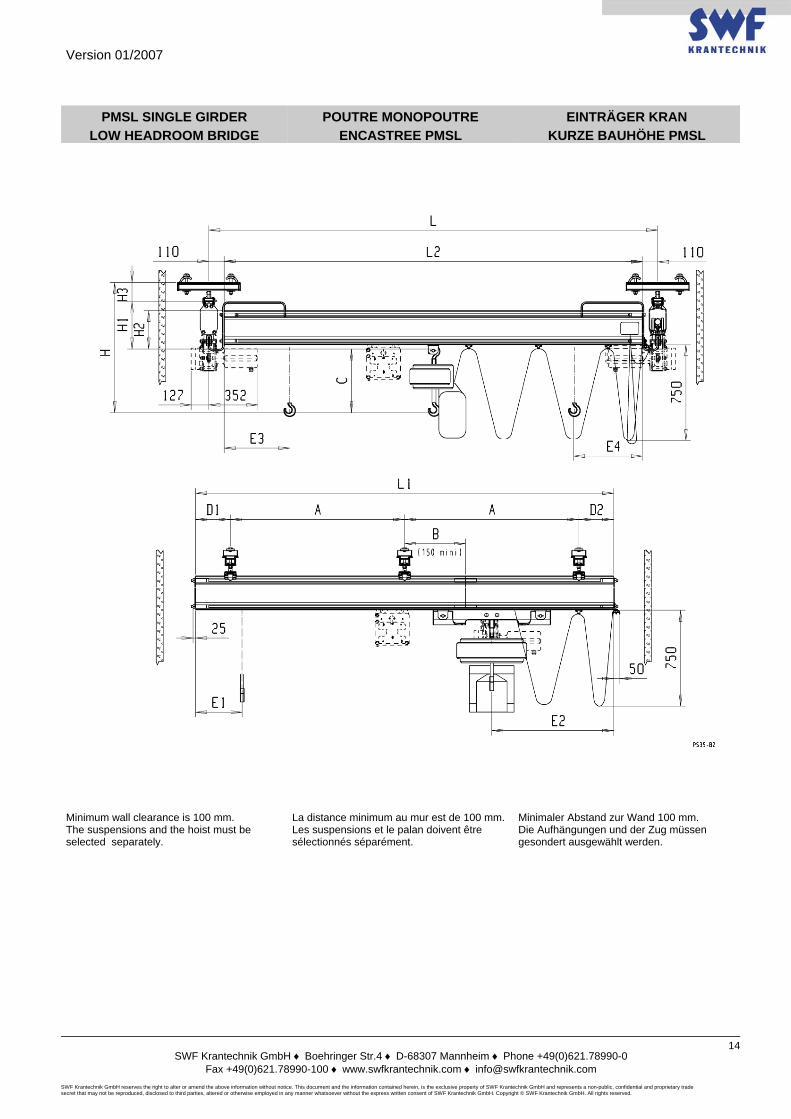
PMSL SINGLE GIRDER LOW HEADROOM BRIDGE
POUTRE MONOPOUTRE ENCASTREE PMSL
EINTRÄGER KRAN KURZE BAUHÖHE PMSL
Minimum wall clearance is 100 mm. The suspensions and the hoist must be selected separately.
La distance minimum au mur est de 100 mm.Les suspensions et le palan doivent être sélectionnés séparément.
Minimaler Abstand zur Wand 100 mm. Die Aufhängungen und der Zug müssen gesondert ausgewählt werden.
Version 01/2007
SWF Krantechnik GmbH ♦ Boehringer Str.4 ♦ D-68307 Mannheim ♦ Phone +49(0)621.78990-0
Fax +49(0)621.78990-100 ♦ www.swfkrantechnik.com ♦ [email protected] SWF Krantechnik GmbH reserves the right to alter or amend the above information without notice. This document and the information contained herein, is the exclusive property of SWF Krantechnik GmbH and represents a non-public, confidential and proprietary trade secret that may not be reproduced, disclosed to third parties, altered or otherwise employed in any manner whatsoever without the express written consent of SWF Krantechnik GmbH. Copyright © SWF Krantechnik GmbH. All rights reserved.
15
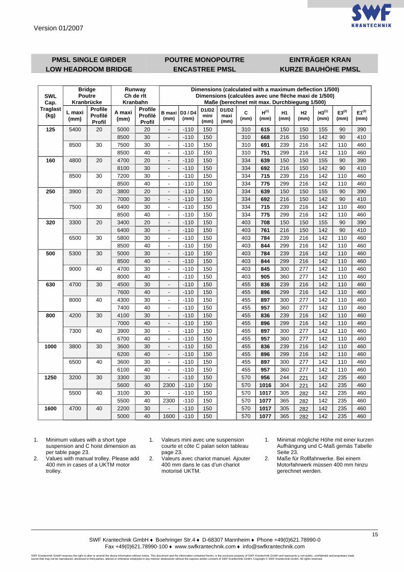
PMSL SINGLE GIRDER LOW HEADROOM BRIDGE
POUTRE MONOPOUTRE ENCASTREE PMSL
EINTRÄGER KRAN KURZE BAUHÖHE PMSL
SWL Cap.
Traglast (kg)
Bridge Poutre
Kranbrücke
Runway Ch de rlt
Kranbahn
Dimensions (calculated with a maximum deflection 1/500) Dimensions (calculées avec une flèche maxi de 1/500)
Maße (berechnet mit max. Durchbiegung 1/500)
L maxi (mm)
Profile Profilé Profil
A maxi (mm)
Profile Profilé Profil
B maxi(mm)
D3 / D4 (mm)
D1/D2 mini (mm)
D1/D2 maxi (mm)
C (mm)
H(1) (mm)
H1 (mm)
H2 (mm)
H3(1) (mm)
E3(2) (mm)
E1(2) (mm)
125 5400 20 5000 20 - -110 150
310 615 150 150 155 90 390 8500 30 - -110 150 310 668 216 150 142 90 410 8500 30 7500 30 - -110 150 310 691 239 216 142 110 460 8500 40 - -110 150 310 751 299 216 142 110 460
160 4800 20 4700 20 - -110 150 334 639 150 150 155 90 390 8100 30 - -110 150 334 692 216 150 142 90 410 8500 30 7200 30 - -110 150 334 715 239 216 142 110 460 8500 40 - -110 150 334 775 299 216 142 110 460
250 3900 20 3800 20 - -110 150 334 639 150 150 155 90 390 7000 30 - -110 150 334 692 216 150 142 90 410 7500 30 6400 30 - -110 150 334 715 239 216 142 110 460 8500 40 - -110 150 334 775 299 216 142 110 460
320 3300 20 3400 20 - -110 150 403 708 150 150 155 90 390 6400 30 - -110 150 403 761 216 150 142 90 410 6500 30 5800 30 - -110 150 403 784 239 216 142 110 460 8500 40 - -110 150 403 844 299 216 142 110 460
500 5300 30 5000 30 - -110 150 403 784 239 216 142 110 460 8500 40 - -110 150 403 844 299 216 142 110 460 9000 40 4700 30 - -110 150 403 845 300 277 142 110 460 8000 40 - -110 150 403 905 360 277 142 110 460
630 4700 30 4500 30 - -110 150 455 836 239 216 142 110 460 7600 40 - -110 150 455 896 299 216 142 110 460 8000 40 4300 30 - -110 150 455 897 300 277 142 110 460 7400 40 - -110 150 455 957 360 277 142 110 460
800 4200 30 4100 30 - -110 150 455 836 239 216 142 110 460 7000 40 - -110 150 455 896 299 216 142 110 460 7300 40 3900 30 - -110 150 455 897 300 277 142 110 460 6700 40 - -110 150 455 957 360 277 142 110 460
1000 3800 30 3600 30 - -110 150 455 836 239 216 142 110 460 6200 40 - -110 150 455 896 299 216 142 110 460 6500 40 3600 30 - -110 150 455 897 300 277 142 110 460 6100 40 - -110 150 455 957 360 277 142 110 460
1250 3200 30 3300 30 - -110 150 570 956 244 221 142 235 460 5600 40 2300 -110 150 570 1016 304 221 142 235 460 5500 40 3100 30 - -110 150 570 1017 305 282 142 235 460 5500 40 2300 -110 150 570 1077 365 282 142 235 460
1600 4700 40 2200 30 - -110 150 570 1017 305 282 142 235 460 5000 40 1600 -110 150 570 1077 365 282 142 235 460
1. Minimum values with a short type
suspension and C hoist dimension as per table page 23.
2. Values with manual trolley. Please add 400 mm in cases of a UKTM motor trolley.
1. Valeurs mini avec une suspension courte et côte C palan selon tableau page 23.
2. Valeurs avec chariot manuel. Ajouter 400 mm dans le cas d’un chariot motorisé UKTM.
1. Minimal mögliche Höhe mit einer kurzen Aufhängung und C-Maß gemäs Tabelle Seite 23.
2. Maße für Rollfahrwerke. Bei einem Motorfahrwerk müssen 400 mm hinzu gerechnet werden.
Version 01/2007
SWF Krantechnik GmbH ♦ Boehringer Str.4 ♦ D-68307 Mannheim ♦ Phone +49(0)621.78990-0
Fax +49(0)621.78990-100 ♦ www.swfkrantechnik.com ♦ [email protected] SWF Krantechnik GmbH reserves the right to alter or amend the above information without notice. This document and the information contained herein, is the exclusive property of SWF Krantechnik GmbH and represents a non-public, confidential and proprietary trade secret that may not be reproduced, disclosed to third parties, altered or otherwise employed in any manner whatsoever without the express written consent of SWF Krantechnik GmbH. Copyright © SWF Krantechnik GmbH. All rights reserved.
16
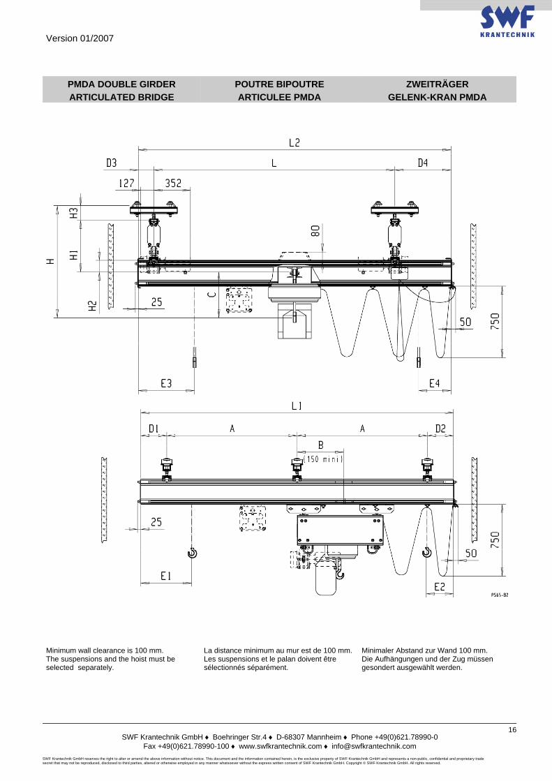
PMDA DOUBLE GIRDER ARTICULATED BRIDGE
POUTRE BIPOUTRE ARTICULEE PMDA
ZWEITRÄGER GELENK-KRAN PMDA
Minimum wall clearance is 100 mm. The suspensions and the hoist must be selected separately.
La distance minimum au mur est de 100 mm.Les suspensions et le palan doivent être sélectionnés séparément.
Minimaler Abstand zur Wand 100 mm. Die Aufhängungen und der Zug müssen gesondert ausgewählt werden.

Version 01/2007
SWF Krantechnik GmbH ♦ Boehringer Str.4 ♦ D-68307 Mannheim ♦ Phone +49(0)621.78990-0
Fax +49(0)621.78990-100 ♦ www.swfkrantechnik.com ♦ [email protected] SWF Krantechnik GmbH reserves the right to alter or amend the above information without notice. This document and the information contained herein, is the exclusive property of SWF Krantechnik GmbH and represents a non-public, confidential and proprietary trade secret that may not be reproduced, disclosed to third parties, altered or otherwise employed in any manner whatsoever without the express written consent of SWF Krantechnik GmbH. Copyright © SWF Krantechnik GmbH. All rights reserved.
17
PMDA DOUBLE GIRDER ARTICULATED BRIDGE
POUTRE BIPOUTRE ARTICULEE PMDA
ZWEITRÄGER GELENK-KRAN PMDA
SWL Cap.
Traglast (kg)
Bridge Poutre
Kranbrücke
Runway Ch de rlt
Kranbahn
Dimensions (calculated with a maximum deflection 1/500) Dimensions (calculées avec une flèche maxi de 1/500)
Maße (berechnet mit max. Durchbiegung 1/500)
L maxi (mm)
Profile Profilé Profil
A maxi(mm)
Profile Profilé Profil
B maxi (mm)
D3/D4 mini (mm)
D3/D4 maxi (mm)
D1/D2 mini (mm)
D1/D2 maxi (mm)
C (mm)
H(1) (mm)
H1 (mm)
H2 (mm)
H3(1) (mm)
E3(2) (mm)
E1(2) (mm)
125 7000 UKA20 4200 UKA20 - 150
Plea
se c
onsu
lt us
/ N
ous
cons
ulte
r / A
uf A
nfra
ge
150
Plea
se c
onsu
lt us
/ N
ous
cons
ulte
r / A
uf A
nfra
ge
334 681 192 -57 155 250 390 8500 UKA30 - 150 150 334 736 260 -57 142 250 410 8500 UKA30 6300 UKA30 - 150 150 334 832 356 51 142 285 460 9500 UKA40 - 150 150 334 892 416 51 142 285 460
160 6500 UKA20 4200 UKA20 - 150 150 334 681 192 -57 155 250 390 7700 UKA30 - 150 150 334 736 260 -57 142 250 410 8500 UKA30 6000 UKA30 - 150 150 334 832 356 51 142 285 460 9500 UKA40 - 150 150 334 892 416 51 142 285 460
250 5400 UKA20 3700 UKA20 - 150 150 334 681 192 -57 155 250 390 6700 UKA30 - 150 150 334 736 260 -57 142 250 410 8500 UKA30 5400 UKA30 - 150 150 334 832 356 51 142 285 460 9300 UKA40 - 150 150 334 892 416 51 142 285 460
320 4800 UKA20 3300 UKA20 - 150 150 403 750 192 -57 155 250 390 6000 UKA30 - 150 150 403 805 260 -57 142 250 410 8500 UKA30 5100 UKA30 - 150 150 403 901 356 51 142 285 460 8600 UKA40 - 150 150 403 961 416 51 142 285 460
500 3900 UKA20 5100 UKA30 - 150 150 403 805 260 -57 142 285 460 7200 UKA30 4500 UKA30 - 150 150 403 901 356 51 142 285 460 7600 UKA40 - 150 150 403 961 416 51 142 285 460 10500 UKA40 4100 UKA30 - 150 150 403 962 417 112 142 285 460 6900 UKA40 - 150 150 403 1022 477 112 142 285 460
630 6500 UKA30 4200 UKA30 - 150 150 455 953 356 51 142 285 460 7100 UKA40 - 150 150 455 1013 416 51 142 285 460 10500 UKA40 3800 UKA30 - 150 150 455 1014 417 112 142 285 460 6500 UKA40 - 150 150 455 1074 477 112 142 285 460
800 5900 UKA30 3900 UKA30 - 150 150 455 953 356 51 142 285 460 6600 UKA40 - 150 150 455 1013 416 51 142 285 460 10000 UKA40 3600 UKA30 - 150 150 455 1014 417 112 142 285 460 6100 UKA40 - 150 150 455 1074 477 112 142 285 460
1000 5300 UKA30 3600 UKA30 - 150 150 455 953 356 51 142 285 460 6000 UKA40 - 150 150 455 1013 416 51 142 285 460 9000 UKA40 3400 UKA30 - 150 150 455 1014 417 112 142 285 460 5700 UKA40 - 150 150 455 1074 477 112 142 285 460
1250 4700 UKA30 3200 UKA30 - 150 150 570 1068 356 51 142 285 460 5500 UKA40 2300 150 150 570 1128 416 51 142 285 460 8000 UKA40 3100 UKA30 - 150 150 570 1129 417 112 142 285 460 5500 UKA40 2300 150 150 570 1189 477 112 142 285 460
1600 4200 UKA30 2900 UKA30 150 150 570 1068 356 51 142 285 460 4900 UKA40 1600 150 150 570 1128 416 51 142 285 460 7200 UKA40 2800 UKA30 150 150 570 1129 417 112 142 285 460 4800 UKA40 1600 150 150 570 1189 477 112 142 285 460
2000 3900 UKA30 2700 UKA30 150 150 570 1073 361 51 142 285 585 4500 UKA40 1200 150 150 570 1133 421 51 142 285 585 6500 UKA40 2700 UKA30 150 150 570 1134 422 112 142 285 585 4400 UKA40 1200 150 150 570 1194 482 112 142 285 585
1. Minimum values with a short type suspension and C hoist dimension as per table page 23.
2. Values with manual trolley. Please add 400 mm in cases of a UKTM motor trolley.
1. Valeurs mini avec une suspension courte et côte C palan selon tableau page 23.
2. Valeurs avec chariot manuel. Ajouter 400 mm dans le cas d’un chariot motorisé UKTM.
1. Minimal mögliche Höhe mit einer kurzen Aufhängung und C-Maß gemäs Tabelle Seite 23.
2. Maße für Rollfahrwerke. Bei einem Motorfahrwerk müssen 400 mm hinzu gerechnet werden.
Version 01/2007
SWF Krantechnik GmbH ♦ Boehringer Str.4 ♦ D-68307 Mannheim ♦ Phone +49(0)621.78990-0
Fax +49(0)621.78990-100 ♦ www.swfkrantechnik.com ♦ [email protected] SWF Krantechnik GmbH reserves the right to alter or amend the above information without notice. This document and the information contained herein, is the exclusive property of SWF Krantechnik GmbH and represents a non-public, confidential and proprietary trade secret that may not be reproduced, disclosed to third parties, altered or otherwise employed in any manner whatsoever without the express written consent of SWF Krantechnik GmbH. Copyright © SWF Krantechnik GmbH. All rights reserved.
18
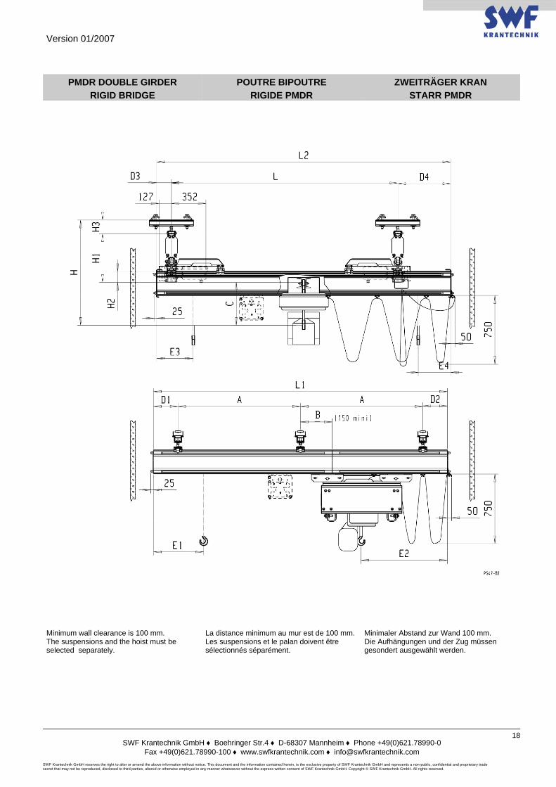
PMDR DOUBLE GIRDER RIGID BRIDGE
POUTRE BIPOUTRE RIGIDE PMDR
ZWEITRÄGER KRAN STARR PMDR
Minimum wall clearance is 100 mm. The suspensions and the hoist must be selected separately.
La distance minimum au mur est de 100 mm.Les suspensions et le palan doivent être sélectionnés séparément.
Minimaler Abstand zur Wand 100 mm. Die Aufhängungen und der Zug müssen gesondert ausgewählt werden.
Version 01/2007
SWF Krantechnik GmbH ♦ Boehringer Str.4 ♦ D-68307 Mannheim ♦ Phone +49(0)621.78990-0
Fax +49(0)621.78990-100 ♦ www.swfkrantechnik.com ♦ [email protected] SWF Krantechnik GmbH reserves the right to alter or amend the above information without notice. This document and the information contained herein, is the exclusive property of SWF Krantechnik GmbH and represents a non-public, confidential and proprietary trade secret that may not be reproduced, disclosed to third parties, altered or otherwise employed in any manner whatsoever without the express written consent of SWF Krantechnik GmbH. Copyright © SWF Krantechnik GmbH. All rights reserved.
19
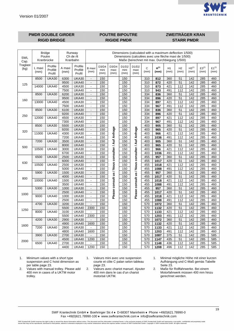
PMDR DOUBLE GIRDER RIGID BRIDGE
POUTRE BIPOUTRE RIGIDE PMDR
ZWEITRÄGER KRAN STARR PMDR
SWL Cap.
Traglast (kg)
Bridge Poutre
Kranbrücke
Runway Ch de rlt
Kranbahn
Dimensions (calculated with a maximum deflection 1/500) Dimensions (calculées avec une flèche maxi de 1/500)
Maße (berechnet mit max. Durchbiegung 1/500)
L maxi (mm)
Profile Profilé Profil
A maxi (mm)
Profile Profilé Profil
B maxi (mm)
D3/D4 mini (mm)
D3/D4 maxi (mm)
D1/D2 mini (mm)
D1/D2 maxi (mm)
C (mm)
H(1) (mm)
H1 (mm)
H2 (mm)
H3(1) (mm)
E3(2) (mm)
E1(2) (mm)
125
8500 UKA30 6300 UKA30 - 150
Plea
se c
onsu
lt us
/ N
ous
cons
ulte
r / A
uf A
nfra
ge
150
Plea
se c
onsu
lt us
/ N
ous
cons
ulte
r / A
uf A
nfra
ge
310 812 360 51 142 285 460 9500 UKA40 - 150 150 310 872 420 51 142 285 460
14000 UKA40 4500 UKA30 - 150 150 310 873 421 112 142 285 460 7500 UKA40 - 150 150 310 943 491 112 142 285 460
160
8500 UKA30 6200 UKA30 - 150 150 334 836 360 51 142 285 460 9500 UKA40 - 150 150 334 896 420 51 142 285 460
13000 UKA40 4500 UKA30 - 150 150 334 897 421 112 142 285 460 7500 UKA40 - 150 150 334 967 491 112 142 285 460
250
8500 UKA30 6100 UKA30 - 150 150 334 836 360 51 142 285 460 9200 UKA40 - 150 150 334 896 420 51 142 285 460
12000 UKA40 4500 UKA30 - 150 150 334 897 421 112 142 285 460 7300 UKA40 - 150 150 334 967 491 112 142 285 460
320
8500 UKA30 5500 UKA30 - 150 150 403 905 360 51 142 285 460 9200 UKA40 - 150 150 403 965 420 51 142 285 460
11000 UKA40 4300 UKA30 - 150 150 403 966 421 112 142 285 460 7200 UKA40 - 150 150 403 1036 491 112 142 285 460
500
7200 UKA30 3500 UKA30 - 150 150 403 905 360 51 142 285 460 8000 UKA40 - 150 150 403 965 420 51 142 285 460
10500 UKA40 3000 UKA30 - 150 150 403 966 421 112 142 285 460 6700 UKA40 - 150 150 403 1036 491 112 142 285 460
630
6500 UKA30 2500 UKA30 - 150 150 455 957 360 51 142 285 460 6000 UKA40 - 150 150 455 1017 420 51 142 285 460
10500 UKA40 2500 UKA30 - 150 150 455 1018 421 112 142 285 460 5000 UKA40 - 150 150 455 1088 491 112 142 285 460
800
5900 UKA30 1500 UKA30 - 150 150 455 957 360 51 142 285 460 4000 UKA40 - 150 150 455 1017 420 51 142 285 460
10000 UKA40 1500 UKA30 - 150 150 455 1018 421 112 142 285 460 3500 UKA40 - 150 150 455 1088 491 112 142 285 460
1000
5300 UKA30 1000 UKA30 - 150 150 455 957 360 51 142 285 460 2500 UKA40 - 150 150 455 1017 420 51 142 285 460
9000 UKA40 1000 UKA30 - 150 150 455 1018 421 112 142 285 460 2500 UKA40 - 150 150 455 1088 491 112 142 285 460
1250
4700 UKA30 3200 UKA30 - 150 150 570 1072 360 51 142 285 460 5500 UKA40 2300 150 150 570 1132 420 51 142 285 460
8000 UKA40 3100 UKA30 - 150 150 570 1133 421 112 142 285 460 5500 UKA40 2300 150 150 570 1203 491 112 142 285 460
1600
4200 UKA30 2900 UKA30 - 150 150 570 1072 360 51 142 285 460 4900 UKA40 1600 150 150 570 1132 420 51 142 285 460
7200 UKA40 2800 UKA30 - 150 150 570 1133 421 112 142 285 460 4800 UKA40 1600 150 150 570 1203 491 112 142 285 460
2000
3900 UKA30 2700 UKA30 - 150 150 570 1087 375 51 142 285 585 4500 UKA40 1200 150 150 570 1147 435 51 142 285 585
6500 UKA40 2700 UKA30 - 150 150 570 1148 436 112 142 285 585 4400 UKA40 1200 150 150 570 1208 496 112 142 285 585
1. Minimum values with a short type
suspension and C hoist dimension as per table page 23.
2. Values with manual trolley. Please add 400 mm in cases of a UKTM motor trolley.
1. Valeurs mini avec une suspension courte et côte C palan selon tableau page 23.
2. Valeurs avec chariot manuel. Ajouter 400 mm dans le cas d’un chariot motorisé UKTM.
1. Minimal mögliche Höhe mit einer kurzen Aufhängung und C-Maß gemäs Tabelle Seite 23.
2. Maße für Rollfahrwerke. Bei einem Motorfahrwerk müssen 400 mm hinzu gerechnet werden.
Version 01/2007
SWF Krantechnik GmbH ♦ Boehringer Str.4 ♦ D-68307 Mannheim ♦ Phone +49(0)621.78990-0
Fax +49(0)621.78990-100 ♦ www.swfkrantechnik.com ♦ [email protected] SWF Krantechnik GmbH reserves the right to alter or amend the above information without notice. This document and the information contained herein, is the exclusive property of SWF Krantechnik GmbH and represents a non-public, confidential and proprietary trade secret that may not be reproduced, disclosed to third parties, altered or otherwise employed in any manner whatsoever without the express written consent of SWF Krantechnik GmbH. Copyright © SWF Krantechnik GmbH. All rights reserved.
20
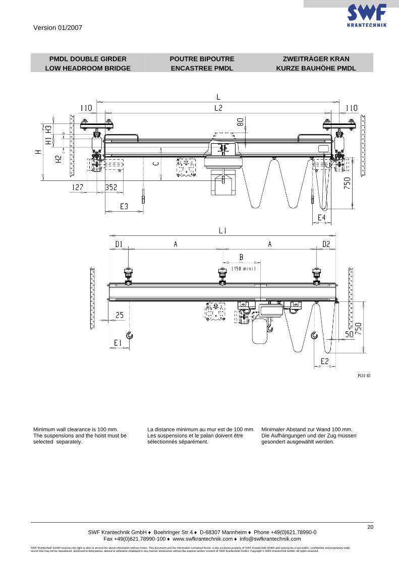
PMDL DOUBLE GIRDER LOW HEADROOM BRIDGE
POUTRE BIPOUTRE ENCASTREE PMDL
ZWEITRÄGER KRAN KURZE BAUHÖHE PMDL
Minimum wall clearance is 100 mm. The suspensions and the hoist must be selected separately.
La distance minimum au mur est de 100 mm.Les suspensions et le palan doivent être sélectionnés séparément.
Minimaler Abstand zur Wand 100 mm. Die Aufhängungen und der Zug müssen gesondert ausgewählt werden.
Version 01/2007
SWF Krantechnik GmbH ♦ Boehringer Str.4 ♦ D-68307 Mannheim ♦ Phone +49(0)621.78990-0
Fax +49(0)621.78990-100 ♦ www.swfkrantechnik.com ♦ [email protected] SWF Krantechnik GmbH reserves the right to alter or amend the above information without notice. This document and the information contained herein, is the exclusive property of SWF Krantechnik GmbH and represents a non-public, confidential and proprietary trade secret that may not be reproduced, disclosed to third parties, altered or otherwise employed in any manner whatsoever without the express written consent of SWF Krantechnik GmbH. Copyright © SWF Krantechnik GmbH. All rights reserved.
21
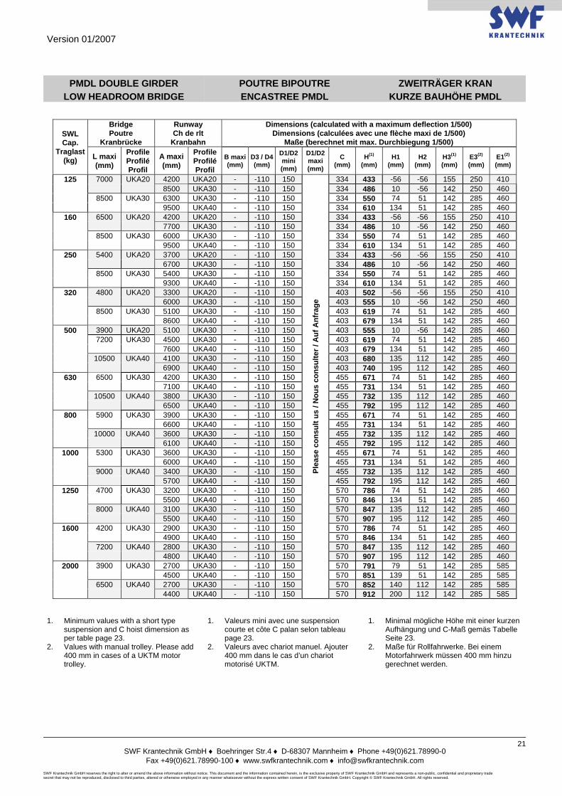
PMDL DOUBLE GIRDER LOW HEADROOM BRIDGE
POUTRE BIPOUTRE ENCASTREE PMDL
ZWEITRÄGER KRAN KURZE BAUHÖHE PMDL
SWL Cap.
Traglast (kg)
Bridge Poutre
Kranbrücke
Runway Ch de rlt
Kranbahn
Dimensions (calculated with a maximum deflection 1/500) Dimensions (calculées avec une flèche maxi de 1/500)
Maße (berechnet mit max. Durchbiegung 1/500)
L maxi (mm)
Profile Profilé Profil
A maxi (mm)
Profile Profilé Profil
B maxi(mm)
D3 / D4 (mm)
D1/D2 mini (mm)
D1/D2 maxi (mm)
C (mm)
H(1) (mm)
H1 (mm)
H2 (mm)
H3(1) (mm)
E3(2) (mm)
E1(2) (mm)
125 7000 UKA20 4200 UKA20 - -110 150
Plea
se c
onsu
lt us
/ N
ous
cons
ulte
r / A
uf A
nfra
ge
334 433 -56 -56 155 250 410 8500 UKA30 - -110 150 334 486 10 -56 142 250 460 8500 UKA30 6300 UKA30 - -110 150 334 550 74 51 142 285 460 9500 UKA40 - -110 150 334 610 134 51 142 285 460
160 6500 UKA20 4200 UKA20 - -110 150 334 433 -56 -56 155 250 410 7700 UKA30 - -110 150 334 486 10 -56 142 250 460 8500 UKA30 6000 UKA30 - -110 150 334 550 74 51 142 285 460 9500 UKA40 - -110 150 334 610 134 51 142 285 460
250 5400 UKA20 3700 UKA20 - -110 150 334 433 -56 -56 155 250 410 6700 UKA30 - -110 150 334 486 10 -56 142 250 460 8500 UKA30 5400 UKA30 - -110 150 334 550 74 51 142 285 460 9300 UKA40 - -110 150 334 610 134 51 142 285 460
320 4800 UKA20 3300 UKA20 - -110 150 403 502 -56 -56 155 250 410 6000 UKA30 - -110 150 403 555 10 -56 142 250 460 8500 UKA30 5100 UKA30 - -110 150 403 619 74 51 142 285 460 8600 UKA40 - -110 150 403 679 134 51 142 285 460
500 3900 UKA20 5100 UKA30 - -110 150 403 555 10 -56 142 285 460 7200 UKA30 4500 UKA30 - -110 150 403 619 74 51 142 285 460 7600 UKA40 - -110 150 403 679 134 51 142 285 460 10500 UKA40 4100 UKA30 - -110 150 403 680 135 112 142 285 460 6900 UKA40 - -110 150 403 740 195 112 142 285 460
630 6500 UKA30 4200 UKA30 - -110 150 455 671 74 51 142 285 460 7100 UKA40 - -110 150 455 731 134 51 142 285 460 10500 UKA40 3800 UKA30 - -110 150 455 732 135 112 142 285 460 6500 UKA40 - -110 150 455 792 195 112 142 285 460
800 5900 UKA30 3900 UKA30 - -110 150 455 671 74 51 142 285 460 6600 UKA40 - -110 150 455 731 134 51 142 285 460 10000 UKA40 3600 UKA30 - -110 150 455 732 135 112 142 285 460 6100 UKA40 - -110 150 455 792 195 112 142 285 460
1000 5300 UKA30 3600 UKA30 - -110 150 455 671 74 51 142 285 460 6000 UKA40 - -110 150 455 731 134 51 142 285 460 9000 UKA40 3400 UKA30 - -110 150 455 732 135 112 142 285 460 5700 UKA40 - -110 150 455 792 195 112 142 285 460
1250 4700 UKA30 3200 UKA30 - -110 150 570 786 74 51 142 285 460 5500 UKA40 - -110 150 570 846 134 51 142 285 460 8000 UKA40 3100 UKA30 - -110 150 570 847 135 112 142 285 460 5500 UKA40 - -110 150 570 907 195 112 142 285 460
1600 4200 UKA30 2900 UKA30 - -110 150 570 786 74 51 142 285 460 4900 UKA40 - -110 150 570 846 134 51 142 285 460 7200 UKA40 2800 UKA30 - -110 150 570 847 135 112 142 285 460 4800 UKA40 - -110 150 570 907 195 112 142 285 460
2000 3900 UKA30 2700 UKA30 - -110 150 570 791 79 51 142 285 585 4500 UKA40 - -110 150 570 851 139 51 142 285 585 6500 UKA40 2700 UKA30 - -110 150 570 852 140 112 142 285 585 4400 UKA40 - -110 150 570 912 200 112 142 285 585
1. Minimum values with a short type
suspension and C hoist dimension as per table page 23.
2. Values with manual trolley. Please add 400 mm in cases of a UKTM motor trolley.
1. Valeurs mini avec une suspension courte et côte C palan selon tableau page 23.
2. Valeurs avec chariot manuel. Ajouter 400 mm dans le cas d’un chariot motorisé UKTM.
1. Minimal mögliche Höhe mit einer kurzen Aufhängung und C-Maß gemäs Tabelle Seite 23.
2. Maße für Rollfahrwerke. Bei einem Motorfahrwerk müssen 400 mm hinzu gerechnet werden.
Version 01/2007
SWF Krantechnik GmbH ♦ Boehringer Str.4 ♦ D-68307 Mannheim ♦ Phone +49(0)621.78990-0
Fax +49(0)621.78990-100 ♦ www.swfkrantechnik.com ♦ [email protected] SWF Krantechnik GmbH reserves the right to alter or amend the above information without notice. This document and the information contained herein, is the exclusive property of SWF Krantechnik GmbH and represents a non-public, confidential and proprietary trade secret that may not be reproduced, disclosed to third parties, altered or otherwise employed in any manner whatsoever without the express written consent of SWF Krantechnik GmbH. Copyright © SWF Krantechnik GmbH. All rights reserved.
22
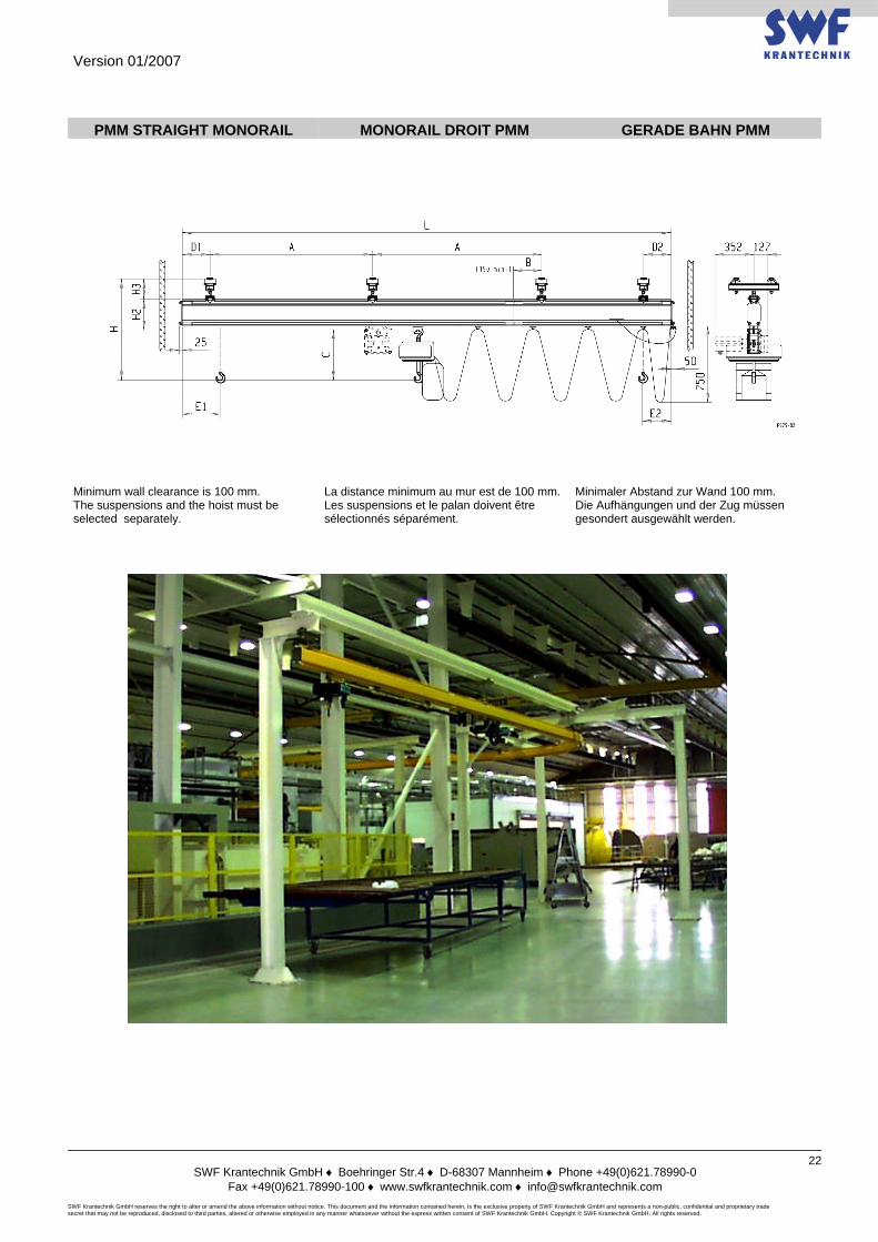
PMM STRAIGHT MONORAIL MONORAIL DROIT PMM GERADE BAHN PMM
Minimum wall clearance is 100 mm. The suspensions and the hoist must be selected separately.
La distance minimum au mur est de 100 mm.Les suspensions et le palan doivent être sélectionnés séparément.
Minimaler Abstand zur Wand 100 mm. Die Aufhängungen und der Zug müssen gesondert ausgewählt werden.
Version 01/2007
SWF Krantechnik GmbH ♦ Boehringer Str.4 ♦ D-68307 Mannheim ♦ Phone +49(0)621.78990-0
Fax +49(0)621.78990-100 ♦ www.swfkrantechnik.com ♦ [email protected] SWF Krantechnik GmbH reserves the right to alter or amend the above information without notice. This document and the information contained herein, is the exclusive property of SWF Krantechnik GmbH and represents a non-public, confidential and proprietary trade secret that may not be reproduced, disclosed to third parties, altered or otherwise employed in any manner whatsoever without the express written consent of SWF Krantechnik GmbH. Copyright © SWF Krantechnik GmbH. All rights reserved.
23
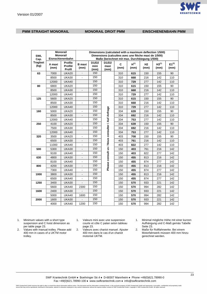
PMM STRAIGHT MONORAIL MONORAIL DROIT PMM EINSCHIENENBAHN PMM
SWL Cap.
Traglast (kg)
Monorail Monorail
Eisnschienenbahn
Dimensions (calculated with a maximum deflection 1/500) Dimensions (calculées avec une flèche maxi de 1/500)
Maße (berechnet mit max. Durchbiegung 1/500)
A maxi (mm)
Profile Profilé Profil
B maxi (mm)
D1/D2 mini (mm)
D1/D2 maxi (mm)
C (mm)
H(1) (mm)
H2 (mm)
H3(1) (mm)
E1(2) (mm)
63 7000 UKA20 - 150
Plea
se c
onsu
lt us
/ N
ous
cons
ulte
r / A
uf A
nfra
ge
310 615 150 155 90 8500 UKA30 - 150 310 668 216 142 110 12000 UKA40 150 310 729 277 142 110
80 6800 UKA20 150 310 615 150 155 90 8500 UKA30 - 150 310 668 216 142 110 12000 UKA40 150 310 729 277 142 110
125 5600 UKA20 150 310 615 150 155 90 8500 UKA30 - 150 310 668 216 142 110 12000 UKA40 150 310 729 277 142 110
160 5000 UKA20 - 150 334 639 150 155 90 8500 UKA30 - 150 334 692 216 142 110 12000 UKA40 150 334 753 277 142 110
250 4100 UKA20 - 150 334 639 150 155 90 7500 UKA30 - 150 334 692 216 142 110 12000 UKA40 150 334 753 277 142 110
320 3500 UKA20 - 150 403 708 150 155 90 6500 UKA30 - 150 403 761 216 142 110 11000 UKA40 - 150 403 822 277 142 110
500 5300 UKA30 - 150 150 403 761 216 142 9100 UKA40 - 150 150 403 822 277 142
630 4800 UKA30 - 150 150 455 813 216 142 8100 UKA40 - 150 150 455 874 277 142
800 4200 UKA30 - 150 150 455 813 216 142 7300 UKA40 - 150 150 455 874 277 142
1000 3800 UKA30 - 150 150 455 813 216 142 6500 UKA40 - 150 150 455 874 277 142
1250 3400 UKA30 - 150 150 570 933 221 142 5600 UKA40 2300 150 150 570 994 282 142
1600 2400 UKA30 - 150 150 570 933 221 142 5000 UKA40 1600 150 150 570 994 282 142
2000 1600 UKA30 - 150 150 570 933 221 142 4000 UKA40 1200 150 150 570 994 282 142
1. Minimum values with a short type
suspension and C hoist dimension as per table page 23.
2. Values with manual trolley. Please add 400 mm in cases of a UKTM motor trolley.
1. Valeurs mini avec une suspension courte et côte C palan selon tableau page 23.
2. Valeurs avec chariot manuel. Ajouter 400 mm dans le cas d’un chariot motorisé UKTM.
1. Minimal mögliche Höhe mit einer kurzen Aufhängung und C-Maß gemäs Tabelle Seite 23.
2. Maße für Rollfahrwerke. Bei einem Motorfahrwerk müssen 400 mm hinzu gerechnet werden.

Version 01/2007
SWF Krantechnik GmbH ♦ Boehringer Str.4 ♦ D-68307 Mannheim ♦ Phone +49(0)621.78990-0
Fax +49(0)621.78990-100 ♦ www.swfkrantechnik.com ♦ [email protected] SWF Krantechnik GmbH reserves the right to alter or amend the above information without notice. This document and the information contained herein, is the exclusive property of SWF Krantechnik GmbH and represents a non-public, confidential and proprietary trade secret that may not be reproduced, disclosed to third parties, altered or otherwise employed in any manner whatsoever without the express written consent of SWF Krantechnik GmbH. Copyright © SWF Krantechnik GmbH. All rights reserved.
24
NOTES / NOTIZEN
Version 01/2007
SWF Krantechnik GmbH ♦ Boehringer Str.4 ♦ D-68307 Mannheim ♦ Phone +49(0)621.78990-0
Fax +49(0)621.78990-100 ♦ www.swfkrantechnik.com ♦ [email protected] SWF Krantechnik GmbH reserves the right to alter or amend the above information without notice. This document and the information contained herein, is the exclusive property of SWF Krantechnik GmbH and represents a non-public, confidential and proprietary trade secret that may not be reproduced, disclosed to third parties, altered or otherwise employed in any manner whatsoever without the express written consent of SWF Krantechnik GmbH. Copyright © SWF Krantechnik GmbH. All rights reserved.
25
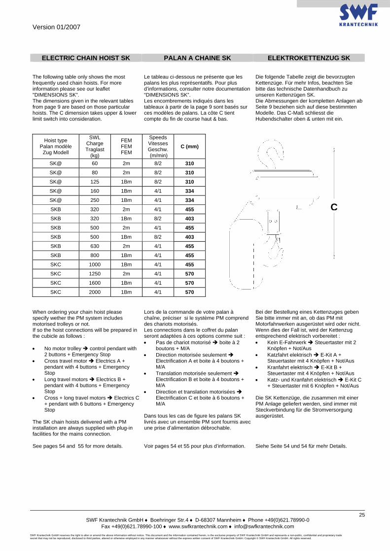
ELECTRIC CHAIN HOIST SK PALAN A CHAINE SK ELEKTROKETTENZUG SK
The following table only shows the most frequently used chain hoists. For more information please see our leaflet "DIMENSIONS SK”. The dimensions given in the relevant tables from page 9 are based on those particular hoists. The C dimension takes upper & lower limit switch into consideration.
Le tableau ci-dessous ne présente que les palans les plus représentatifs. Pour plus d’informations, consulter notre documentation “DIMENSIONS SK”. Les encombrements indiqués dans les tableaux à partir de la page 9 sont basés sur ces modèles de palans. La côte C tient compte du fin de course haut & bas.
Die folgende Tabelle zeigt die bevorzugten Kettenzüge. Für mehr Infos, beachten Sie bitte das technische Datenhandbuch zu unseren Kettenzügen SK. Die Abmessungen der kompletten Anlagen ab Seite 9 beziehen sich auf diese bestimmten Modelle. Das C-Maß schliesst die Hubendschalter oben & unten mit ein.
Hoist type Palan modèle
Zug Modell
SWL Charge Traglast
(kg)
FEM FEM FEM
Speeds Vitesses Geschw. (m/min)
C (mm)
SK@ 60 2m 8/2 310
SK@ 80 2m 8/2 310
SK@ 125 1Bm 8/2 310
SK@ 160 1Bm 4/1 334
SK@ 250 1Bm 4/1 334
SKB 320 2m 4/1 455
SKB 320 1Bm 8/2 403
SKB 500 2m 4/1 455
SKB 500 1Bm 8/2 403
SKB 630 2m 4/1 455
SKB 800 1Bm 4/1 455
SKC 1000 1Bm 4/1 455
SKC 1250 2m 4/1 570
SKC 1600 1Bm 4/1 570
SKC 2000 1Bm 4/1 570 When ordering your chain hoist please specify wether the PM system includes motorised trolleys or not. If so the hoist connections will be prepared in the cubicle as follows : • No motor trolley control pendant with
2 buttons + Emergency Stop • Cross travel motor Electrics A +
pendant with 4 buttons + Emergency Stop
• Long travel motors Electrics B + pendant with 4 buttons + Emergency Stop
• Cross + long travel motors Electrics C + pendant with 6 buttons + Emergency Stop
The SK chain hoists delivered with a PM installation are always supplied with plug-in facilities for the mains connection.
Lors de la commande de votre palan à chaîne, préciser si le système PM comprend des chariots motorisés. Les connections dans le coffret du palan seront adaptées à ces options comme suit : • Pas de chariot motorisé boite à 2
boutons + M/A • Direction motorisée seulement
Electrification A et boite à 4 boutons + M/A
• Translation motorisée seulement Electrification B et boite à 4 boutons + M/A
• Direction et translation motorisées Electrification C et boite à 6 boutons + M/A
Dans tous les cas de figure les palans SK livrés avec un ensemble PM sont fournis avec une prise d’alimentation débrochable.
Bei der Bestellung eines Kettenzuges geben Sie bitte immer mit an, ob das PM mit Motorfahrwerken ausgerüstet wird oder nicht. Wenn dies der Fall ist, wird der Kettenzug entsprechend elektrisch vorbereitet : • Kein E-Fahrwerk Steuertaster mit 2
Knöpfen + Not/Aus • Katzfahrt elektrisch E-Kit A +
Steuertaster mit 4 Knöpfen + Not/Aus • Kranfahrt elektrisch E-Kit B +
Steuertaster mit 4 Knöpfen + Not/Aus • Katz- und Kranfahrt elektrisch E-Kit C
+ Steuertaster mit 6 Knöpfen + Not/Aus
Die SK Kettenzüge, die zusammen mit einer PM Anlage geliefert werden, sind immer mit Steckverbindung für die Stromversorgung ausgerüstet.
See pages 54 and 55 for more details. Voir pages 54 et 55 pour plus d’information. Siehe Seite 54 und 54 für mehr Details.
C
Version 01/2007
SWF Krantechnik GmbH ♦ Boehringer Str.4 ♦ D-68307 Mannheim ♦ Phone +49(0)621.78990-0
Fax +49(0)621.78990-100 ♦ www.swfkrantechnik.com ♦ [email protected] SWF Krantechnik GmbH reserves the right to alter or amend the above information without notice. This document and the information contained herein, is the exclusive property of SWF Krantechnik GmbH and represents a non-public, confidential and proprietary trade secret that may not be reproduced, disclosed to third parties, altered or otherwise employed in any manner whatsoever without the express written consent of SWF Krantechnik GmbH. Copyright © SWF Krantechnik GmbH. All rights reserved.
26
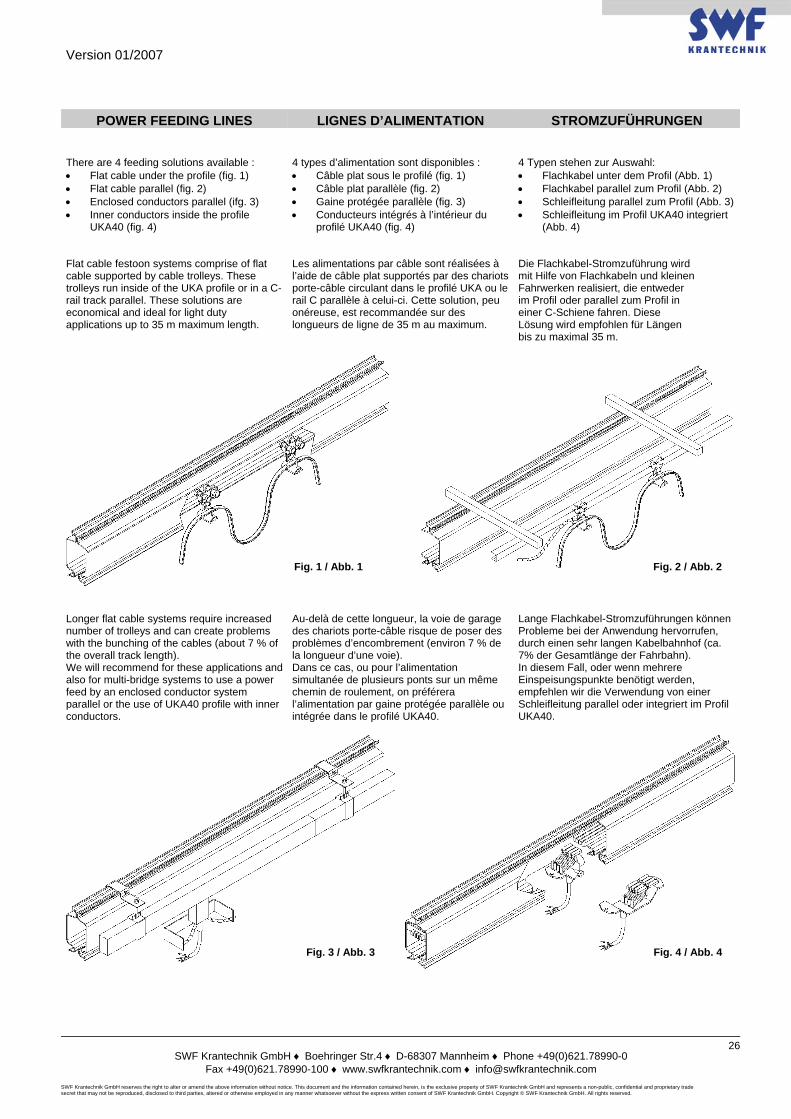
POWER FEEDING LINES LIGNES D’ALIMENTATION STROMZUFÜHRUNGEN
There are 4 feeding solutions available : • Flat cable under the profile (fig. 1) • Flat cable parallel (fig. 2) • Enclosed conductors parallel (ifg. 3) • Inner conductors inside the profile
UKA40 (fig. 4)
4 types d’alimentation sont disponibles : • Câble plat sous le profilé (fig. 1) • Câble plat parallèle (fig. 2) • Gaine protégée parallèle (fig. 3) • Conducteurs intégrés à l’intérieur du
profilé UKA40 (fig. 4)
4 Typen stehen zur Auswahl: • Flachkabel unter dem Profil (Abb. 1) • Flachkabel parallel zum Profil (Abb. 2) • Schleifleitung parallel zum Profil (Abb. 3) • Schleifleitung im Profil UKA40 integriert
(Abb. 4) Flat cable festoon systems comprise of flat cable supported by cable trolleys. These trolleys run inside of the UKA profile or in a C-rail track parallel. These solutions are economical and ideal for light duty applications up to 35 m maximum length.
Les alimentations par câble sont réalisées à l’aide de câble plat supportés par des chariots porte-câble circulant dans le profilé UKA ou le rail C parallèle à celui-ci. Cette solution, peu onéreuse, est recommandée sur des longueurs de ligne de 35 m au maximum.
Die Flachkabel-Stromzuführung wird mit Hilfe von Flachkabeln und kleinen Fahrwerken realisiert, die entweder im Profil oder parallel zum Profil in einer C-Schiene fahren. Diese Lösung wird empfohlen für Längen bis zu maximal 35 m.
Longer flat cable systems require increased number of trolleys and can create problems with the bunching of the cables (about 7 % of the overall track length). We will recommend for these applications and also for multi-bridge systems to use a power feed by an enclosed conductor system parallel or the use of UKA40 profile with inner conductors.
Au-delà de cette longueur, la voie de garage des chariots porte-câble risque de poser des problèmes d’encombrement (environ 7 % de la longueur d’une voie). Dans ce cas, ou pour l’alimentation simultanée de plusieurs ponts sur un même chemin de roulement, on préférera l’alimentation par gaine protégée parallèle ou intégrée dans le profilé UKA40.
Lange Flachkabel-Stromzuführungen können Probleme bei der Anwendung hervorrufen, durch einen sehr langen Kabelbahnhof (ca. 7% der Gesamtlänge der Fahrbahn). In diesem Fall, oder wenn mehrere Einspeisungspunkte benötigt werden, empfehlen wir die Verwendung von einer Schleifleitung parallel oder integriert im Profil UKA40.
Fig. 4 / Abb. 4Fig. 3 / Abb. 3
Fig. 1 / Abb. 1 Fig. 2 / Abb. 2
Version 01/2007
SWF Krantechnik GmbH ♦ Boehringer Str.4 ♦ D-68307 Mannheim ♦ Phone +49(0)621.78990-0
Fax +49(0)621.78990-100 ♦ www.swfkrantechnik.com ♦ [email protected] SWF Krantechnik GmbH reserves the right to alter or amend the above information without notice. This document and the information contained herein, is the exclusive property of SWF Krantechnik GmbH and represents a non-public, confidential and proprietary trade secret that may not be reproduced, disclosed to third parties, altered or otherwise employed in any manner whatsoever without the express written consent of SWF Krantechnik GmbH. Copyright © SWF Krantechnik GmbH. All rights reserved.
27
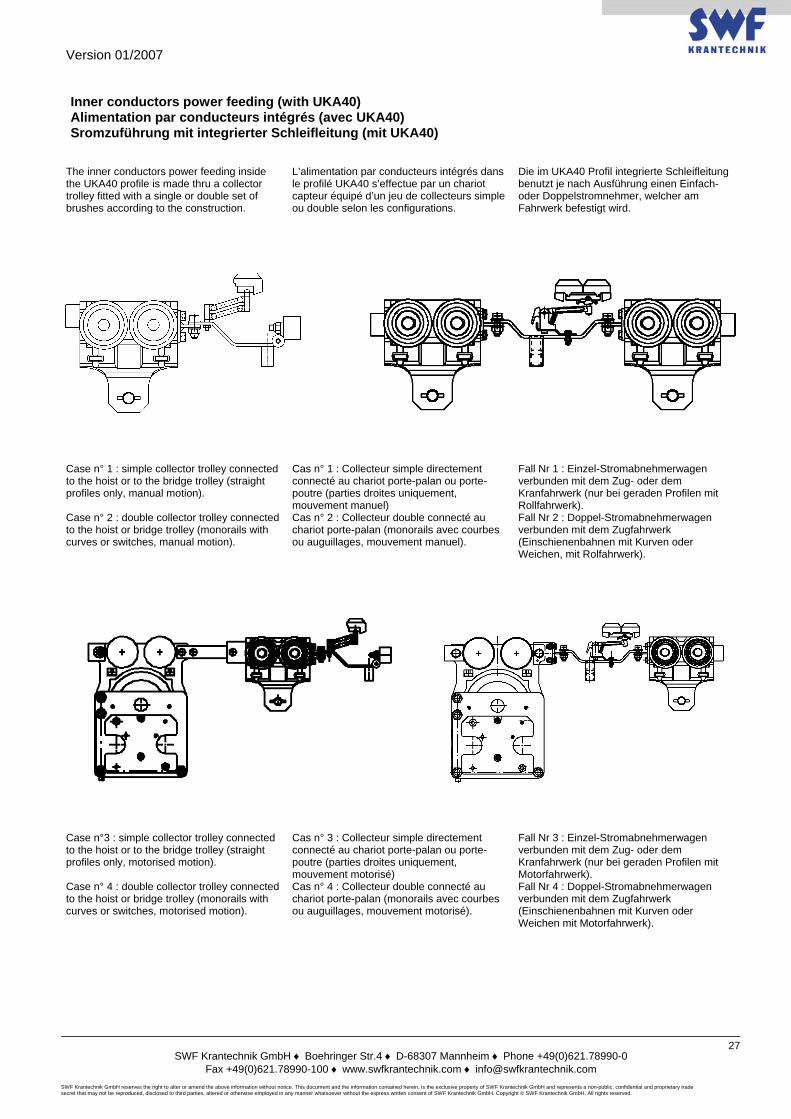
Inner conductors power feeding (with UKA40) Alimentation par conducteurs intégrés (avec UKA40) Sromzuführung mit integrierter Schleifleitung (mit UKA40)
The inner conductors power feeding inside the UKA40 profile is made thru a collector trolley fitted with a single or double set of brushes according to the construction.
L’alimentation par conducteurs intégrés dans le profilé UKA40 s’effectue par un chariot capteur équipé d’un jeu de collecteurs simple ou double selon les configurations.
Die im UKA40 Profil integrierte Schleifleitung benutzt je nach Ausführung einen Einfach- oder Doppelstromnehmer, welcher am Fahrwerk befestigt wird.
Case n° 1 : simple collector trolley connected to the hoist or to the bridge trolley (straight profiles only, manual motion).
Cas n° 1 : Collecteur simple directement connecté au chariot porte-palan ou porte-poutre (parties droites uniquement, mouvement manuel)
Fall Nr 1 : Einzel-Stromabnehmerwagen verbunden mit dem Zug- oder dem Kranfahrwerk (nur bei geraden Profilen mit Rollfahrwerk).
Case n° 2 : double collector trolley connected to the hoist or bridge trolley (monorails with curves or switches, manual motion).
Cas n° 2 : Collecteur double connecté au chariot porte-palan (monorails avec courbes ou auguillages, mouvement manuel).
Fall Nr 2 : Doppel-Stromabnehmerwagen verbunden mit dem Zugfahrwerk (Einschienenbahnen mit Kurven oder Weichen, mit Rolfahrwerk).
Case n°3 : simple collector trolley connected to the hoist or to the bridge trolley (straight profiles only, motorised motion).
Cas n° 3 : Collecteur simple directement connecté au chariot porte-palan ou porte-poutre (parties droites uniquement, mouvement motorisé)
Fall Nr 3 : Einzel-Stromabnehmerwagen verbunden mit dem Zug- oder dem Kranfahrwerk (nur bei geraden Profilen mit Motorfahrwerk).
Case n° 4 : double collector trolley connected to the hoist or bridge trolley (monorails with curves or switches, motorised motion).
Cas n° 4 : Collecteur double connecté au chariot porte-palan (monorails avec courbes ou auguillages, mouvement motorisé).
Fall Nr 4 : Doppel-Stromabnehmerwagen verbunden mit dem Zugfahrwerk (Einschienenbahnen mit Kurven oder Weichen mit Motorfahrwerk).
Version 01/2007
SWF Krantechnik GmbH ♦ Boehringer Str.4 ♦ D-68307 Mannheim ♦ Phone +49(0)621.78990-0
Fax +49(0)621.78990-100 ♦ www.swfkrantechnik.com ♦ [email protected] SWF Krantechnik GmbH reserves the right to alter or amend the above information without notice. This document and the information contained herein, is the exclusive property of SWF Krantechnik GmbH and represents a non-public, confidential and proprietary trade secret that may not be reproduced, disclosed to third parties, altered or otherwise employed in any manner whatsoever without the express written consent of SWF Krantechnik GmbH. Copyright © SWF Krantechnik GmbH. All rights reserved.
28
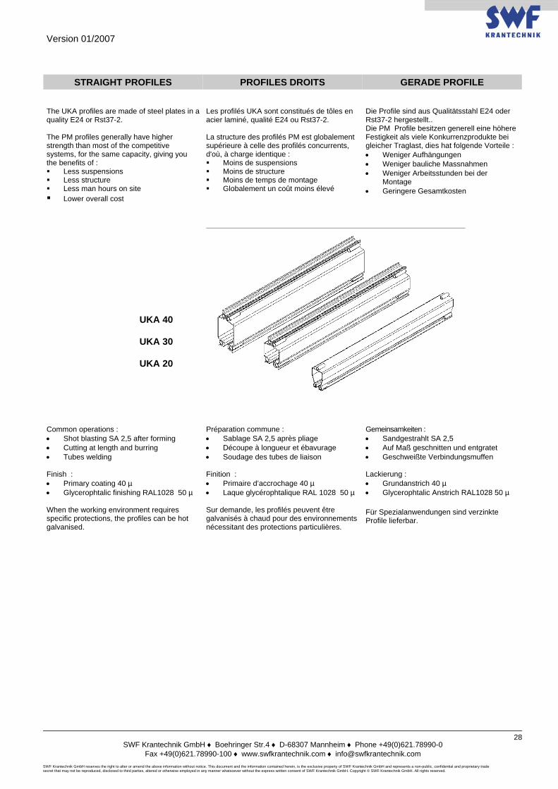
STRAIGHT PROFILES PROFILES DROITS GERADE PROFILE The UKA profiles are made of steel plates in a quality E24 or Rst37-2. The PM profiles generally have higher strength than most of the competitive systems, for the same capacity, giving you the benefits of : Less suspensions Less structure Less man hours on site Lower overall cost
Les profilés UKA sont constitués de tôles en acier laminé, qualité E24 ou Rst37-2. La structure des profilés PM est globalement supérieure à celle des profilés concurrents, d'où, à charge identique : Moins de suspensions Moins de structure Moins de temps de montage Globalement un coût moins élevé
Die Profile sind aus Qualitätsstahl E24 oder Rst37-2 hergestellt.. Die PM Profile besitzen generell eine höhere Festigkeit als viele Konkurrenzprodukte bei gleicher Traglast, dies hat folgende Vorteile : • Weniger Aufhängungen • Weniger bauliche Massnahmen • Weniger Arbeitsstunden bei der
Montage • Geringere Gesamtkosten
UKA 40
UKA 30
UKA 20
Common operations : • Shot blasting SA 2,5 after forming • Cutting at length and burring • Tubes welding Finish : • Primary coating 40 µ • Glycerophtalic finishing RAL1028 50 µ When the working environment requires specific protections, the profiles can be hot galvanised.
Préparation commune : • Sablage SA 2,5 après pliage • Découpe à longueur et ébavurage • Soudage des tubes de liaison Finition : • Primaire d’accrochage 40 µ • Laque glycérophtalique RAL 1028 50 µ Sur demande, les profilés peuvent être galvanisés à chaud pour des environnements nécessitant des protections particulières.
Gemeinsamkeiten : • Sandgestrahlt SA 2,5 • Auf Maß geschnitten und entgratet • Geschweißte Verbindungsmuffen
Lackierung : • Grundanstrich 40 µ • Glycerophtalic Anstrich RAL1028 50 µ Für Spezialanwendungen sind verzinkte Profile lieferbar.
Version 01/2007
SWF Krantechnik GmbH ♦ Boehringer Str.4 ♦ D-68307 Mannheim ♦ Phone +49(0)621.78990-0
Fax +49(0)621.78990-100 ♦ www.swfkrantechnik.com ♦ [email protected] SWF Krantechnik GmbH reserves the right to alter or amend the above information without notice. This document and the information contained herein, is the exclusive property of SWF Krantechnik GmbH and represents a non-public, confidential and proprietary trade secret that may not be reproduced, disclosed to third parties, altered or otherwise employed in any manner whatsoever without the express written consent of SWF Krantechnik GmbH. Copyright © SWF Krantechnik GmbH. All rights reserved.
29
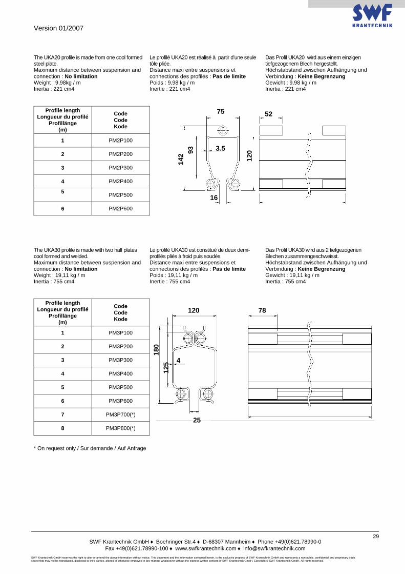
The UKA20 profile is made from one cool formed steel plate. Maximum distance between suspension and connection : No limitation Weight : 9,98kg / m Inertia : 221 cm4
Le profilé UKA20 est réalisé à partir d’une seule tôle pliée. Distance maxi entre suspensions et connections des profilés : Pas de limite Poids : 9,98 kg / m Inertie : 221 cm4
Das Profil UKA20 wird aus einem einzigen tiefgezogenem Blech hergestellt. Höchstabstand zwischen Aufhängung und Verbindung : Keine Begrenzung Gewicht : 9,98 kg / m Inertia : 221 cm4
Profile length Longueur du profilé
Profillänge (m)
Code Code Kode
1 PM2P100
2 PM2P200
3 PM2P300
4 PM2P400
5 PM2P500
6 PM2P600
The UKA30 profile is made with two half plates cool formed and welded. Maximum distance between suspension and connection : No limitation Weight : 19,11 kg / m Inertia : 755 cm4
Le profilé UKA30 est constitué de deux demi-profilés pliés à froid puis soudés. Distance maxi entre suspensions et connections des profilés : Pas de limite Poids : 19,11 kg / m Inertie : 755 cm4
Das Profil UKA30 wird aus 2 tiefgezogenen Blechen zusammengeschweisst. Höchstabstand zwischen Aufhängung und Verbindung : Keine Begrenzung Gewicht : 19,11 kg / m Inertia : 755 cm4
Profile length Longueur du profilé
Profillänge (m)
Code Code Kode
1 PM3P100
2 PM3P200
3 PM3P300
4 PM3P400
5 PM3P500
6 PM3P600
7 PM3P700(*)
8 PM3P800(*)
* On request only / Sur demande / Auf Anfrage
75 52
3.5
1693
14
2 120
25
4
180
125
78 120
Version 01/2007
SWF Krantechnik GmbH ♦ Boehringer Str.4 ♦ D-68307 Mannheim ♦ Phone +49(0)621.78990-0
Fax +49(0)621.78990-100 ♦ www.swfkrantechnik.com ♦ [email protected] SWF Krantechnik GmbH reserves the right to alter or amend the above information without notice. This document and the information contained herein, is the exclusive property of SWF Krantechnik GmbH and represents a non-public, confidential and proprietary trade secret that may not be reproduced, disclosed to third parties, altered or otherwise employed in any manner whatsoever without the express written consent of SWF Krantechnik GmbH. Copyright © SWF Krantechnik GmbH. All rights reserved.
30
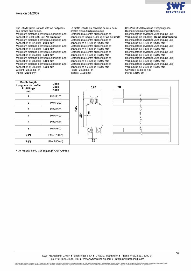
The UKA40 profile is made with two half plates cool formed and welded. Maximum distance between suspension and connection until 1000 kg : No limitation Maximum distance between suspension and connection at 1200 kg : 2300 mm Maximum distance between suspension and connection at 1400 kg : 1900 mm Maximum distance between suspension and connection at 1600 kg : 1600 mm Maximum distance between suspension and connection at 1800 kg : 1400 mm Maximum distance between suspension and connection at 2000 kg : 1000 mm Weight : 28,88 kg / m Inertia : 2198 cm4
Le profilé UKA40 est constitué de deux demi-profilés pliés à froid puis soudés. Distance maxi entre suspensions et connections jusque 1000 kg : Pas de limite Distance maxi entre suspensions et connections à 1200 kg : 2300 mm Distance maxi entre suspensions et connections à 1400 kg : 1900 mm Distance maxi entre suspensions et connections à 1600 kg : 1600 mm Distance maxi entre suspensions et connections à 1800 kg : 1400 mm Distance maxi entre suspensions et connections à 2000 kg : 1000 mm Poids : 28,88 kg / m Inertie : 2198 cm4
Das Profil UKA40 wird aus 2 tiefgezogenen Blechen zusammengeschweisst. Höchstabstand zwischen Aufhängung und Verbindung bis 1000 kg : Keine Begrenzung Höchstabstand zwischen Aufhängung und Verbindung bei 1200 kg : 2300 mm Höchstabstand zwischen Aufhängung und Verbindung bei 1400 kg : 1900 mm Höchstabstand zwischen Aufhängung und Verbindung bei 1600 kg : 1600 mm Höchstabstand zwischen Aufhängung und Verbindung bei 1800 kg : 1400 mm Höchstabstand zwischen Aufhängung und Verbindung bei 2000 kg : 1000 mm Gewicht : 28,88 kg / m Inertia : 2198 cm4
Profile length Longueur du profilé
Profillänge (m)
Code Code Kode
1 PM4P100
2 PM4P200
3 PM4P300
4 PM4P400
5 PM4P500
6 PM4P600
7 (*) PM4P700 (*)
8 (*) PM4P800 (*)
* On request only / Sur demande / Auf Anfrage
124 78
245
184 5
25
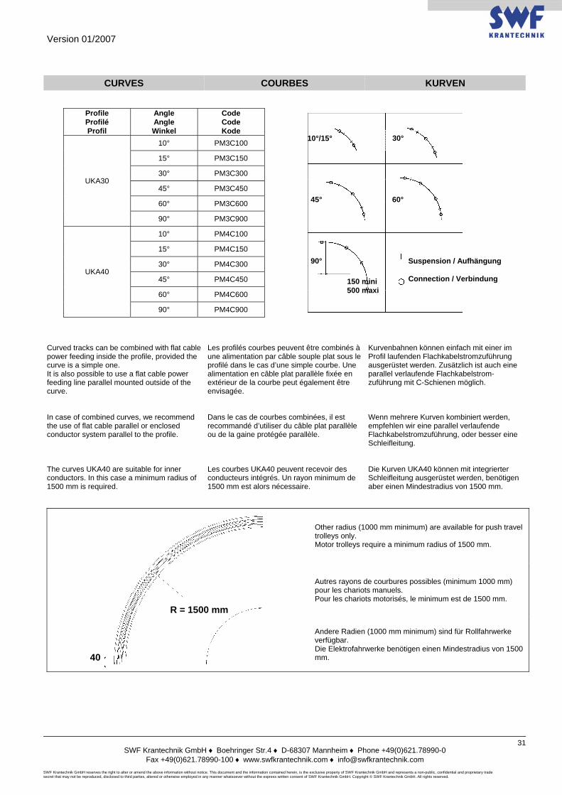
Version 01/2007
SWF Krantechnik GmbH ♦ Boehringer Str.4 ♦ D-68307 Mannheim ♦ Phone +49(0)621.78990-0
Fax +49(0)621.78990-100 ♦ www.swfkrantechnik.com ♦ [email protected] SWF Krantechnik GmbH reserves the right to alter or amend the above information without notice. This document and the information contained herein, is the exclusive property of SWF Krantechnik GmbH and represents a non-public, confidential and proprietary trade secret that may not be reproduced, disclosed to third parties, altered or otherwise employed in any manner whatsoever without the express written consent of SWF Krantechnik GmbH. Copyright © SWF Krantechnik GmbH. All rights reserved.
31
CURVES COURBES KURVEN
Profile Profilé Profil
Angle Angle Winkel
Code Code Kode
UKA30
10° PM3C100
15° PM3C150
30° PM3C300
45° PM3C450
60° PM3C600
90° PM3C900
UKA40
10° PM4C100
15° PM4C150
30° PM4C300
45° PM4C450
60° PM4C600
90° PM4C900 Curved tracks can be combined with flat cable power feeding inside the profile, provided the curve is a simple one. It is also possible to use a flat cable power feeding line parallel mounted outside of the curve.
Les profilés courbes peuvent être combinés à une alimentation par câble souple plat sous le profilé dans le cas d’une simple courbe. Une alimentation en câble plat parallèle fixée en extérieur de la courbe peut également être envisagée.
Kurvenbahnen können einfach mit einer im Profil laufenden Flachkabelstromzuführung ausgerüstet werden. Zusätzlich ist auch eine parallel verlaufende Flachkabelstrom-zuführung mit C-Schienen möglich.
In case of combined curves, we recommend the use of flat cable parallel or enclosed conductor system parallel to the profile.
Dans le cas de courbes combinées, il est recommandé d’utiliser du câble plat parallèle ou de la gaine protégée parallèle.
Wenn mehrere Kurven kombiniert werden, empfehlen wir eine parallel verlaufende Flachkabelstromzuführung, oder besser eine Schleifleitung.
The curves UKA40 are suitable for inner conductors. In this case a minimum radius of 1500 mm is required.
Les courbes UKA40 peuvent recevoir des conducteurs intégrés. Un rayon minimum de 1500 mm est alors nécessaire.
Die Kurven UKA40 können mit integrierter Schleifleitung ausgerüstet werden, benötigen aber einen Mindestradius von 1500 mm.
Other radius (1000 mm minimum) are available for push travel trolleys only. Motor trolleys require a minimum radius of 1500 mm.
Autres rayons de courbures possibles (minimum 1000 mm) pour les chariots manuels. Pour les chariots motorisés, le minimum est de 1500 mm.
Andere Radien (1000 mm minimum) sind für Rollfahrwerke verfügbar. Die Elektrofahrwerke benötigen einen Mindestradius von 1500 mm.
10°/15° 30°
45° 60°
90°
150 mini 500 maxi
Suspension / Aufhängung Connection / Verbindung
R = 1500 mm
40
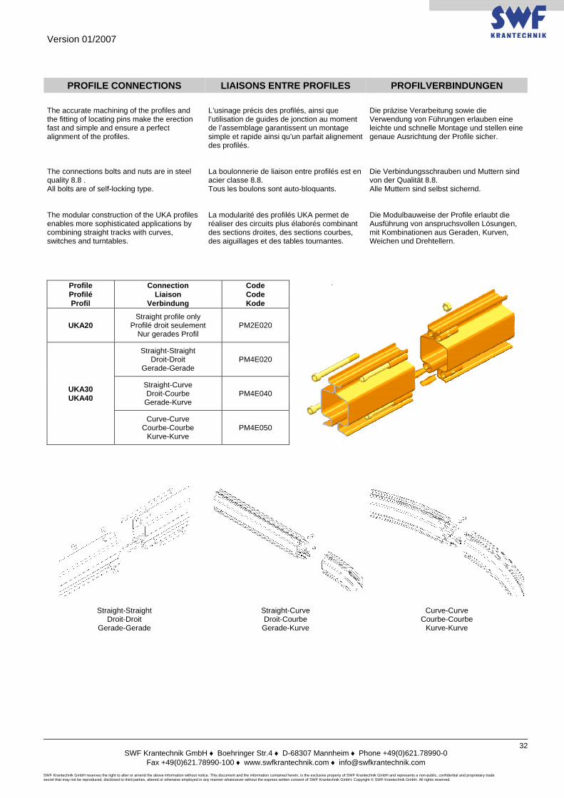
Version 01/2007
SWF Krantechnik GmbH ♦ Boehringer Str.4 ♦ D-68307 Mannheim ♦ Phone +49(0)621.78990-0
Fax +49(0)621.78990-100 ♦ www.swfkrantechnik.com ♦ [email protected] SWF Krantechnik GmbH reserves the right to alter or amend the above information without notice. This document and the information contained herein, is the exclusive property of SWF Krantechnik GmbH and represents a non-public, confidential and proprietary trade secret that may not be reproduced, disclosed to third parties, altered or otherwise employed in any manner whatsoever without the express written consent of SWF Krantechnik GmbH. Copyright © SWF Krantechnik GmbH. All rights reserved.
32
PROFILE CONNECTIONS LIAISONS ENTRE PROFILES PROFILVERBINDUNGEN
The accurate machining of the profiles and the fitting of locating pins make the erection fast and simple and ensure a perfect alignment of the profiles.
L’usinage précis des profilés, ainsi que l’utilisation de guides de jonction au moment de l’assemblage garantissent un montage simple et rapide ainsi qu’un parfait alignement des profilés.
Die präzise Verarbeitung sowie die Verwendung von Führungen erlauben eine leichte und schnelle Montage und stellen eine genaue Ausrichtung der Profile sicher.
The connections bolts and nuts are in steel quality 8.8 . All bolts are of self-locking type.
La boulonnerie de liaison entre profilés est en acier classe 8.8. Tous les boulons sont auto-bloquants.
Die Verbindungsschrauben und Muttern sind von der Qualität 8.8. Alle Muttern sind selbst sichernd.
The modular construction of the UKA profiles enables more sophisticated applications by combining straight tracks with curves, switches and turntables.
La modularité des profilés UKA permet de réaliser des circuits plus élaborés combinant des sections droites, des sections courbes, des aiguillages et des tables tournantes.
Die Modulbauweise der Profile erlaubt die Ausführung von anspruchsvollen Lösungen, mit Kombinationen aus Geraden, Kurven, Weichen und Drehtellern.
Profile Profilé Profil
Connection Liaison
Verbindung
Code Code Kode
UKA20 Straight profile only
Profilé droit seulement Nur gerades Profil
PM2E020
UKA30 UKA40
Straight-Straight Droit-Droit
Gerade-Gerade PM4E020
Straight-Curve Droit-Courbe
Gerade-Kurve PM4E040
Curve-Curve Courbe-Courbe
Kurve-Kurve PM4E050
Straight-Straight Droit-Droit
Gerade-Gerade
Straight-Curve Droit-Courbe
Gerade-Kurve
Curve-Curve Courbe-Courbe
Kurve-Kurve
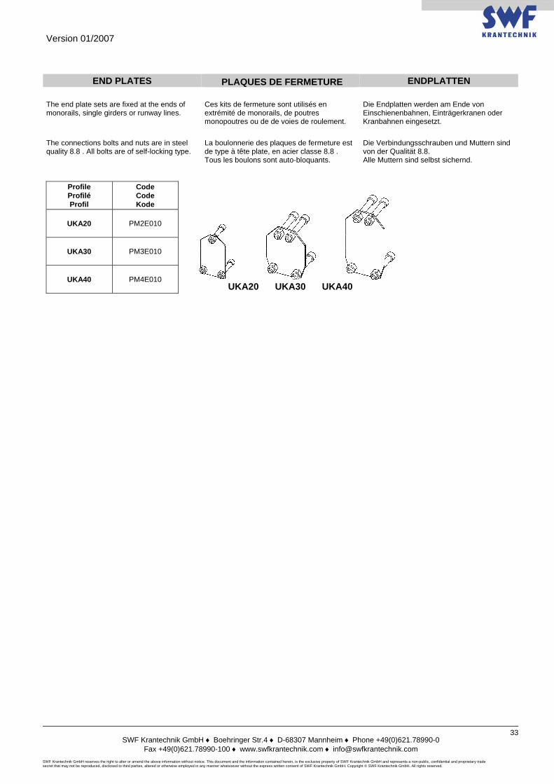
Version 01/2007
SWF Krantechnik GmbH ♦ Boehringer Str.4 ♦ D-68307 Mannheim ♦ Phone +49(0)621.78990-0
Fax +49(0)621.78990-100 ♦ www.swfkrantechnik.com ♦ [email protected] SWF Krantechnik GmbH reserves the right to alter or amend the above information without notice. This document and the information contained herein, is the exclusive property of SWF Krantechnik GmbH and represents a non-public, confidential and proprietary trade secret that may not be reproduced, disclosed to third parties, altered or otherwise employed in any manner whatsoever without the express written consent of SWF Krantechnik GmbH. Copyright © SWF Krantechnik GmbH. All rights reserved.
33
END PLATES PLAQUES DE FERMETURE ENDPLATTEN
The end plate sets are fixed at the ends of monorails, single girders or runway lines.
Ces kits de fermeture sont utilisés en extrémité de monorails, de poutres monopoutres ou de de voies de roulement.
Die Endplatten werden am Ende von Einschienenbahnen, Einträgerkranen oder Kranbahnen eingesetzt.
The connections bolts and nuts are in steel quality 8.8 . All bolts are of self-locking type.
La boulonnerie des plaques de fermeture est de type à tête plate, en acier classe 8.8 . Tous les boulons sont auto-bloquants.
Die Verbindungsschrauben und Muttern sind von der Qualität 8.8. Alle Muttern sind selbst sichernd.
Profile Profilé Profil
Code Code Kode
UKA20 PM2E010
UKA30 PM3E010
UKA40 PM4E010
UKA30 UKA40 UKA20

Version 01/2007
SWF Krantechnik GmbH ♦ Boehringer Str.4 ♦ D-68307 Mannheim ♦ Phone +49(0)621.78990-0
Fax +49(0)621.78990-100 ♦ www.swfkrantechnik.com ♦ [email protected] SWF Krantechnik GmbH reserves the right to alter or amend the above information without notice. This document and the information contained herein, is the exclusive property of SWF Krantechnik GmbH and represents a non-public, confidential and proprietary trade secret that may not be reproduced, disclosed to third parties, altered or otherwise employed in any manner whatsoever without the express written consent of SWF Krantechnik GmbH. Copyright © SWF Krantechnik GmbH. All rights reserved.
34
NOTES / NOTIZEN
Version 01/2007
SWF Krantechnik GmbH ♦ Boehringer Str.4 ♦ D-68307 Mannheim ♦ Phone +49(0)621.78990-0
Fax +49(0)621.78990-100 ♦ www.swfkrantechnik.com ♦ [email protected] SWF Krantechnik GmbH reserves the right to alter or amend the above information without notice. This document and the information contained herein, is the exclusive property of SWF Krantechnik GmbH and represents a non-public, confidential and proprietary trade secret that may not be reproduced, disclosed to third parties, altered or otherwise employed in any manner whatsoever without the express written consent of SWF Krantechnik GmbH. Copyright © SWF Krantechnik GmbH. All rights reserved.
35
SUSPENSIONS SUSPENSIONS AUFHÄNGUNGEN
The suspensions represent an important part of a light crane system. Their articulated construction minimizes the horizontal stresses transmitted to the building structure.
Les suspensions constituent un élément essentiel d’un système de manutention. Leur conception articulée minimise les efforts transmis aux structures porteuses des bâtiments.
Die Aufhängungen sind ein wichtiger Baustein des Leichtbaukranes. Die flexiblen Aufhängungen reduzieren die zu übertragenden Kräfte auf die tragende Struktur.
They are adjusted on site by a simple cutting to length according to the building configuration. They compensate for the possible unevenness of the building structure.
Elles sont réglables sur site par simple coupe à longueur selon la configuration du bâtiment. Elles permettent de compenser les irrégularités possibles de la structure porteuse.
Sie können leicht auf die passende Länge zugeschnitten werden. Sie erlauben eine leichte Anpassung an die tragende Struktur.
All parts belonging to the suspension assemblies, except threated rods, bolts and nuts, are chrome plated. The threaded rods are in steel quality 8.8.
A l’exception des tiges filetées et de la boulonnerie, toutes les pièces constitutives des suspensions sont bi-chromatées. Les tiges filetées sont en acier classe 8.8.
Bis auf die Schraubverbindungen sind sämtliche Verbindungsteile chromatiert. Die Gewindestangen sind in Qualität 8.8 ausgeführt und verzinkt.
The suspensions are available in different sizes depending on the existing structures and can be connected to any I or H beam or straight to a ceiling or a wall.
Les suspensions sont disponibles en différentes largeurs adaptées aux structures existantes et se fixent sous tout type de profilés I ou H ou directement sous plafond ou en applique.
Die Aufhängungen sind in verschiedenen Ausführungen und Breiten lieferbar, für sämtliche handelsüblichen Profile, zur Befestigung direkt unter die Decke oder als Wandbefestigungen.
The “straight” suspensions are suitable for slopes of 5 degrees maximum. The articulated suspensions are designed to be fixed under slopes between 5 and 20 degrees.
Les suspensions « droites » acceptent des pentes de 5 degrés maximum. Les suspensions « articulées » sont destinées à être fixées sous des pentes variant entre 5 et 20 degrés.
Die standardmässigen Aufhängungen sind geeignet für max. Schräge von 5°. Müssen die Aufhängungen in einer grösseren Schräge befestigt werden, können Sie die Gelenkaufhängungen benutzen von 5 bis 20°.
Each suspension is delivered individually packed with assembly instructions and parts list, ready for assembly.
Chaque suspension est emballée individuellement avec notice d’assemblage et nomenclature, prête au montage.
Jede Aufhängung ist montagefertig, einzeln verpackt, mit Montageanleitung und Stückliste.
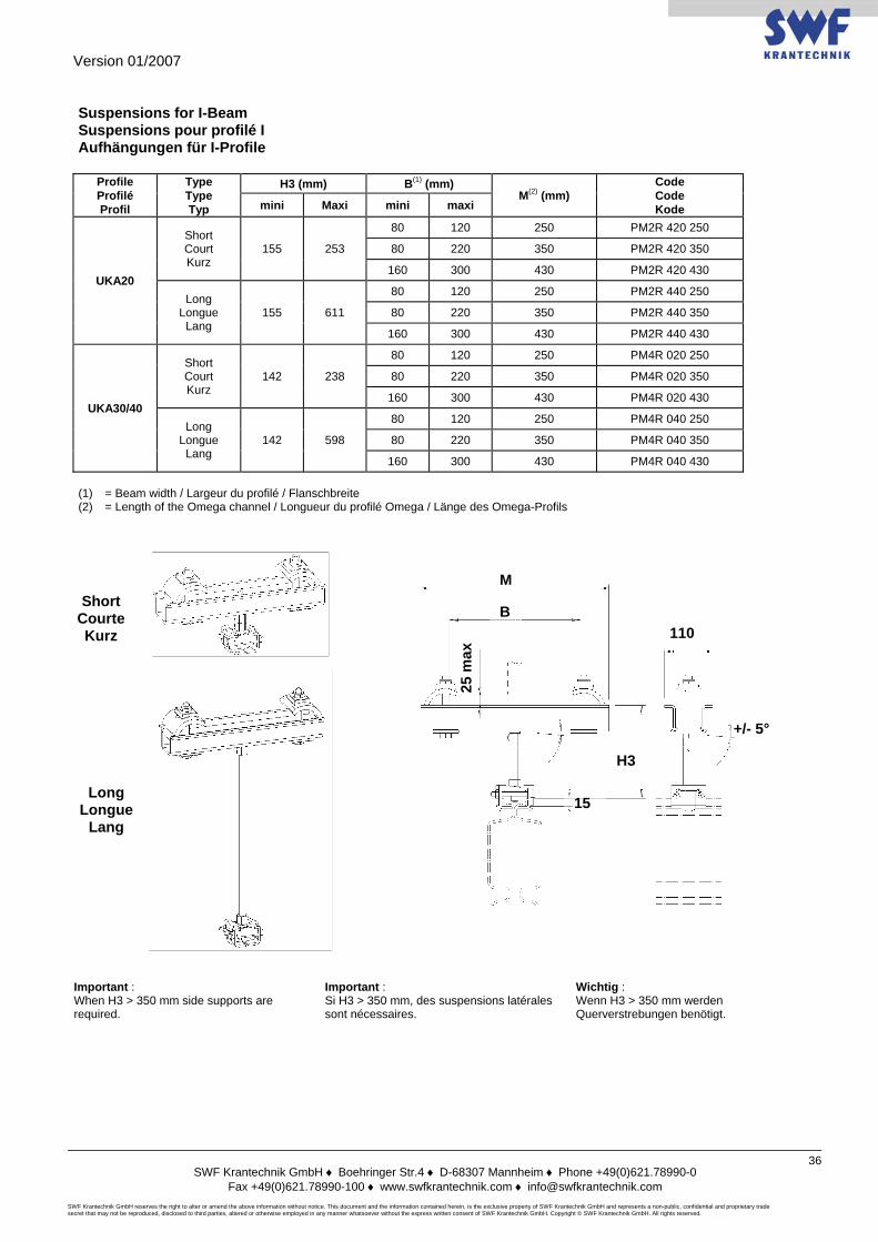
Version 01/2007
SWF Krantechnik GmbH ♦ Boehringer Str.4 ♦ D-68307 Mannheim ♦ Phone +49(0)621.78990-0
Fax +49(0)621.78990-100 ♦ www.swfkrantechnik.com ♦ [email protected] SWF Krantechnik GmbH reserves the right to alter or amend the above information without notice. This document and the information contained herein, is the exclusive property of SWF Krantechnik GmbH and represents a non-public, confidential and proprietary trade secret that may not be reproduced, disclosed to third parties, altered or otherwise employed in any manner whatsoever without the express written consent of SWF Krantechnik GmbH. Copyright © SWF Krantechnik GmbH. All rights reserved.
36
Suspensions for I-Beam Suspensions pour profilé I Aufhängungen für I-Profile
Profile Profilé Profil
Type Type Typ
H3 (mm) B(1) (mm) M(2) (mm)
Code Code Kode mini Maxi mini maxi
UKA20
Short Court Kurz
155 253
80 120 250 PM2R 420 250
80 220 350 PM2R 420 350
160 300 430 PM2R 420 430
Long Longue Lang
155 611
80 120 250 PM2R 440 250
80 220 350 PM2R 440 350
160 300 430 PM2R 440 430
UKA30/40
Short Court Kurz
142 238
80 120 250 PM4R 020 250
80 220 350 PM4R 020 350
160 300 430 PM4R 020 430
Long Longue Lang
142 598
80 120 250 PM4R 040 250
80 220 350 PM4R 040 350
160 300 430 PM4R 040 430 (1) = Beam width / Largeur du profilé / Flanschbreite (2) = Length of the Omega channel / Longueur du profilé Omega / Länge des Omega-Profils
Important : When H3 > 350 mm side supports are required.
Important : Si H3 > 350 mm, des suspensions latérales sont nécessaires.
Wichtig : Wenn H3 > 350 mm werden Querverstrebungen benötigt.
Short Courte Kurz
Long Longue
Lang
M
B
25 m
ax 110
H3
15
+/- 5°
Version 01/2007
SWF Krantechnik GmbH ♦ Boehringer Str.4 ♦ D-68307 Mannheim ♦ Phone +49(0)621.78990-0
Fax +49(0)621.78990-100 ♦ www.swfkrantechnik.com ♦ [email protected] SWF Krantechnik GmbH reserves the right to alter or amend the above information without notice. This document and the information contained herein, is the exclusive property of SWF Krantechnik GmbH and represents a non-public, confidential and proprietary trade secret that may not be reproduced, disclosed to third parties, altered or otherwise employed in any manner whatsoever without the express written consent of SWF Krantechnik GmbH. Copyright © SWF Krantechnik GmbH. All rights reserved.
37
ARTICULATED suspensions for I-Beam Suspensions ARTICULEES pour profilé I
Aufhängungen MIT GELENKEN für I-Profile
Profile Profilé Profil
Type Type Typ
H3 (mm) B(1) (mm) M(2) (mm)
Code Code Kode mini Maxi mini maxi
UKA20
Short Court Kurz
244 342 120 220 350 PM2R 425 350
160 300 430 PM2R 425 430 Long
Longue Lang
244 700 120 220 350 PM2R 445 350
160 300 430 PM2R 445 430
UKA30/40
Short Court Kurz
231 327 120 220 350 PM4R 025 350
160 300 430 PM4R 025 430 Long
Longue Lang
231 687 120 220 350 PM4R 045 350
160 300 430 PM4R 045 430
(1) = Beam width / Largeur du profilé / Flanschbreite (2) = Length of the Omega channel / Longueur du profilé Omega / Länge des Omega-Profils
Important : When H3 > 350 mm side supports are required. Articulated suspensions : slope 20° maxi.
Important : Si H3 > 350 mm, des suspensions latérales sont nécessaires. Suspensions “articulés” : pente à 2O° maxi.
Wichtig : Wenn H3 > 350 mm werden Querverstrebungen benötigt. Gelenkaufhängungen : Neigung 20° maxi.
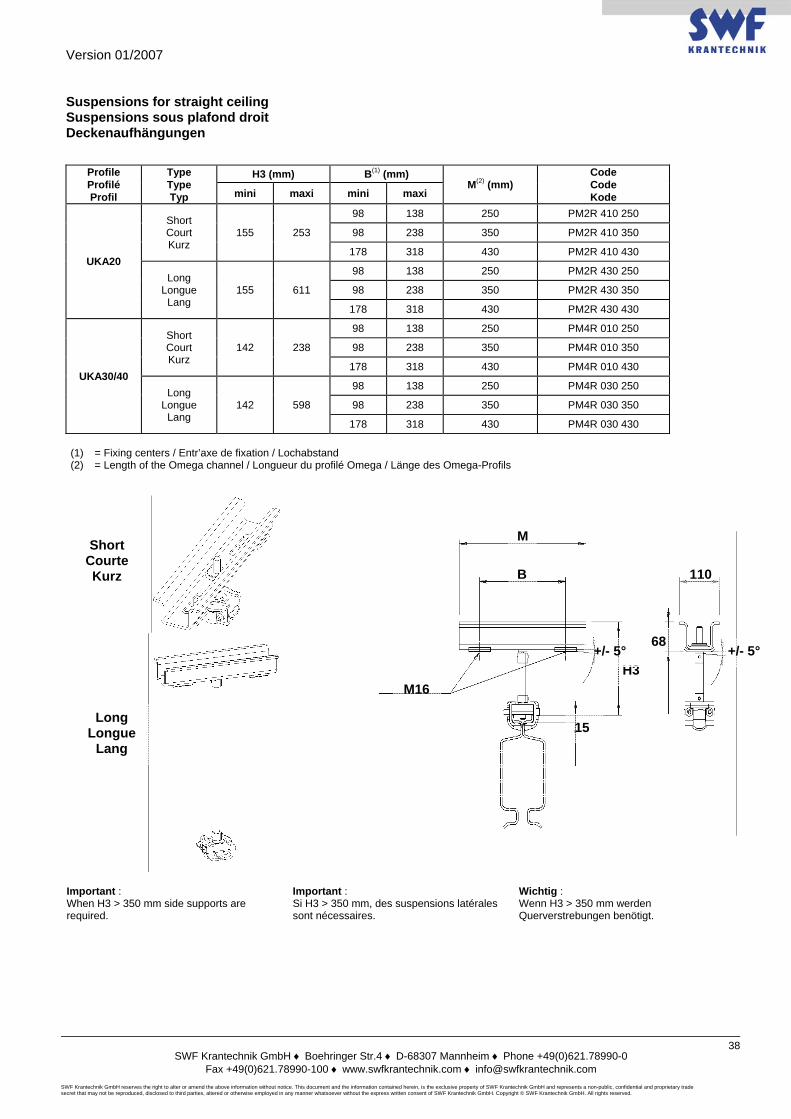
Version 01/2007
SWF Krantechnik GmbH ♦ Boehringer Str.4 ♦ D-68307 Mannheim ♦ Phone +49(0)621.78990-0
Fax +49(0)621.78990-100 ♦ www.swfkrantechnik.com ♦ [email protected] SWF Krantechnik GmbH reserves the right to alter or amend the above information without notice. This document and the information contained herein, is the exclusive property of SWF Krantechnik GmbH and represents a non-public, confidential and proprietary trade secret that may not be reproduced, disclosed to third parties, altered or otherwise employed in any manner whatsoever without the express written consent of SWF Krantechnik GmbH. Copyright © SWF Krantechnik GmbH. All rights reserved.
38
Suspensions for straight ceiling Suspensions sous plafond droit Deckenaufhängungen
Profile Profilé Profil
Type Type Typ
H3 (mm) B(1) (mm) M(2) (mm)
Code Code Kode mini maxi mini maxi
UKA20
Short Court Kurz
155 253
98 138 250 PM2R 410 250
98 238 350 PM2R 410 350
178 318 430 PM2R 410 430
Long Longue Lang
155 611
98 138 250 PM2R 430 250
98 238 350 PM2R 430 350
178 318 430 PM2R 430 430
UKA30/40
Short Court Kurz
142 238
98 138 250 PM4R 010 250
98 238 350 PM4R 010 350
178 318 430 PM4R 010 430
Long Longue Lang
142 598
98 138 250 PM4R 030 250
98 238 350 PM4R 030 350
178 318 430 PM4R 030 430 (1) = Fixing centers / Entr’axe de fixation / Lochabstand (2) = Length of the Omega channel / Longueur du profilé Omega / Länge des Omega-Profils
Important : When H3 > 350 mm side supports are required.
Important : Si H3 > 350 mm, des suspensions latérales sont nécessaires.
Wichtig : Wenn H3 > 350 mm werden Querverstrebungen benötigt.
Short Courte Kurz
Long Longue
Lang
M16
M
B 110
+/- 5°
H3
15
+/- 5° 68
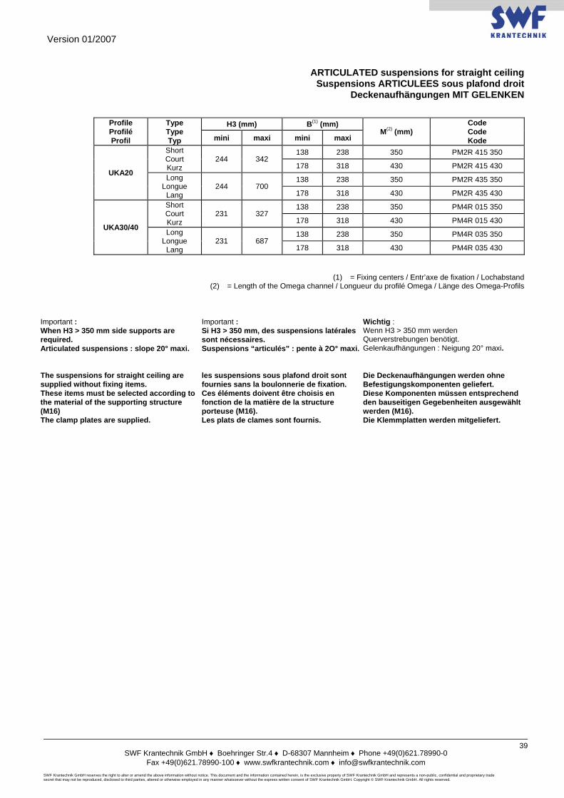
Version 01/2007
SWF Krantechnik GmbH ♦ Boehringer Str.4 ♦ D-68307 Mannheim ♦ Phone +49(0)621.78990-0
Fax +49(0)621.78990-100 ♦ www.swfkrantechnik.com ♦ [email protected] SWF Krantechnik GmbH reserves the right to alter or amend the above information without notice. This document and the information contained herein, is the exclusive property of SWF Krantechnik GmbH and represents a non-public, confidential and proprietary trade secret that may not be reproduced, disclosed to third parties, altered or otherwise employed in any manner whatsoever without the express written consent of SWF Krantechnik GmbH. Copyright © SWF Krantechnik GmbH. All rights reserved.
39
ARTICULATED suspensions for straight ceiling Suspensions ARTICULEES sous plafond droit
Deckenaufhängungen MIT GELENKEN
Profile Profilé Profil
Type Type Typ
H3 (mm) B(1) (mm) M(2) (mm)
Code Code Kode mini maxi mini maxi
UKA20
Short Court Kurz
244 342 138 238 350 PM2R 415 350
178 318 430 PM2R 415 430 Long
Longue Lang
244 700 138 238 350 PM2R 435 350
178 318 430 PM2R 435 430
UKA30/40
Short Court Kurz
231 327 138 238 350 PM4R 015 350
178 318 430 PM4R 015 430 Long
Longue Lang
231 687 138 238 350 PM4R 035 350
178 318 430 PM4R 035 430
(1) = Fixing centers / Entr’axe de fixation / Lochabstand (2) = Length of the Omega channel / Longueur du profilé Omega / Länge des Omega-Profils
Important : When H3 > 350 mm side supports are required. Articulated suspensions : slope 20° maxi.
Important : Si H3 > 350 mm, des suspensions latérales sont nécessaires. Suspensions “articulés” : pente à 2O° maxi.
Wichtig : Wenn H3 > 350 mm werden Querverstrebungen benötigt. Gelenkaufhängungen : Neigung 20° maxi.
The suspensions for straight ceiling are supplied without fixing items. These items must be selected according to the material of the supporting structure (M16) The clamp plates are supplied.
les suspensions sous plafond droit sont fournies sans la boulonnerie de fixation. Ces éléments doivent être choisis en fonction de la matière de la structure porteuse (M16). Les plats de clames sont fournis.
Die Deckenaufhängungen werden ohne Befestigungskomponenten geliefert. Diese Komponenten müssen entsprechend den bauseitigen Gegebenheiten ausgewählt werden (M16). Die Klemmplatten werden mitgeliefert.
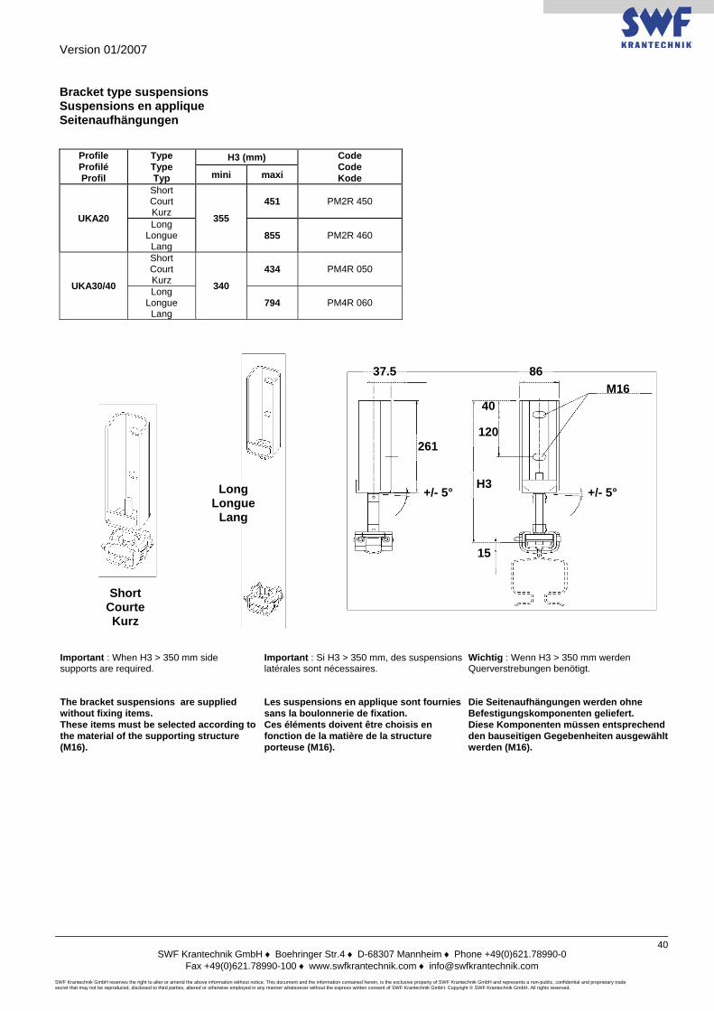
Version 01/2007
SWF Krantechnik GmbH ♦ Boehringer Str.4 ♦ D-68307 Mannheim ♦ Phone +49(0)621.78990-0
Fax +49(0)621.78990-100 ♦ www.swfkrantechnik.com ♦ [email protected] SWF Krantechnik GmbH reserves the right to alter or amend the above information without notice. This document and the information contained herein, is the exclusive property of SWF Krantechnik GmbH and represents a non-public, confidential and proprietary trade secret that may not be reproduced, disclosed to third parties, altered or otherwise employed in any manner whatsoever without the express written consent of SWF Krantechnik GmbH. Copyright © SWF Krantechnik GmbH. All rights reserved.
40
Bracket type suspensions Suspensions en applique Seitenaufhängungen
Profile Profilé Profil
Type Type Typ
H3 (mm) Code Code Kode mini maxi
UKA20
Short Court Kurz 355
451 PM2R 450
Long Longue Lang
855 PM2R 460
UKA30/40
Short Court Kurz 340
434 PM4R 050
Long Longue Lang
794 PM4R 060
Important : When H3 > 350 mm side supports are required.
Important : Si H3 > 350 mm, des suspensions latérales sont nécessaires.
Wichtig : Wenn H3 > 350 mm werden Querverstrebungen benötigt.
The bracket suspensions are supplied without fixing items. These items must be selected according to the material of the supporting structure (M16).
Les suspensions en applique sont fournies sans la boulonnerie de fixation. Ces éléments doivent être choisis en fonction de la matière de la structure porteuse (M16).
Die Seitenaufhängungen werden ohne Befestigungskomponenten geliefert. Diese Komponenten müssen entsprechend den bauseitigen Gegebenheiten ausgewählt werden (M16).
M16 40
120
H3 +/- 5° +/- 5°
261
15
37.5
Short Courte Kurz
Long Longue
Lang
86
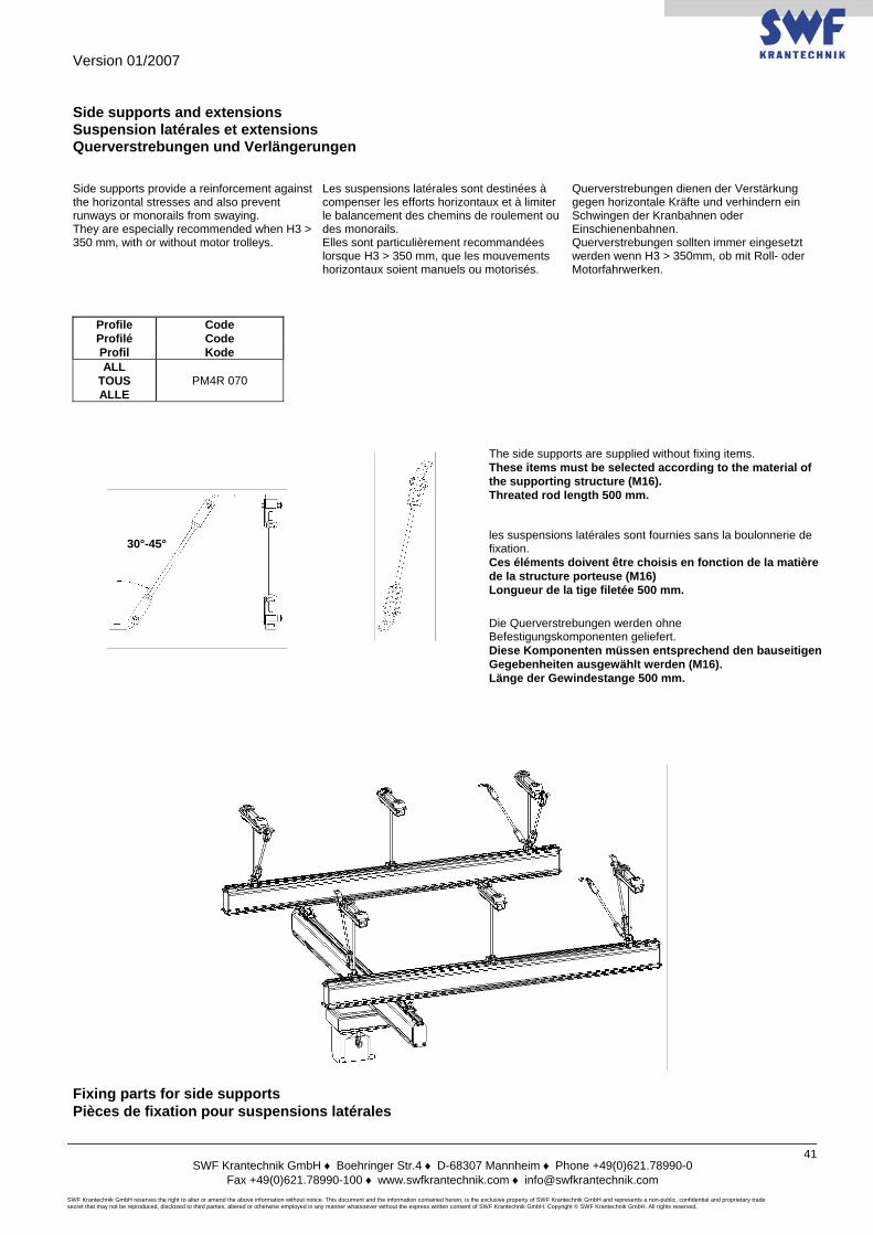
Version 01/2007
SWF Krantechnik GmbH ♦ Boehringer Str.4 ♦ D-68307 Mannheim ♦ Phone +49(0)621.78990-0
Fax +49(0)621.78990-100 ♦ www.swfkrantechnik.com ♦ [email protected] SWF Krantechnik GmbH reserves the right to alter or amend the above information without notice. This document and the information contained herein, is the exclusive property of SWF Krantechnik GmbH and represents a non-public, confidential and proprietary trade secret that may not be reproduced, disclosed to third parties, altered or otherwise employed in any manner whatsoever without the express written consent of SWF Krantechnik GmbH. Copyright © SWF Krantechnik GmbH. All rights reserved.
41
Side supports and extensions Suspension latérales et extensions Querverstrebungen und Verlängerungen Side supports provide a reinforcement against the horizontal stresses and also prevent runways or monorails from swaying. They are especially recommended when H3 > 350 mm, with or without motor trolleys.
Les suspensions latérales sont destinées à compenser les efforts horizontaux et à limiter le balancement des chemins de roulement ou des monorails. Elles sont particulièrement recommandées lorsque H3 > 350 mm, que les mouvements horizontaux soient manuels ou motorisés.
Querverstrebungen dienen der Verstärkung gegen horizontale Kräfte und verhindern ein Schwingen der Kranbahnen oder Einschienenbahnen. Querverstrebungen sollten immer eingesetzt werden wenn H3 > 350mm, ob mit Roll- oder Motorfahrwerken.
Profile Profilé Profil
Code Code Kode
ALL TOUS ALLE
PM4R 070
The side supports are supplied without fixing items. These items must be selected according to the material of the supporting structure (M16). Threated rod length 500 mm.
les suspensions latérales sont fournies sans la boulonnerie de fixation. Ces éléments doivent être choisis en fonction de la matière de la structure porteuse (M16) Longueur de la tige filetée 500 mm. Die Querverstrebungen werden ohne Befestigungskomponenten geliefert. Diese Komponenten müssen entsprechend den bauseitigen Gegebenheiten ausgewählt werden (M16). Länge der Gewindestange 500 mm.
Fixing parts for side supports Pièces de fixation pour suspensions latérales
30°-45°
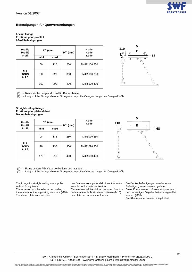
Version 01/2007
SWF Krantechnik GmbH ♦ Boehringer Str.4 ♦ D-68307 Mannheim ♦ Phone +49(0)621.78990-0
Fax +49(0)621.78990-100 ♦ www.swfkrantechnik.com ♦ [email protected] SWF Krantechnik GmbH reserves the right to alter or amend the above information without notice. This document and the information contained herein, is the exclusive property of SWF Krantechnik GmbH and represents a non-public, confidential and proprietary trade secret that may not be reproduced, disclosed to third parties, altered or otherwise employed in any manner whatsoever without the express written consent of SWF Krantechnik GmbH. Copyright © SWF Krantechnik GmbH. All rights reserved.
42
Befestigungen für Querverstrebungen I-beam fixings Fixations pour profilé I I-Profilbefestigungen
Profile Profilé Profil
B(1) (mm) M(2) (mm)
Code Code Kode
mini maxi
ALL TOUS ALLE
80 120 250 PM4R 100 250
80 220 350 PM4R 100 350
160 300 430 PM4R 100 430
(1) = Beam width / Largeur du profilé / Flanschbreite (2) = Length of the Omega channel / Longueur du profilé Omega / Länge des Omega-Profils
Straight ceiling fixings Fixations pour plafond droit Deckenbefestigungen
Profile Profilé Profil
B(1) (mm) M(2) (mm)
Code Code
mini maxi
ALL TOUS ALLE
98 138 250 PM4R 090 250
98 138 350 PM4R 090 350
178 318 430 PM4R 090 430
(1) = Fixing centers / Entr”axe de fixation / Lochabstand (2) = Length of the Omega channel / Longueur du profilé Omega / Länge des Omega-Profils
The fixings for straight ceiling are supplied without fixing items. These items must be selected according to the material of the supporting structure (M16) The clamp plates are supplied.
Les fixations sous plafond droit sont fournies sans la boulonnerie de fixation. Ces éléments doivent être choisis en fonction de la matière de la structure porteuse (M16). Les plats de clames sont fournis.
Die Deckenbefestigungen werden ohne Befestigungskomponenten geliefert. Diese Komponenten müssen entsprechend den bauseitigen Gegebenheiten ausgewählt werden (M16). Die Klemmplatten werden mitgeliefert.
M 110
68
B 68
B 110
M
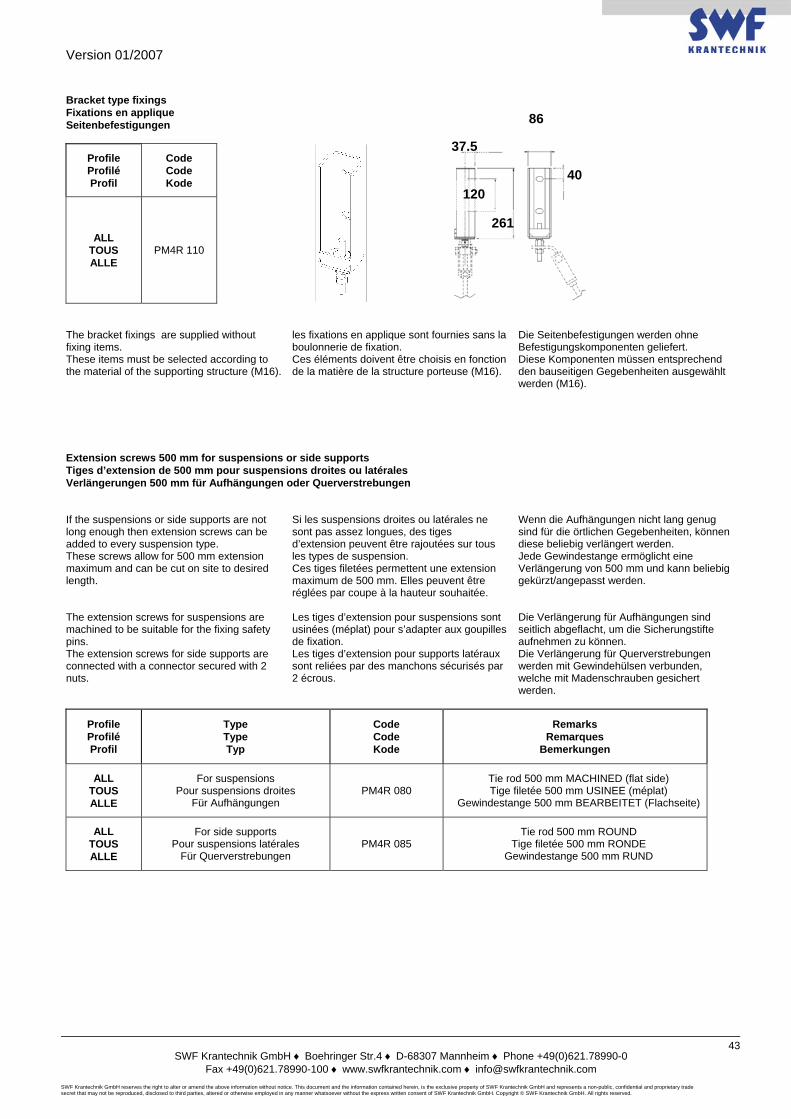
Version 01/2007
SWF Krantechnik GmbH ♦ Boehringer Str.4 ♦ D-68307 Mannheim ♦ Phone +49(0)621.78990-0
Fax +49(0)621.78990-100 ♦ www.swfkrantechnik.com ♦ [email protected] SWF Krantechnik GmbH reserves the right to alter or amend the above information without notice. This document and the information contained herein, is the exclusive property of SWF Krantechnik GmbH and represents a non-public, confidential and proprietary trade secret that may not be reproduced, disclosed to third parties, altered or otherwise employed in any manner whatsoever without the express written consent of SWF Krantechnik GmbH. Copyright © SWF Krantechnik GmbH. All rights reserved.
43
Bracket type fixings Fixations en applique Seitenbefestigungen
Profile Profilé Profil
Code Code Kode
ALL TOUS ALLE
PM4R 110
The bracket fixings are supplied without fixing items. These items must be selected according to the material of the supporting structure (M16).
les fixations en applique sont fournies sans la boulonnerie de fixation. Ces éléments doivent être choisis en fonction de la matière de la structure porteuse (M16).
Die Seitenbefestigungen werden ohne Befestigungskomponenten geliefert. Diese Komponenten müssen entsprechend den bauseitigen Gegebenheiten ausgewählt werden (M16).
Extension screws 500 mm for suspensions or side supports Tiges d’extension de 500 mm pour suspensions droites ou latérales Verlängerungen 500 mm für Aufhängungen oder Querverstrebungen If the suspensions or side supports are not long enough then extension screws can be added to every suspension type. These screws allow for 500 mm extension maximum and can be cut on site to desired length.
Si les suspensions droites ou latérales ne sont pas assez longues, des tiges d’extension peuvent être rajoutées sur tous les types de suspension. Ces tiges filetées permettent une extension maximum de 500 mm. Elles peuvent être réglées par coupe à la hauteur souhaitée.
Wenn die Aufhängungen nicht lang genug sind für die örtlichen Gegebenheiten, können diese beliebig verlängert werden. Jede Gewindestange ermöglicht eine Verlängerung von 500 mm und kann beliebig gekürzt/angepasst werden.
The extension screws for suspensions are machined to be suitable for the fixing safety pins. The extension screws for side supports are connected with a connector secured with 2 nuts.
Les tiges d’extension pour suspensions sont usinées (méplat) pour s’adapter aux goupilles de fixation. Les tiges d’extension pour supports latéraux sont reliées par des manchons sécurisés par 2 écrous.
Die Verlängerung für Aufhängungen sind seitlich abgeflacht, um die Sicherungstifte aufnehmen zu können. Die Verlängerung für Querverstrebungen werden mit Gewindehülsen verbunden, welche mit Madenschrauben gesichert werden.
Profile Profilé Profil
Type Type Typ
Code Code Kode
Remarks Remarques
Bemerkungen
ALL TOUS ALLE
For suspensions Pour suspensions droites
Für Aufhängungen PM4R 080
Tie rod 500 mm MACHINED (flat side) Tige filetée 500 mm USINEE (méplat)
Gewindestange 500 mm BEARBEITET (Flachseite)
ALL TOUS ALLE
For side supports Pour suspensions latérales
Für Querverstrebungen PM4R 085
Tie rod 500 mm ROUND Tige filetée 500 mm RONDE
Gewindestange 500 mm RUND
40
86
37.5
120
261
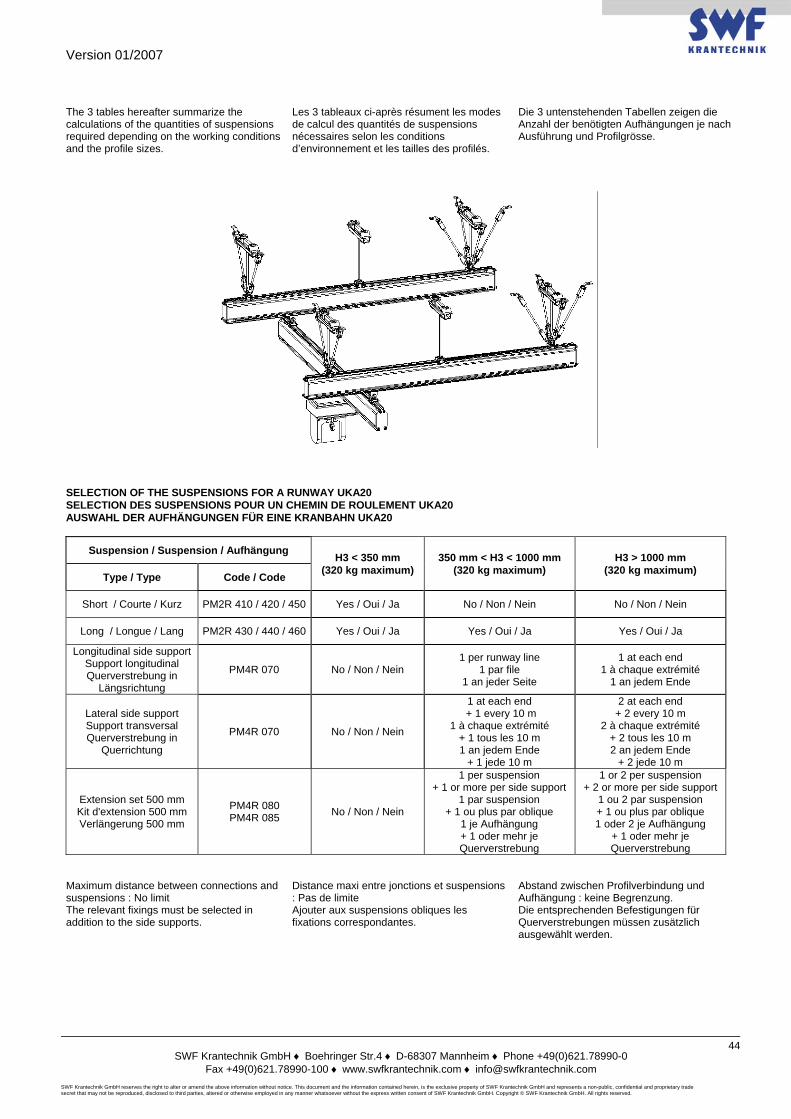
Version 01/2007
SWF Krantechnik GmbH ♦ Boehringer Str.4 ♦ D-68307 Mannheim ♦ Phone +49(0)621.78990-0
Fax +49(0)621.78990-100 ♦ www.swfkrantechnik.com ♦ [email protected] SWF Krantechnik GmbH reserves the right to alter or amend the above information without notice. This document and the information contained herein, is the exclusive property of SWF Krantechnik GmbH and represents a non-public, confidential and proprietary trade secret that may not be reproduced, disclosed to third parties, altered or otherwise employed in any manner whatsoever without the express written consent of SWF Krantechnik GmbH. Copyright © SWF Krantechnik GmbH. All rights reserved.
44
The 3 tables hereafter summarize the calculations of the quantities of suspensions required depending on the working conditions and the profile sizes.
Les 3 tableaux ci-après résument les modes de calcul des quantités de suspensions nécessaires selon les conditions d’environnement et les tailles des profilés.
Die 3 untenstehenden Tabellen zeigen die Anzahl der benötigten Aufhängungen je nach Ausführung und Profilgrösse.
SELECTION OF THE SUSPENSIONS FOR A RUNWAY UKA20 SELECTION DES SUSPENSIONS POUR UN CHEMIN DE ROULEMENT UKA20 AUSWAHL DER AUFHÄNGUNGEN FÜR EINE KRANBAHN UKA20
Suspension / Suspension / Aufhängung H3 < 350 mm (320 kg maximum)
350 mm < H3 < 1000 mm (320 kg maximum)
H3 > 1000 mm (320 kg maximum) Type / Type Code / Code
Short / Courte / Kurz PM2R 410 / 420 / 450 Yes / Oui / Ja No / Non / Nein No / Non / Nein
Long / Longue / Lang PM2R 430 / 440 / 460 Yes / Oui / Ja Yes / Oui / Ja Yes / Oui / Ja
Longitudinal side support Support longitudinal Querverstrebung in
Längsrichtung
PM4R 070 No / Non / Nein 1 per runway line
1 par file 1 an jeder Seite
1 at each end 1 à chaque extrémité
1 an jedem Ende
Lateral side support Support transversal Querverstrebung in
Querrichtung
PM4R 070 No / Non / Nein
1 at each end + 1 every 10 m
1 à chaque extrémité + 1 tous les 10 m 1 an jedem Ende
+ 1 jede 10 m
2 at each end + 2 every 10 m
2 à chaque extrémité + 2 tous les 10 m 2 an jedem Ende
+ 2 jede 10 m
Extension set 500 mm Kit d'extension 500 mm Verlängerung 500 mm
PM4R 080 PM4R 085 No / Non / Nein
1 per suspension + 1 or more per side support
1 par suspension + 1 ou plus par oblique
1 je Aufhängung + 1 oder mehr je Querverstrebung
1 or 2 per suspension + 2 or more per side support
1 ou 2 par suspension + 1 ou plus par oblique 1 oder 2 je Aufhängung
+ 1 oder mehr je Querverstrebung
Maximum distance between connections and suspensions : No limit The relevant fixings must be selected in addition to the side supports.
Distance maxi entre jonctions et suspensions : Pas de limite Ajouter aux suspensions obliques les fixations correspondantes.
Abstand zwischen Profilverbindung und Aufhängung : keine Begrenzung. Die entsprechenden Befestigungen für Querverstrebungen müssen zusätzlich ausgewählt werden.
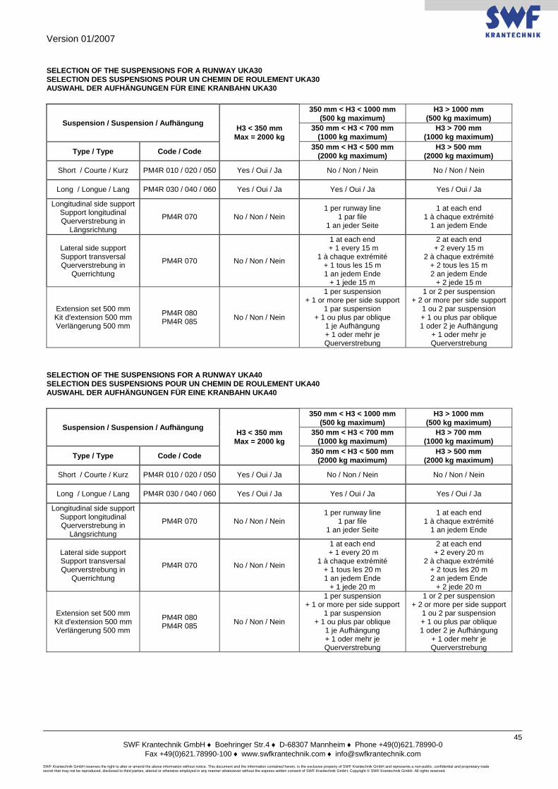
Version 01/2007
SWF Krantechnik GmbH ♦ Boehringer Str.4 ♦ D-68307 Mannheim ♦ Phone +49(0)621.78990-0
Fax +49(0)621.78990-100 ♦ www.swfkrantechnik.com ♦ [email protected] SWF Krantechnik GmbH reserves the right to alter or amend the above information without notice. This document and the information contained herein, is the exclusive property of SWF Krantechnik GmbH and represents a non-public, confidential and proprietary trade secret that may not be reproduced, disclosed to third parties, altered or otherwise employed in any manner whatsoever without the express written consent of SWF Krantechnik GmbH. Copyright © SWF Krantechnik GmbH. All rights reserved.
45
SELECTION OF THE SUSPENSIONS FOR A RUNWAY UKA30 SELECTION DES SUSPENSIONS POUR UN CHEMIN DE ROULEMENT UKA30 AUSWAHL DER AUFHÄNGUNGEN FÜR EINE KRANBAHN UKA30
Suspension / Suspension / Aufhängung H3 < 350 mm Max = 2000 kg
350 mm < H3 < 1000 mm (500 kg maximum)
H3 > 1000 mm (500 kg maximum)
350 mm < H3 < 700 mm (1000 kg maximum)
H3 > 700 mm (1000 kg maximum)
Type / Type Code / Code 350 mm < H3 < 500 mm (2000 kg maximum)
H3 > 500 mm (2000 kg maximum)
Short / Courte / Kurz PM4R 010 / 020 / 050 Yes / Oui / Ja No / Non / Nein No / Non / Nein
Long / Longue / Lang PM4R 030 / 040 / 060 Yes / Oui / Ja Yes / Oui / Ja Yes / Oui / Ja
Longitudinal side support Support longitudinal Querverstrebung in
Längsrichtung
PM4R 070 No / Non / Nein 1 per runway line
1 par file 1 an jeder Seite
1 at each end 1 à chaque extrémité
1 an jedem Ende
Lateral side support Support transversal Querverstrebung in
Querrichtung
PM4R 070 No / Non / Nein
1 at each end + 1 every 15 m
1 à chaque extrémité + 1 tous les 15 m 1 an jedem Ende
+ 1 jede 15 m
2 at each end + 2 every 15 m
2 à chaque extrémité + 2 tous les 15 m 2 an jedem Ende
+ 2 jede 15 m
Extension set 500 mm Kit d'extension 500 mm Verlängerung 500 mm
PM4R 080 PM4R 085 No / Non / Nein
1 per suspension + 1 or more per side support
1 par suspension + 1 ou plus par oblique
1 je Aufhängung + 1 oder mehr je Querverstrebung
1 or 2 per suspension + 2 or more per side support
1 ou 2 par suspension + 1 ou plus par oblique 1 oder 2 je Aufhängung
+ 1 oder mehr je Querverstrebung
SELECTION OF THE SUSPENSIONS FOR A RUNWAY UKA40 SELECTION DES SUSPENSIONS POUR UN CHEMIN DE ROULEMENT UKA40 AUSWAHL DER AUFHÄNGUNGEN FÜR EINE KRANBAHN UKA40
Suspension / Suspension / Aufhängung H3 < 350 mm Max = 2000 kg
350 mm < H3 < 1000 mm (500 kg maximum)
H3 > 1000 mm (500 kg maximum)
350 mm < H3 < 700 mm (1000 kg maximum)
H3 > 700 mm (1000 kg maximum)
Type / Type Code / Code 350 mm < H3 < 500 mm (2000 kg maximum)
H3 > 500 mm (2000 kg maximum)
Short / Courte / Kurz PM4R 010 / 020 / 050 Yes / Oui / Ja No / Non / Nein No / Non / Nein
Long / Longue / Lang PM4R 030 / 040 / 060 Yes / Oui / Ja Yes / Oui / Ja Yes / Oui / Ja
Longitudinal side support Support longitudinal Querverstrebung in
Längsrichtung
PM4R 070 No / Non / Nein 1 per runway line
1 par file 1 an jeder Seite
1 at each end 1 à chaque extrémité
1 an jedem Ende
Lateral side support Support transversal Querverstrebung in
Querrichtung
PM4R 070 No / Non / Nein
1 at each end + 1 every 20 m
1 à chaque extrémité + 1 tous les 20 m 1 an jedem Ende
+ 1 jede 20 m
2 at each end + 2 every 20 m
2 à chaque extrémité + 2 tous les 20 m 2 an jedem Ende
+ 2 jede 20 m
Extension set 500 mm Kit d'extension 500 mm Verlängerung 500 mm
PM4R 080 PM4R 085 No / Non / Nein
1 per suspension + 1 or more per side support
1 par suspension + 1 ou plus par oblique
1 je Aufhängung + 1 oder mehr je Querverstrebung
1 or 2 per suspension + 2 or more per side support
1 ou 2 par suspension + 1 ou plus par oblique 1 oder 2 je Aufhängung
+ 1 oder mehr je Querverstrebung
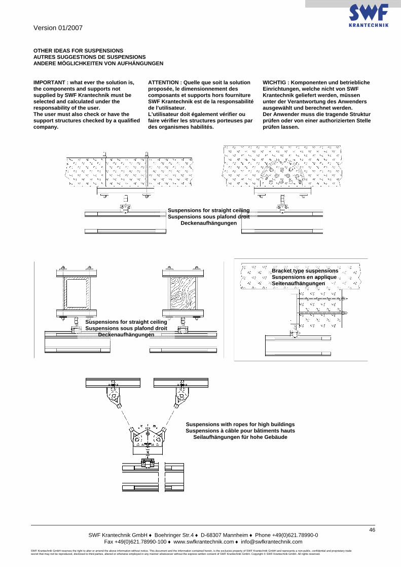
Version 01/2007
SWF Krantechnik GmbH ♦ Boehringer Str.4 ♦ D-68307 Mannheim ♦ Phone +49(0)621.78990-0
Fax +49(0)621.78990-100 ♦ www.swfkrantechnik.com ♦ [email protected] SWF Krantechnik GmbH reserves the right to alter or amend the above information without notice. This document and the information contained herein, is the exclusive property of SWF Krantechnik GmbH and represents a non-public, confidential and proprietary trade secret that may not be reproduced, disclosed to third parties, altered or otherwise employed in any manner whatsoever without the express written consent of SWF Krantechnik GmbH. Copyright © SWF Krantechnik GmbH. All rights reserved.
46
OTHER IDEAS FOR SUSPENSIONS AUTRES SUGGESTIONS DE SUSPENSIONS ANDERE MÖGLICHKEITEN VON AUFHÄNGUNGEN IMPORTANT : what ever the solution is, the components and supports not supplied by SWF Krantechnik must be selected and calculated under the responsability of the user. The user must also check or have the support structures checked by a qualified company.
ATTENTION : Quelle que soit la solution proposée, le dimensionnement des composants et supports hors fourniture SWF Krantechnik est de la responsabilité de l’utilisateur. L’utilisateur doit également vérifier ou faire vérifier les structures porteuses par des organismes habilités.
WICHTIG : Komponenten und betriebliche Einrichtungen, welche nicht von SWF Krantechnik geliefert werden, müssen unter der Verantwortung des Anwenders ausgewählt und berechnet werden. Der Anwender muss die tragende Struktur prüfen oder von einer authorizierten Stelle prüfen lassen.
Suspensions for straight ceiling Suspensions sous plafond droit
Deckenaufhängungen
Suspensions for straight ceiling Suspensions sous plafond droit
Deckenaufhängungen
Bracket type suspensions Suspensions en applique Seitenaufhängungen
Suspensions with ropes for high buildings Suspensions à câble pour bâtiments hauts
Seilaufhängungen für hohe Gebäude
Version 01/2007
SWF Krantechnik GmbH ♦ Boehringer Str.4 ♦ D-68307 Mannheim ♦ Phone +49(0)621.78990-0
Fax +49(0)621.78990-100 ♦ www.swfkrantechnik.com ♦ [email protected] SWF Krantechnik GmbH reserves the right to alter or amend the above information without notice. This document and the information contained herein, is the exclusive property of SWF Krantechnik GmbH and represents a non-public, confidential and proprietary trade secret that may not be reproduced, disclosed to third parties, altered or otherwise employed in any manner whatsoever without the express written consent of SWF Krantechnik GmbH. Copyright © SWF Krantechnik GmbH. All rights reserved.
47
PUSH TROLLEYS CHARIOTS MANUELS SCHIEBEFAHRWERKE The reduced size of the trolley wheels ensure a smooth and silent running inside the profiles. The nylon wheels are fitted with ball bearings and fixed with circlips. The trolley frame is galvanized.
Par sa faible largeur, la bande de roulement des chariots assure un déplacement souple et silencieux dans les profilés. Les galets nylon sont montés sur roulements à billes et maintenus par circlips. Le corps des chariots est galvanisé.
Die schmalen Räder der Fahrwerke erlauben eine leichte und leise Fahrbewegung der Last. Die Nylonräder sind auf Kugellagern montiert. Die Fahrwerke sind zum besseren Korrosionsschutz galvanisiert.
The trolleys for UKA20 are self-guided inside the profile thanks to its own design.
Les chariots pour profilés UKA20 sont auto-guidés dans le profilé de part la conception de celui-ci.
Die Fahrwerke für UKA20 sind selbstzentrierend ausgeführt.
The trolleys for UKA30 and UKA40 profiles are fitted with integrated guide rollers that ensure a perfect centering in the profiles and enable the running in curves without any particular design (simple trolleys up to 1000 kg). Above 1000 kg, the trolleys are doubled rigid (for straight profiles) or doubled articulated (for curves or switches).
Les chariots pour profilés UKA30 et UKA40 sont équipés de roulements guides intégrés assurant un centrage parfait de ceux-ci à l’intérieur des profilés et permettant le passage dans des courbes, sans construction particulière (chariots simples jusque 1000 kg).Au-delà de 1000 kg, les chariots sont doubles rigides (profilés droits) ou doubles articulés (courbes, aiguillages).
Die Fahrwerke für UKA30 und UKA40 sind mit horizontalen Lagern ausgestattet, die eine perfekte horizontale Führung gewährleisten, sowohl in geraden Bahnen als auch in Kurven (Fahrwerke bis 1000 kg). Über 1000 kg verwenden wir Doppel-Fahrwerke (für gerade Bahnen) oder Doppel-Gelenk-Fahrwerke (für Kurven, Weichen).
The articulated girder trolleys are all fitted with a coupling mounted on thrust bearing and secured with a Norlock nut. This unic construction enables for an exceptional ergonomy (smooth handling) and working life.
Les chariots porte-poutre articulés sont tous équipés d’une butée à billes sécurisée par un écrou Norlock. Cette construction unique autorise une ergonomie (souplesse d’utilisation) et une durée de vie exceptionnelles.
Die standard Gelenkfahrwerke sind mit einem Rollenlager ausgerüstet und durch Keilsicherungsscheiben gegen aufdrehen gesichert. Diese einzigartige Konstruktion ermöglicht eine aussergewöhnliche Ergonomy (leichtes Handhaben) und eine längere Lebensdauer.
Thanks to the modular construction of the PM it is possible to fit motor trolleys to an existing installation later on.
La modularité du PM permet de motoriser ultérieurement une installation existante avec des chariots manuels.
Dank der Modulbauweise können manuelle Fahrwerke nachträglich mit Elektrofahrwerken kombiniert werden.
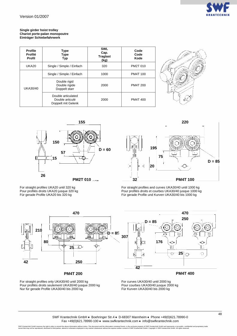
Version 01/2007
SWF Krantechnik GmbH ♦ Boehringer Str.4 ♦ D-68307 Mannheim ♦ Phone +49(0)621.78990-0
Fax +49(0)621.78990-100 ♦ www.swfkrantechnik.com ♦ [email protected] SWF Krantechnik GmbH reserves the right to alter or amend the above information without notice. This document and the information contained herein, is the exclusive property of SWF Krantechnik GmbH and represents a non-public, confidential and proprietary trade secret that may not be reproduced, disclosed to third parties, altered or otherwise employed in any manner whatsoever without the express written consent of SWF Krantechnik GmbH. Copyright © SWF Krantechnik GmbH. All rights reserved.
48
Single girder hoist trolley Chariot porte-palan monopoutre Einträger Schiebefahrwerk
Profile Profilé Profil
Type Type Typ
SWL Cap.
Traglast (kg)
Code Code Kode
UKA20 Single / Simple / Einfach 320 PM2T 010
UKA30/40
Single / Simple / Einfach 1000 PM4T 100
Double rigid Double rigide Doppelt starr
2000 PM4T 200
Double articulated Double articulé
Doppelt mit Gelenk 2000 PM4T 400
For straight profiles UKA20 until 320 kg Pour profilés droits UKA20 jusque 320 kg Für gerade Profile UKA20 bis 320 kg
For straight profiles and curves UKA30/40 until 1000 kg Pour profilés droits et courbes UKA30/40 jusque 1000 kg Für gerade Profile und Kurven UKA30/40 bis 1000 kg
For straight profiles only UKA30/40 until 2000 kg Pour profilés droits seulement UKA30/40 jusque 2000 kg Nur für gerade Profile UKA30/40 bis 2000 kg
For curves UKA30/40 until 2000 kg Pour courbes UKA30/40 jusque 2000 kg Für Kurven UKA30/40 bis 2000 kg
155
D = 60
150
57
26
15
20 D = 85
220
195
75
32 PM2T 010 PM4T 100
PM4T 400 PM4T 200
470 470
D = 85
D = 85 250
25
307 176
210
250
25
42 42
80
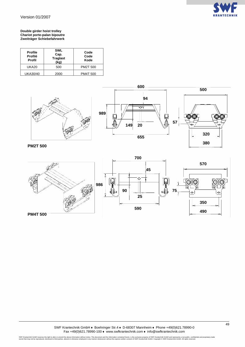
Version 01/2007
SWF Krantechnik GmbH ♦ Boehringer Str.4 ♦ D-68307 Mannheim ♦ Phone +49(0)621.78990-0
Fax +49(0)621.78990-100 ♦ www.swfkrantechnik.com ♦ [email protected] SWF Krantechnik GmbH reserves the right to alter or amend the above information without notice. This document and the information contained herein, is the exclusive property of SWF Krantechnik GmbH and represents a non-public, confidential and proprietary trade secret that may not be reproduced, disclosed to third parties, altered or otherwise employed in any manner whatsoever without the express written consent of SWF Krantechnik GmbH. Copyright © SWF Krantechnik GmbH. All rights reserved.
49
Double girder hoist trolley Chariot porte-palan bipoutre Zweiträger Schiebefahrwerk
Profile Profilé Profil
SWL Cap.
Traglast (kg)
Code Code Kode
UKA20 500 PM2T 500
UKA30/40 2000 PM4T 500
600 500
320
380 655
94
989
149 57
700 570
350
490 590
986 90
20
25 75
PM2T 500
PM4T 500
45
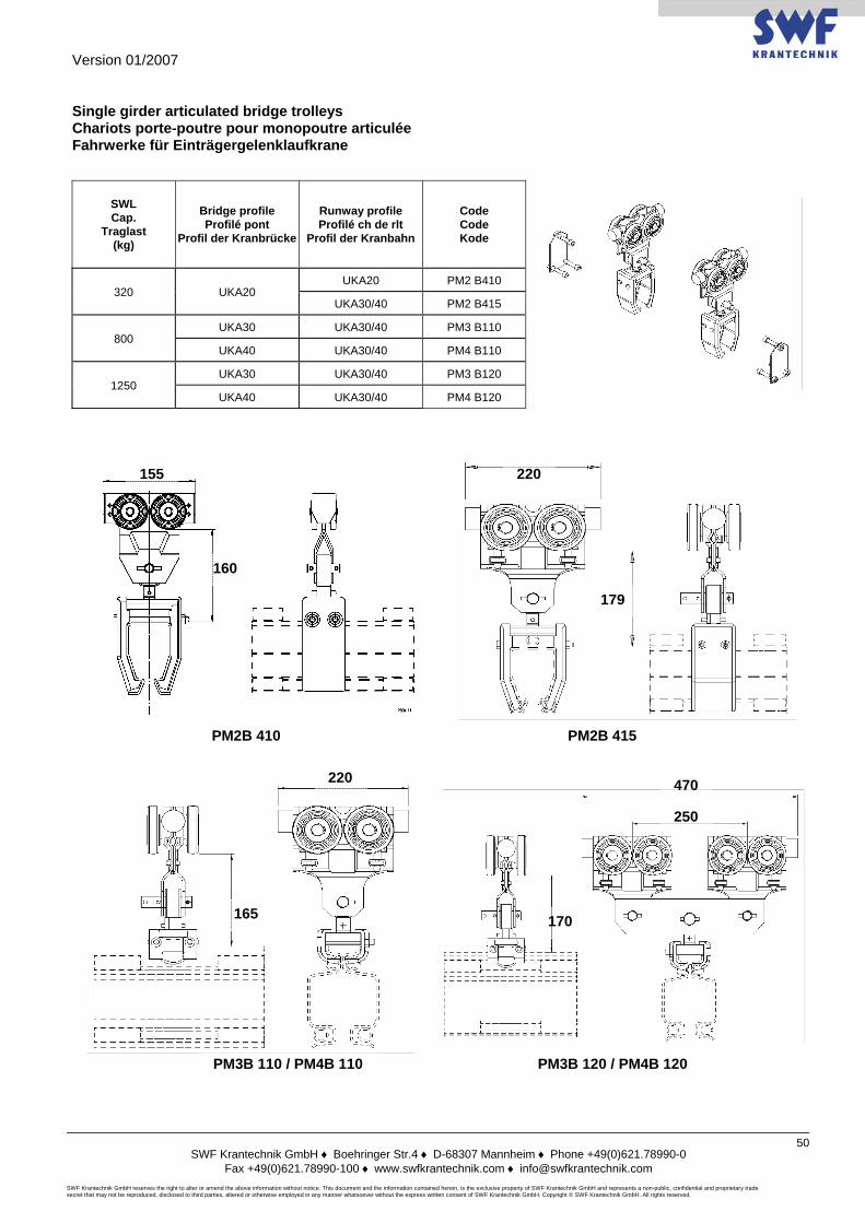
Version 01/2007
SWF Krantechnik GmbH ♦ Boehringer Str.4 ♦ D-68307 Mannheim ♦ Phone +49(0)621.78990-0
Fax +49(0)621.78990-100 ♦ www.swfkrantechnik.com ♦ [email protected] SWF Krantechnik GmbH reserves the right to alter or amend the above information without notice. This document and the information contained herein, is the exclusive property of SWF Krantechnik GmbH and represents a non-public, confidential and proprietary trade secret that may not be reproduced, disclosed to third parties, altered or otherwise employed in any manner whatsoever without the express written consent of SWF Krantechnik GmbH. Copyright © SWF Krantechnik GmbH. All rights reserved.
50
Single girder articulated bridge trolleys Chariots porte-poutre pour monopoutre articulée Fahrwerke für Einträgergelenklaufkrane
SWL Cap.
Traglast (kg)
Bridge profile Profilé pont
Profil der Kranbrücke
Runway profile Profilé ch de rlt
Profil der Kranbahn
Code Code Kode
320 UKA20 UKA20 PM2 B410
UKA30/40 PM2 B415
800 UKA30 UKA30/40 PM3 B110
UKA40 UKA30/40 PM4 B110
1250 UKA30 UKA30/40 PM3 B120
UKA40 UKA30/40 PM4 B120
220
179
220
165
250
470
170
PM2B 410 PM2B 415
PM3B 110 / PM4B 110 PM3B 120 / PM4B 120
155
160
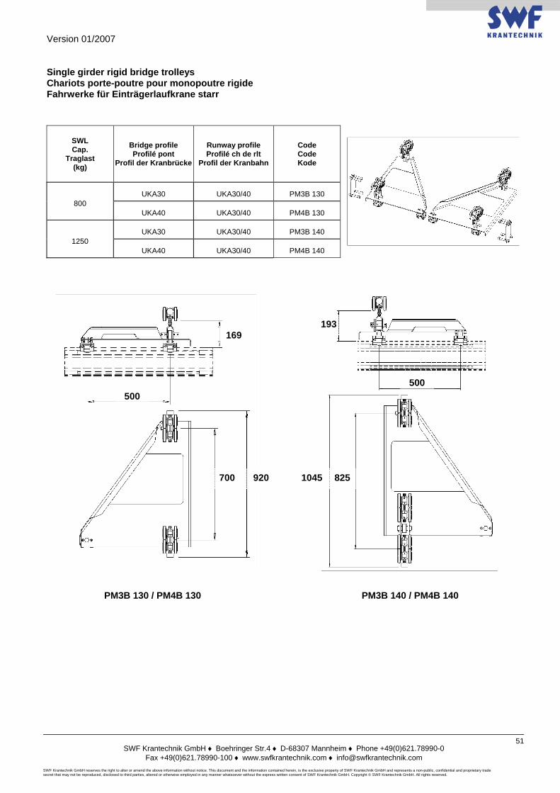
Version 01/2007
SWF Krantechnik GmbH ♦ Boehringer Str.4 ♦ D-68307 Mannheim ♦ Phone +49(0)621.78990-0
Fax +49(0)621.78990-100 ♦ www.swfkrantechnik.com ♦ [email protected] SWF Krantechnik GmbH reserves the right to alter or amend the above information without notice. This document and the information contained herein, is the exclusive property of SWF Krantechnik GmbH and represents a non-public, confidential and proprietary trade secret that may not be reproduced, disclosed to third parties, altered or otherwise employed in any manner whatsoever without the express written consent of SWF Krantechnik GmbH. Copyright © SWF Krantechnik GmbH. All rights reserved.
51
Single girder rigid bridge trolleys Chariots porte-poutre pour monopoutre rigide Fahrwerke für Einträgerlaufkrane starr
SWL Cap.
Traglast (kg)
Bridge profile Profilé pont
Profil der Kranbrücke
Runway profile Profilé ch de rlt
Profil der Kranbahn
Code Code Kode
800 UKA30 UKA30/40 PM3B 130
UKA40 UKA30/40 PM4B 130
1250 UKA30 UKA30/40 PM3B 140
UKA40 UKA30/40 PM4B 140
169
500
700 920
500
825 1045
193
PM3B 130 / PM4B 130 PM3B 140 / PM4B 140
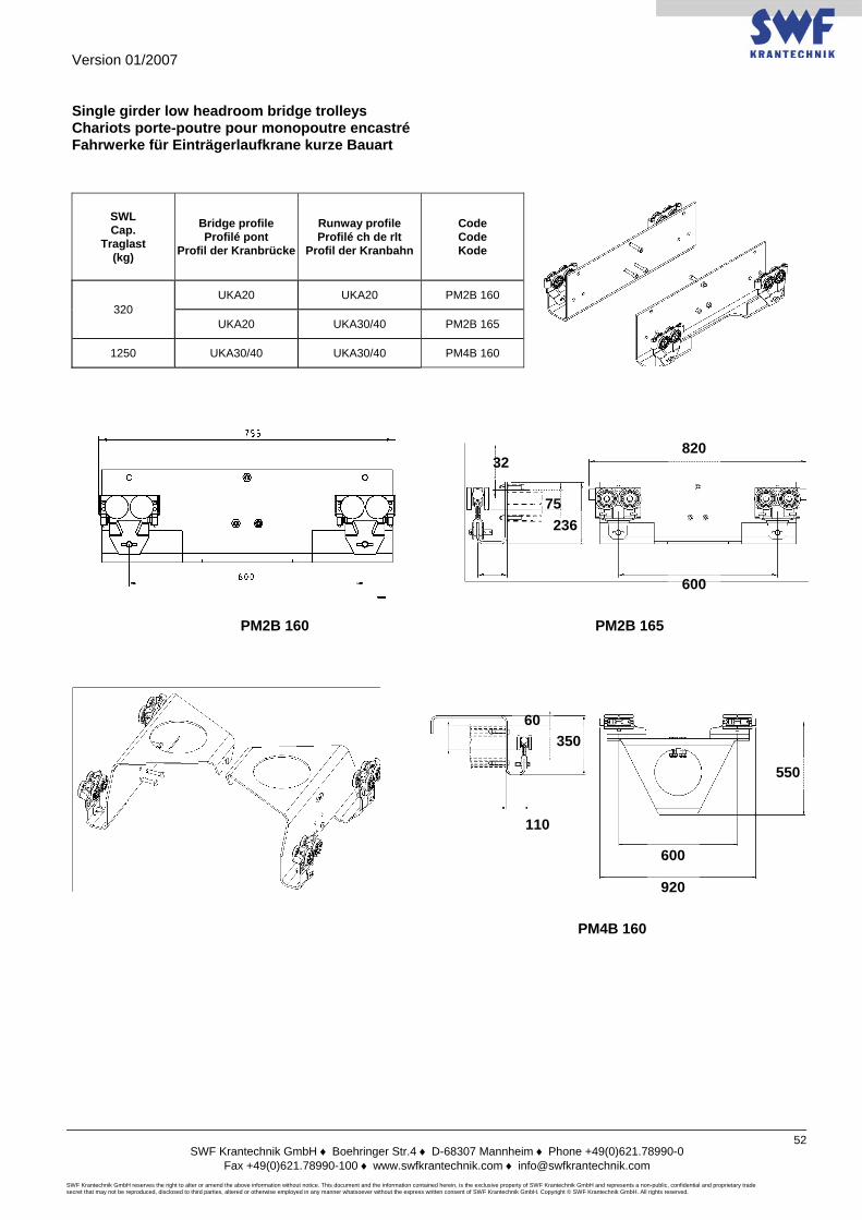
Version 01/2007
SWF Krantechnik GmbH ♦ Boehringer Str.4 ♦ D-68307 Mannheim ♦ Phone +49(0)621.78990-0
Fax +49(0)621.78990-100 ♦ www.swfkrantechnik.com ♦ [email protected] SWF Krantechnik GmbH reserves the right to alter or amend the above information without notice. This document and the information contained herein, is the exclusive property of SWF Krantechnik GmbH and represents a non-public, confidential and proprietary trade secret that may not be reproduced, disclosed to third parties, altered or otherwise employed in any manner whatsoever without the express written consent of SWF Krantechnik GmbH. Copyright © SWF Krantechnik GmbH. All rights reserved.
52
Single girder low headroom bridge trolleys Chariots porte-poutre pour monopoutre encastré Fahrwerke für Einträgerlaufkrane kurze Bauart
SWL Cap.
Traglast (kg)
Bridge profile Profilé pont
Profil der Kranbrücke
Runway profile Profilé ch de rlt
Profil der Kranbahn
Code Code Kode
320 UKA20 UKA20 PM2B 160
UKA20 UKA30/40 PM2B 165
1250 UKA30/40 UKA30/40 PM4B 160
75
32
236
PM2B 160 PM2B 165
820
600
PM4B 160
600
920
550
350
110
60
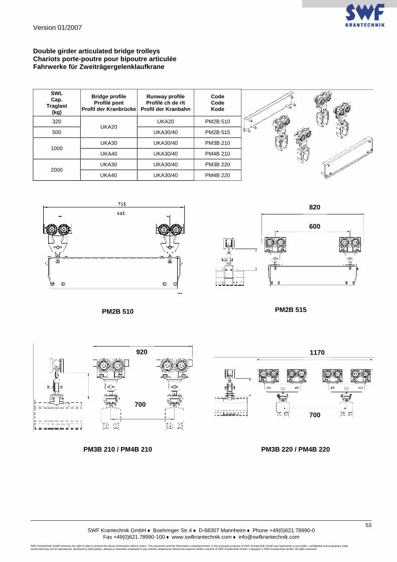
Version 01/2007
SWF Krantechnik GmbH ♦ Boehringer Str.4 ♦ D-68307 Mannheim ♦ Phone +49(0)621.78990-0
Fax +49(0)621.78990-100 ♦ www.swfkrantechnik.com ♦ [email protected] SWF Krantechnik GmbH reserves the right to alter or amend the above information without notice. This document and the information contained herein, is the exclusive property of SWF Krantechnik GmbH and represents a non-public, confidential and proprietary trade secret that may not be reproduced, disclosed to third parties, altered or otherwise employed in any manner whatsoever without the express written consent of SWF Krantechnik GmbH. Copyright © SWF Krantechnik GmbH. All rights reserved.
53
Double girder articulated bridge trolleys Chariots porte-poutre pour bipoutre articulée Fahrwerke für Zweiträgergelenklaufkrane
SWL Cap.
Traglast (kg)
Bridge profile Profilé pont
Profil der Kranbrücke
Runway profile Profilé ch de rlt
Profil der Kranbahn
Code Code Kode
320 UKA20
UKA20 PM2B 510
500 UKA30/40 PM2B 515
1000 UKA30 UKA30/40 PM3B 210
UKA40 UKA30/40 PM4B 210
2000 UKA30 UKA30/40 PM3B 220
UKA40 UKA30/40 PM4B 220
820
600
1170
700 700
920
PM2B 510 PM2B 515
PM3B 220 / PM4B 220 PM3B 210 / PM4B 210
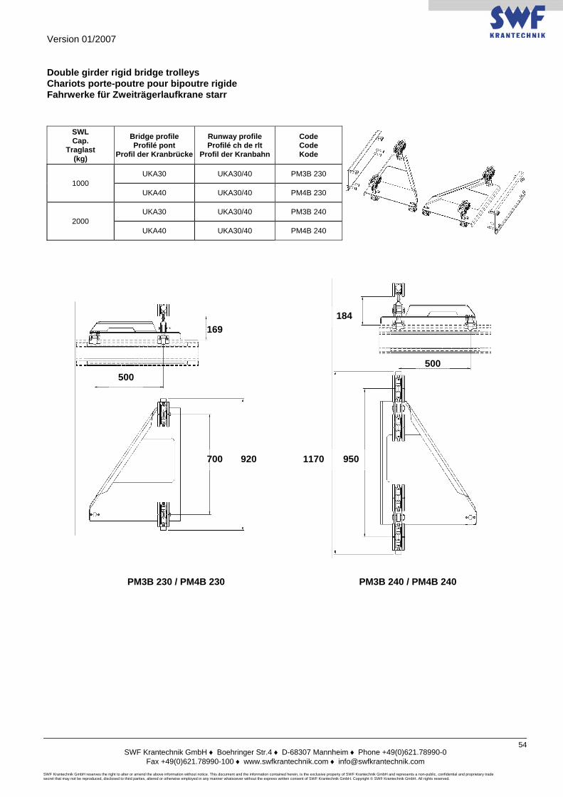
Version 01/2007
SWF Krantechnik GmbH ♦ Boehringer Str.4 ♦ D-68307 Mannheim ♦ Phone +49(0)621.78990-0
Fax +49(0)621.78990-100 ♦ www.swfkrantechnik.com ♦ [email protected] SWF Krantechnik GmbH reserves the right to alter or amend the above information without notice. This document and the information contained herein, is the exclusive property of SWF Krantechnik GmbH and represents a non-public, confidential and proprietary trade secret that may not be reproduced, disclosed to third parties, altered or otherwise employed in any manner whatsoever without the express written consent of SWF Krantechnik GmbH. Copyright © SWF Krantechnik GmbH. All rights reserved.
54
Double girder rigid bridge trolleys Chariots porte-poutre pour bipoutre rigide Fahrwerke für Zweiträgerlaufkrane starr
SWL Cap.
Traglast (kg)
Bridge profile Profilé pont
Profil der Kranbrücke
Runway profile Profilé ch de rlt
Profil der Kranbahn
Code Code Kode
1000 UKA30 UKA30/40 PM3B 230
UKA40 UKA30/40 PM4B 230
2000 UKA30 UKA30/40 PM3B 240
UKA40 UKA30/40 PM4B 240
920 700
169
500 500
184
950 1170
PM3B 230 / PM4B 230 PM3B 240 / PM4B 240
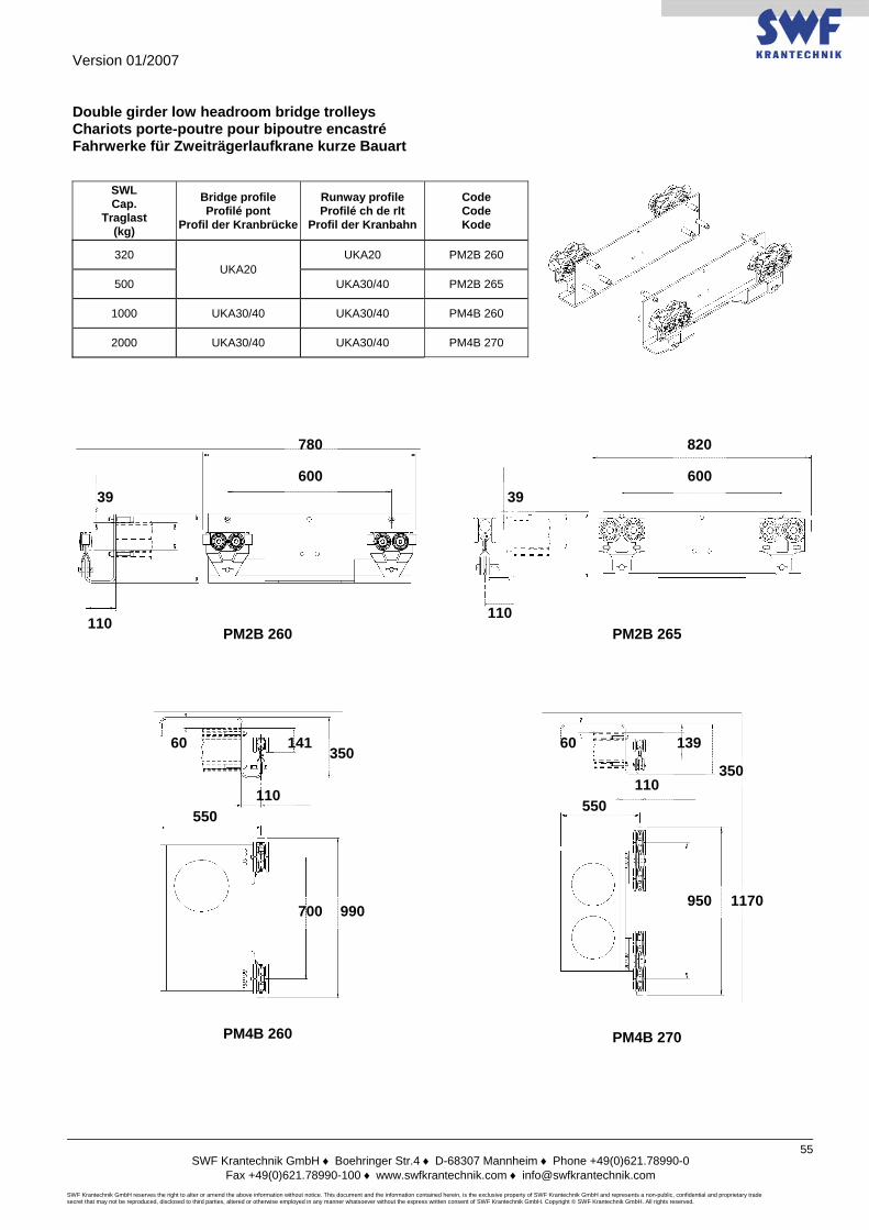
Version 01/2007
SWF Krantechnik GmbH ♦ Boehringer Str.4 ♦ D-68307 Mannheim ♦ Phone +49(0)621.78990-0
Fax +49(0)621.78990-100 ♦ www.swfkrantechnik.com ♦ [email protected] SWF Krantechnik GmbH reserves the right to alter or amend the above information without notice. This document and the information contained herein, is the exclusive property of SWF Krantechnik GmbH and represents a non-public, confidential and proprietary trade secret that may not be reproduced, disclosed to third parties, altered or otherwise employed in any manner whatsoever without the express written consent of SWF Krantechnik GmbH. Copyright © SWF Krantechnik GmbH. All rights reserved.
55
Double girder low headroom bridge trolleys Chariots porte-poutre pour bipoutre encastré Fahrwerke für Zweiträgerlaufkrane kurze Bauart
SWL Cap.
Traglast (kg)
Bridge profile Profilé pont
Profil der Kranbrücke
Runway profile Profilé ch de rlt
Profil der Kranbahn
Code Code Kode
320 UKA20
UKA20 PM2B 260
500 UKA30/40 PM2B 265
1000 UKA30/40 UKA30/40 PM4B 260
2000 UKA30/40 UKA30/40 PM4B 270
780
600
110
39 39
110
600
820
1170
350
139 60
550
950
110 110
350 141 60
550
700 990
PM2B 260 PM2B 265
PM4B 270 PM4B 260
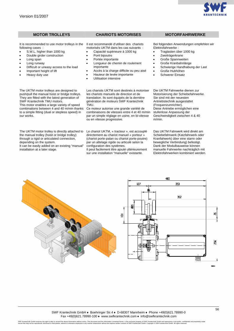
Version 01/2007
SWF Krantechnik GmbH ♦ Boehringer Str.4 ♦ D-68307 Mannheim ♦ Phone +49(0)621.78990-0
Fax +49(0)621.78990-100 ♦ www.swfkrantechnik.com ♦ [email protected] SWF Krantechnik GmbH reserves the right to alter or amend the above information without notice. This document and the information contained herein, is the exclusive property of SWF Krantechnik GmbH and represents a non-public, confidential and proprietary trade secret that may not be reproduced, disclosed to third parties, altered or otherwise employed in any manner whatsoever without the express written consent of SWF Krantechnik GmbH. Copyright © SWF Krantechnik GmbH. All rights reserved.
56
MOTOR TROLLEYS CHARIOTS MOTORISES MOTORFAHRWERKE It is recommended to use motor trolleys in the following cases : • S.W.L. higher than 1000 kg • Double girder construction • Long span • Long runway • Difficult or uneasy access to the load • Important height of lift • Heavy duty use
Il est recommandé d’utiliser des chariots motorisés UKTM dans les cas suivants : • Capacité supérieure à 1000 kg • Pont bipoutre • Portée importante • Longueur de chemin de roulement
importante • Accès à la charge difficile ou peu aisé • Hauteur de levée importante • Utilisation intensive
Bei folgenden Anwendungen empfehlen wir Elektrofahrwerke : • Traglasten über 1000 kg • Zweiträgerkrane • Große Spannweiten • Große Kranbahnlänge • Schwierige Handhabung der Last • Große Hubhöhen • Schwerer Einsatz
The UKTM motor trolleys are designed to push/pull the manual hoist or bridge trolleys. They are fitted with the latest generation of SWF Krantechnik TMU motors. This motor enables a large variety of speed combinations between 4 and 40 m/min thanks to a simple fitting (dual or stepless speed) in our works.
Les chariots UKTM sont destinés à motoriser les chariots manuels de direction et de translation. Ils sont équipés de la dernière génération de moteurs SWF Krantechnik TMU. Ce moteur autorise une grande variété de combinaisons de vitesses entre 4 et 40 m/min par un simple réglage en usine, en bi-vitesse ou en vitesse progressive.
Die UKTM Fahrwerke dienen zur Motorisierung der Schiebefahrwerke. Sie sind mit der neuesten Antriebstechnik ausgestattet (Frequenzumrichter). Diese Antriebe ermöglichen eine stufenlose Anpassung der Geschwindigkeit zwischen 4 & 40 m/min.
The UKTM motor trolley is directly attached to the manual trolley (hoist or bridge trolley) through a rigid or articulated connection, depending on the system. It can be easily added on an existing “manual” installation at a later stage.
Le chariot UKTM, « tracteur », est accouplé directement au chariot manuel « porteur » (chariot porte-palan ou chariot porte-poutre) par un attelage rigide ou articulé selon la configuration des systèmes. Il peut facilement être ajouté ultérieurement sur une installation “manuelle” existante.
Das UKTM Fahrwerk wird direkt am Schiebefahrwerk (Katzfahrwerk oder Kranfahwerk) über eine starre oder bewegliche Verbindung) befestigt. Dank der Modulbauweise können manuelle Fahrwerke nachträglich mit Elektrofahrwerken kombiniert werden.
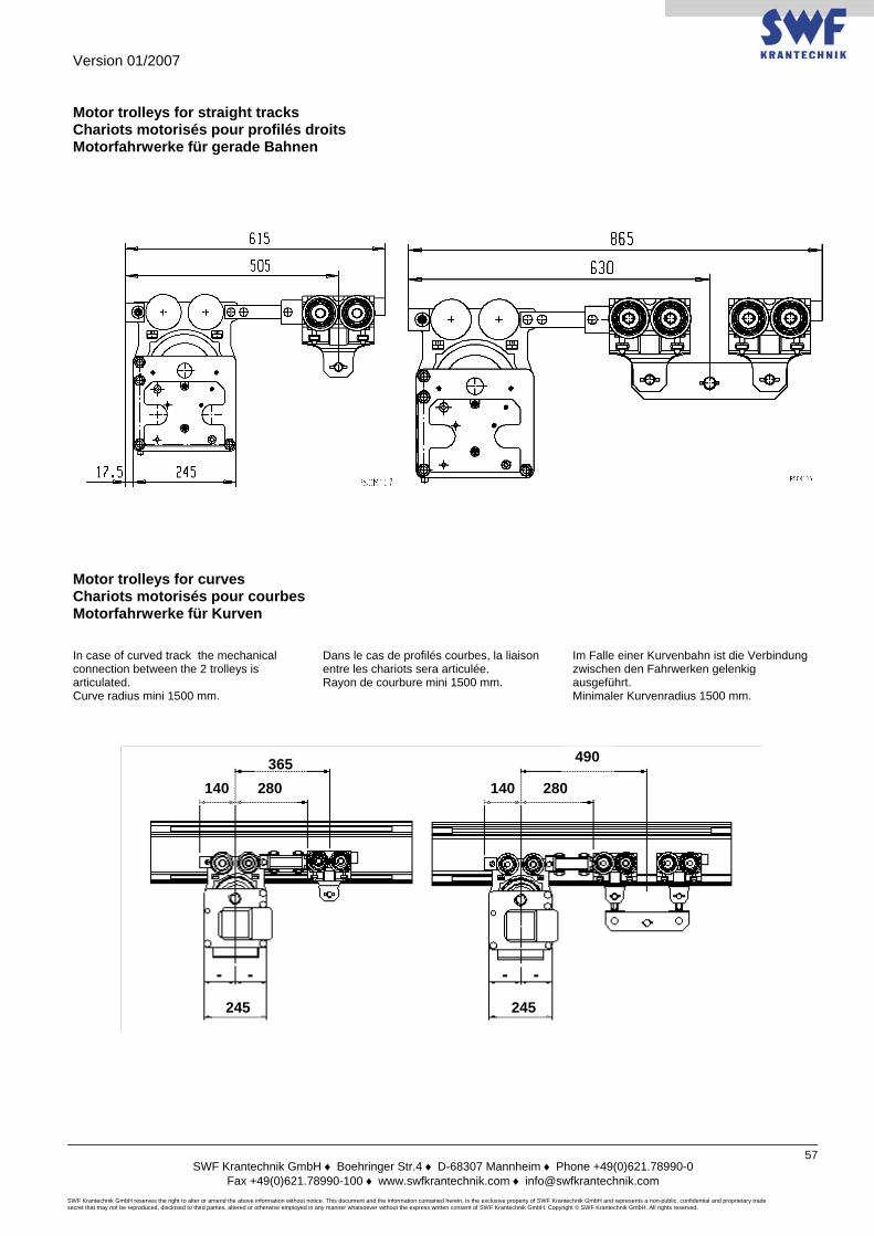
Version 01/2007
SWF Krantechnik GmbH ♦ Boehringer Str.4 ♦ D-68307 Mannheim ♦ Phone +49(0)621.78990-0
Fax +49(0)621.78990-100 ♦ www.swfkrantechnik.com ♦ [email protected] SWF Krantechnik GmbH reserves the right to alter or amend the above information without notice. This document and the information contained herein, is the exclusive property of SWF Krantechnik GmbH and represents a non-public, confidential and proprietary trade secret that may not be reproduced, disclosed to third parties, altered or otherwise employed in any manner whatsoever without the express written consent of SWF Krantechnik GmbH. Copyright © SWF Krantechnik GmbH. All rights reserved.
57
Motor trolleys for straight tracks Chariots motorisés pour profilés droits Motorfahrwerke für gerade Bahnen
Motor trolleys for curves Chariots motorisés pour courbes Motorfahrwerke für Kurven In case of curved track the mechanical connection between the 2 trolleys is articulated. Curve radius mini 1500 mm.
Dans le cas de profilés courbes, la liaison entre les chariots sera articulée. Rayon de courbure mini 1500 mm.
Im Falle einer Kurvenbahn ist die Verbindung zwischen den Fahrwerken gelenkig ausgeführt. Minimaler Kurvenradius 1500 mm.
490
280 280 140 140 365
245 245
Version 01/2007
SWF Krantechnik GmbH ♦ Boehringer Str.4 ♦ D-68307 Mannheim ♦ Phone +49(0)621.78990-0
Fax +49(0)621.78990-100 ♦ www.swfkrantechnik.com ♦ [email protected] SWF Krantechnik GmbH reserves the right to alter or amend the above information without notice. This document and the information contained herein, is the exclusive property of SWF Krantechnik GmbH and represents a non-public, confidential and proprietary trade secret that may not be reproduced, disclosed to third parties, altered or otherwise employed in any manner whatsoever without the express written consent of SWF Krantechnik GmbH. Copyright © SWF Krantechnik GmbH. All rights reserved.
58
Technical data for TMU motor Données techniques du moteur TMU Technische Daten des TMU Motors The TMU units are driven with fixed voltages and frequencies. The technical data are therefore the same for all line voltages.
Les moteurs TMU utilisent des tensions et des fréquences fixes. Les données techniques sont donc identiques pour toutes les plages d’alimentation.
Die TMU besitzen nur einen Betriebspannung- und Frequenzbereich. Aus diesem Grund die technischen Angaben für alle Spannungsbereiche gültig.
The scope of standard power supply covers voltages from 380 V to 480 V under frequency 50 or 60 Hz. In case of power voltages outside of the range (mini 230 V, maxi 600 V), transformers are supplied.
La plage des alimentations standard couvre toutes les tensions de 380 V à 480 V, fréquence 50 ou 60 Hz. En dehors de cette plage de tensions (minimum 230 V, maximum 600 V), des transformateurs sont fournis.
Der Standardbetriebsspannung reicht von 380 bis 480 V bei 50 oder 60 Hz. Ausserhalb dieser Standardbetriebsspannung (230 bis 600V) wird ein Transformator vorgeschaltet.
Motor code / Code moteur / Motorbezeichnung MF06MK200
Duty factor / Facteur de marche / Einschaltdauer S3-40%
Speed control / Type de contrôle / Mode inverter
Inverter supply voltage / Alimentation variateur / Stromeinspeisung des Inverters V 380-480 440-480
Motor voltage / Alimentation moteur / Stromeinspeisung des Motors V 400 460
Frequency / Fréquence / Frequenz Hz 100 120
Synchronous speed / Vitesse de synchronisation / Synchrongeschw. RPM 3000 3600
Nominal speed / Vitesse nominale / Nenngeschw. RPM 2855 3430
Brake torque / Couple de feinage / Bremsmoment Nm 2 2
Starting torque / Couple de démarrage / Anlaufmoment Nm 3.0 2.9
Starting current / Intensité de démarrage / Anlaufmoment A 4.2 4.3
Maximum torque / Couple maxi / Höchstmoment Nm 3.0 2.9
Speed at max. torque / Vitesse au couple maxi / Geschw. bei Höchstmoment RPM 0 0
80% of max. torque / 80 % du couple maxi / 80 % des Höchstmoments Nm 2.4 2.4
Speed at 80% torque / Vitesse à 80 % du couple maxi / Geschw. bei 80 % des Höchstmoments RPM 2200 2600
Current at 80% torque / Intensité à 80 % du couple maxi / Strom bei 80 % des Höchstmoments A 2.1 2.1
Starting power factor / Facteur de démarrage / Anlauffaktor 0.72 0.70
Weight / Poids / Gewicht kg 10 10
No-load current / Intensité sans charge / Strom ohne Last A 1.0 1.0
Stator resistance at 20 °C / Résistance des enroulements à 20° C / Wicklungwiderstand bei 20° C Ω 34 34
Nominal power / Puissance nominale / Nennleistung kW 0.3 0.37
Nominal current / Intensité nominale / Nennstrom A 1.2 1.2
Power factor / Facteur puissance / Leistungsfaktor 0.57 0.59
Efficiency / Efficience / Wirkungsgrad 0.65 0.65
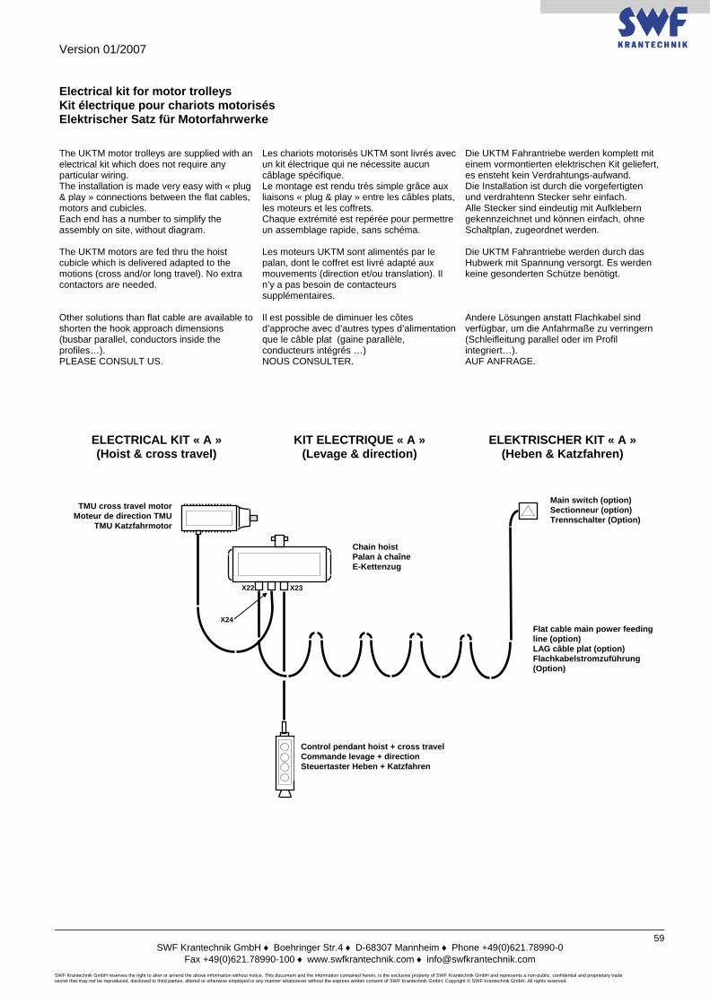
Version 01/2007
SWF Krantechnik GmbH ♦ Boehringer Str.4 ♦ D-68307 Mannheim ♦ Phone +49(0)621.78990-0
Fax +49(0)621.78990-100 ♦ www.swfkrantechnik.com ♦ [email protected] SWF Krantechnik GmbH reserves the right to alter or amend the above information without notice. This document and the information contained herein, is the exclusive property of SWF Krantechnik GmbH and represents a non-public, confidential and proprietary trade secret that may not be reproduced, disclosed to third parties, altered or otherwise employed in any manner whatsoever without the express written consent of SWF Krantechnik GmbH. Copyright © SWF Krantechnik GmbH. All rights reserved.
59
Electrical kit for motor trolleys Kit électrique pour chariots motorisés Elektrischer Satz für Motorfahrwerke The UKTM motor trolleys are supplied with an electrical kit which does not require any particular wiring. The installation is made very easy with « plug & play » connections between the flat cables, motors and cubicles. Each end has a number to simplify the assembly on site, without diagram.
Les chariots motorisés UKTM sont livrés avec un kit électrique qui ne nécessite aucun câblage spécifique. Le montage est rendu très simple grâce aux liaisons « plug & play » entre les câbles plats, les moteurs et les coffrets. Chaque extrémité est repérée pour permettre un assemblage rapide, sans schéma.
Die UKTM Fahrantriebe werden komplett mit einem vormontierten elektrischen Kit geliefert, es ensteht kein Verdrahtungs-aufwand. Die Installation ist durch die vorgefertigten und verdrahtenn Stecker sehr einfach. Alle Stecker sind eindeutig mit Aufklebern gekennzeichnet und können einfach, ohne Schaltplan, zugeordnet werden.
The UKTM motors are fed thru the hoist cubicle which is delivered adapted to the motions (cross and/or long travel). No extra contactors are needed.
Les moteurs UKTM sont alimentés par le palan, dont le coffret est livré adapté aux mouvements (direction et/ou translation). Il n’y a pas besoin de contacteurs supplémentaires.
Die UKTM Fahrantriebe werden durch das Hubwerk mit Spannung versorgt. Es werden keine gesonderten Schütze benötigt.
Other solutions than flat cable are available to shorten the hook approach dimensions (busbar parallel, conductors inside the profiles…). PLEASE CONSULT US.
Il est possible de diminuer les côtes d’approche avec d’autres types d’alimentation que le câble plat (gaine parallèle, conducteurs intégrés …) NOUS CONSULTER.
Andere Lösungen anstatt Flachkabel sind verfügbar, um die Anfahrmaße zu verringern (Schleifleitung parallel oder im Profil integriert…). AUF ANFRAGE.
ELECTRICAL KIT « A » (Hoist & cross travel)
KIT ELECTRIQUE « A » (Levage & direction)
ELEKTRISCHER KIT « A » (Heben & Katzfahren)
TMU cross travel motor Moteur de direction TMU
TMU Katzfahrmotor
X23
X24
X22
Control pendant hoist + cross travel Commande levage + direction Steuertaster Heben + Katzfahren
Main switch (option) Sectionneur (option) Trennschalter (Option)
Flat cable main power feeding line (option) LAG câble plat (option) Flachkabelstromzuführung (Option)
Chain hoist Palan à chaîne E-Kettenzug
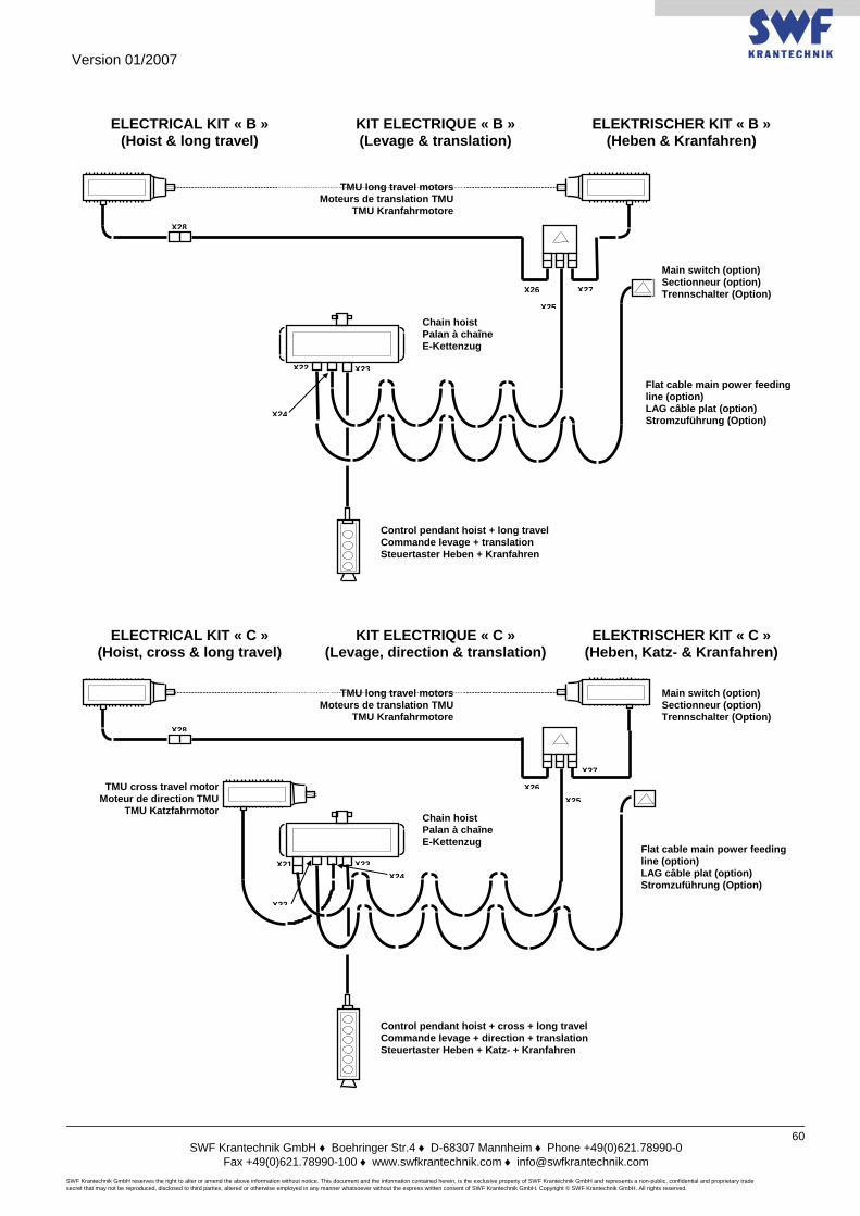
Version 01/2007
SWF Krantechnik GmbH ♦ Boehringer Str.4 ♦ D-68307 Mannheim ♦ Phone +49(0)621.78990-0
Fax +49(0)621.78990-100 ♦ www.swfkrantechnik.com ♦ [email protected] SWF Krantechnik GmbH reserves the right to alter or amend the above information without notice. This document and the information contained herein, is the exclusive property of SWF Krantechnik GmbH and represents a non-public, confidential and proprietary trade secret that may not be reproduced, disclosed to third parties, altered or otherwise employed in any manner whatsoever without the express written consent of SWF Krantechnik GmbH. Copyright © SWF Krantechnik GmbH. All rights reserved.
60
ELECTRICAL KIT « B »
(Hoist & long travel) KIT ELECTRIQUE « B » (Levage & translation)
ELEKTRISCHER KIT « B » (Heben & Kranfahren)
ELECTRICAL KIT « C » (Hoist, cross & long travel)
KIT ELECTRIQUE « C » (Levage, direction & translation)
ELEKTRISCHER KIT « C » (Heben, Katz- & Kranfahren)
TMU cross travel motor Moteur de direction TMU
TMU Katzfahrmotor
X26X25
X27
X28
X21 X23X24
X22
Main switch (option) Sectionneur (option) Trennschalter (Option)
Chain hoist Palan à chaîne E-Kettenzug
Flat cable main power feeding line (option) LAG câble plat (option) Stromzuführung (Option)
Control pendant hoist + cross + long travel Commande levage + direction + translation Steuertaster Heben + Katz- + Kranfahren
TMU long travel motors Moteurs de translation TMU
TMU Kranfahrmotore
Flat cable main power feeding line (option) LAG câble plat (option) Stromzuführung (Option)
X26
X25
X27
X28
X23
X24
X22
Main switch (option) Sectionneur (option) Trennschalter (Option)
Chain hoist Palan à chaîne E-Kettenzug
Control pendant hoist + long travel Commande levage + translation Steuertaster Heben + Kranfahren
TMU long travel motors Moteurs de translation TMU
TMU Kranfahrmotore
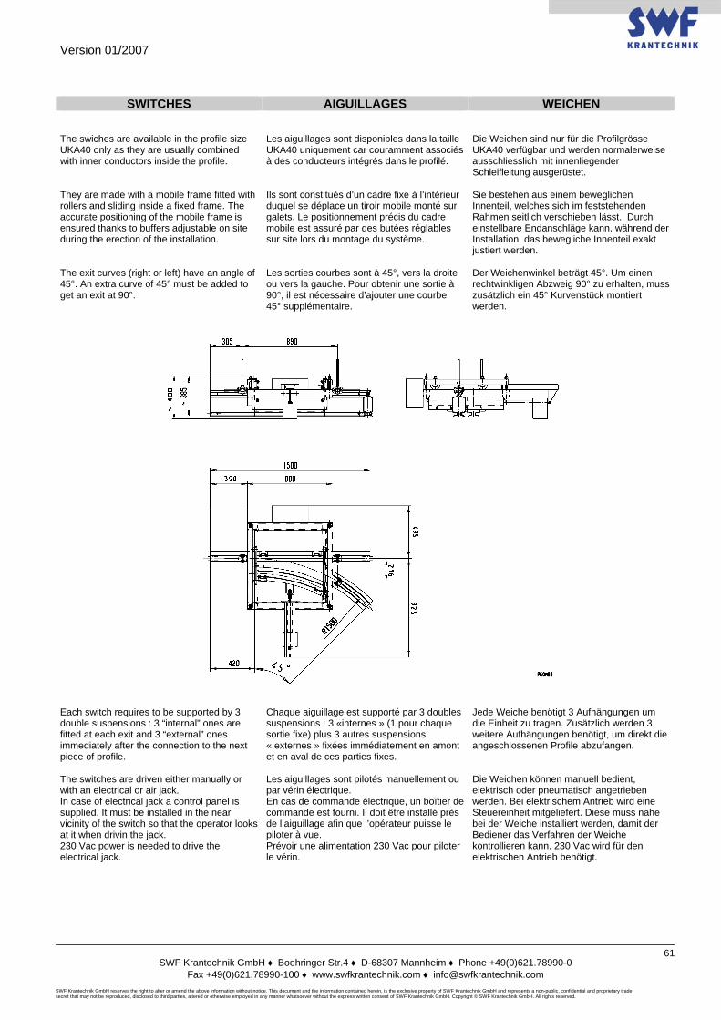
Version 01/2007
SWF Krantechnik GmbH ♦ Boehringer Str.4 ♦ D-68307 Mannheim ♦ Phone +49(0)621.78990-0
Fax +49(0)621.78990-100 ♦ www.swfkrantechnik.com ♦ [email protected] SWF Krantechnik GmbH reserves the right to alter or amend the above information without notice. This document and the information contained herein, is the exclusive property of SWF Krantechnik GmbH and represents a non-public, confidential and proprietary trade secret that may not be reproduced, disclosed to third parties, altered or otherwise employed in any manner whatsoever without the express written consent of SWF Krantechnik GmbH. Copyright © SWF Krantechnik GmbH. All rights reserved.
61
SWITCHES AIGUILLAGES WEICHEN
The swiches are available in the profile size UKA40 only as they are usually combined with inner conductors inside the profile.
Les aiguillages sont disponibles dans la taille UKA40 uniquement car couramment associés à des conducteurs intégrés dans le profilé.
Die Weichen sind nur für die Profilgrösse UKA40 verfügbar und werden normalerweise ausschliesslich mit innenliegender Schleifleitung ausgerüstet.
They are made with a mobile frame fitted with rollers and sliding inside a fixed frame. The accurate positioning of the mobile frame is ensured thanks to buffers adjustable on site during the erection of the installation.
Ils sont constitués d’un cadre fixe à l’intérieur duquel se déplace un tiroir mobile monté sur galets. Le positionnement précis du cadre mobile est assuré par des butées réglables sur site lors du montage du système.
Sie bestehen aus einem beweglichen Innenteil, welches sich im feststehenden Rahmen seitlich verschieben lässt. Durch einstellbare Endanschläge kann, während der Installation, das bewegliche Innenteil exakt justiert werden.
The exit curves (right or left) have an angle of 45°. An extra curve of 45° must be added to get an exit at 90°.
Les sorties courbes sont à 45°, vers la droite ou vers la gauche. Pour obtenir une sortie à 90°, il est nécessaire d’ajouter une courbe 45° supplémentaire.
Der Weichenwinkel beträgt 45°. Um einen rechtwinkligen Abzweig 90° zu erhalten, muss zusätzlich ein 45° Kurvenstück montiert werden.
Each switch requires to be supported by 3 double suspensions : 3 “internal” ones are fitted at each exit and 3 “external” ones immediately after the connection to the next piece of profile.
Chaque aiguillage est supporté par 3 doubles suspensions : 3 «internes » (1 pour chaque sortie fixe) plus 3 autres suspensions « externes » fixées immédiatement en amont et en aval de ces parties fixes.
Jede Weiche benötigt 3 Aufhängungen um die Einheit zu tragen. Zusätzlich werden 3 weitere Aufhängungen benötigt, um direkt die angeschlossenen Profile abzufangen.
The switches are driven either manually or with an electrical or air jack. In case of electrical jack a control panel is supplied. It must be installed in the near vicinity of the switch so that the operator looks at it when drivin the jack. 230 Vac power is needed to drive the electrical jack.
Les aiguillages sont pilotés manuellement ou par vérin électrique. En cas de commande électrique, un boîtier de commande est fourni. Il doit être installé près de l’aiguillage afin que l’opérateur puisse le piloter à vue. Prévoir une alimentation 230 Vac pour piloter le vérin.
Die Weichen können manuell bedient, elektrisch oder pneumatisch angetrieben werden. Bei elektrischem Antrieb wird eine Steuereinheit mitgeliefert. Diese muss nahe bei der Weiche installiert werden, damit der Bediener das Verfahren der Weiche kontrollieren kann. 230 Vac wird für den elektrischen Antrieb benötigt.
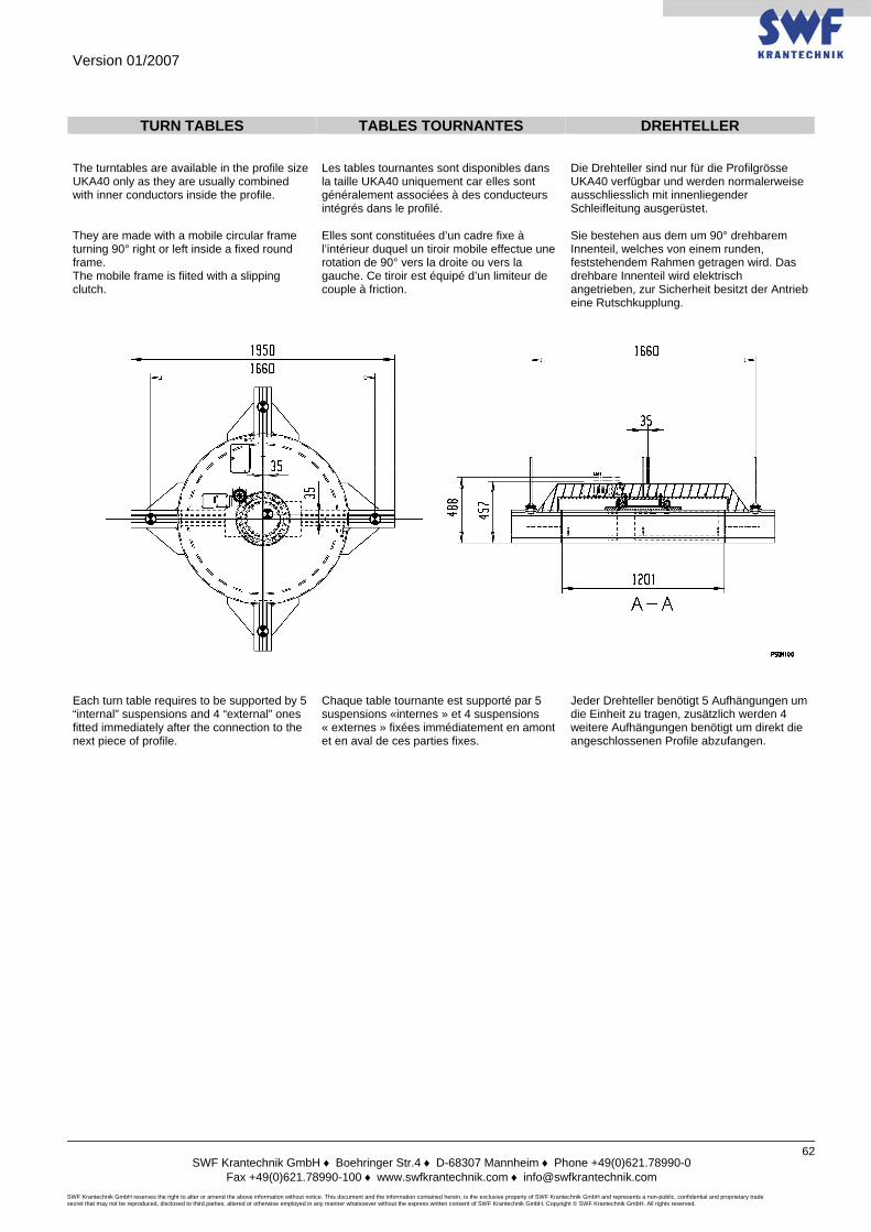
Version 01/2007
SWF Krantechnik GmbH ♦ Boehringer Str.4 ♦ D-68307 Mannheim ♦ Phone +49(0)621.78990-0
Fax +49(0)621.78990-100 ♦ www.swfkrantechnik.com ♦ [email protected] SWF Krantechnik GmbH reserves the right to alter or amend the above information without notice. This document and the information contained herein, is the exclusive property of SWF Krantechnik GmbH and represents a non-public, confidential and proprietary trade secret that may not be reproduced, disclosed to third parties, altered or otherwise employed in any manner whatsoever without the express written consent of SWF Krantechnik GmbH. Copyright © SWF Krantechnik GmbH. All rights reserved.
62
TURN TABLES TABLES TOURNANTES DREHTELLER
The turntables are available in the profile size UKA40 only as they are usually combined with inner conductors inside the profile.
Les tables tournantes sont disponibles dans la taille UKA40 uniquement car elles sont généralement associées à des conducteurs intégrés dans le profilé.
Die Drehteller sind nur für die Profilgrösse UKA40 verfügbar und werden normalerweise ausschliesslich mit innenliegender Schleifleitung ausgerüstet.
They are made with a mobile circular frame turning 90° right or left inside a fixed round frame. The mobile frame is fiited with a slipping clutch.
Elles sont constituées d’un cadre fixe à l’intérieur duquel un tiroir mobile effectue une rotation de 90° vers la droite ou vers la gauche. Ce tiroir est équipé d’un limiteur de couple à friction.
Sie bestehen aus dem um 90° drehbarem Innenteil, welches von einem runden, feststehendem Rahmen getragen wird. Das drehbare Innenteil wird elektrisch angetrieben, zur Sicherheit besitzt der Antrieb eine Rutschkupplung.
Each turn table requires to be supported by 5 “internal” suspensions and 4 “external” ones fitted immediately after the connection to the next piece of profile.
Chaque table tournante est supporté par 5 suspensions «internes » et 4 suspensions « externes » fixées immédiatement en amont et en aval de ces parties fixes.
Jeder Drehteller benötigt 5 Aufhängungen um die Einheit zu tragen, zusätzlich werden 4 weitere Aufhängungen benötigt um direkt die angeschlossenen Profile abzufangen.