Embed Size (px)
Citation preview

12Pneumatic Conveying in theAluminum Industry
1 INTRODUCTION
The aluminum industry employs pneumatic conveying widely for its materialshandling processes. As with many industries, there is economy in scale, and soindividual plants tend to be very large. It is still very much an expanding industry,and an industry that most large countries in the world like to have as part of theirindustrial infrastructure, particularly if cheap power is available from hydro-electric sources or from surplus gas reserves.
The economy of scale is such that alumina is one of the major bulk solidsthat is widely transported around the world by bulk carrier. At ports, ship off-loading systems based on pneumatic conveying of the material are commonlyemployed, such as that depicted in Figure 1.7. Over-land transport is generally byrail vehicles and these often have the capability of being pressurized to about 30lbf/in" gauge so that they can be off-loaded by positive pressure conveying sys-tems in a reasonably short period of time.
1.1 Systems and Components
The first point to note about alumina is that it is a very abrasive material. As aconsequence this must feature prominently in all decisions made with regard to theselection of systems and components.
Copyright 2004 by Marcel Dekker, Inc. All Rights Reserved.

366 Chapter 12
This is one of the industries that tends to employ fluidized motion convey-ing systems. This type of conveying system was introduced in section 7 of Chapter1 and are considered in some detail in Chapter 18. Air-assisted gravity conveyorshave been quite widely used for fifty years or more, but the more recent innova-tion of full channel conveyors are gaining wider acceptance for alumina. A par-ticular advantage of this type of system is that the air requirements are very lowand the transport velocity is also very low, and so problems of wear associatedwith alumina are significantly reduced.
This is also an industry where innovatory pneumatic conveying systems areemployed. This type of system was introduced in section 6 of Chapter 1 and areconsidered in more detail in Chapter 17. Plug forming systems based on internalby-pass pipes are probably the most commonly used system. This, once again, isas a consequence of the abrasive nature of the materials conveyed.
This type of system, however, should only be used when actually required,and this is dictated by the grade of the material. If a material has good air retentionproperties it will convey quite naturally in dense phase and at low velocity in aconventional pneumatic conveying system, and an innovatory system would bequite unnecessary.
With regard to pipeline feeding devices, the ideal requirement is that thefeeder should have no moving parts, particularly if there is a pressure drop acrossthe feeder. Blow tanks, therefore, are widely used. If it is necessary to used a ro-tary valve then it will have to be made of appropriate wear resistant materials, forboth the rotor and casing, and an increase in air leakage with respect to time mustbe anticipated for the feeder.
2 MATERIAL GRADE
Alumina is another material that comes in a range of grades, and the grades aresuch that the material may be a powder having good air retention properties, inwhich case it may be capable of being conveyed in dense phase. Alternatively, if itcomes as a fine granular material with very poor air retention it will probably onlybe capable of being conveyed in dilute phase in a conventional pneumatic convey-ing system. It is a fine division between the two, as was considered in the previouschapter, with regard to the degradation of fine granular materials.
Alumina in fine powdered form is often referred to as floury alumina and isgenerally capable of being conveyed naturally in dense phase and hence at lowvelocity. Fine granular alumina is often referred to as sandy alumina and this isgenerally only capable of being conveyed in dilute phase suspension flow. Theconveying characteristics for two typical grades of alumina were presented in Fig-ure 9.11 in relation to the use of stepped pipelines for the conveying of diversematerials. In order to reinforce, at the outset, this important point of the influenceof material grade on pneumatic conveying performance, these conveying charac-teristics are reproduced here in Figure 12.1.
Copyright 2004 by Marcel Dekker, Inc. All Rights Reserved.

Aluminum Industry Materials 367
Conveying LinePressure Drop - lbf/in2
ConveyingLimit
50
40
[200 120 100 80
30
20
1003
0
SolidsLoading
Ratio
ooo
50'
Solids LoadingRatio
Conveying LinePressure Drop
- lbf/in2 /NO
(a)
0 40 80 120 160 200
Free Air Flow Rate - ft3/min(b)
0 40 80 120 160 200
Free Air Flow Rate - ft3/min
Figure 12.1 Conveying characteristics for (a) floury and (b) sandy grades of alumina.
A sketch of the two inch nominal bore pipeline through which these twomaterials were conveyed is presented in Figure 12.2 for reference. A high pressurebottom discharge blow tank was used to feed the materials into the pipeline.
Figure 12.2 Details of pipeline used for the conveying of the two grades of aluminapresented in figure 12.1.
Copyright 2004 by Marcel Dekker, Inc. All Rights Reserved.
368 Chapter 12
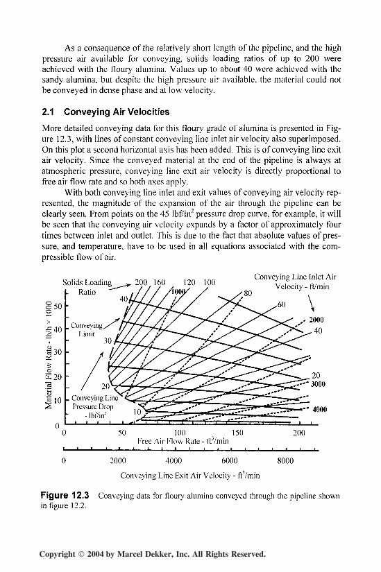
As a consequence of the relatively short length of the pipeline, and the highpressure air available for conveying, solids loading ratios of up to 200 wereachieved with the floury alumina. Values up to about 40 were achieved with thesandy alumina, but despite the high pressure air available, the material could notbe conveyed in dense phase and at low velocity.
2.1 Conveying Air Velocities
More detailed conveying data for this floury grade of alumina is presented in Fig-ure 12.3, with lines of constant conveying line inlet air velocity also superimposed.On this plot a second horizontal axis has been added. This is of conveying line exitair velocity. Since the conveyed material at the end of the pipeline is always atatmospheric pressure, conveying line exit air velocity is directly proportional tofree air flow rate and so both axes apply.
With both conveying line inlet and exit values of conveying air velocity rep-resented, the magnitude of the expansion of the air through the pipeline can beclearly seen. From points on the 45 lbf/in2 pressure drop curve, for example, it willbe seen that the conveying air velocity expands by a factor of approximately fourtimes between inlet and outlet. This is due to the fact that absolute values of pres-sure, and temperature, have to be used in all equations associated with the com-pressible flow of air.
200. 160 120 100Ratio
o 40^o50
40J 30
o
E20.2'C
I 10 Conveying LinePressure Drop
- lbf/in2
50 100 , 150 200Free Air Flow Rate - ftVmin
0 2000 4000 6000 8000
Conveying Line Exit Air Velocity - ftVmin
Figure 12.3 Conveying data for floury alumina conveyed through the pipeline shownin figure 12.2.
Copyright 2004 by Marcel Dekker, Inc. All Rights Reserved.

Aluminum Industry Materials 369
50ooo'40
730
$20_o
I 10
Solids Loading RatioConveying
Limit
Conveying Line Inlet AirVelocity - ft/min
sure Drop - lbf/in2
0 50 100 , 150 200Free Air Flow Rate - fP/min
0 2000 4000 6000 8000Conveying Line E\\t Air Velocity - ftj/min
Figure 12.4 Conveying data for sandy alumina conveyed through the pipeline shownin figure 12.2.
Similar data for the sandy grade of alumina is presented in Figure 12.4. Withthis material the minimum conveying air velocity was always above 2000 ft/min,and although the minimum value of conveying air velocity reduced slightly withincrease in air supply pressure, it was only marginal.
3 LOW PRESSURE CONVEYING
As mentioned before, low pressure dilute phase conveying data is generally in-cluded in the conveying characteristics derived with high pressure conveying fa-cilities, and so this data is equally valid. Care must be exercised, however, in en-suring that the appropriate minimum conveying air velocity is used.
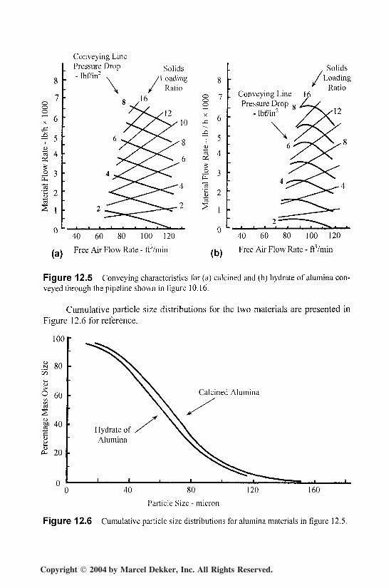
Both calcined alumina and hydrate of alumina have been conveyed throughthe Figure 10.16 pipeline of two inch nominal bore and 110 feet long. The lowpressure conveying characteristics for these two materials are presented in Figure12.5. In terms of conveying capability there is little difference between the twomaterials. The hydrate of alumina shows a tendency to a pressure minimum pointat low air flow rates and so the material flow rate in this region is slightly lowerthan that for the calcined alumina.
There is also a slight difference in minimum conveying air velocities be-tween the two materials. That for the calcined alumina is about 2300 ft/min andthat for the hydrate of alumina is about 2500 ft/min.
Copyright 2004 by Marcel Dekker, Inc. All Rights Reserved.
370 Chapter 12
ooo7 6_c
'f -*uta 4oi
3 3fc"c3| 2
S 1
0
Conveying LinePressure Drop- Ihf/in2
SolidsLoading
Ratio
(a)
40 60 80 100 120
Free Air Flow Rate - ft3/min
0 7
1 6.Q7 5oC3 il
g
— 3
0
(b)
Solids/Loading
^ D<it;^Conveying Line 1̂Pressure Drop
- lbf/in2
40 60 80 100 120
Free Air Flow Rate - ftVmin
Figure 12.5 Conveying characteristics for (a) calcined and (b) hydrate of alumina con-veyed through the pipeline shown in figure 10.16.
Cumulative particle size distributions for the two materials are presented inFigure 12.6 for reference.
100
a soonJ-H
1>
I 60S
40
20
Hydrate ofAlumina
40 80
Particle Size - micron
120 160
Figure 12.6 Cumulative particle size distributions for alumina materials in figure 12.5.
Copyright 2004 by Marcel Dekker, Inc. All Rights Reserved.

Aluminum Industry Materials 371
The mean particle size for the calcined alumina was about 66 /mi and thatfor the hydrate of alumina was about 60 jum. Granular materials, such as these,generally do not have sufficient air retention at this mean particle size for them tobe capable of being conveyed in dense phase in a conventional conveying system.It is unlikely, therefore, that either of these materials could be conveyed in densephase, even if a much higher air supply pressure were available. The particle den-sity for the calcined alumina was about 245 lb/ft j and that for the hydrate of alu-mina was about 150 lb/ftj.
4 HIGH PRESSURE CONVEYING
Both the calcined alumina and the hydrate of alumina have been conveyed in highpressure conveying facilities and it will be seen that they could not be conveyed indense phase and at low velocity, despite the high pressure. Data on a number ofother materials, such as aluminum fluoride, fluorspar and cryolite is also pre-sented.
4.1 Calcined Alumina
Conveying characteristics for calcined alumina conveyed through the Figure 7.13pipeline of three inch nominal bore are presented in Figure 12.7. The minimumvalue of conveying air velocity for the material was about 2300 ft/min.
25
§20
u
II10
OJ
I5
Solids Loading Ratio
Conveying Line PressureDrop - Ibf/in
0 100 200 300 400
Free Air Flow Rate - ft3 / min
Figure 12.7 Conveying characteristics for calcined alumina conveyed through thepipeline shown in figure 7.13.
Copyright 2004 by Marcel Dekker, Inc. All Rights Reserved.

372 Chapter 12
It will be seen that the maximum value of solids loading ratio for the cal-cined alumina was just over 12 in Figure 12.7 and that a similar value was ob-tained for the material in the low pressure test facility in Figure 12.5a. This is dueto the fact that the material could only be conveyed in dilute phase suspensionflow in both cases, and that the pressure gradients for the two pipelines were verysimilar. The Figure 10.16 pipeline was 110 feet long and the maximum value ofpressure drop was 8 Ibf/in2, and the Figure 7.13 pipeline was 310 feet long with amaximum pressure drop of 25 Ibf/in2. The approximate factors of three in terms ofpipeline length and pressure drop cancel each other out.
For reference and comparison purposes, a number of other materials con-veyed through the Figure 7.13 pipeline were presented in Figures 11.10 to 11.12,including potassium sulfate and dicalcium phosphate. These show a very widerange of conveying capabilities.
4.2 Hydrate of Alumina
A sketch of the high pressure pipeline facility in which the hydrate of alumina wasconveyed is presented in Figure 12.8. It was a two inch nominal bore pipeline, 320
feet in length and incorporated thirteen 90° bends, having a bend diameter, D, topipe bore, d, ratio of about 24:1. Once again the material was fed into the pipelineby means of a high pressure, top discharge blow tank, having a fluidizing mem-brane.
The conveying characteristics for the hydrate of alumina conveyed throughthis pipeline are presented in Figure 12.9.
Pipeline :length = 320ftbore = 2 inbends = 13 x 90°
Figure 12.8 Sketch of pipeline used for the high pressure conveying of hydrate ofalumina.
Copyright 2004 by Marcel Dekker, Inc. All Rights Reserved.

Aluminum Industry Materials 373
16
12
_ott,
ua 4S
Solids Loading Ratio
Conveying Line Pressuredrop - Ibf/in2
50 100 150
Free Air Flow Rate - ff / min
200
Figure 12.9 Conveying characteristics for hydrate of alumina conveyed through thepipeline shown in figure 12.8.
As with the calcined alumina, the hydrate of alumina could not be conveyedin dense phase either, despite the availability of high pressure air. The maximumvalue of solids loading ratio was about 16, which is similar to that achieved in thelow pressure conveying trials reported in Figure 12.5b, but this is due once againto the commonality of pressure gradients between the two sets of data. The mini-mum value of conveying air velocity was about 2500 ft/min once again.
4.3 Aluminum Fluoride
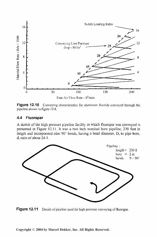
Similar data for aluminum fluoride conveyed through the Figure 12.8 pipeline ispresented in Figure 12.10. It will be seen that there is little difference between theconveying capability of the aluminum fluoride and the hydrate of alumina. Lowvelocity, dense phase conveying of this material was not a possibility in the con-veying system employed, as with the calcined alumina and hydrate of aluminareported above.
The minimum conveying air velocity for the aluminum fluoride was slightlyhigher at 2600 ft/min and material flow rates were slightly lower than those for thehydrate of alumina. The bulk density of the hydrate of alumina was about 75 lb/ft3
and that for the aluminum fluoride was about 90 lb/ft3. Such consistency in theconveying characteristics for a group of different materials is unusual.
Copyright 2004 by Marcel Dekker, Inc. All Rights Reserved.
374 Chapter 12
ooo
16
12
_o
Solids Loading Ratio
Conveying Line Pressuredrop - lbf/in2
50 100
Free Air Flow Rate - ft3/min
150 200
Figure 12.10 Conveying characteristics for aluminum fluoride conveyed through thepipeline shown in figure 12.8.
4.4 Fluorspar
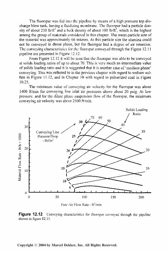
A sketch of the high pressure pipeline facility in which fluorspar was conveyed ispresented in Figure 12.11. It was a two inch nominal bore pipeline, 230 feet inlength and incorporated nine 90° bends, having a bend diameter, D, to pipe bore,d, ratio of about 24:1.
Pipeline :length = 230ftbore = 2 inbends = 9 x 90°
Figure 12.11 Details of pipeline used for high pressure conveying of fluorspar.
Copyright 2004 by Marcel Dekker, Inc. All Rights Reserved.
Aluminum Industry Materials 375
The fluorspar was fed into the pipeline by means of a high pressure top dis-charge blow tank, having a fluidizing membrane. The fluorspar had a particle den-sity of about 230 Ib/ft3 and a bulk density of about 100 Ib/ft3, which is the highestamong the group of materials considered in this chapter. The mean particle size ofthe material was approximately 66 micron. At this particle size the alumina couldnot be conveyed in dense phase, but the fluorspar had a degree of air retention.The conveying characteristics for the fluorspar conveyed through the Figure 12.11pipeline are presented in Figure 12.12.
From Figure 12.12 it will be seen that the fluorspar was able to be conveyedat solids loading ratios of up to about 70. This is very much an intermediate valueof solids loading ratio and it is suggested that it is another case of 'medium phase'conveying. This was referred to in the previous chapter with regard to sodium sul-fate in Figure 11.12, and in Chapter 10 with regard to pulverized coal in Figure10.25.
The minimum value of conveying air velocity for the fluorspar was about1400 ft/min for conveying line inlet air pressures above about 20 psig. At lowpressure, and for the dilute phase suspension flow of the fluorspar, the minimumconveying air velocity was about 2500 ft/min.
30
£ 20
•g 10<5
.70 60
Solids LoadingRatio
Conveying LinePressure Drop
- lbf/in2
1 1 I
15
10
50 100
Free Air Flow Rate - ftVmin
150 200
Figure 12.12 Conveying characteristics for fluorspar conveyed through the pipelineshown in figure 12.11.
Copyright 2004 by Marcel Dekker, Inc. All Rights Reserved.

376 Chapter 12
In the next chapter, conveying data for barite, bentonite and cement, eachconveyed through the Figure 12.11 pipeline, were all capable of being conveyed atsolids loading ratios of well over 100 and at conveying air velocities down to 600ft/min. Then in Chapter 14 data for silica sand having a mean particle size of ap-proximately 70 micron is presented and the maximum value of solids loading ratiois about 25, with a corresponding conveying line inlet air velocity of about 2300ft/min. These are typical of the operating limits for dense and dilute phase convey-ing for high pressure conveying in a pipeline of this length.
4.5 Cryolite
Cryolite is variously referred to as crushed bath and bath material. It has a meanparticle size typically about 0-1 inch but this depends upon the crushing process.The material generally has a very wide particle size distribution and often containsa high proportion of fines. The material reported here had a top size of/2 inch.
One of the pipelines through which this cryolite was conveyed is shown inFigure 12.13 for reference. It was two inch nominal bore, 165 feet in length andcontained eleven 90° bends, each having a D/d ratio of about 6:1. The materialwas fed into the pipeline by means of a high pressure blow tank. Since the materialhad such a large mean particle size and contained large lumps, in addition to beingvery abrasive, a blow tank was an ideal feeder for the cryolite.
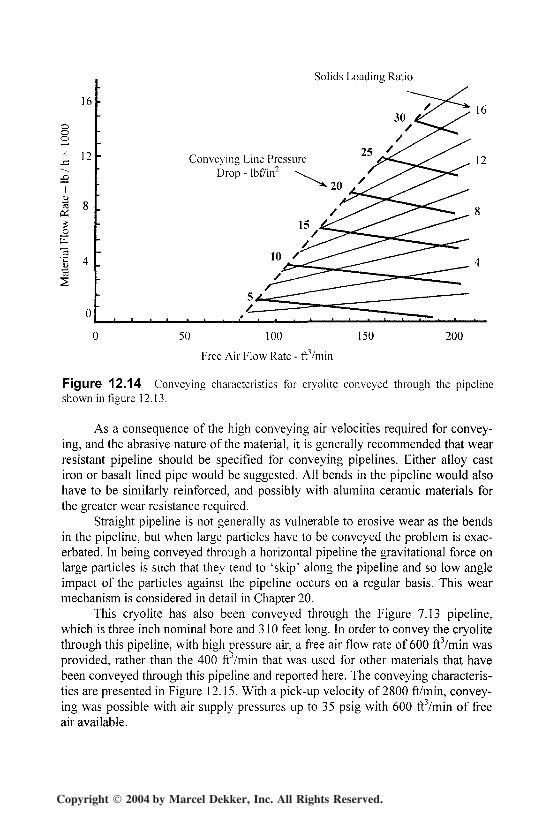
Conveying characteristics for this cryolite conveyed through the Figure12.13 pipeline are presented in Figure 12.14. As expected, the material could onlybe conveyed in dilute phase suspension flow. Despite the large particles in thematerial, and a particle density of about 190 lb/ftj, the minimum conveying airvelocity was-about 2800 ft/min. This relatively low value of pick-up velocity, forsuch a material, is helped significantly by the fact that the material had a very wideparticle size distribution and a large proportion of fines.
Pipeline :length = 165ftbore = 2 inbends = 11 x 90'D/d = 6
Figure 12.13 Sketch of pipeline used for the high pressure conveying of cryolite.
Copyright 2004 by Marcel Dekker, Inc. All Rights Reserved.
Aluminum Industry Materials 377
Solids Loading Ratio
16
12
ooo
I
"eST, 4
Conveying Line PressureDrop - Ibfi'in
0 50 100 150 200
Free Air Flow Rate - itVmin
Figure 12.14 Conveying characteristics for cryolite conveyed through the pipelineshown in figure 12.13.
As a consequence of the high conveying air velocities required for convey-ing, and the abrasive nature of the material, it is generally recommended that wearresistant pipeline should be specified for conveying pipelines. Either alloy castiron or basalt lined pipe would be suggested. All bends in the pipeline would alsohave to be similarly reinforced, and possibly with alumina ceramic materials forthe greater wear resistance required.
Straight pipeline is not generally as vulnerable to erosive wear as the bendsin the pipeline, but when large particles have to be conveyed the problem is exac-erbated. In being conveyed through a horizontal pipeline the gravitational force onlarge particles is such that they tend to 'skip' along the pipeline and so low angleimpact of the particles against the pipeline occurs on a regular basis. This wearmechanism is considered in detail in Chapter 20.
This cryolite has also been conveyed through the Figure 7.13 pipeline,which is three inch nominal bore and 310 feet long. In order to convey the cryolitethrough this pipeline, with high pressure air, a free air flow rate of 600 ftVmin wasprovided, rather than the 400 frYmin that was used for other materials that havebeen conveyed through this pipeline and reported here. The conveying characteris-tics are presented in Figure 12.15. With a pick-up velocity of 2800 ft/min, convey-ing was possible with air supply pressures up to 35 psig with 600 ftVmin of freeair available.
Copyright 2004 by Marcel Dekker, Inc. All Rights Reserved.

378 Chapter 12
40
ooo
30
(2 20
oE13| 10
CS
Solids Loading Ratio
Conveying Line PressureDrop - Ibt7in2
100 200 300 400
Free Air Flow Rate - ft3/min
500 600
Figure 12.15 Conveying characteristics for cryolite conveyed through the pipelineshown in figure 7.13.
Figure 12.15 clearly shows the influence of free air flow rate on the convey-ing capability of dilute phase conveying systems. With only 400 ftVmin themaximum value of air supply pressure that could be used would be about 20 psig,regardless of the fact that air was available at 100 psig. With only 200 ft3/min al-most nothing could be conveyed through the pipeline at all.
The conveying characteristics for calcined alumina conveyed through thissame pipeline were presented earlier in Figure 12.7. With only 400 ftVmin of freeair available for conveying, but with a lower pick-up velocity of 2300 ft/min, airsupply pressures up to about 25 psig could be employed. If the two sets of data arecompared it will be seen that a maximum of about 27,000 Ib/h of cryolite could beconveyed with a pressure drop of 25 lbf/in2, but only about 23,000 Ib/h of calcinedalumina could be conveyed with the same pressure drop.
Copyright 2004 by Marcel Dekker, Inc. All Rights Reserved.