Embed Size (px)
Citation preview
PK
S/P
SK
Pneumatic
Test Probes /
Switching Probes
0
1
23
4
5
6
0
1
23
4
5
6
1. Compressed air 0 bar, Plunger at home-position
2. 6 bar, Plunger shoots out, working-positionCompressed air
PKS-355 M 84
PKS-388 M 85
PSK-350 MScrew-in Pneumatic Test Probe 86
PKS-171 87
PKS-200 88
PKS-220 89
PKS-299 90
PKS-300 91
PKS-399 92
PKS-420 93
PKS Accessories 94+95
Technical Information Contents
Pneumatic Test Probes and
Switching Probes
Pneumatic Test Probes are operated with compressed air. Before activation,
the plunger is in the home position. On applying the compressed air, the
plunger shoots out. The spring inside the barrel retrieves the plunger after
releasing the compressed air.
Application Examples
– Individual contacting of single test points
– Can be controlled individually or in groups
– Contacting of test points, which are difficult to access
– Flexible application as a type of push-rod in Test Fixtures
– Movement of components in explosive areas
(instead of Electro-Motors)
Advantages
– Fixtureless contacting possible
– Later enhancement of test points (layout change) possible
– Individual set-up of the test procedures possible
– Quick set-up of flexible test requirements
– In the case of a small number of test points, cheap
alternative to a Test Fixture
– High level of contacting accuracy due to short installation
height and stationary basic set-up
84 All specifications are subject to change without prior notification
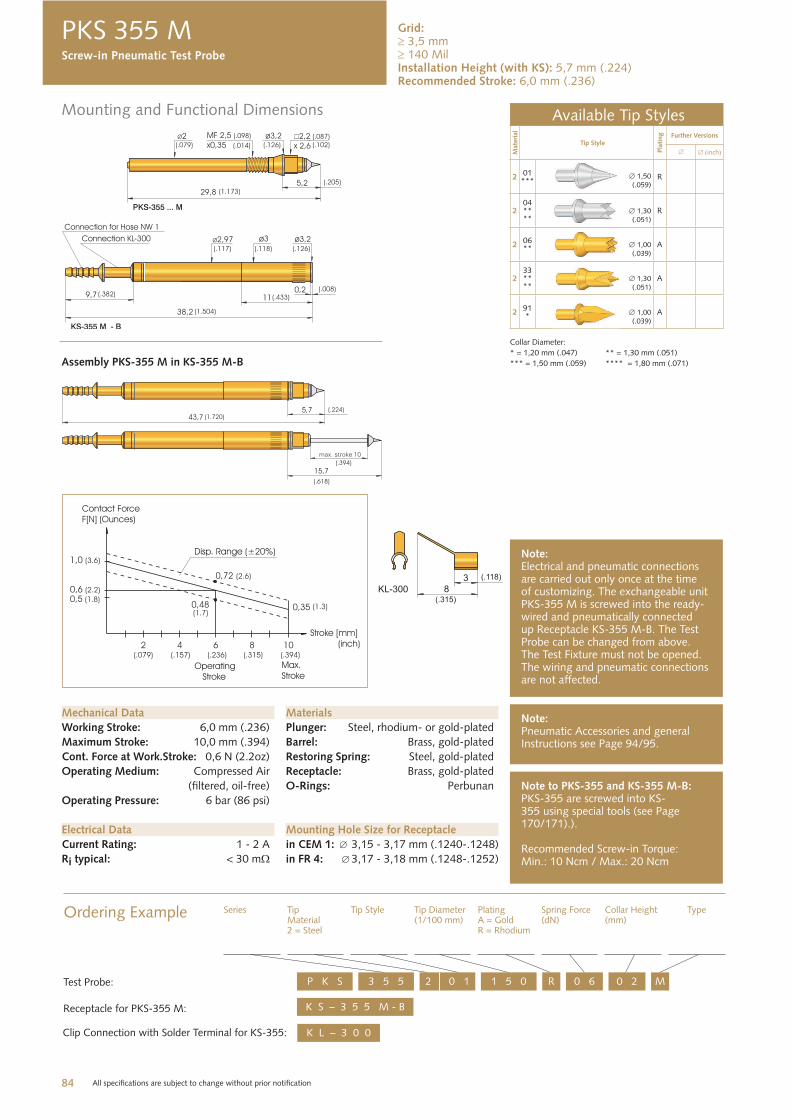
Mounting and Functional Dimensions
PKS 355 M
Available Tip Styles
Mate
rial
Tip Style
Pla
ting Further Versions
inch
201***
1,50(.059)
R
204****
1,30(.051)
R
206** 1,00
(.039)A
233****
1,30(.051)
A
291* 1,00
(.039)A
Collar Diameter:
* = 1,20 mm (.047) ** = 1,30 mm (.051)
*** = 1,50 mm (.059) **** = 1,80 mm (.071)
Mechanical Data
Working Stroke: 6,0 mm (.236)
Maximum Stroke: 10,0 mm (.394)
Cont. Force at Work.Stroke: 0,6 N (2.2oz)
Operating Medium: Compressed Air
(filtered, oil-free)
Operating Pressure: 6 bar (86 psi)
Electrical Data
Current Rating: 1 - 2 A
Ri typical: < 30 m
Mounting Hole Size for Receptacle
in CEM 1: 3,15 - 3,17 mm (.1240-.1248)
in FR 4: 3,17 - 3,18 mm (.1248-.1252)
Materials
Plunger: Steel, rhodium- or gold-plated
Barrel: Brass, gold-plated
Restoring Spring: Steel, gold-plated
Receptacle: Brass, gold-plated
O-Rings: Perbunan Note to PKS-355 and KS-355 M-B:PKS-355 are screwed into KS-355 using special tools (see Page 170/171).).
Recommended Screw-in Torque:Min.: 10 Ncm / Max.: 20 Ncm
Note:Electrical and pneumatic connections are carried out only once at the time of customizing. The exchangeable unit PKS-355 M is screwed into the ready- wired and pneumatically connected up Receptacle KS-355 M-B. The Test Probe can be changed from above. The Test Fixture must not be opened. The wiring and pneumatic connections are not affected.
Ordering Example Series TipMaterial2 = Steel
Tip Style Tip Diameter(1/100 mm)
PlatingA = GoldR = Rhodium
Spring Force(dN)
Collar Height(mm)
Type
K S – 3 5 5 M - B
3 5 5P K S 2 0 1 1 5 0 R M0 6 0 2
Receptacle for PKS-355 M:
Test Probe:
K L – 3 0 0 Clip Connection with Solder Terminal for KS-355:
Note:Pneumatic Accessories and general Instructions see Page 94/95.
Assembly PKS-355 M in KS-355 M-B
Screw-in Pneumatic Test Probe
Grid: 3,5 mm 140 Mil
Installation Height (with KS): 5,7 mm (.224) Recommended Stroke: 6,0 mm (.236)
85 All specifications are subject to change without prior notification
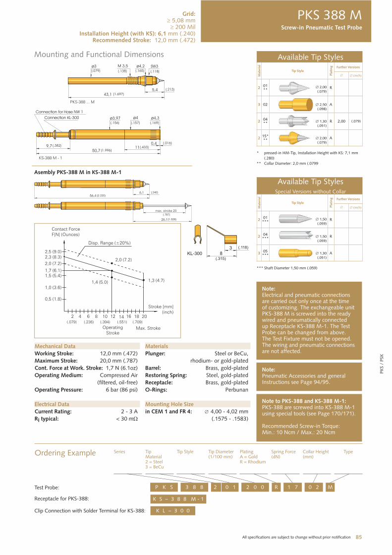
Mounting and Functional Dimensions
PK
S /
PSK
PKS 388 M
Available Tip Styles
Mate
rial
Tip Style
Pla
ting Further Versions
inch
201**
2,00(.079)
R
3 02 2,50 (.098)
A
204** 1,30
(.051) R 2,00 (.079)
215*** 2,00
(.079) A
* pressed-in HM-Tip, Installation Height with KS: 7,1 mm
(.280)
** Collar Diameter: 2,0 mm (.0799
Available Tip StylesSpecial Versions without Collar
Mat
eria
l
Tip Style
Pla
ting Further Versions
inch
201***
1,50 (.059)
R
204
*** 1,50(.059)
R
305
*** 1,30(.051)
A
*** Shaft Diameter 1,50 mm (.059)
Mechanical Data
Working Stroke: 12,0 mm (.472)
Maximum Stroke: 20,0 mm (.787)
Cont. Force at Work. Stroke: 1,7 N (6.1oz)
Operating Medium: Compressed Air
(filtered, oil-free)
Operating Pressure: 6 bar (86 psi)
Electrical Data
Current Rating: 2 - 3 A
Ri typical: < 30 m
Mounting Hole Size
in CEM 1 and FR 4: 4,00 - 4,02 mm
(.1575 - .1583)
Materials
Plunger: Steel or BeCu,
rhodium- or gold-plated
Barrel: Brass, gold-plated
Restoring Spring: Steel, gold-plated
Receptacle: Brass, gold-plated
O-Rings: Perbunan
Ordering Example Series TipMaterial2 = Steel 3 = BeCu
Tip Style Tip Diameter(1/100 mm)
PlatingA = GoldR = Rhodium
Spring Force(dN)
Collar Height(mm)
Type
3 8 8P K S 2 0 1 2 0 0 R M1 7 0 2Test Probe:
Note to PKS-388 and KS-388 M-1:PKS-388 are screwed into KS-388 M-1 using special tools (see Page 170/171).
Recommended Screw-in Torque:Min.: 10 Ncm / Max.: 20 Ncm
K S – 3 8 8 M - 1 Receptacle for PKS-388:
Note:Electrical and pneumatic connections are carried out only once at the time of customizing. The exchangeable unit PKS-388 M is screwed into the ready wired and pneumatically connected up Receptacle KS-388 M-1. The Test Probe can be changed from above. The Test Fixture must not be opened. The wiring and pneumatic connections are not affected.
K L – 3 0 0 Clip Connection with Solder Terminal for KS-388:
Asembly PKS-388 M in KS-388 M-1
Screw-in Pneumatic Test Probe
Grid: 5,08 mm
200 MilInstallation Height (with KS): 6,1 mm (.240)
Recommended Stroke: 12,0 mm (.472)
Note:Pneumatic Accessories and general Instructions see Page 94/95.
86 All specifications are subject to change without prior notification
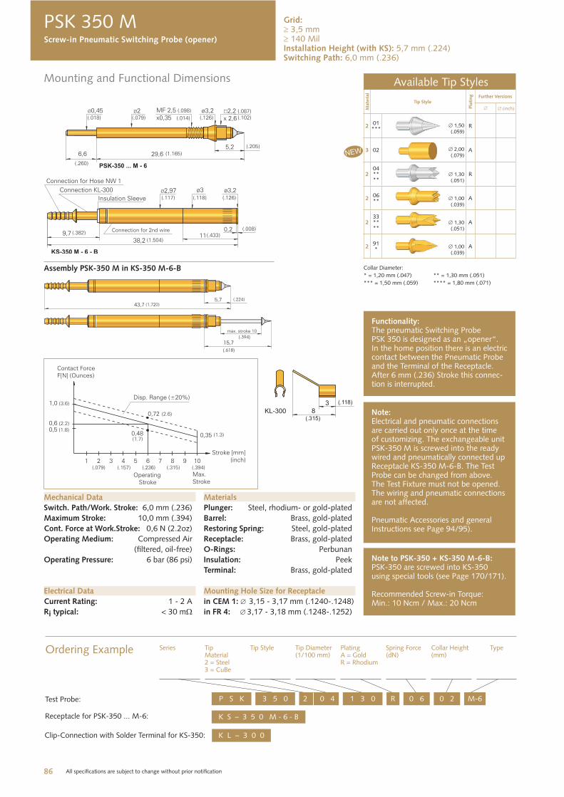
Mounting and Functional Dimensions
PSK 350 M
Available Tip Styles
Mate
rial
Tip Style
Pla
ting Further Versions
inch
201***
1,50(.059)
R
3 02 2,00(.079)
A
204****
1,30(.051)
R
206** 1,00
(.039)A
233****
1,30(.051)
A
291* 1,00
(.039)A
Collar Diameter:
* = 1,20 mm (.047) ** = 1,30 mm (.051)
*** = 1,50 mm (.059) **** = 1,80 mm (.071)
Mechanical Data
Switch. Path/Work. Stroke: 6,0 mm (.236)
Maximum Stroke: 10,0 mm (.394)
Cont. Force at Work.Stroke: 0,6 N (2.2oz)
Operating Medium: Compressed Air
(filtered, oil-free)
Operating Pressure: 6 bar (86 psi)
Electrical Data
Current Rating: 1 - 2 A
Ri typical: < 30 m
Mounting Hole Size for Receptacle
in CEM 1: 3,15 - 3,17 mm (.1240-.1248)
in FR 4: 3,17 - 3,18 mm (.1248-.1252)
Materials
Plunger: Steel, rhodium- or gold-plated
Barrel: Brass, gold-plated
Restoring Spring: Steel, gold-plated
Receptacle: Brass, gold-plated
O-Rings: Perbunan
Insulation: Peek
Terminal: Brass, gold-plated
Note to PSK-350 + KS-350 M-6-B:PSK-350 are screwed into KS-350 using special tools (see Page 170/171).
Recommended Screw-in Torque:Min.: 10 Ncm / Max.: 20 Ncm
Note:Electrical and pneumatic connections are carried out only once at the time of customizing. The exchangeable unit PSK-350 M is screwed into the ready wired and pneumatically connected up Receptacle KS-350 M-6-B. The Test Probe can be changed from above. The Test Fixture must not be opened. The wiring and pneumatic connections are not affected.
Pneumatic Accessories and general Instructions see Page 94/95).
Ordering Example Series TipMaterial2 = Steel3 = CuBe
Tip Style Tip Diameter(1/100 mm)
PlatingA = GoldR = Rhodium
Spring Force(dN)
Collar Height(mm)
Type
K S – 3 5 0 M - 6 - B
3 5 0P S K 2 0 4 1 3 0 R M-60 6 0 2
Receptacle for PSK-350 ... M-6:
Test Probe:
K L – 3 0 0 Clip-Connection with Solder Terminal for KS-350:
Functionality:The pneumatic Switching Probe PSK 350 is designed as an „opener“. In the home position there is an electric contact between the Pneumatic Probe and the Terminal of the Receptacle. After 6 mm (.236) Stroke this connec-tion is interrupted.
Assembly PSK-350 M in KS-350 M-6-B
Screw-in Pneumatic Switching Probe (opener)
Grid: 3,5 mm 140 Mil
Installation Height (with KS): 5,7 mm (.224)Switching Path: 6,0 mm (.236)
87 All specifications are subject to change without prior notification
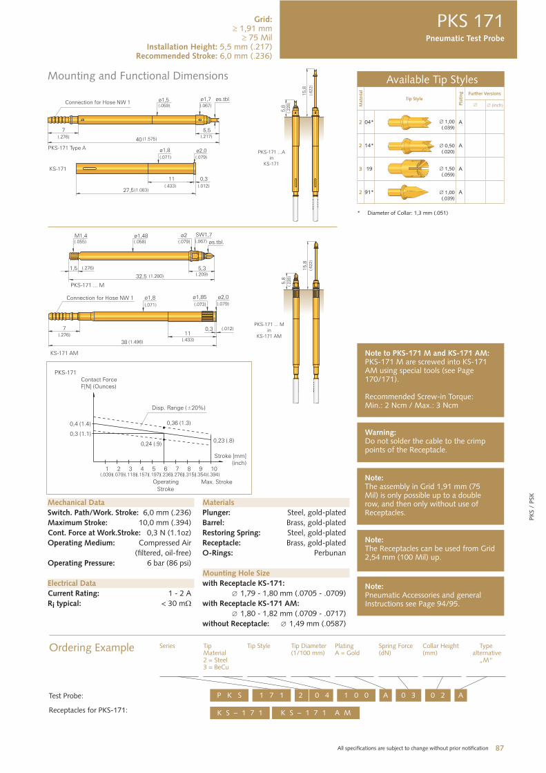
Mounting and Functional Dimensions
PK
S /
PSK
PKS 171
Available Tip Styles
Mate
rial
Tip Style
Pla
ting Further Versions
inch
2 04* 1,00 (.039)
A
2 14* 0,50(.020)
A
3 19 1,50(.059)
A
2 91* 1,00(.039)
A
* Diameter of Collar: 1,3 mm (.051)
Mechanical Data
Switch. Path/Work. Stroke: 6,0 mm (.236)
Maximum Stroke: 10,0 mm (.394)
Cont. Force at Work.Stroke: 0,3 N (1.1oz)
Operating Medium: Compressed Air
(filtered, oil-free)
Operating Pressure: 6 bar (86 psi)
Electrical Data
Current Rating: 1 - 2 A
Ri typical: < 30 m
Mounting Hole Size
with Receptacle KS-171:
1,79 - 1,80 mm (.0705 - .0709)
with Receptacle KS-171 AM:
1,80 - 1,82 mm (.0709 - .0717)
without Receptacle: 1,49 mm (.0587)
Materials
Plunger: Steel, gold-plated
Barrel: Brass, gold-plated
Restoring Spring: Steel, gold-plated
Receptacle: Brass, gold-plated
O-Rings: Perbunan
Note:The assembly in Grid 1,91 mm (75 Mil) is only possible up to a double row, and then only without use of Receptacles.
Ordering Example Series TipMaterial2 = Steel 3 = BeCu
Tip Style Tip Diameter(1/100 mm)
PlatingA = Gold
Spring Force(dN)
Collar Height(mm)
Type alternative
„M“
K S – 1 7 1
1 7 1P K S 2 0 4 1 0 0 A A0 3 0 2
Receptacles for PKS-171:
Test Probe:
Note:The Receptacles can be used from Grid 2,54 mm (100 Mil) up.
Note:Pneumatic Accessories and general Instructions see Page 94/95.
Warning:Do not solder the cable to the crimp points of the Receptacle.
Pneumatic Test Probe
Grid: 1,91 mm
75 Mil Installation Height: 5,5 mm (.217)
Recommended Stroke: 6,0 mm (.236)
K S – 1 7 1 A M
Note to PKS-171 M and KS-171 AM:PKS-171 M are screwed into KS-171 AM using special tools (see Page 170/171).
Recommended Screw-in Torque:Min.: 2 Ncm / Max.: 3 Ncm
88 All specifications are subject to change without prior notification
Mounting and Functional Dimensions
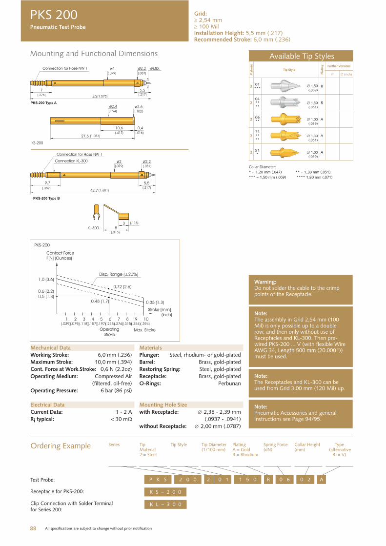
PKS 200
Available Tip Styles
Mate
rial
Tip Style
Pla
ting Further Versions
inch
201***
1,50(.059)
R
204****
1,30(.051)
R
206** 1,00
(.039)A
233****
1,30(.051)
A
291* 1,00
(.039)A
Collar Diameter:
* = 1,20 mm (.047) ** = 1,30 mm (.051)
*** = 1,50 mm (.059) **** 1,80 mm (.071)
Mechanical Data
Working Stroke: 6,0 mm (.236)
Maximum Stroke: 10,0 mm (.394)
Cont. Force at Work.Stroke: 0,6 N (2.2oz)
Operating Medium: Compressed Air
(filtered, oil-free)
Operating Pressure: 6 bar (86 psi)
Electrical Data
Current Data: 1 - 2 A
Ri typical: < 30 m
Mounting Hole Size
with Receptacle: 2,38 - 2,39 mm
(.0937 - .0941)
without Receptacle: 2,00 mm (.0787)
Materials
Plunger: Steel, rhodium- or gold-plated
Barrel: Brass, gold-plated
Restoring Spring: Steel, gold-plated
Receptacle: Brass, gold-plated
O-Rings: Perbunan
Note:The assembly in Grid 2,54 mm (100 Mil) is only possible up to a double row, and then only without use of Receptacles and KL-300. Then pre-wired PKS-200 ... V (with flexible Wire AWG 34, Length 500 mm (20.000“)) must be used.
Ordering Example Series TipMaterial2 = Steel
Tip Style Tip Diameter(1/100 mm)
PlatingA = GoldR = Rhodium
Spring Force(dN)
Collar Height(mm)
Type (alternative
B or V)
K S – 2 0 0
2 0 0P K S 2 0 1 1 5 0 R A0 6 0 2
Receptacle for PKS-200:
Test Probe:
Note:The Receptacles and KL-300 can be used from Grid 3,00 mm (120 Mil) up.
Note:Pneumatic Accessories and general Instructions see Page 94/95.
Warning:Do not solder the cable to the crimp points of the Receptacle.
K L – 3 0 0 Clip Connection with Solder Terminal for Series 200:
Pneumatic Test Probe
Grid: 2,54 mm 100 Mil
Installation Height: 5,5 mm (.217)Recommended Stroke: 6,0 mm (.236)
89 All specifications are subject to change without prior notification
Mounting and Functional Dimensions
PK
S /
PSK
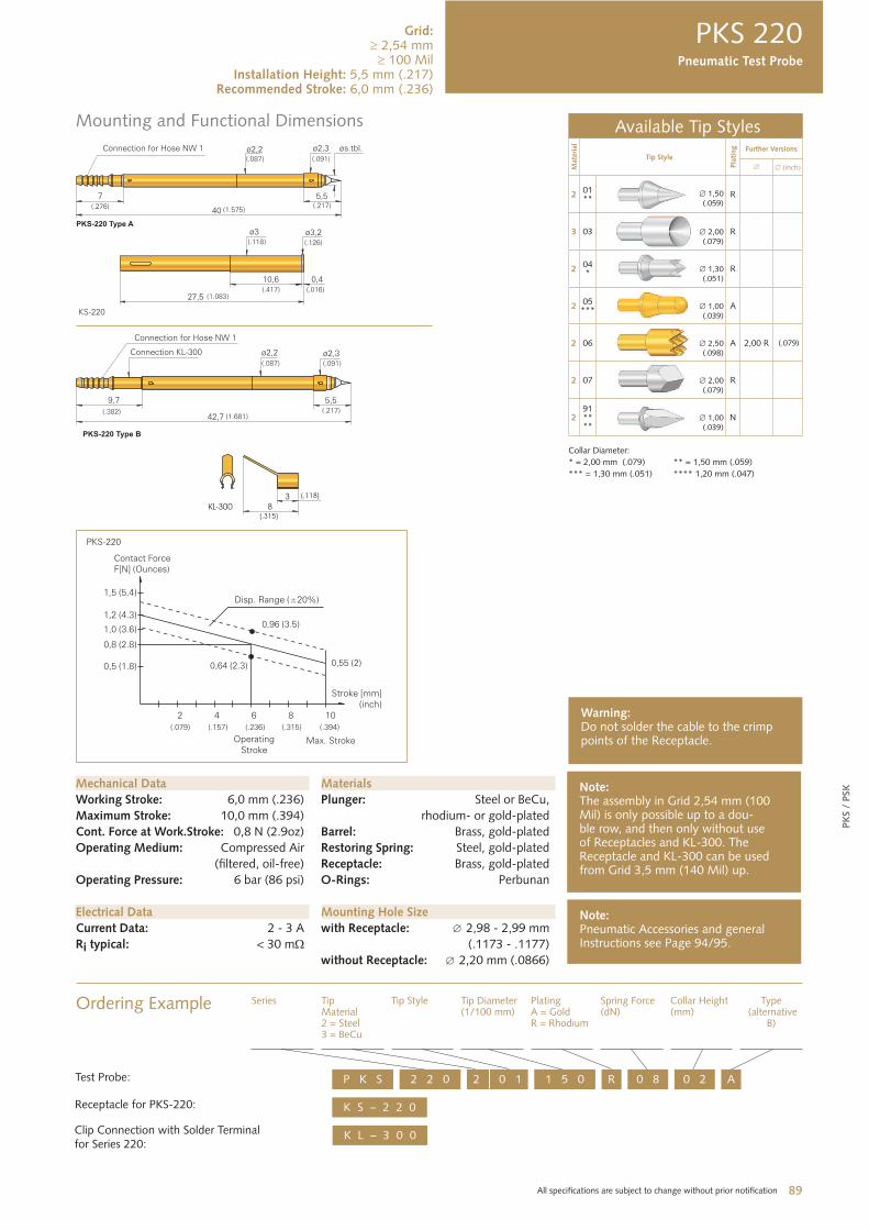
PKS 220
Available Tip Styles
Mate
rial
Tip Style
Pla
ting Further Versions
inch
201**
1,50(.059)
R
3 03 2,00(.079)
R
204* 1,30
(.051) R
205*** 1,00
(.039) A
2 06 2,50(.098)
A 2,00 R (.079)
2 07 2,00(.079)
R
291****
1,00 (.039)
N
Collar Diameter:
* = 2,00 mm (.079) ** = 1,50 mm (.059)
*** = 1,30 mm (.051) **** 1,20 mm (.047)
Mechanical Data
Working Stroke: 6,0 mm (.236)
Maximum Stroke: 10,0 mm (.394)
Cont. Force at Work.Stroke: 0,8 N (2.9oz)
Operating Medium: Compressed Air
(filtered, oil-free)
Operating Pressure: 6 bar (86 psi)
Electrical Data
Current Data: 2 - 3 A
Ri typical: < 30 m
Mounting Hole Size
with Receptacle: 2,98 - 2,99 mm
(.1173 - .1177)
without Receptacle: 2,20 mm (.0866)
Materials
Plunger: Steel or BeCu,
rhodium- or gold-plated
Barrel: Brass, gold-plated
Restoring Spring: Steel, gold-plated
Receptacle: Brass, gold-plated
O-Rings: Perbunan
Note:The assembly in Grid 2,54 mm (100 Mil) is only possible up to a dou-ble row, and then only without use of Receptacles and KL-300. The Receptacle and KL-300 can be used from Grid 3,5 mm (140 Mil) up.
Ordering Example Series TipMaterial2 = Steel 3 = BeCu
Tip Style Tip Diameter(1/100 mm)
PlatingA = GoldR = Rhodium
Spring Force(dN)
Collar Height(mm)
Type (alternative
B)
K S – 2 2 0
2 2 0P K S 2 0 1 1 5 0 R A0 8 0 2
Note:Pneumatic Accessories and general Instructions see Page 94/95.
Warning:Do not solder the cable to the crimp points of the Receptacle.
K L – 3 0 0
Pneumatic Test Probe
Grid: 2,54 mm
100 MilInstallation Height: 5,5 mm (.217)
Recommended Stroke: 6,0 mm (.236)
Receptacle for PKS-220:
Test Probe:
Clip Connection with Solder Terminal for Series 220:
90 All specifications are subject to change without prior notification
Mounting and Functional Dimensions
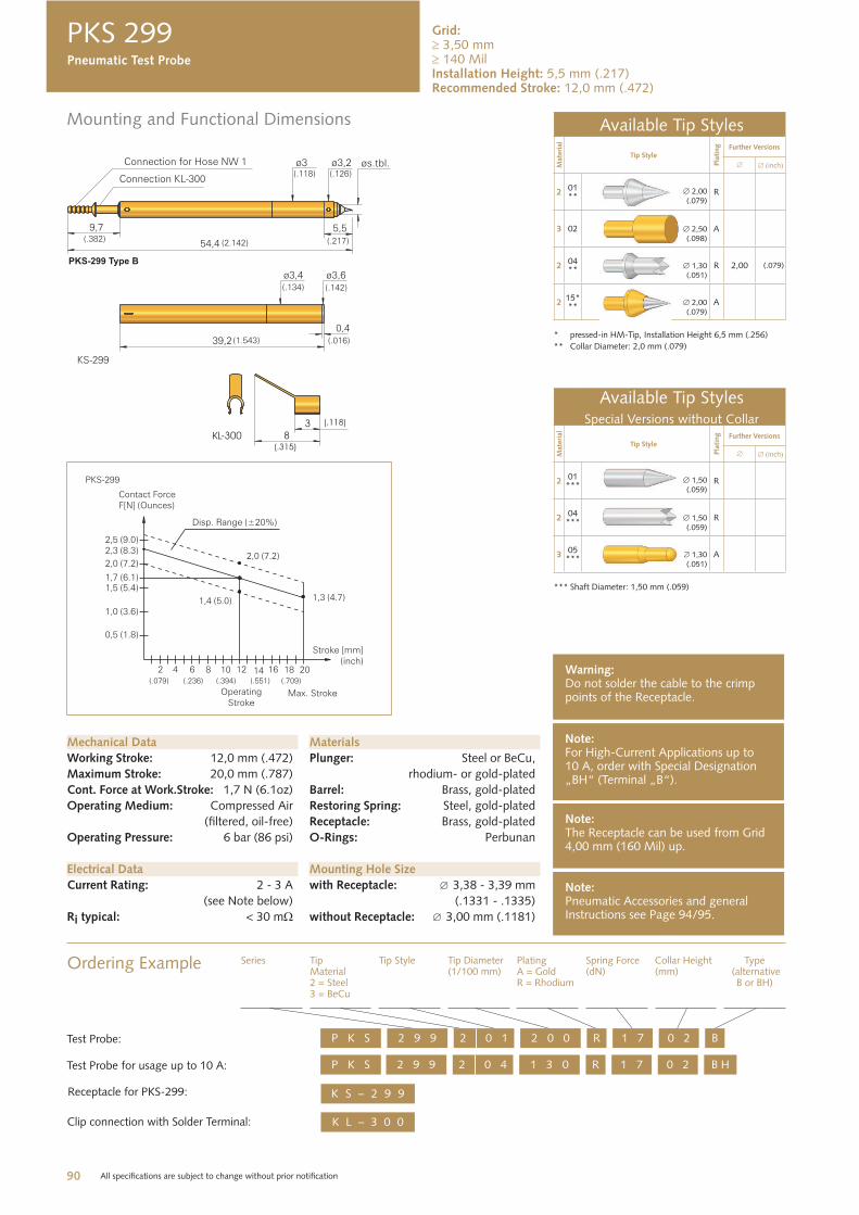
PKS 299
Available Tip Styles
Mate
rial
Tip Style
Pla
ting Further Versions
inch
201**
2,00(.079)
R
3 02 2,50(.098)
A
204** 1,30
(.051)R 2,00 (.079)
215*** 2,00
(.079)A
* pressed-in HM-Tip, Installation Height 6,5 mm (.256)
** Collar Diameter: 2,0 mm (.079)
Available Tip StylesSpecial Versions without Collar
Mat
eria
l
Tip Style
Pla
ting Further Versions
inch
201***
1,50(.059)
R
204
*** 1,50(.059)
R
305
*** 1,30(.051)
A
*** Shaft Diameter: 1,50 mm (.059)
Mechanical Data
Working Stroke: 12,0 mm (.472)
Maximum Stroke: 20,0 mm (.787)
Cont. Force at Work.Stroke: 1,7 N (6.1oz)
Operating Medium: Compressed Air
(filtered, oil-free)
Operating Pressure: 6 bar (86 psi)
Electrical Data
Current Rating: 2 - 3 A
(see Note below)
Ri typical: < 30 m
Mounting Hole Size
with Receptacle: 3,38 - 3,39 mm
(.1331 - .1335)
without Receptacle: 3,00 mm (.1181)
Materials
Plunger: Steel or BeCu,
rhodium- or gold-plated
Barrel: Brass, gold-plated
Restoring Spring: Steel, gold-plated
Receptacle: Brass, gold-plated
O-Rings: Perbunan
Note:For High-Current Applications up to 10 A, order with Special Designation „BH“ (Terminal „B“).
Ordering Example Series TipMaterial2 = Steel3 = BeCu
Tip Style Tip Diameter(1/100 mm)
PlatingA = GoldR = Rhodium
Spring Force(dN)
Collar Height(mm)
Type (alternative
B or BH)
2 9 9P K S 2 0 1 2 0 0 R B1 7 0 2Test Probe:
Note:The Receptacle can be used from Grid 4,00 mm (160 Mil) up.
Note:Pneumatic Accessories and general Instructions see Page 94/95.
Warning:Do not solder the cable to the crimp points of the Receptacle.
K L – 3 0 0 Clip connection with Solder Terminal:
K S – 2 9 9 Receptacle for PKS-299:
2 9 9P K S 2 0 4 1 3 0 R B H1 7 0 2Test Probe for usage up to 10 A:
Pneumatic Test Probe
Grid: 3,50 mm 140 Mil
Installation Height: 5,5 mm (.217)Recommended Stroke: 12,0 mm (.472)
91 All specifications are subject to change without prior notification
Mounting and Functional Dimensions
PK
S /
PSK
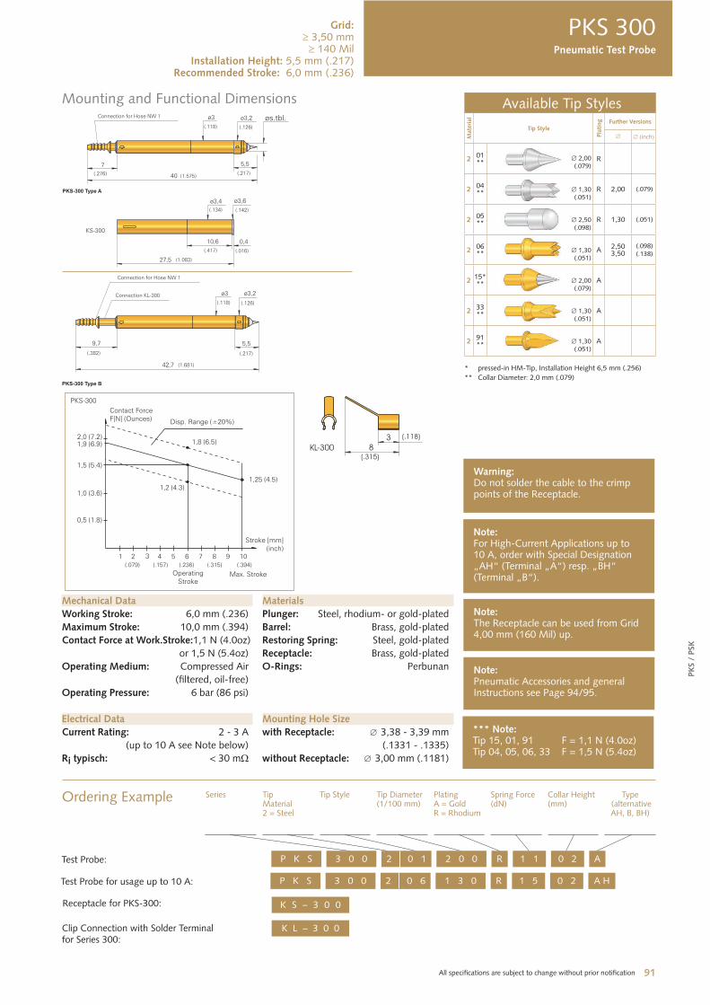
PKS 300
Available Tip Styles
Mate
rial
Tip Style
Pla
ting Further Versions
inch
201**
2,00 (.079)
R
204** 1,30
(.051)R 2,00 (.079)
205** 2,50
(.098) R 1,30 (.051)
206** 1,30
(.051) A 2,50
3,50(.098)(.138)
215*** 2,00
(.079) A
233** 1,30
(.051)A
291** 1,30
(.051) A
* pressed-in HM-Tip, Installation Height 6,5 mm (.256)
** Collar Diameter: 2,0 mm (.079)
Mechanical Data
Working Stroke: 6,0 mm (.236)
Maximum Stroke: 10,0 mm (.394)
Contact Force at Work.Stroke: 1,1 N (4.0oz)
or 1,5 N (5.4oz)
Operating Medium: Compressed Air
(filtered, oil-free)
Operating Pressure: 6 bar (86 psi)
Electrical Data
Current Rating: 2 - 3 A
(up to 10 A see Note below)
Ri typisch: < 30 m
Mounting Hole Size
with Receptacle: 3,38 - 3,39 mm
(.1331 - .1335)
without Receptacle: 3,00 mm (.1181)
Materials
Plunger: Steel, rhodium- or gold-plated
Barrel: Brass, gold-plated
Restoring Spring: Steel, gold-plated
Receptacle: Brass, gold-plated
O-Rings: Perbunan
Note:For High-Current Applications up to 10 A, order with Special Designation „AH“ (Terminal „A“) resp. „BH“ (Terminal „B“).
Ordering Example Series TipMaterial2 = Steel
Tip Style Tip Diameter(1/100 mm)
PlatingA = GoldR = Rhodium
Spring Force(dN)
Collar Height(mm)
Type (alternative AH, B, BH)
3 0 0P K S 2 0 1 2 0 0 R A1 1 0 2Test Probe:
Note:The Receptacle can be used from Grid 4,00 mm (160 Mil) up.
Note:Pneumatic Accessories and general Instructions see Page 94/95.
Warning:Do not solder the cable to the crimp points of the Receptacle.
K L – 3 0 0 Clip Connection with Solder Terminalfor Series 300:
K S – 3 0 0 Receptacle for PKS-300:
3 0 0P K S 2 0 6 1 3 0 R A H1 5 0 2Test Probe for usage up to 10 A:
*** Note:Tip 15, 01, 91 F = 1,1 N (4.0oz)Tip 04, 05, 06, 33 F = 1,5 N (5.4oz)
Pneumatic Test Probe
Grid: 3,50 mm
140 MilInstallation Height: 5,5 mm (.217)
Recommended Stroke: 6,0 mm (.236)
92 All specifications are subject to change without prior notification
Mounting and Functional Dimensions
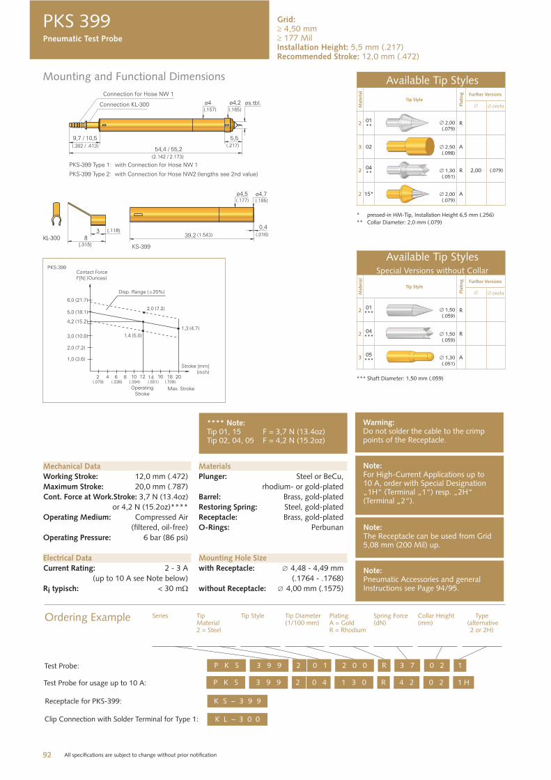
PKS 399
Available Tip Styles
Mate
rial
Tip Style
Pla
ting Further Versions
inch
201**
2,00(.079)
R
3 02 2,50(.098)
A
204** 1,30
(.051)R 2,00 (.079)
2 15* 2,00(.079)
A
* pressed-in HM-Tip, Installation Height 6,5 mm (.256)
** Collar Diameter: 2,0 mm (.079)
Available Tip StylesSpecial Versions without Collar
Mat
eria
l
Tip Style
Pla
ting Further Versions
inch
201
*** 1,50
(.059)R
204
*** 1,50(.059)
R
305
*** 1,30(.051)
A
*** Shaft Diameter: 1,50 mm (.059)
Mechanical Data
Working Stroke: 12,0 mm (.472)
Maximum Stroke: 20,0 mm (.787)
Cont. Force at Work.Stroke: 3,7 N (13.4oz)
or 4,2 N (15.2oz)****
Operating Medium: Compressed Air
(filtered, oil-free)
Operating Pressure: 6 bar (86 psi)
Electrical Data
Current Rating: 2 - 3 A
(up to 10 A see Note below)
Ri typisch: < 30 m
Mounting Hole Size
with Receptacle: 4,48 - 4,49 mm
(.1764 - .1768)
without Receptacle: 4,00 mm (.1575)
Materials
Plunger: Steel or BeCu,
rhodium- or gold-plated
Barrel: Brass, gold-plated
Restoring Spring: Steel, gold-plated
Receptacle: Brass, gold-plated
O-Rings: Perbunan
Note:For High-Current Applications up to 10 A, order with Special Designation „1H“ (Terminal „1“) resp. „2H“ (Terminal „2“).
Ordering Example
3 9 9P K S 2 0 1 2 0 0 R 13 7 0 2Test Probe:
Note:The Receptacle can be used from Grid 5,08 mm (200 Mil) up.
Note:Pneumatic Accessories and general Instructions see Page 94/95.
Warning:Do not solder the cable to the crimp points of the Receptacle.
K L – 3 0 0 Clip Connection with Solder Terminal for Type 1:
K S – 3 9 9 Receptacle for PKS-399:
3 9 9P K S 2 0 4 1 3 0 R 1 H4 2 0 2Test Probe for usage up to 10 A:
**** Note:Tip 01, 15 F = 3,7 N (13.4oz)Tip 02, 04, 05 F = 4,2 N (15.2oz)
Pneumatic Test Probe
Grid: 4,50 mm 177 Mil
Installation Height: 5,5 mm (.217)Recommended Stroke: 12,0 mm (.472)
Series TipMaterial2 = Steel
Tip Style Tip Diameter(1/100 mm)
PlatingA = GoldR = Rhodium
Spring Force(dN)
Collar Height(mm)
Type (alternative
2 or 2H)
93 All specifications are subject to change without prior notification
Mounting and Functional Dimensions
PK
S /
PSK
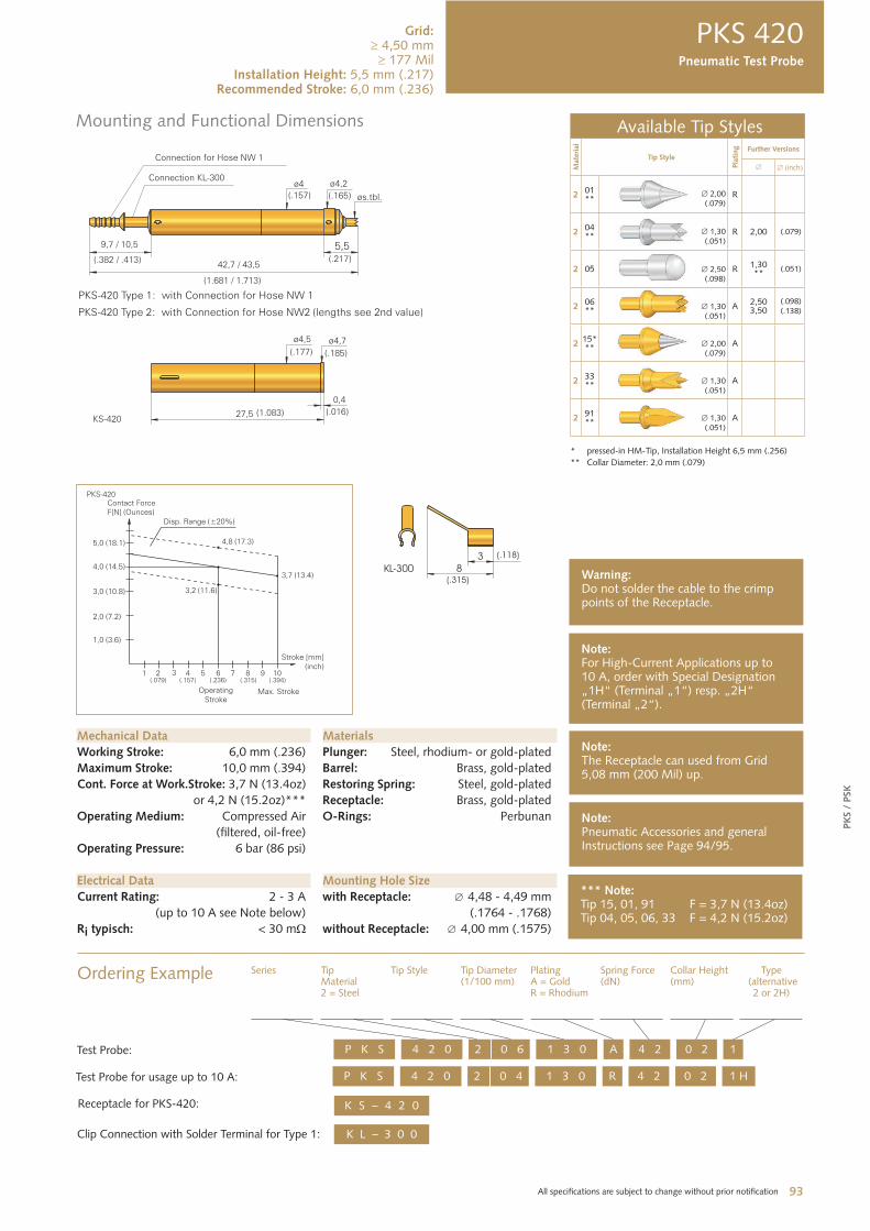
PKS 420
Available Tip Styles
Mate
rial
Tip Style
Pla
ting Further Versions
inch
201**
2,00(.079)
R
204**
1,30 (.051)
R 2,00 (.079)
2 05 2,50(.098)
R 1,30 **
(.051)
206** 1,30
(.051) A 2,50
3,50(.098)(.138)
215*** 2,00
(.079) A
233** 1,30
(.051) A
291** 1,30
(.051) A
* pressed-in HM-Tip, Installation Height 6,5 mm (.256)
** Collar Diameter: 2,0 mm (.079)
Mechanical Data
Working Stroke: 6,0 mm (.236)
Maximum Stroke: 10,0 mm (.394)
Cont. Force at Work.Stroke: 3,7 N (13.4oz)
or 4,2 N (15.2oz)***
Operating Medium: Compressed Air
(filtered, oil-free)
Operating Pressure: 6 bar (86 psi)
Electrical Data
Current Rating: 2 - 3 A
(up to 10 A see Note below)
Ri typisch: < 30 m
Mounting Hole Size
with Receptacle: 4,48 - 4,49 mm
(.1764 - .1768)
without Receptacle: 4,00 mm (.1575)
Materials
Plunger: Steel, rhodium- or gold-plated
Barrel: Brass, gold-plated
Restoring Spring: Steel, gold-plated
Receptacle: Brass, gold-plated
O-Rings: Perbunan
Note:For High-Current Applications up to 10 A, order with Special Designation „1H“ (Terminal „1“) resp. „2H“ (Terminal „2“).
Ordering Example
4 2 0P K S 2 0 6 1 3 0 A 14 2 0 2Test Probe:
Note:The Receptacle can used from Grid 5,08 mm (200 Mil) up.
Note:Pneumatic Accessories and general Instructions see Page 94/95.
Warning:Do not solder the cable to the crimp points of the Receptacle.
K L – 3 0 0 Clip Connection with Solder Terminal for Type 1:
K S – 4 2 0 Receptacle for PKS-420:
4 2 0P K S 2 0 4 1 3 0 R 1 H4 2 0 2Test Probe for usage up to 10 A:
*** Note:Tip 15, 01, 91 F = 3,7 N (13.4oz)Tip 04, 05, 06, 33 F = 4,2 N (15.2oz)
Grid: 4,50 mm
177 MilInstallation Height: 5,5 mm (.217)
Recommended Stroke: 6,0 mm (.236)
Pneumatic Test Probe
Series TipMaterial2 = Steel
Tip Style Tip Diameter(1/100 mm)
PlatingA = GoldR = Rhodium
Spring Force(dN)
Collar Height(mm)
Type (alternative
2 or 2H)
94 All specifications are subject to change without prior notification
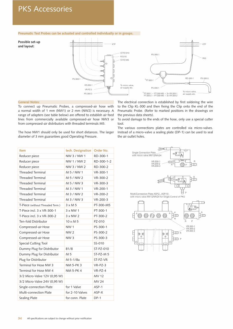
PKS Accessories
Pneumatic Test Probes can be actuated and controlled individually or in groups.
Possible set-up
and layout:
General Notes:
To connect up Pneumatic Probes, a compressed-air hose with
a normal width of 1 mm (NW1) or 2 mm (NW2) is necessary. A
range of adapters (see table below) are offered to establish air feed
lines from commercially available compressed-air hose NW3 or
from compressed-air distributors with threaded terminals M5.
The hose NW1 should only be used for short distances. The larger
diameter of 3 mm guarantees good Operating Pressure.
The electrical connection is established by first soldering the wire
to the Clip KL-300 and then fixing the Clip onto the end of the
Pneumatic Probe. (Refer to marked positions in the drawings on
the previous data sheets).
To avoid damage to the ends of the hose, only use a special cutter
tool.
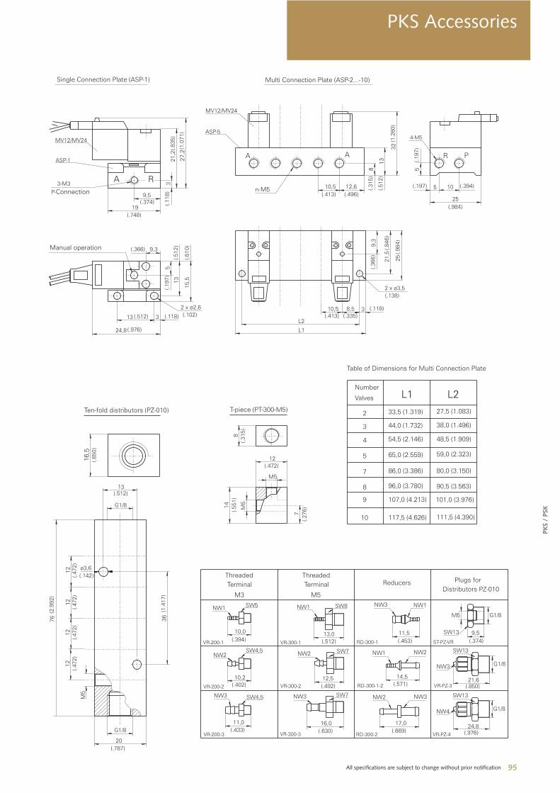
The various connections plates are controlled via micro-valves.
Instead of a micro-valve a sealing plate (DP-1) can be used to seal
the air outlet holes.
Item tech. Designation Order No.
Reducer piece NW 3 / NW 1 RD-300-1
Reducer piece NW 1 / NW 2 RD-300-1-2
Reducer piece NW 3 / NW 2 RD-300-2
Threaded Terminal M 5 / NW 1 VR-300-1
Threaded Terminal M 5 / NW 2 VR-300-2
Threaded Terminal M 5 / NW 3 VR-300-3
Threaded Terminal M 3 / NW 1 VR-200-1
Threaded Terminal M 3 / NW 2 VR-200-2
Threaded Terminal M 3 / NW 3 VR-200-3
T-Piece (without Threaded Term.) 3 x M 5 PT-300-M5
T-Piece incl. 3 x VR-300-1 3 x NW 1 PT-300-1
T-Piece incl. 3 x VR-300-2 3 x NW 2 PT-300-2
Ten-fold Distributor 10 x M 5 PZ-010
Compressed-air Hose NW 1 PS-300-1
Compressed-air Hose NW 2 PS-300-2
Compressed-air Hose NW 3 PS-300-3
Special Cutting Tool SS-010
Dummy Plug for Distributor B1/8 ST-PZ-010
Dummy Plug for Distributor M 5 ST-PZ-M 5
Plug for Distributor M 5-1/8a ST-PZ-VR
Terminal for Hose NW 3 NM 5-PK 3 VR-PZ-3
Terminal for Hose NW 4 NM 5-PK 4 VR-PZ-4
3/2 Micro-Valve 12V (0,95 W) MV 12
3/2 Micro-Valve 24V (0,95 W) MV 24
Single-connection Plate for 1 Valve ASP-1
Multi-connection Plate for 2-10 Valves ASP-X
Sealing Plate for conn. Plate DP-1
95 All specifications are subject to change without prior notification
PK
S /
PSK
PKS Accessories


![Ingun Test Probes Catalog 2013-14[1]](https://img.pdfslide.net/doc/110x75/55cf96c8550346d0338dc1ad/ingun-test-probes-catalog-2013-141.jpg)