Embed Size (px)
Citation preview
An Approved Continuing Education Provider
PDHonline Course M517 (8 PDH)
_____________________________________________________
Pneumatics & Compressed Air
Automation Guidebook – Part 1 Instructor: Jurandir Primo, PE
2014
PDH Online | PDH Center
5272 Meadow Estates Drive
Fairfax, VA 22030-6658
Phone & Fax: 703-988-0088
www.PDHonline.org
www.PDHcenter.com
www.PDHcenter.com PDHonline Course M517 www.PDHonline.org
©2014 Jurandir Primo Page 1 of 103
PNEUMATICS & COMPRESSED AIR AUTOMATION GUIDEBOOK – PART 1
CONTENTS:
INTRODUCTION
AIR PROPERTIES
PRESSURE
TEMPERATURE
DENSITY AND ALTITUDE
THE COMPRESSED AIR CIRCUIT
COMPRESSOR & COMPRESSED AIR SYSTEMS
PNEUMATIC VALVES
CYLINDERS AND ACTUATORS
PNEUMATIC DIAGRAMS
BASIC ELECTRO-PNEUMATIC CONTROL
PNEUMATICS – SOFTWARE SIMULATIONS
PARTS OF PNEUMATIC SYSTEMS
PNEUMATICS – BASIC SYSTEM DESCRIPTION
www.PDHcenter.com PDHonline Course M517 www.PDHonline.org
©2014 Jurandir Primo Page 2 of 103
INTRODUCTION:
Pneumatics comes from the Greek word “pneuma”, which means “breath or wind”. It is basically
the use of pressurized air or gas that helps in performing a certain work to produce mechanical
motion or to cause some process control. Pneumatic systems are used extensively in industry
and factories, commonly installed with compressed air or compressed inert gases centrally located,
electrically powered, which powers cylinders and other pneumatic devices using solenoid valves,
control valves, diaphragms, and several types of actuators.
Pneumatics is the transmission and control of forces and movements by means of compressed air
and, for considerable time is used in carrying out complex electro-mechanical mechanical tasks,
playing a vital and important role in automation and development of sophisticated technologies.
Fluid power is the energy transmitted and controlled by means of a pressurized fluid, either liquid
or gas. The term fluid power applies to both hydraulics and pneumatics. Hydraulics (oil or water)
use liquids under pressure, while pneumatics use compressed air or other neutral gases.
AIR PROPERTIES:
Air is the Earth's atmosphere. It is the clear gas in which living things live and breathe with indefi-
nite shape and volume, but has mass and weight; however, has no color or smell. Air creates the
atmosphere pressure. There is no air in the vacuum and cosmos.
The atmosphere of Earth is a layer of gases surrounding the planet Earth, retained by gravity. The
atmosphere protects life on Earth by absorbing ultraviolet solar radiation, warming the surface th-
rough heat retention (greenhouse effect), and reducing the extremes of temperature between day
and night (the diurnal temperature variations). Then air, is the common name given to the atmos-
pheric gases used in breathing and photosynthesis.
By volume, dry air contains 78.09% nitrogen, 20.95% oxygen, 0.93% argon, 0.039% carbon
dioxide, and small amounts of other gases. Air also contains a variable amount of water vapor, on
average around 1%. Although the air content and atmospheric pressure vary at different altitude
layers, the suitable air for survival of plants and animals currently is only known to be found in
troposphere and artificial atmospheres.
The atmosphere is within about 6.8 miles (36,000 ft) of the surface and becomes thinner and thin-
ner with increasing altitude, with no definite boundary between the atmosphere and outer space.
The Karmán line, (62 miles or 100 Km), 1.57% of Earth's radius, is often used as the border be-
tween the atmosphere and outer space.
Atmospheric effects become noticeable during atmospheric reentry of spacecraft at an altitude of
around 75 miles (120 km). The study of Earth's atmosphere is called atmospheric science or ae-
rology. Early pioneers in the field include Léon Teisserenc de Bort and Richard Assmann.
www.PDHcenter.com PDHonline Course M517 www.PDHonline.org
©2014 Jurandir Primo Page 3 of 103
Many substances may be present in the air as, aerosols in an unfiltered air sample, dust of mineral
and organic compounds, pollen and spores, sea spray and volcanic ash. Various industrial pollutan-
ts may also be present as, gases or aerosols, chlorine (elemental or in compounds), fluorine com-
pounds, elemental mercury vapor and sulfur compounds such as, hydrogen sulfide and sulfur di-
oxide (SO2), derived from natural sources and industrial air pollution.
Air pressure and density decrease with altitude in the atmosphere. However, temperature has a
more complicated profile in composition with altitude, and may stay relatively constant or even in-
crease with altitude in some regions. In this way, Earth's atmosphere can be divided (called atmos-
pheric stratification) into five main layers. From highest to lowest, these layers are:
Exosphere: >700 km (>440 miles);
Thermosphere: 80 to 700 km (50 to 440 miles);
Mesosphere: 50 to 80 km (31 to 50 miles);
Stratosphere: 12 to 50 km (7 to 31 miles);
Troposphere: 0 to 12 km (0 to 7 miles);
PRESSURE:
Pressure (P) is the force per unit area applied in a direction perpendicular to the surface of an obje-
ct. Mathematically it is P = F/A, where F is Force and A is Area. Then, atmospheric pressure is the
total weight of the air above unit area at the point where the pressure is measured. The air pressu-
re varies with location and weather. The main basic pressure units are: 101300 Pa (Pascal) =
101.3 kPa (Kilopascals) = 0.1013 mPa (Megapascal) = 1.013 bar = 1.033 kg/cm² abs = 760 mmHg
(torr) = 14.7 psia = 29.92 inches of mercury (Hg).
There are three standards available:
1. API Standard: 14.7 psia, 60°F, 0% relative humidity;
2. ASME Standard: 14.7 psia, 68°F, 36% relative humidity;
3. CAGI Standard: 14.7 psia, 60°F, 36% relative humidity;
TEMPERATURE:
Temperature decreases with altitude starting at sea level. Above 11 km, the temperature stabi-
lizes through a large vertical distance through the rest of the troposphere. The main temperature
units are:
Celsius scale (also known as centigrade) at 0°C is defined as the freezing point of water,
and the temperature at 100 °C is defined as the boiling point of water.
Fahrenheit scale at 32°F is defined as the freezing point of water, and the temperature at
212°F is defined as the boiling point of water.
www.PDHcenter.com PDHonline Course M517 www.PDHonline.org
©2014 Jurandir Primo Page 4 of 103
The relation between Celsius and Fahrenheit becomes:
F° = 1.8 C° + 32
C° = F-32
1.8
OBS.: The average temperature of the atmosphere at the surface of Earth is 14 °C (57 °F; 287 K)
or 15 °C (59 °F; 288 K) depending on the reference.
Both pneumatics and hydraulics are applications of fluid power. Pneumatics uses an easily com-
pressible gas such as air or a suitable pure gas, while hydraulics uses relatively incompressible liq-
uid media such as oil. Pneumatic applications usually use pressures of about 80 to 100 psi (550
to 690 kPa). Hydraulics applications commonly use from 1,000 to 5,000 psi (6.9 to 34.5 mPa),
but specialized applications may exceed 10,000 psi (69 mPa).
DENSITY AND ALTITUDE:
The density of air at sea level is about 1.2 kg/m³ (0.002378 slugs/ft3). Density is not meas-
ured directly but is calculated from measurements of temperature, pressure, and humidity using
the equation of state for air (a form of the ideal gas law). The atmospheric density decreases as
the altitude increases. More sophisticated models are used to predict orbital decay of satellites.
Although the concept of density altitude is commonly used to describe the effect on aircraft and
engine performance, the underlying property of interest is actually the air density. For example,
the lift of an aircraft wing, the aerodynamic drag and the thrust of a propeller blade are all directly
proportional to the air density. The down force of a racecar spoiler is also directly proportional to
the air density.
Air density is affected by the air pressure, temperature, and humidity. The density of the air
is reduced by decreased air pressure, increased temperatures, and increased moisture. A reduction
in air density reduces the engine horsepower, reduces aerodynamic lift, and reduces drag.
The altitude (or elevation) is the geometric altitude above sea level where the altimeter setting,
temperature, and dew point have been measured. The absolute air pressure is the actual air pres-
sure, not corrected for altitude, and is also called the station pressure. Relative density is the ratio
of the actual air density to the standard sea level density, expressed as a percentage.
1. Density Altitude with Relative Humidity:
The National Weather Service information shows the hourly dew point, relative humidity and
altimeter setting for US locations, in both English and Metric units. The International Standard
Atmosphere standard conditions for zero density altitude are:
www.PDHcenter.com PDHonline Course M517 www.PDHonline.org
©2014 Jurandir Primo Page 5 of 103
Altitude 0 meters (0 ft), Air Temperature 15°C (59°F), Air Pressure 1013.25 mPa (29.92 in
Hg) and Relative Humidity 0 % (0 absolute dew point). The Standard Sea Level Air Density
is 1.225 kg/m3 (0.002378 slugs/ft3). At 20 °C and 1.0 bar (101.325 kPa), dry air has
a density of 1.2041 kg/m³. At 70 °F and 14.696 psi, dry air has a density of 0.074887
lbm/ft³.
The 1976 International Standard Atmosphere is mostly described in metric SI units.
2. Air Density Calculations:
To begin to understand the calculation of air density, consider the ideal gas law. The specific gas
constant for dry air is 287.058 J/(kg·K) in SI units, and 53.35 (ft·lbf)/(lbm·°R) in United Sta-
tes customary and Imperial units.
P x V = n x R x T
Where:
P = pressure
V = volume
n = number of moles
R = gas constant
T = temperature
Density is simply the number of molecules of the ideal gas in a certain volume, in this case a molar
volume, which may be mathematically expressed as:
D = n / V
Where:
D = density
n = number of molecules
V = volume
Then, by combining the previous two equations, the expression for the density becomes:
D = P..
R x T
Where:
D = Density, kg/m3
P = Pressure, Pascal
R = Gas Constant, J/(kg°K) = 287.05 for dry air
T = Temperature, °K = (°C + 273.15)
www.PDHcenter.com PDHonline Course M517 www.PDHonline.org
©2014 Jurandir Primo Page 6 of 103
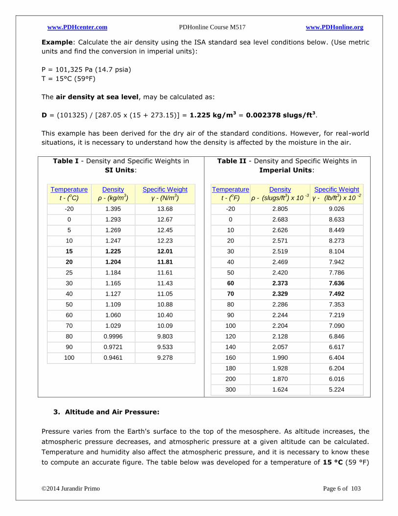
Example: Calculate the air density using the ISA standard sea level conditions below. (Use metric
units and find the conversion in imperial units):
P = 101,325 Pa (14.7 psia)
T = 15°C (59°F)
The air density at sea level, may be calculated as:
D = (101325) / [287.05 x (15 + 273.15)] = 1.225 kg/m3 = 0.002378 slugs/ft3.
This example has been derived for the dry air of the standard conditions. However, for real-world
situations, it is necessary to understand how the density is affected by the moisture in the air.
Table I - Density and Specific Weights in
SI Units:
Temperature
t - (oC)
Density
ρ - (kg/m3)
Specific Weight
γ - (N/m3)
-20 1.395 13.68
0 1.293 12.67
5 1.269 12.45
10 1.247 12.23
15 1.225 12.01
20 1.204 11.81
25 1.184 11.61
30 1.165 11.43
40 1.127 11.05
50 1.109 10.88
60 1.060 10.40
70 1.029 10.09
80 0.9996 9.803
90 0.9721 9.533
100 0.9461 9.278
Table II - Density and Specific Weights in
Imperial Units:
Temperature
t - (oF)
Density
ρ - (slugs/ft
3) x 10
-3
Specific Weight
γ - (lb/ft
3) x 10
-2
-20 2.805 9.026
0 2.683 8.633
10 2.626 8.449
20 2.571 8.273
30 2.519 8.104
40 2.469 7.942
50 2.420 7.786
60 2.373 7.636
70 2.329 7.492
80 2.286 7.353
90 2.244 7.219
100 2.204 7.090
120 2.128 6.846
140 2.057 6.617
160 1.990 6.404
180 1.928 6.204
200 1.870 6.016
300 1.624 5.224
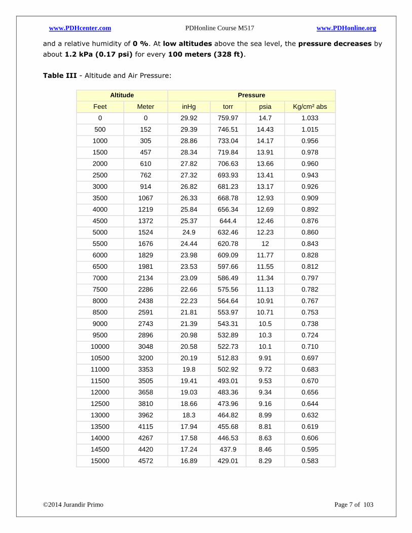
3. Altitude and Air Pressure:
Pressure varies from the Earth's surface to the top of the mesosphere. As altitude increases, the
atmospheric pressure decreases, and atmospheric pressure at a given altitude can be calculated.
Temperature and humidity also affect the atmospheric pressure, and it is necessary to know these
to compute an accurate figure. The table below was developed for a temperature of 15 °C (59 °F)
www.PDHcenter.com PDHonline Course M517 www.PDHonline.org
©2014 Jurandir Primo Page 7 of 103
and a relative humidity of 0 %. At low altitudes above the sea level, the pressure decreases by
about 1.2 kPa (0.17 psi) for every 100 meters (328 ft).
Table III - Altitude and Air Pressure:
Altitude Pressure
Feet Meter inHg torr psia Kg/cm² abs
0 0 29.92 759.97 14.7 1.033
500 152 29.39 746.51 14.43 1.015
1000 305 28.86 733.04 14.17 0.956
1500 457 28.34 719.84 13.91 0.978
2000 610 27.82 706.63 13.66 0.960
2500 762 27.32 693.93 13.41 0.943
3000 914 26.82 681.23 13.17 0.926
3500 1067 26.33 668.78 12.93 0.909
4000 1219 25.84 656.34 12.69 0.892
4500 1372 25.37 644.4 12.46 0.876
5000 1524 24.9 632.46 12.23 0.860
5500 1676 24.44 620.78 12 0.843
6000 1829 23.98 609.09 11.77 0.828
6500 1981 23.53 597.66 11.55 0.812
7000 2134 23.09 586.49 11.34 0.797
7500 2286 22.66 575.56 11.13 0.782
8000 2438 22.23 564.64 10.91 0.767
8500 2591 21.81 553.97 10.71 0.753
9000 2743 21.39 543.31 10.5 0.738
9500 2896 20.98 532.89 10.3 0.724
10000 3048 20.58 522.73 10.1 0.710
10500 3200 20.19 512.83 9.91 0.697
11000 3353 19.8 502.92 9.72 0.683
11500 3505 19.41 493.01 9.53 0.670
12000 3658 19.03 483.36 9.34 0.656
12500 3810 18.66 473.96 9.16 0.644
13000 3962 18.3 464.82 8.99 0.632
13500 4115 17.94 455.68 8.81 0.619
14000 4267 17.58 446.53 8.63 0.606
14500 4420 17.24 437.9 8.46 0.595
15000 4572 16.89 429.01 8.29 0.583
www.PDHcenter.com PDHonline Course M517 www.PDHonline.org
©2014 Jurandir Primo Page 8 of 103
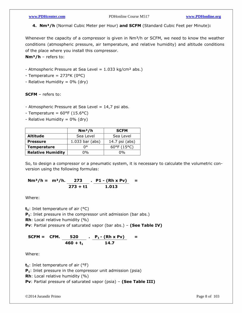
4. Nm³/h (Normal Cubic Meter per Hour) and SCFM (Standard Cubic Feet per Minute):
Whenever the capacity of a compressor is given in Nm³/h or SCFM, we need to know the weather
conditions (atmospheric pressure, air temperature, and relative humidity) and altitude conditions
of the place where you install this compressor.
Nm³/h – refers to:
- Atmospheric Pressure at Sea Level = 1.033 kg/cm² abs.)
- Temperature = 273°K (0ºC)
- Relative Humidity = 0% (dry)
SCFM – refers to:
- Atmospheric Pressure at Sea Level = 14,7 psi abs.
- Temperature = 60°F (15.6°C)
- Relative Humidity = 0% (dry)
Nm³/h SCFM
Altitude Sea Level Sea Level
Pressure 1.033 bar (abs) 14.7 psi (abs)
Temperature 0° 60°F (15°C)
Relative Humidity 0% 0%
So, to design a compressor or a pneumatic system, it is necessary to calculate the volumetric con-
version using the following formulas:
Nm³/h = m³/h. 273 . P1 - (Rh x Pv) =
273 + t1
1.013
Where:
t1: Inlet temperature of air (°C)
P1: Inlet pressure in the compressor unit admission (bar abs.)
Rh: Local relative humidity (%)
Pv: Partial pressure of saturated vapor (bar abs.) – (See Table IV)
SCFM = CFM. 520 . P1 - (Rh x Pv) =
460 + t1
14.7
Where:
t1: Inlet temperature of air (°F)
P1: Inlet pressure in the compressor unit admission (psia)
Rh: Local relative humidity (%)
Pv: Partial pressure of saturated vapor (psia) – (See Table III)
www.PDHcenter.com PDHonline Course M517 www.PDHonline.org
©2014 Jurandir Primo Page 9 of 103
Conversion from SCFM to Nm³/h:
Nm³/h = 1.6077 x SCFM
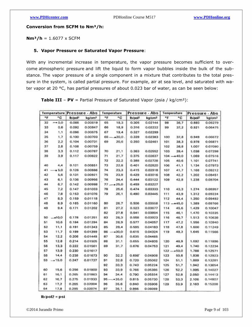
5. Vapor Pressure or Saturated Vapor Pressure:
With any incremental increase in temperature, the vapor pressure becomes sufficient to over-
come atmospheric pressure and lift the liquid to form vapor bubbles inside the bulk of the sub-
stance. The vapor pressure of a single component in a mixture that contributes to the total pres-
sure in the system, is called partial pressure. For example, air at sea level, and saturated with wa-
ter vapor at 20 °C, has partial pressures of about 0.023 bar of water, as can be seen below:
Table III – PV = Partial Pressure of Saturated Vapor (psia / kg/cm²):
www.PDHcenter.com PDHonline Course M517 www.PDHonline.org
©2014 Jurandir Primo Page 10 of 103
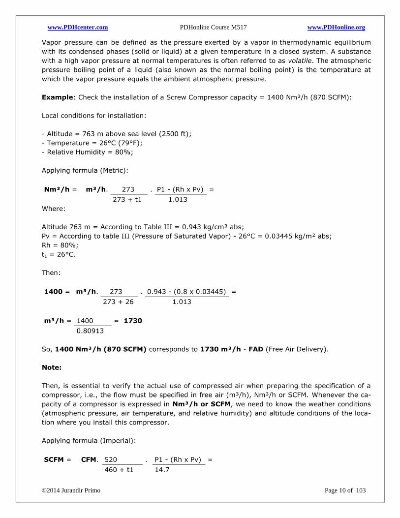
Vapor pressure can be defined as the pressure exerted by a vapor in thermodynamic equilibrium
with its condensed phases (solid or liquid) at a given temperature in a closed system. A substance
with a high vapor pressure at normal temperatures is often referred to as volatile. The atmospheric
pressure boiling point of a liquid (also known as the normal boiling point) is the temperature at
which the vapor pressure equals the ambient atmospheric pressure.
Example: Check the installation of a Screw Compressor capacity = 1400 Nm³/h (870 SCFM):
Local conditions for installation:
- Altitude = 763 m above sea level (2500 ft);
- Temperature = 26°C (79°F);
- Relative Humidity = 80%;
Applying formula (Metric):
Nm³/h = m³/h. 273 . P1 - (Rh x Pv) =
273 + t1
1.013
Where:
Altitude 763 m = According to Table III = 0.943 kg/cm³ abs;
Pv = According to table III (Pressure of Saturated Vapor) - 26°C = 0.03445 kg/m² abs;
Rh = 80%;
t1 = 26°C.
Then:
1400 = m³/h. 273 . 0.943 - (0.8 x 0.03445) =
273 + 26
1.013
m³/h = 1400 = 1730
0.80913
So, 1400 Nm³/h (870 SCFM) corresponds to 1730 m³/h - FAD (Free Air Delivery).
Note:
Then, is essential to verify the actual use of compressed air when preparing the specification of a
compressor, i.e., the flow must be specified in free air (m³/h), Nm³/h or SCFM. Whenever the ca-
pacity of a compressor is expressed in Nm³/h or SCFM, we need to know the weather conditions
(atmospheric pressure, air temperature, and relative humidity) and altitude conditions of the loca-
tion where you install this compressor.
Applying formula (Imperial):
SCFM = CFM. 520 . P1 - (Rh x Pv) =
460 + t1
14.7
www.PDHcenter.com PDHonline Course M517 www.PDHonline.org
©2014 Jurandir Primo Page 11 of 103
Where:
Altitude 2500 ft = According to table P1 = 13.41 psia;
Pv = According to table III (Pressure of Saturated Vapor) - 79°F = 0.490 psia;
Rh = 80%;
t1 = 79°F;
870 = CFM. 520 . 13.41 - (0.8 x 0.490) =
460 + 79
14.7
870 = CFM x 0.96474 x 0.8856 = 1018 CFM
Then, we have 870 SCFM corresponding to 1018 CFM - FAD (Free Air Delivery).
Conversion from SCFM to CFM:
870 = CFM x 0.96474 x 0.8856 = 1018 CFM
6. Imperial Units References:
CFM (Cubic Feet per Minute): is the imperial method of describing the volume flow rate
of compressed air. It must be defined further to take account of pressure, temperature, and
relative humidity.
SCFM (Standard CFM): is the flow in CFM measured at some reference point but con-
verted back to standard or normal air conditions (Standard Reference Atmosphere) 14.7
psia, 60°F and 0% relative humidity.
ICFM (Inlet CFM): rating is used to measure air flow in CFM (ft³/min) as it enters the air
compressor intake.
ACFM (Actual CFM): rating is used to measure air flow in CFM at some reference point at
local conditions. This is the actual volume flow rate in the pipework after the compressor.
FAD (Free Air Delivery): is the actual quantity of compressed air at the discharge of the
compressor. The units for FAD are measured according the ambient inlet standard condi-
tions (ISO 1217 - 1 bar abs and 20°C).
7. Europe Units References:
ANR (Atmosphere Normale de Reference) is quantity of air at conditions 1.013 bar abso-
lute (1.033 kg/cm² abs), 20o C and 65% RH (Relative Humidity).
Nl/min (Normal liter/min) is the flow in l/min measured at some reference point but con-
verted to standard or normal air conditions 1.013 bar absolute (1.033 kg/cm² abs), 0oC,
and 0% RH (Relative Humidity).
ISO 1217 Standard reference for ambient conditions - temperature 20oC, pressure 1.0 bar
abs, relative humidity 0%, cooling air/water 20oC and working pressure at outlet 7.0 bar
absolute.
www.PDHcenter.com PDHonline Course M517 www.PDHonline.org
©2014 Jurandir Primo Page 12 of 103
8. The Barometer
Evangelista Torricelli was born in 1608 in Faenza, Italy and died in 1647 in Florence, Italy. Evange-
lista Torricelli became the first scientist to create a sustained vacuum and to discover the principle
of a barometer, invented by Torricelli in 1643. It was Galileo that suggested using mercury in
his vacuum experiments. It works because the air applies pressure with its weight.
Torricelli noted that the opening of a glass tube filled with mercury, the atmospheric pressure
would affect the weight of the column of mercury in the tube. The higher the air pressure, the
longer is the column of mercury. Thus, the pressure can be calculated by multiplying the height of
the column of mercury by mercury density and the acceleration of gravity.
At sea level, atmospheric pressure is about 15 psi, 29.9 in.Hg (inches of mercury) or 760 mmHg.
This is equivalent to 101.3 kPa, the unit of pressure used by meteorologists, in addition to the mil-
libars. There are two types of barometers in current use: the mercury barometers and the aneroid
barometers (metallic).
In 1843, the French scientist Lucien Vidie invented the aneroid barometer. The aneroid barometer
"registers the change in the shape of an evacuated metal cell to measure variations on the atmos-
pheric pressure." Aneroid means fluidless, no liquids are used, the metal cell is usually made of
phosphor bronze or beryllium copper.
An altimeter is an aneroid barometer that measures altitude. Meteorologists, geologists, and land
surveyors use altimeters that measure the altitude with respect to sea level pressure. A baro-
graph is an aneroid barometer that gives a continuous reading of atmospheric pressures on a
graph paper.
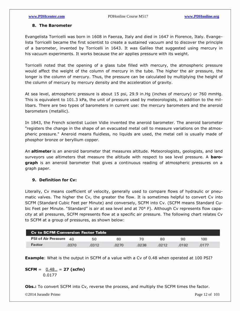
9. Definition for Cv:
Literally, Cv means coefficient of velocity, generally used to compare flows of hydraulic or pneu-
matic valves. The higher the Cv, the greater the flow. It is sometimes helpful to convert Cv into
SCFM (Standard Cubic Feet per Minute) and conversely, SCFM into Cv. (SCFM means Standard Cu-
bic Feet per Minute. “Standard” is air at sea level and at 70° F). Although Cv represents flow capa-
city at all pressures, SCFM represents flow at a specific air pressure. The following chart relates Cv
to SCFM at a group of pressures, as shown below:
Example: What is the output in SCFM of a value with a Cv of 0.48 when operated at 100 PSI?
SCFM = 0.48.. = 27 (scfm)
0.0177
Obs.: To convert SCFM into Cv, reverse the process, and multiply the SCFM times the factor.
www.PDHcenter.com PDHonline Course M517 www.PDHonline.org
©2014 Jurandir Primo Page 13 of 103
THE COMPRESSED AIR CIRCUIT:
The air is taken into the compressor and work is done when the air is compressed, normally by a
factor of 8:1 or 10:1, depending on the specification and performance of the compressor and com-
monly stored in a reservoir or tank receiver always designed according to ASME VIII rules and
specifications.
Air compressors are used to produce the compressed air for the systems through a required vo-
lume and pressure. As a rule, pneumatic components are designed for a maximum operating pres-
sure of 8 - 10 bar (~120 – 150 psi), but in practice it is recommended to operate between at 6.5
and 7.0 bar (~95 – 100 psi), for economic, safe use, and due to the pressure losses in valves or
the distribution systems.
The discharge air from the compressors can be at 250°F and reach up to 350°F (for centrifugal, oil-
free rotary screw and reciprocating types), or from 200 to 220°F (for lubricant-cooled rotary screw
compressors), so the pipe must be able to withstand those temperatures. The aftercooler drops the
temperature to 100°, but consideration must be given if the aftercooler may fail.
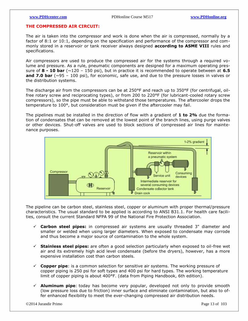
The pipelines must be installed in the direction of flow with a gradient of 1 to 2% due the forma-
tion of condensates that can be removed at the lowest point of the branch lines, using purge valves
or other devices. Shut-off valves are used to block sections of compressed air lines for mainte-
nance purposes.
The pipeline can be carbon steel, stainless steel, copper or aluminum with proper thermal/pressure
characteristics. The usual standard to be applied is according to ANSI B31.1. For health care facili-
ties, consult the current Standard NFPA 99 of the National Fire Protection Association.
Carbon steel pipes: in compressed air systems are usually threaded 3" diameter and
smaller or welded when using larger diameters. When exposed to condensate may corrode
and thus become a major source of contamination to the whole system.
Stainless steel pipes: are often a good selection particularly when exposed to oil-free wet
air and its extremely high acid level condensate (before the dryers), however, has a more
expensive installation cost than carbon steels.
Copper pipe: is a common selection for sensitive air systems. The working pressure of
copper piping is 250 psi for soft types and 400 psi for hard types. The working temperature
limit of copper piping is about 400°F. (data from Piping Handbook, 6th edition).
Aluminum pipe: today has become very popular, developed not only to provide smooth
(low pressure loss due to friction) inner surface and eliminate contamination, but also to of-
fer enhanced flexibility to meet the ever-changing compressed air distribution needs.
www.PDHcenter.com PDHonline Course M517 www.PDHonline.org
©2014 Jurandir Primo Page 14 of 103
Thus, the basic objective of the interconnecting piping is to deliver the air to the filters and
dryers, and then to production of the air distribution system with little or no pressure loss, and
certainly with little or no contamination. Compressed air-generated condensate tends to be acidic,
then, also corrosive.
Air preparation: Provide a quality air supply to the plant systems that will promote reliable
operation and increased efficiency, through the removal of particles or contamination from the air
stream such as water and the control of pressure to minimize energy. The most common equi-
pment types for air preparation are:
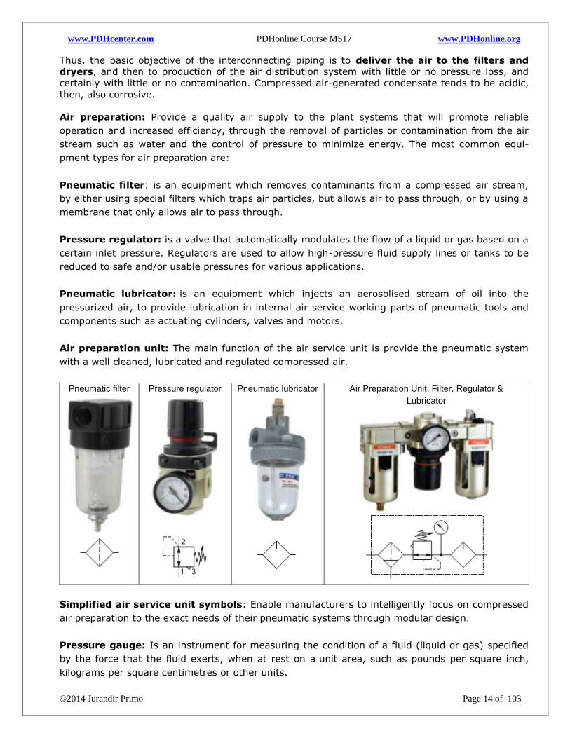
Pneumatic filter: is an equipment which removes contaminants from a compressed air stream,
by either using special filters which traps air particles, but allows air to pass through, or by using a
membrane that only allows air to pass through.
Pressure regulator: is a valve that automatically modulates the flow of a liquid or gas based on a
certain inlet pressure. Regulators are used to allow high-pressure fluid supply lines or tanks to be
reduced to safe and/or usable pressures for various applications.
Pneumatic lubricator: is an equipment which injects an aerosolised stream of oil into the
pressurized air, to provide lubrication in internal air service working parts of pneumatic tools and
components such as actuating cylinders, valves and motors.
Air preparation unit: The main function of the air service unit is provide the pneumatic system
with a well cleaned, lubricated and regulated compressed air.
Pneumatic filter
Pressure regulator
Pneumatic lubricator
Air Preparation Unit: Filter, Regulator &
Lubricator
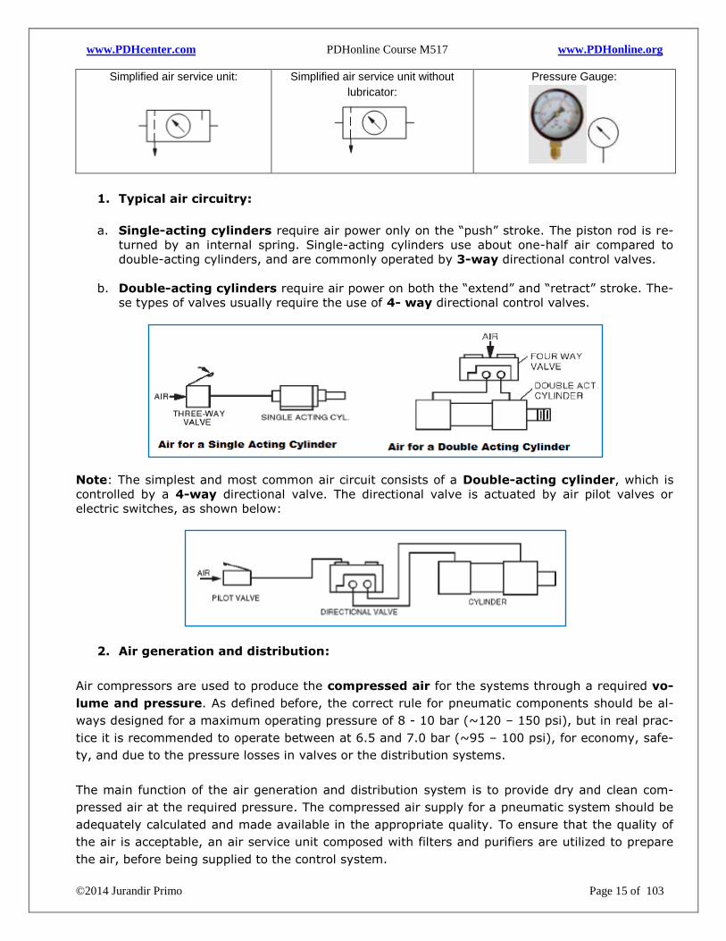
Simplified air service unit symbols: Enable manufacturers to intelligently focus on compressed
air preparation to the exact needs of their pneumatic systems through modular design.
Pressure gauge: Is an instrument for measuring the condition of a fluid (liquid or gas) specified
by the force that the fluid exerts, when at rest on a unit area, such as pounds per square inch,
kilograms per square centimetres or other units.
www.PDHcenter.com PDHonline Course M517 www.PDHonline.org
©2014 Jurandir Primo Page 15 of 103
Simplified air service unit:
Simplified air service unit without
lubricator:
Pressure Gauge:
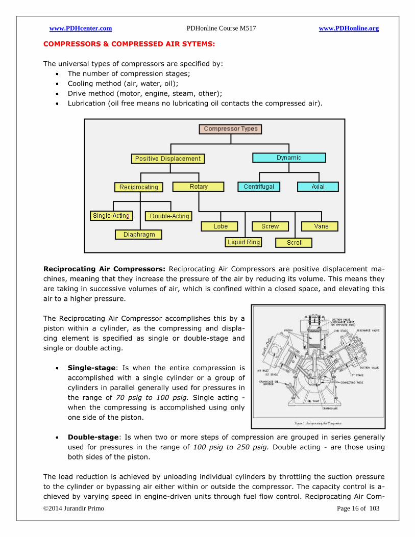
1. Typical air circuitry:
a. Single-acting cylinders require air power only on the “push” stroke. The piston rod is re-
turned by an internal spring. Single-acting cylinders use about one-half air compared to
double-acting cylinders, and are commonly operated by 3-way directional control valves.
b. Double-acting cylinders require air power on both the “extend” and “retract” stroke. The-
se types of valves usually require the use of 4- way directional control valves.
Note: The simplest and most common air circuit consists of a Double-acting cylinder, which is
controlled by a 4-way directional valve. The directional valve is actuated by air pilot valves or
electric switches, as shown below:
2. Air generation and distribution:
Air compressors are used to produce the compressed air for the systems through a required vo-
lume and pressure. As defined before, the correct rule for pneumatic components should be al-
ways designed for a maximum operating pressure of 8 - 10 bar (~120 – 150 psi), but in real prac-
tice it is recommended to operate between at 6.5 and 7.0 bar (~95 – 100 psi), for economy, safe-
ty, and due to the pressure losses in valves or the distribution systems.
The main function of the air generation and distribution system is to provide dry and clean com-
pressed air at the required pressure. The compressed air supply for a pneumatic system should be
adequately calculated and made available in the appropriate quality. To ensure that the quality of
the air is acceptable, an air service unit composed with filters and purifiers are utilized to prepare
the air, before being supplied to the control system.
www.PDHcenter.com PDHonline Course M517 www.PDHonline.org
©2014 Jurandir Primo Page 16 of 103
COMPRESSORS & COMPRESSED AIR SYTEMS:
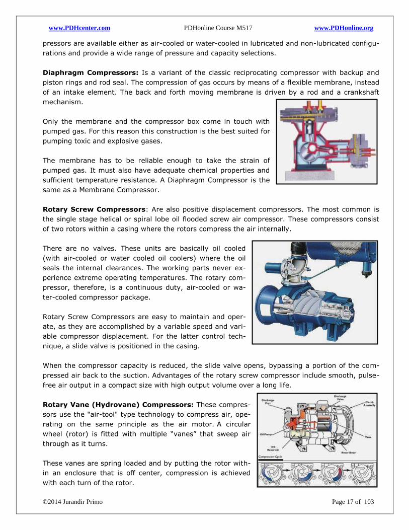
The universal types of compressors are specified by:
The number of compression stages;
Cooling method (air, water, oil);
Drive method (motor, engine, steam, other);
Lubrication (oil free means no lubricating oil contacts the compressed air).
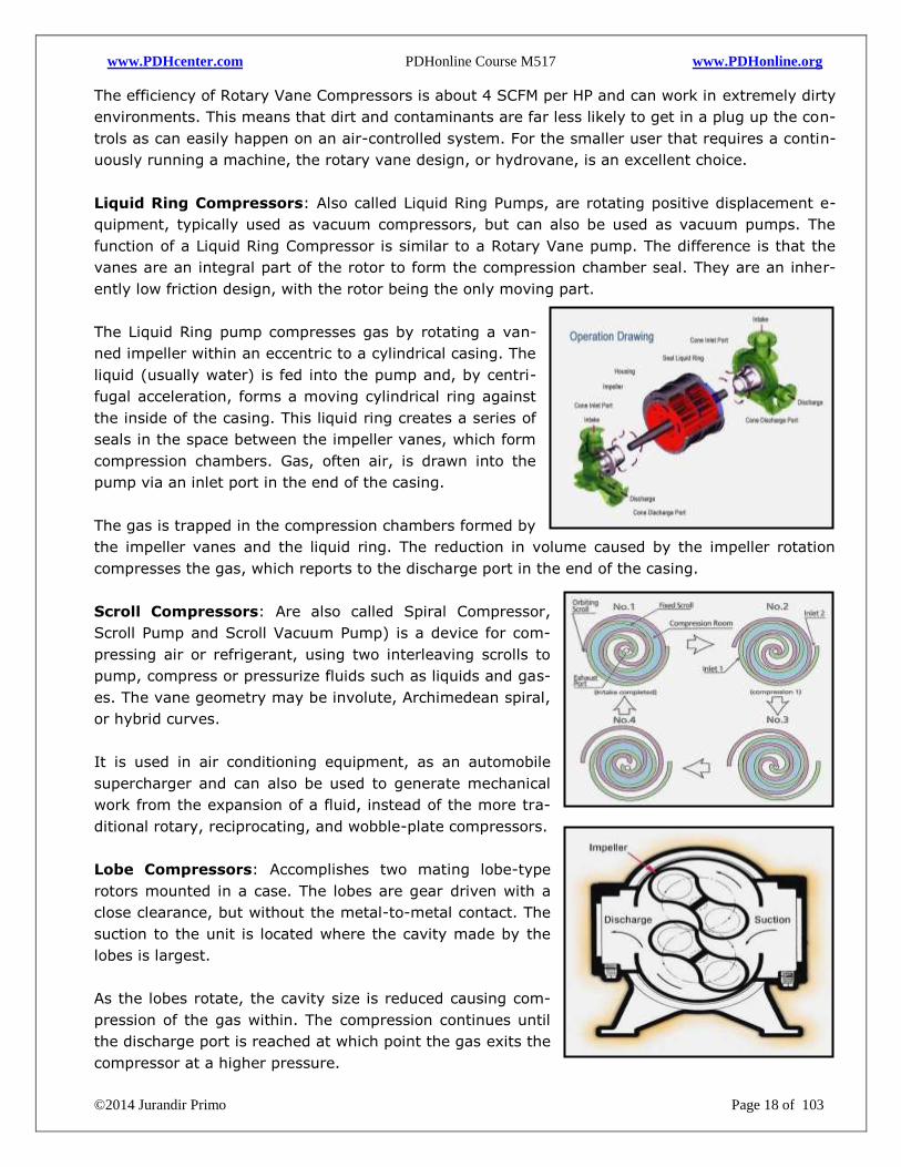
Reciprocating Air Compressors: Reciprocating Air Compressors are positive displacement ma-
chines, meaning that they increase the pressure of the air by reducing its volume. This means they
are taking in successive volumes of air, which is confined within a closed space, and elevating this
air to a higher pressure.
The Reciprocating Air Compressor accomplishes this by a
piston within a cylinder, as the compressing and displa-
cing element is specified as single or double-stage and
single or double acting.
Single-stage: Is when the entire compression is
accomplished with a single cylinder or a group of
cylinders in parallel generally used for pressures in
the range of 70 psig to 100 psig. Single acting -
when the compressing is accomplished using only
one side of the piston.
Double-stage: Is when two or more steps of compression are grouped in series generally
used for pressures in the range of 100 psig to 250 psig. Double acting - are those using
both sides of the piston.
The load reduction is achieved by unloading individual cylinders by throttling the suction pressure
to the cylinder or bypassing air either within or outside the compressor. The capacity control is a-
chieved by varying speed in engine-driven units through fuel flow control. Reciprocating Air Com-
www.PDHcenter.com PDHonline Course M517 www.PDHonline.org
©2014 Jurandir Primo Page 17 of 103
pressors are available either as air-cooled or water-cooled in lubricated and non-lubricated configu-
rations and provide a wide range of pressure and capacity selections.
Diaphragm Compressors: Is a variant of the classic reciprocating compressor with backup and
piston rings and rod seal. The compression of gas occurs by means of a flexible membrane, instead
of an intake element. The back and forth moving membrane is driven by a rod and a crankshaft
mechanism.
Only the membrane and the compressor box come in touch with
pumped gas. For this reason this construction is the best suited for
pumping toxic and explosive gases.
The membrane has to be reliable enough to take the strain of
pumped gas. It must also have adequate chemical properties and
sufficient temperature resistance. A Diaphragm Compressor is the
same as a Membrane Compressor.
Rotary Screw Compressors: Are also positive displacement compressors. The most common is
the single stage helical or spiral lobe oil flooded screw air compressor. These compressors consist
of two rotors within a casing where the rotors compress the air internally.
There are no valves. These units are basically oil cooled
(with air-cooled or water cooled oil coolers) where the oil
seals the internal clearances. The working parts never ex-
perience extreme operating temperatures. The rotary com-
pressor, therefore, is a continuous duty, air-cooled or wa-
ter-cooled compressor package.
Rotary Screw Compressors are easy to maintain and oper-
ate, as they are accomplished by a variable speed and vari-
able compressor displacement. For the latter control tech-
nique, a slide valve is positioned in the casing.
When the compressor capacity is reduced, the slide valve opens, bypassing a portion of the com-
pressed air back to the suction. Advantages of the rotary screw compressor include smooth, pulse-
free air output in a compact size with high output volume over a long life.
Rotary Vane (Hydrovane) Compressors: These compres-
sors use the "air-tool" type technology to compress air, ope-
rating on the same principle as the air motor. A circular
wheel (rotor) is fitted with multiple “vanes” that sweep air
through as it turns.
These vanes are spring loaded and by putting the rotor with-
in an enclosure that is off center, compression is achieved
with each turn of the rotor.
www.PDHcenter.com PDHonline Course M517 www.PDHonline.org
©2014 Jurandir Primo Page 18 of 103
The efficiency of Rotary Vane Compressors is about 4 SCFM per HP and can work in extremely dirty
environments. This means that dirt and contaminants are far less likely to get in a plug up the con-
trols as can easily happen on an air-controlled system. For the smaller user that requires a contin-
uously running a machine, the rotary vane design, or hydrovane, is an excellent choice.
Liquid Ring Compressors: Also called Liquid Ring Pumps, are rotating positive displacement e-
quipment, typically used as vacuum compressors, but can also be used as vacuum pumps. The
function of a Liquid Ring Compressor is similar to a Rotary Vane pump. The difference is that the
vanes are an integral part of the rotor to form the compression chamber seal. They are an inher-
ently low friction design, with the rotor being the only moving part.
The Liquid Ring pump compresses gas by rotating a van-
ned impeller within an eccentric to a cylindrical casing. The
liquid (usually water) is fed into the pump and, by centri-
fugal acceleration, forms a moving cylindrical ring against
the inside of the casing. This liquid ring creates a series of
seals in the space between the impeller vanes, which form
compression chambers. Gas, often air, is drawn into the
pump via an inlet port in the end of the casing.
The gas is trapped in the compression chambers formed by
the impeller vanes and the liquid ring. The reduction in volume caused by the impeller rotation
compresses the gas, which reports to the discharge port in the end of the casing.
Scroll Compressors: Are also called Spiral Compressor,
Scroll Pump and Scroll Vacuum Pump) is a device for com-
pressing air or refrigerant, using two interleaving scrolls to
pump, compress or pressurize fluids such as liquids and gas-
es. The vane geometry may be involute, Archimedean spiral,
or hybrid curves.
It is used in air conditioning equipment, as an automobile
supercharger and can also be used to generate mechanical
work from the expansion of a fluid, instead of the more tra-
ditional rotary, reciprocating, and wobble-plate compressors.
Lobe Compressors: Accomplishes two mating lobe-type
rotors mounted in a case. The lobes are gear driven with a
close clearance, but without the metal-to-metal contact. The
suction to the unit is located where the cavity made by the
lobes is largest.
As the lobes rotate, the cavity size is reduced causing com-
pression of the gas within. The compression continues until
the discharge port is reached at which point the gas exits the
compressor at a higher pressure.
www.PDHcenter.com PDHonline Course M517 www.PDHonline.org
©2014 Jurandir Primo Page 19 of 103
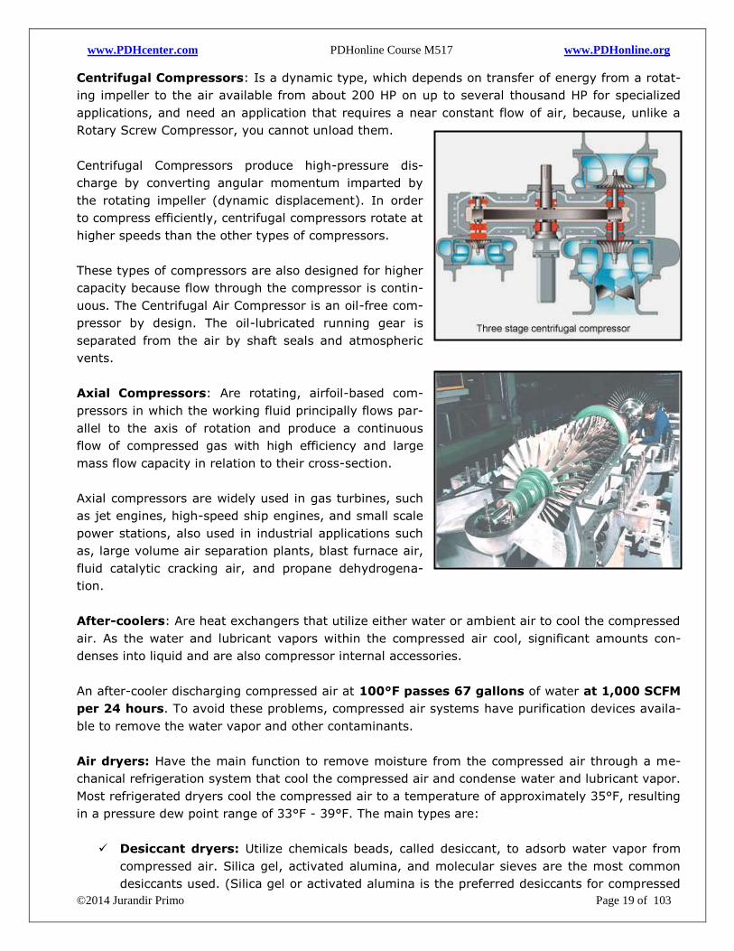
Centrifugal Compressors: Is a dynamic type, which depends on transfer of energy from a rotat-
ing impeller to the air available from about 200 HP on up to several thousand HP for specialized
applications, and need an application that requires a near constant flow of air, because, unlike a
Rotary Screw Compressor, you cannot unload them.
Centrifugal Compressors produce high-pressure dis-
charge by converting angular momentum imparted by
the rotating impeller (dynamic displacement). In order
to compress efficiently, centrifugal compressors rotate at
higher speeds than the other types of compressors.
These types of compressors are also designed for higher
capacity because flow through the compressor is contin-
uous. The Centrifugal Air Compressor is an oil-free com-
pressor by design. The oil-lubricated running gear is
separated from the air by shaft seals and atmospheric
vents.
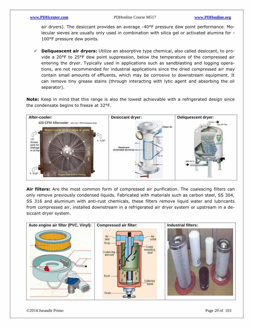
Axial Compressors: Are rotating, airfoil-based com-
pressors in which the working fluid principally flows par-
allel to the axis of rotation and produce a continuous
flow of compressed gas with high efficiency and large
mass flow capacity in relation to their cross-section.
Axial compressors are widely used in gas turbines, such
as jet engines, high-speed ship engines, and small scale
power stations, also used in industrial applications such
as, large volume air separation plants, blast furnace air,
fluid catalytic cracking air, and propane dehydrogena-
tion.
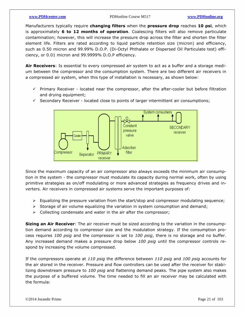
After-coolers: Are heat exchangers that utilize either water or ambient air to cool the compressed
air. As the water and lubricant vapors within the compressed air cool, significant amounts con-
denses into liquid and are also compressor internal accessories.
An after-cooler discharging compressed air at 100°F passes 67 gallons of water at 1,000 SCFM
per 24 hours. To avoid these problems, compressed air systems have purification devices availa-
ble to remove the water vapor and other contaminants.
Air dryers: Have the main function to remove moisture from the compressed air through a me-
chanical refrigeration system that cool the compressed air and condense water and lubricant vapor.
Most refrigerated dryers cool the compressed air to a temperature of approximately 35°F, resulting
in a pressure dew point range of 33°F - 39°F. The main types are:
Desiccant dryers: Utilize chemicals beads, called desiccant, to adsorb water vapor from
compressed air. Silica gel, activated alumina, and molecular sieves are the most common
desiccants used. (Silica gel or activated alumina is the preferred desiccants for compressed
www.PDHcenter.com PDHonline Course M517 www.PDHonline.org
©2014 Jurandir Primo Page 20 of 103
air dryers). The desiccant provides an average -40°F pressure dew point performance. Mo-
lecular sieves are usually only used in combination with silica gel or activated alumina for -
100°F pressure dew points.
Deliquescent air dryers: Utilize an absorptive type chemical, also called desiccant, to pro-
vide a 20°F to 25°F dew point suppression, below the temperature of the compressed air
entering the dryer. Typically used in applications such as sandblasting and logging opera-
tions, are not recommended for industrial applications since the dried compressed air may
contain small amounts of effluents, which may be corrosive to downstream equipment. It
can remove tiny grease stains (through interacting with lytic agent and absorbing the oil
separator).
Note: Keep in mind that this range is also the lowest achievable with a refrigerated design since
the condensate begins to freeze at 32°F.
After-cooler:
Desiccant dryer:
Deliquescent dryer:
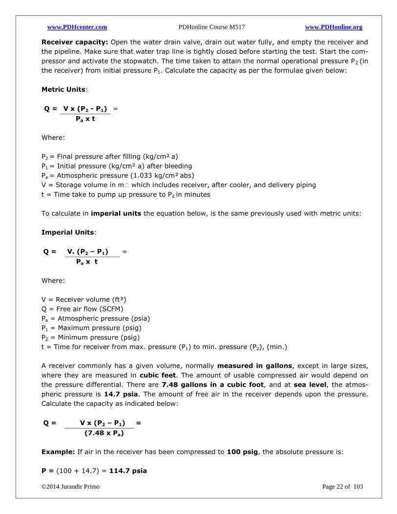
Air filters: Are the most common form of compressed air purification. The coalescing filters can
only remove previously condensed liquids. Fabricated with materials such as carbon steel, SS 304,
SS 316 and aluminum with anti-rust chemicals, these filters remove liquid water and lubricants
from compressed air, installed downstream in a refrigerated air dryer system or upstream in a de-
siccant dryer system.
Auto engine air filter (PVC, Vinyl):
Compressed air filter:
Industrial filters:
www.PDHcenter.com PDHonline Course M517 www.PDHonline.org
©2014 Jurandir Primo Page 21 of 103
Manufacturers typically require changing filters when the pressure drop reaches 10 psi, which
is approximately 6 to 12 months of operation. Coalescing filters will also remove particulate
contamination; however, this will increase the pressure drop across the filter and shorten the filter
element life. Filters are rated according to liquid particle retention size (micron) and efficiency,
such as 0.50 micron and 99.99% D.O.P. (Di-Octyl Phthalate or Dispersed Oil Particulate test) effi-
ciency, or 0.01 micron and 99.9999% D.O.P efficiency.
Air Receivers: Is essential to every compressed air system to act as a buffer and a storage medi-
um between the compressor and the consumption system. There are two different air receivers in
a compressed air system, when this type of installation is necessary, as shown below:
Primary Receiver - located near the compressor, after the after-cooler but before filtration
and drying equipment;
Secondary Receiver - located close to points of larger intermittent air consumptions;
Since the maximum capacity of an air compressor also always exceeds the minimum air consump-
tion in the system - the compressor must modulate its capacity during normal work, often by using
primitive strategies as on/off modulating or more advanced strategies as frequency drives and in-
verters. Air receivers in compressed air systems serve the important purposes of:
Equalizing the pressure variation from the start/stop and compressor modulating sequence;
Storage of air volume equalizing the variation in system consumption and demand;
Collecting condensate and water in the air after the compressor;
Sizing an Air Receiver: The air receiver must be sized according to the variation in the consump-
tion demand according to compressor size and the modulation strategy. If the consumption pro-
cess requires 100 psig and the compressor is set to 100 psig, there is no storage and no buffer.
Any increased demand makes a pressure drop below 100 psig until the compressor controls re-
spond by increasing the volume compressed.
If the compressors operate at 110 psig the difference between 110 psig and 100 psig accounts for
the air stored in the receiver. Pressure and flow controllers can be used after the receiver for stabi-
lizing downstream pressure to 100 psig and flattening demand peaks. The pipe system also makes
the purpose of a buffered volume. The time needed to fill an air receiver may be calculated with
the formula:
www.PDHcenter.com PDHonline Course M517 www.PDHonline.org
©2014 Jurandir Primo Page 22 of 103
Receiver capacity: Open the water drain valve, drain out water fully, and empty the receiver and
the pipeline. Make sure that water trap line is tightly closed before starting the test. Start the com-
pressor and activate the stopwatch. The time taken to attain the normal operational pressure P2 (in
the receiver) from initial pressure P1. Calculate the capacity as per the formulae given below:
Metric Units:
Q = V x (P2 - P1) =
Pa x t
Where:
P2 = Final pressure after filling (kg/cm²
a)
P1 = Initial pressure (kg/cm² a) after bleeding
Pa = Atmospheric pressure (1.033 kg/cm²
abs)
V = Storage volume in mᶟ which includes receiver, after cooler, and delivery piping
t = Time take to pump up pressure to P2 in minutes
To calculate in imperial units the equation below, is the same previously used with metric units:
Imperial Units:
Q = V. (P2 – P1) =
Pa x t
Where:
V = Receiver volume (ft³)
Q = Free air flow (SCFM)
Pa = Atmospheric pressure (psia)
P1 = Maximum pressure (psig)
P2 = Minimum pressure (psig)
t = Time for receiver from max. pressure (P1) to min. pressure (P2), (min.)
A receiver commonly has a given volume, normally measured in gallons, except in large sizes,
where they are measured in cubic feet. The amount of usable compressed air would depend on
the pressure differential. There are 7.48 gallons in a cubic foot, and at sea level, the atmos-
pheric pressure is 14.7 psia. The amount of free air in the receiver depends upon the pressure.
Calculate the capacity as indicated below:
Q = V x (P2 – P1) =
(7.48 x Pa)
Example: If air in the receiver has been compressed to 100 psig, the absolute pressure is:
P = (100 + 14.7) = 114.7 psia
www.PDHcenter.com PDHonline Course M517 www.PDHonline.org
©2014 Jurandir Primo Page 23 of 103
Thus, a receiver with a capacity of 1,000 gallon at 100 psig has the capacity equivalent of:
Q = (1,000 x 114.7) = 1,043 ft³ of free air (FAD)
(7.48 x 14.7)
Example: An industrial plant has an air receiver with 1,000 gallon capacity, and works with com-
pressed air at 100 psig, considering a maximum allowable pressure differential of 10 psi (100 to 90
psig). The available compressed air in storage would be calculated as:
Q = V x (P2 – P1) =
(7.48 x Pa)
Q = 1,000. (100 – 90) = 91 ft³
(7.48 x 14.7)
Example: Using the example above, calculate the time required for a demand rate of 200 CFM
of free air, considering that the pressure to fall from 100 to 90 psig is proportional to the rate of
demand (presuming no supply during the demand event). The time would be:
t = V. (P2 – P1) =
(Q x Pa)
Where:
V = Receiver volume = 1,000 gallons = 134 ft³
P1 = Initial pressure = 100 psig
P2 = Final pressure = 90 psig
Q = CFM of free air = 200 CFM
Pa = Atmospheric pressure = 14.7 psia
t = Time in minutes = (?)
t = 134 x (100 – 90) = 0.456 minutes
(200 x 14.7)
Note: For storage of air in receivers, there must be a pressure differential and an allowable
pressure band. Without an allowable pressure differential, there is no storage. The usable pressure
differential and the air receiver size determine the available storage.
The formula for computing in CFM considering the receiver in gallons (USA) and based on a pump-
up time is as indicated below. As a rule, the pressure would take 1 minute to fall from 100 psig to
78 psig. Be careful not to raise the compressor operating pressure to increase storage.
CFM = Gallons x (P1 – P2)
7.48 x P0 x t
Where:
www.PDHcenter.com PDHonline Course M517 www.PDHonline.org
©2014 Jurandir Primo Page 24 of 103
P1 = Air receiver final pressure, psig
P2 = Air receiver starting pressure, psig
P0 = Atmospheric pressure (14.7 psia)
t = Time to fill the air receiver, min
Gallons = Air receiver capacity, gal
Obs.: The unit of measurement of P2 and P1 is psig or whatever initial pressure you choose to use,
i.e., it can be 100 psig - 50 psig.
Example: Evaluate the previous Reciprocating Compressor capacity with the following data:
V = 2198.4 gallons (8.322 m³)
P1 = 7.26 psig (0.5 kg/cm².a)
P2 = 102 psig (7.03 kg/cm².a)
t = Time taken to fill receiver from P1 to P2 = 4.021 min.
Po = Atmospheric pressure 14.7 psia (1.033 kg/cm².a)
CFM = (102 – 7.26) x 2198.4 = 471 CFM
7.48 x 14.7 x 4.021
Pump-up test: The air compressor that will be tested for capacity is first isolated from the rest of
the system, by operating the isolating non-return valve.
1. The compressor drive motor is shut-off.
2. The receiver connected to this air compressor is emptied.
3. The motor is re-started.
4. The pressure in the receiver begins to raise, for example, 2 kg/cm² (28.44 psi), is noted.
The stopwatch is started at this moment.
5. Stopwatch is stopped when receiver pressure reaches, for example, 8 kg/cm² (113.78 psi).
6. Time elapsed is noted in minutes.
7. Compressor capacity can be evaluated.
Example: A Reciprocating Compressor has the following data, as indicated below. Calculate the
Free Air Delivery (FAD).
Piston displacement = 16.88 m³/min
Theoretical compressor capacity = 14.75 m³/min @ 7 kg/cm²
Receiver Volume = 7.79 m³
Additional volume (piping/water cooler) = 0.4974 m³
Total volume = 8.322 m³
Pump up time = 4.021 min
Initial pressure P1 = 0.5 kg/cm²
Final pressure P2 = 7.03 kg/cm²
Atmospheric pressure P0 = 1.033 kg/cm²,abs
www.PDHcenter.com PDHonline Course M517 www.PDHonline.org
©2014 Jurandir Primo Page 25 of 103
Q = FAD( m³/min) = (P2 - P1) x Total Volume =
Atm. Pressure x Pump up time
Q = FAD(m³/min) = (7.03 - 0.5) x 8.322 = 13.08 m³/min (462 CFM)
(1.033 x 4.021)
The capacity fall rating is 11.32% in relation to initial 14.75 m³/min. This indicates the compressor
performance needs to be investigated further.
Example: Evaluate the previous Reciprocating Compressor capacity with the same previous fol-
lowing data, using imperial units:
V = 294 ft³ (8.322 m³)
P1 = 7.26 psig (0.5 kg/cm².abs)
P2 = 102 psig (7.03 kg/cm².abs)
t = Time taken to fill receiver from P1 to P2 = 4.021 min.
Po = Atmospheric pressure 14.7 psia (1.033 kg/cm².abs)
Q = 294. (102 – 7.26) = 472 CFM
(14.7 x 4.021)
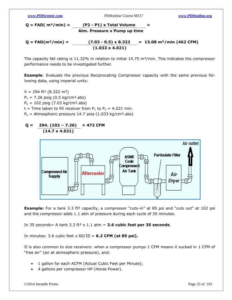
Example: For a tank 3.3 ft³ capacity, a compressor “cuts-in” at 85 psi and “cuts out” at 102 psi
and the compressor adds 1.1 atm of pressure during each cycle of 35 minutes.
In 35 seconds= A tank 3.3 ft³ x 1.1 atm = 3.6 cubic feet per 35 seconds.
In minutes: 3.6 cubic feet x 60/35 = 6.2 CFM (at 85 psi).
It is also common to size receivers: when a compressor pumps 1 CFM means it sucked in 1 CFM of
“free air” (air at atmospheric pressure), and:
1 gallon for each ACFM (Actual Cubic Feet per Minute);
4 gallons per compressor HP (Horse Power).
www.PDHcenter.com PDHonline Course M517 www.PDHonline.org
©2014 Jurandir Primo Page 26 of 103
Important Notes:
As an air receiver should have 1 gallon of capacity for every CFM of compressor output, a
25 HP compressor can theoretically generate about 100 CFM at 90 PSI. Then, the receiv-
er for a 25 HP compressor should have minimum capacity of 100 gallons in size.
Air compressors can generate over 20 gallons of water in an 8-hour operating period. If
not removed, the moisture and contaminants can cause premature failure of the airlines
and pumping equipment.
Intercoolers: are heat exchangers that remove the heat of compression between the
stages of compression, used for overall efficiency of the machine as mechanical energy is
applied to a gas for compression, when the temperature of the gas increases.
After-coolers: are installed after the final stage of compression to reduce the air tempera-
ture. As the air temperature is reduced, water vapor in the air is condensed, separated, col-
lected, and drained from the system. Most of the condensate from a compressor with inter-
cooling is removed in the intercooler(s), and the remainder in the after-cooler.
Approximate discharge temperatures (before after cooling) at 80°F ambient:
Compressor Type 100 psig 160 psig 200 psig
Single-Stage 510 615 -
Two-Stages 325 365 395
Rotary (Oil cooled) 180 - 200 190 - 205 200 - 215
Notes:
1. Compressors from 1 to 50 HP are typically for Reciprocating Compressors.
2. Compressors 100 HP and above are typically Rotary Screw or Centrifugal Compressors.
3. Positive displacement compressors (Reciprocating, Rotary Screw) are isentropic machines.
4. Dynamic compressors (centrifugal or axial compressors) are polytropic machines.
Rules Of Thumb:
1. Air compressors are rated to deliver 4 to 5 CFM per HP at 100 psig discharge pressure.
2. As a basic rule, 1 HP compresses approximately 5 CFM using the pressure at 120 psi.
3. A 50 HP compressor rejects approximately 126,000 BTU per hour for heat recovery.
4. The water vapor content at 100°F of saturated compressed air is about 2 gallons per hour for
each 100 CFM of compressor capacity.
5. Every 20°F temperature drop in saturated compressed air at constant pressure, 50% of the
water vapor condenses to liquid.
6. At 100 psig, every 20°F increase in saturated air the temperature, doubles the amount of
moisture in the air.
7. Most water-cooled after-coolers require about 3 GPM per 100 CFM of to discharge com-
pressed air at an air temperature of 100 psig. Every 2 psig change equals 1% change in HP.
www.PDHcenter.com PDHonline Course M517 www.PDHonline.org
©2014 Jurandir Primo Page 27 of 103
Example: A shop Reciprocating Compressor works with a net displacement of 10 in³, normally at
600 rpm. The approximate cubic feet of compressed air has an overall 10 - 1 compression ratio.
Define the compressor application. Calculate the incoming volumetric air flow. If the compressor
takes in 10 in³ of air for each revolution (remember: 1728 ft³ = 12³ inches), then:
CFM = 600 RPM x 10 in³/1728 in³/ft³ = 3.47 CFM.
Since the compression ratio is 10 -1, the compressed air is:
CFM = 3.47/10 = 0.347 CFM.
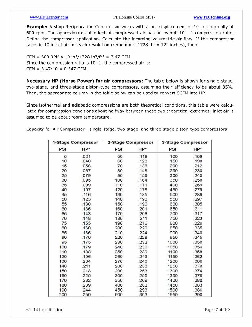
Necessary HP (Horse Power) for air compressors: The table below is shown for single-stage,
two-stage, and three-stage piston-type compressors, assuming their efficiency to be about 85%.
Then, the appropriate column in the table below can be used to convert SCFM into HP.
Since isothermal and adiabatic compressions are both theoretical conditions, this table were calcu-
lated for compression conditions about halfway between these two theoretical extremes. Inlet air is
assumed to be about room temperature.
Capacity for Air Compressor - single-stage, two-stage, and three-stage piston-type compressors:
www.PDHcenter.com PDHonline Course M517 www.PDHonline.org
©2014 Jurandir Primo Page 28 of 103
Example: According to compressed air theory, 1 HP compresses approximately 5 CFM using the
pressure at 120 psi. Check the table for a 1-stage compressor.
The column for 1-stage compressor and 120 psi the table shows = 0.196 HP, then:
N = 5 CFM x 0.196 = 0.98 HP (~ 1 HP)
Example: A shop Reciprocating Compressor works with a net displacement of 10 in³, normally at
600 rpm. The approximate cubic feet of compressed air has an overall 10 - 1 compression ratio.
Define the compressor application. (Remember: 1728 ft³ = 12³ inches).
If the compressor takes in 10 in³ of air for each revolution, then:
CFM = 600 RPM x 10 in³/1728 in³/ft³ = 3.47 CFM.
Since the compression ratio is 10 -1, the compressed air is:
CFM = 3.47/10 = 0.347 CFM.
Conversion units to remember:
1 m³/min = CFM x 35.31
1 m³/h = Nm³/hr x ~1.23
1 SCFM = CFM x ~1.17
High pressure off-line air storage: Some compressed air systems use a very large demand
event that happens infrequently. In others, large air compressors can often take several minutes
before going online. The practical formula is:
Q = CFM x Pa
P
Where:
CFM = Cubic feet per minute;
Pa = Atmospheric pressure = 14.7 psia;
P = Normal pressure, psig.
Example: A plant had three 3,000 CFM centrifugal air compressors. Two supplied the plant; the
third was left on standby. A few times a year, a compressor would shut down unexpectedly. The
operating pressure fell below the required 80 psig, resulting in machine shutdowns. How to give
solution to this problem?
Using above formula, the startup time for a compressor with a 10 psig differential would require:
Q = 3000 CFM x 14.7 psia =
10 psig
Q = 4410 ft³ x 7.48 = 32,987 gallons.
www.PDHcenter.com PDHonline Course M517 www.PDHonline.org
©2014 Jurandir Primo Page 29 of 103
The manufacturer elected to use a high-pressure off-line storage. A small, high-pressure air com-
pressor capable of providing 300 psig was installed, as well as, a 1,500 gallon air receiver and
the required accessories to reduce the pressure to 80 psig, then:
V1 = 1500 gallon = 200.53 ft³
7.48
V2 = 200.53 x (300 psig – 80 psig) = 3001 ft³
14.7 psia
Obs.: The system worked as designed and shutdown problems were eliminated. A complete under-
standing of a compressed air system is essential to implementing storage solutions.
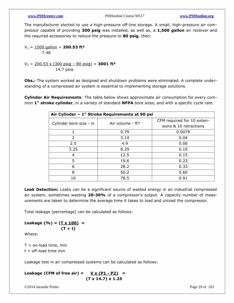
Cylinder Air Requirements: The table below shows approximate air consumption for every com-
mon 1" stroke cylinder, in a variety of standard NFPA bore sizes, and with a specific cycle rate.
Air Cylinder – 1” Stroke Requirements at 90 psi
Cylinder bore size - in Air volume - ft³ CFM required for 10 exten-
sions & 10 retractions
1 0.79 0.0079
2 3.14 0.04
2.5 4.9 0.06
3.25 8.29 0.10
4 12.5 0.15
5 19.6 0.23
6 28.2 0.33
8 50.2 0.60
10 78.5 0.91
Leak Detection: Leaks can be a significant source of wasted energy in an industrial compressed
air system, sometimes wasting 20-30% of a compressor’s output. A capacity number of meas-
urements are taken to determine the average time it takes to load and unload the compressor.
Total leakage (percentage) can be calculated as follows:
Leakage (%) = (T x 100) =
(T + t)
Where:
T = on-load time, min
t = off-load time min
Leakage test in air compressed systems can be calculated as follows:
Leakage (CFM of free air) = V x (P1 - P2) =
(T x 14.7) x 1.25
www.PDHcenter.com PDHonline Course M517 www.PDHonline.org
©2014 Jurandir Primo Page 30 of 103
Where:
V = Total volume, ft³.
P1 = Inlet Pressure, psig
P2 = Exhaust pressure, psig
T = Load time, min
Obs.: The 1.25 multiplier corrects leakage to normal the pressure differential across an orifice.
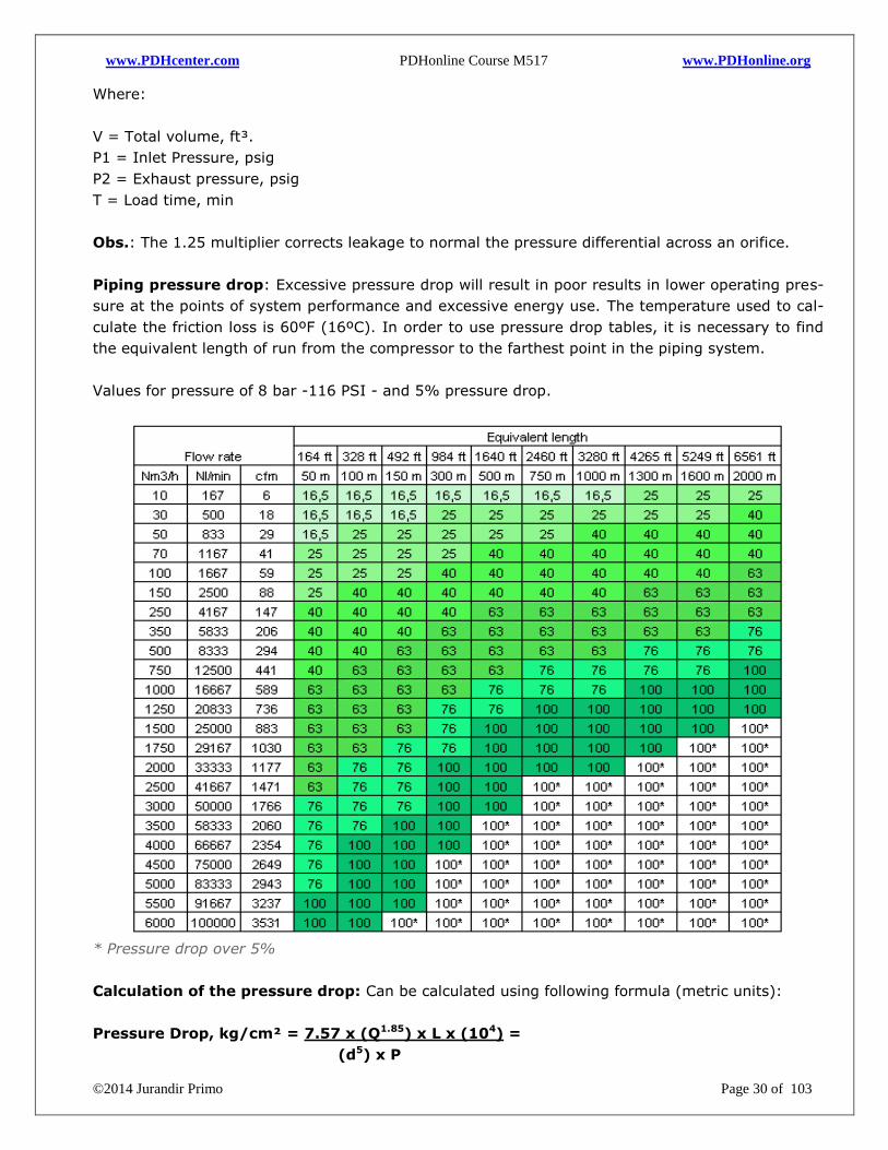
Piping pressure drop: Excessive pressure drop will result in poor results in lower operating pres-
sure at the points of system performance and excessive energy use. The temperature used to cal-
culate the friction loss is 60ºF (16ºC). In order to use pressure drop tables, it is necessary to find
the equivalent length of run from the compressor to the farthest point in the piping system.
Values for pressure of 8 bar -116 PSI - and 5% pressure drop.
* Pressure drop over 5%
Calculation of the pressure drop: Can be calculated using following formula (metric units):
Pressure Drop, kg/cm² = 7.57 x (Q1.85) x L x (104) =
(d5) x P
www.PDHcenter.com PDHonline Course M517 www.PDHonline.org
©2014 Jurandir Primo Page 31 of 103
Where:
Q = Air flow in m³/min (FAD)
L = Length of pipeline (m)
d = inside diameter of pipe (mm)
P = Initial pressure, kg/cm²
Allowable pressure drop in pipelines; According to IS: 6202, for plants, covering large area, the
pressure drop up to 8 psi (~0.5 kg/cm²) may be acceptable. The pressure drop should not ex-
ceed 45 psi (~3 kg/cm²) at the farthest end of the line. Facilities, such as hospitals, may require
instrument air pressure up to 10 bar (150 psi) and tighter specifications for air quality.
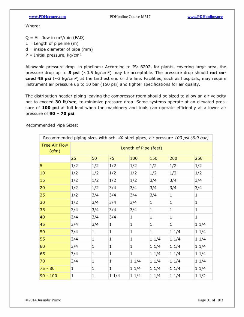
The distribution header piping leaving the compressor room should be sized to allow an air velocity
not to exceed 30 ft/sec, to minimize pressure drop. Some systems operate at an elevated pres-
sure of 100 psi at full load when the machinery and tools can operate efficiently at a lower air
pressure of 90 – 70 psi.
Recommended Pipe Sizes:
Recommended piping sizes with sch. 40 steel pipes, air pressure 100 psi (6.9 bar)
Free Air Flow
(cfm) Length of Pipe (feet)
25 50 75 100 150 200 250
5 1/2 1/2 1/2 1/2 1/2 1/2 1/2
10 1/2 1/2 1/2 1/2 1/2 1/2 1/2
15 1/2 1/2 1/2 1/2 3/4 3/4 3/4
20 1/2 1/2 3/4 3/4 3/4 3/4 3/4
25 1/2 3/4 3/4 3/4 3/4 1 1
30 1/2 3/4 3/4 3/4 1 1 1
35 3/4 3/4 3/4 3/4 1 1 1
40 3/4 3/4 3/4 1 1 1 1
45 3/4 3/4 1 1 1 1 1 1/4
50 3/4 1 1 1 1 1 1/4 1 1/4
55 3/4 1 1 1 1 1/4 1 1/4 1 1/4
60 3/4 1 1 1 1 1/4 1 1/4 1 1/4
65 3/4 1 1 1 1 1/4 1 1/4 1 1/4
70 3/4 1 1 1 1/4 1 1/4 1 1/4 1 1/4
75 - 80 1 1 1 1 1/4 1 1/4 1 1/4 1 1/4
90 - 100 1 1 1 1/4 1 1/4 1 1/4 1 1/4 1 1/2
www.PDHcenter.com PDHonline Course M517 www.PDHonline.org
©2014 Jurandir Primo Page 32 of 103
PNEUMATIC VALVES:
Pneumatic valves are necessary to control the pressure, flow rate and direction of a fluid. At some
point, in an industrial or manufacturing process, compressed air is released, making a valve to
open or close. The pneumatic valve can also be used as an air cylinder enclosed in a main valve. A
pneumatic solenoid valve is also called a compressed air piloted valve. The mixture of a solenoid
and pneumatic valve makes it twofold. The bigger solenoid valve is activated by a smaller pneu-
matic valve.
1. Directional Control Valves:
Directional control valves ensure the flow of air between air ports by opening, closing and switch-
ing their internal connections. Their classification is determined by the number of ports or open-
ings also called ways, the number of switching positions and its method of operation. Common
types of directional control valves include 2/2, 3/2, 5/2, etc. The first number represents the
number of ways (2-way, 3-way, 4-way); the second number represents the number of posi-
tions.
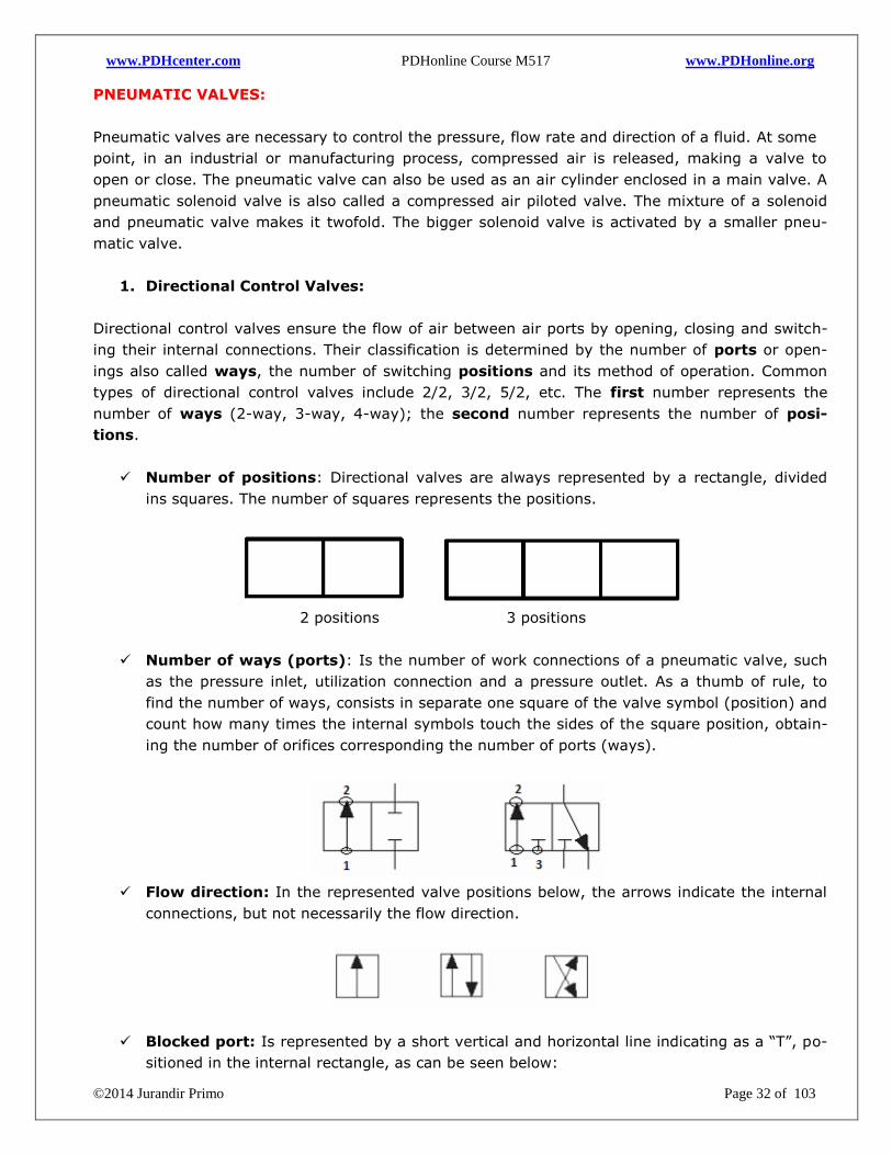
Number of positions: Directional valves are always represented by a rectangle, divided
ins squares. The number of squares represents the positions.
2 positions 3 positions
Number of ways (ports): Is the number of work connections of a pneumatic valve, such
as the pressure inlet, utilization connection and a pressure outlet. As a thumb of rule, to
find the number of ways, consists in separate one square of the valve symbol (position) and
count how many times the internal symbols touch the sides of the square position, obtain-
ing the number of orifices corresponding the number of ports (ways).
Flow direction: In the represented valve positions below, the arrows indicate the internal
connections, but not necessarily the flow direction.
Blocked port: Is represented by a short vertical and horizontal line indicating as a “T”, po-
sitioned in the internal rectangle, as can be seen below:
www.PDHcenter.com PDHonline Course M517 www.PDHonline.org
©2014 Jurandir Primo Page 33 of 103
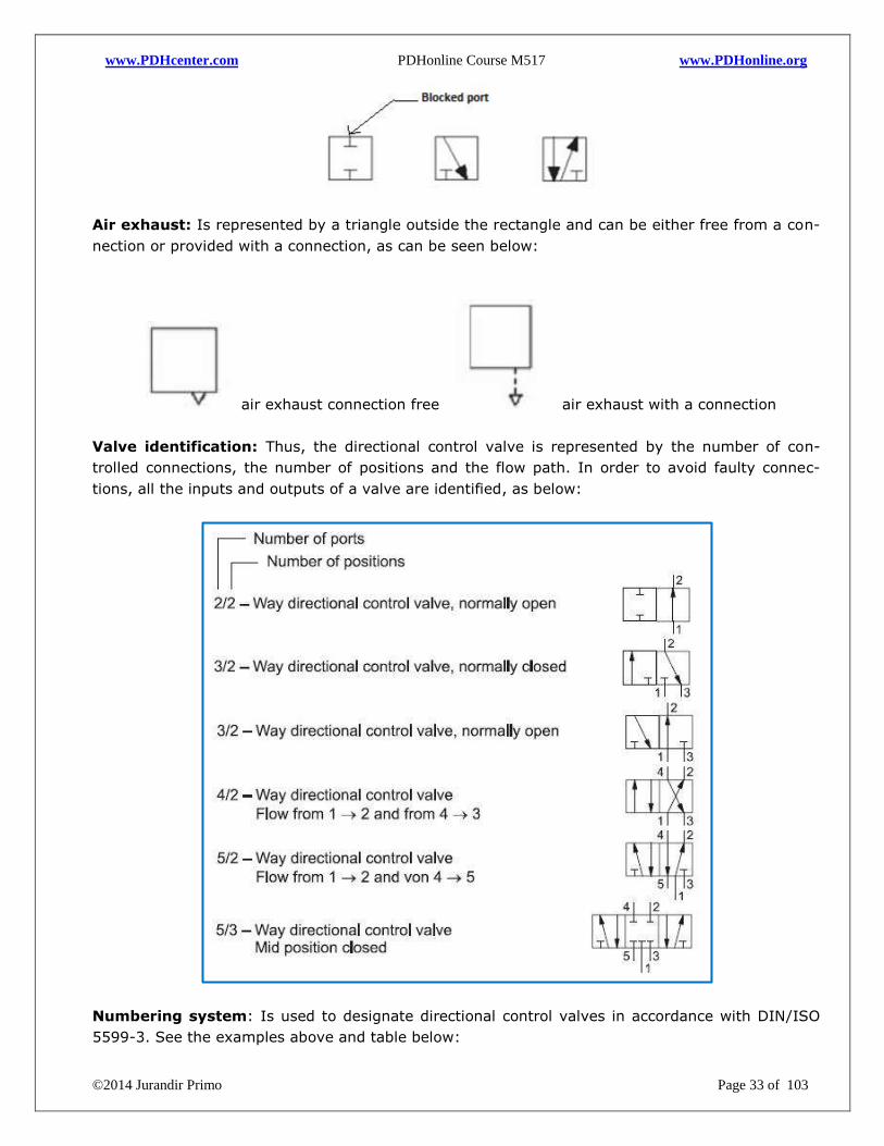
Air exhaust: Is represented by a triangle outside the rectangle and can be either free from a con-
nection or provided with a connection, as can be seen below:
air exhaust connection free air exhaust with a connection
Valve identification: Thus, the directional control valve is represented by the number of con-
trolled connections, the number of positions and the flow path. In order to avoid faulty connec-
tions, all the inputs and outputs of a valve are identified, as below:
Numbering system: Is used to designate directional control valves in accordance with DIN/ISO
5599-3. See the examples above and table below:
www.PDHcenter.com PDHonline Course M517 www.PDHonline.org
©2014 Jurandir Primo Page 34 of 103
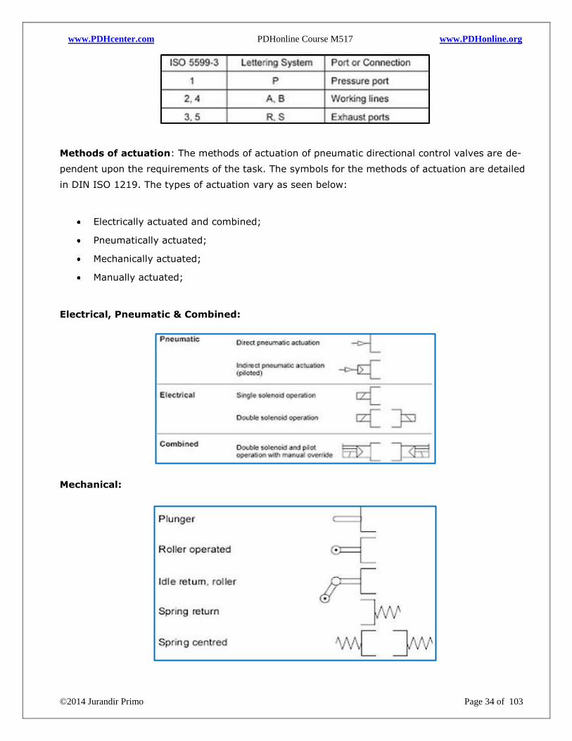
Methods of actuation: The methods of actuation of pneumatic directional control valves are de-
pendent upon the requirements of the task. The symbols for the methods of actuation are detailed
in DIN ISO 1219. The types of actuation vary as seen below:
Electrically actuated and combined;
Pneumatically actuated;
Mechanically actuated;
Manually actuated;
Electrical, Pneumatic & Combined:
Mechanical:
www.PDHcenter.com PDHonline Course M517 www.PDHonline.org
©2014 Jurandir Primo Page 35 of 103
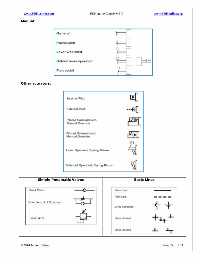
Manual:
Other actuators:
Simple Pneumatic Valves
Basic Lines
www.PDHcenter.com PDHonline Course M517 www.PDHonline.org
©2014 Jurandir Primo Page 36 of 103
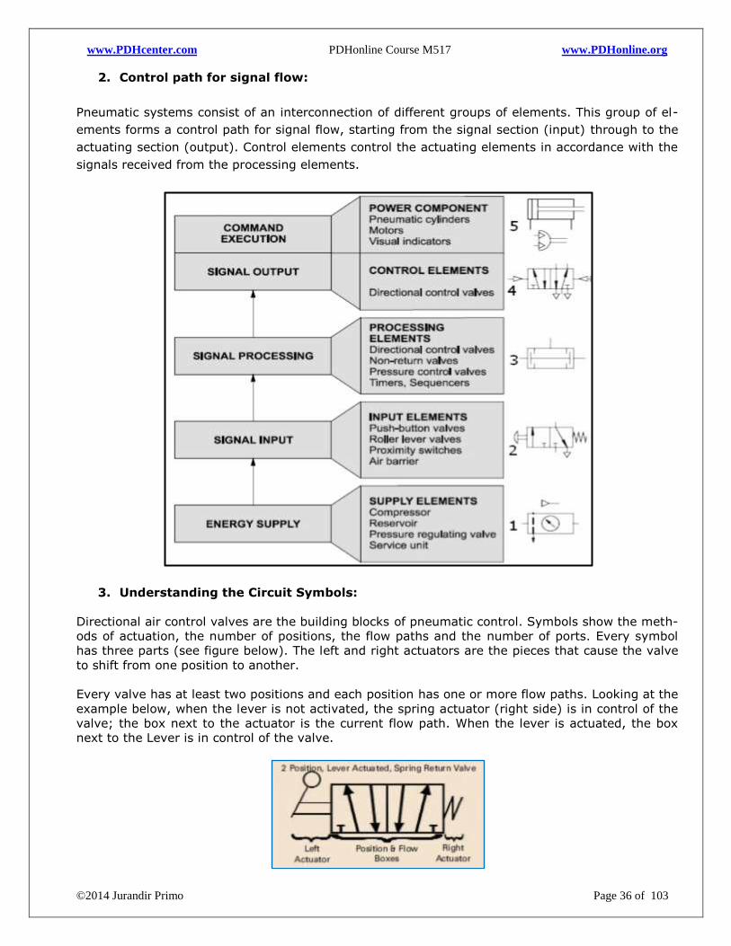
2. Control path for signal flow:
Pneumatic systems consist of an interconnection of different groups of elements. This group of el-
ements forms a control path for signal flow, starting from the signal section (input) through to the
actuating section (output). Control elements control the actuating elements in accordance with the
signals received from the processing elements.
3. Understanding the Circuit Symbols:
Directional air control valves are the building blocks of pneumatic control. Symbols show the meth-
ods of actuation, the number of positions, the flow paths and the number of ports. Every symbol
has three parts (see figure below). The left and right actuators are the pieces that cause the valve
to shift from one position to another.
Every valve has at least two positions and each position has one or more flow paths. Looking at the
example below, when the lever is not activated, the spring actuator (right side) is in control of the
valve; the box next to the actuator is the current flow path. When the lever is actuated, the box
next to the Lever is in control of the valve.
www.PDHcenter.com PDHonline Course M517 www.PDHonline.org
©2014 Jurandir Primo Page 37 of 103
In the example, above, there are a total of 5 ports. A valve can only be in one “position” at a giv-
en time. Flow is indicated by the arrows in each box. These arrows represent the flow paths of the
valve, when it is that position (depending upon which actuator has control over the valve at that
time). Sometimes a port (such as exhaust) goes directly to atmosphere. A port (or orifice) is
blocked with the symbol “T”:
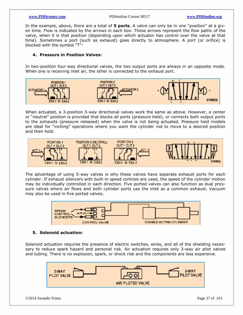
4. Pressure in Position Valves:
In two-position four-way directional valves, the two output ports are always in an opposite mode.
When one is receiving inlet air, the other is connected to the exhaust port.
When actuated, a 3-position 5-way directional valves work the same as above. However, a center
or “neutral” position is provided that blocks all ports (pressure held), or connects both output ports
to the exhausts (pressure released) when the valve is not being actuated. Pressure held models
are ideal for “inching” operations where you want the cylinder rod to move to a desired position
and then hold.
The advantage of using 5-way valves is why these valves have separate exhaust ports for each
cylinder. If exhaust silencers with built-in speed controls are used, the speed of the cylinder motion
may be individually controlled in each direction. Five ported valves can also function as dual pres-
sure valves where air flows and both cylinder ports use the inlet as a common exhaust. Vacuum
may also be used in five ported valves.
5. Solenoid actuation:
Solenoid actuation requires the presence of electric switches, wires, and all of the shielding neces-
sary to reduce spark hazard and personal risk. Air actuation requires only 3-way air pilot valves
and tubing. There is no explosion, spark, or shock risk and the components are less expensive.
www.PDHcenter.com PDHonline Course M517 www.PDHonline.org
©2014 Jurandir Primo Page 38 of 103
6. Detented valve:
A detented valve (means detainer) is one device that holds its position by some mechanical
means such as a spring, ball or cam. In addition, detents are also used to locate the middle posi-
tion in 3- position valves. Most valves hold their position by means of the natural friction of the
rubber seals. Where natural friction is low, such as in packless valves, or where it is not enough for
safety purposes, detented models are recommended.
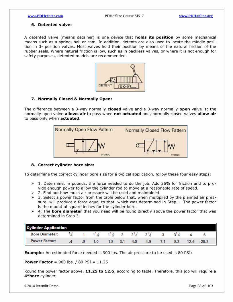
7. Normally Closed & Normally Open:
The difference between a 3-way normally closed valve and a 3-way normally open valve is: the
normally open valve allows air to pass when not actuated and, normally closed valves allow air
to pass only when actuated.
8. Correct cylinder bore size:
To determine the correct cylinder bore size for a typical application, follow these four easy steps:
1. Determine, in pounds, the force needed to do the job. Add 25% for friction and to pro-
vide enough power to allow the cylinder rod to move at a reasonable rate of speed.
2. Find out how much air pressure will be used and maintained.
3. Select a power factor from the table below that, when multiplied by the planned air pres-
sure, will produce a force equal to that, which was determined in Step 1. The power factor
is the mount of square inches for the cylinder bore.
4. The bore diameter that you need will be found directly above the power factor that was
determined in Step 3.
Example: An estimated force needed is 900 lbs. The air pressure to be used is 80 PSI:
Power Factor = 900 lbs. / 80 PSI = 11.25
Round the power factor above, 11.25 to 12.6, according to table. Therefore, this job will require a
4″bore cylinder.
www.PDHcenter.com PDHonline Course M517 www.PDHonline.org
©2014 Jurandir Primo Page 39 of 103
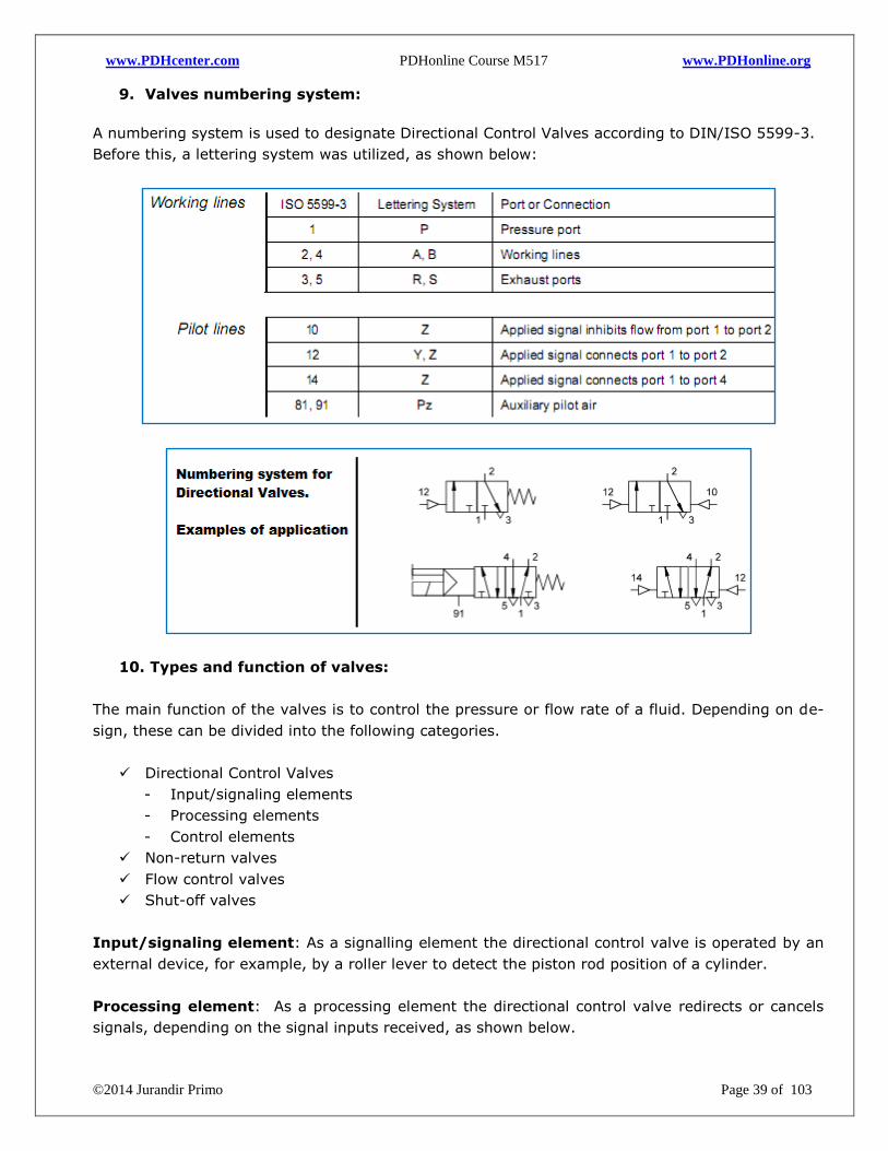
9. Valves numbering system:
A numbering system is used to designate Directional Control Valves according to DIN/ISO 5599-3.
Before this, a lettering system was utilized, as shown below:
10. Types and function of valves:
The main function of the valves is to control the pressure or flow rate of a fluid. Depending on de-
sign, these can be divided into the following categories.
Directional Control Valves
- Input/signaling elements
- Processing elements
- Control elements
Non-return valves
Flow control valves
Shut-off valves
Input/signaling element: As a signalling element the directional control valve is operated by an
external device, for example, by a roller lever to detect the piston rod position of a cylinder.
Processing element: As a processing element the directional control valve redirects or cancels
signals, depending on the signal inputs received, as shown below.
www.PDHcenter.com PDHonline Course M517 www.PDHonline.org
©2014 Jurandir Primo Page 40 of 103
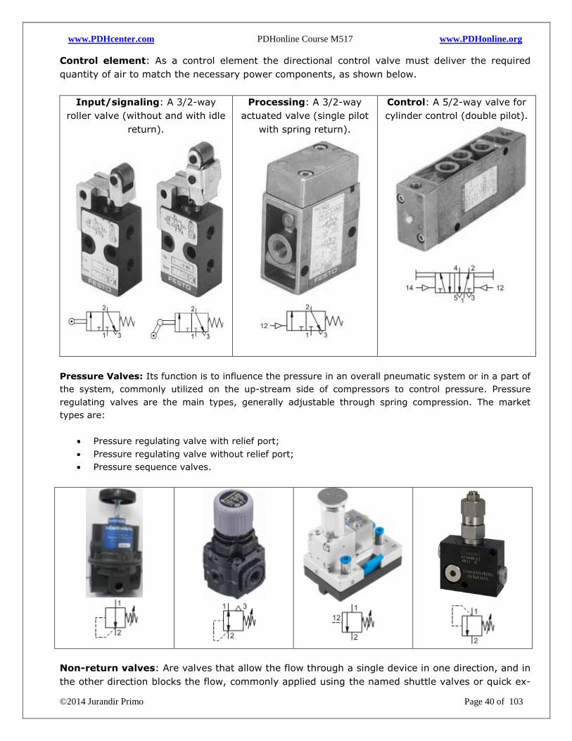
Control element: As a control element the directional control valve must deliver the required
quantity of air to match the necessary power components, as shown below.
Input/signaling: A 3/2-way
roller valve (without and with idle
return).
Processing: A 3/2-way
actuated valve (single pilot
with spring return).
Control: A 5/2-way valve for
cylinder control (double pilot).
Pressure Valves: Its function is to influence the pressure in an overall pneumatic system or in a part of
the system, commonly utilized on the up-stream side of compressors to control pressure. Pressure
regulating valves are the main types, generally adjustable through spring compression. The market
types are:
Pressure regulating valve with relief port;
Pressure regulating valve without relief port;
Pressure sequence valves.
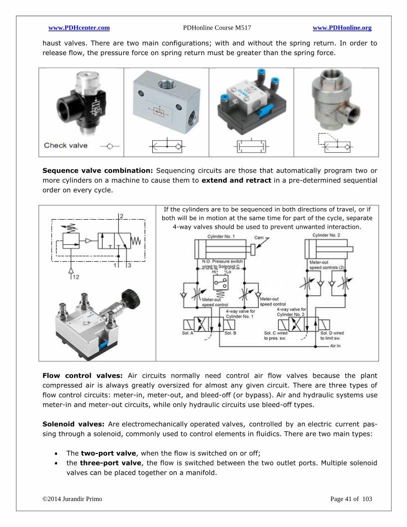
Non-return valves: Are valves that allow the flow through a single device in one direction, and in
the other direction blocks the flow, commonly applied using the named shuttle valves or quick ex-
www.PDHcenter.com PDHonline Course M517 www.PDHonline.org
©2014 Jurandir Primo Page 41 of 103
haust valves. There are two main configurations; with and without the spring return. In order to
release flow, the pressure force on spring return must be greater than the spring force.
Sequence valve combination: Sequencing circuits are those that automatically program two or
more cylinders on a machine to cause them to extend and retract in a pre-determined sequential
order on every cycle.
If the cylinders are to be sequenced in both directions of travel, or if
both will be in motion at the same time for part of the cycle, separate
4-way valves should be used to prevent unwanted interaction.
Flow control valves: Air circuits normally need control air flow valves because the plant
compressed air is always greatly oversized for almost any given circuit. There are three types of
flow control circuits: meter-in, meter-out, and bleed-off (or bypass). Air and hydraulic systems use
meter-in and meter-out circuits, while only hydraulic circuits use bleed-off types.
Solenoid valves: Are electromechanically operated valves, controlled by an electric current pas-
sing through a solenoid, commonly used to control elements in fluidics. There are two main types:
The two-port valve, when the flow is switched on or off;
the three-port valve, the flow is switched between the two outlet ports. Multiple solenoid
valves can be placed together on a manifold.
www.PDHcenter.com PDHonline Course M517 www.PDHonline.org
©2014 Jurandir Primo Page 42 of 103
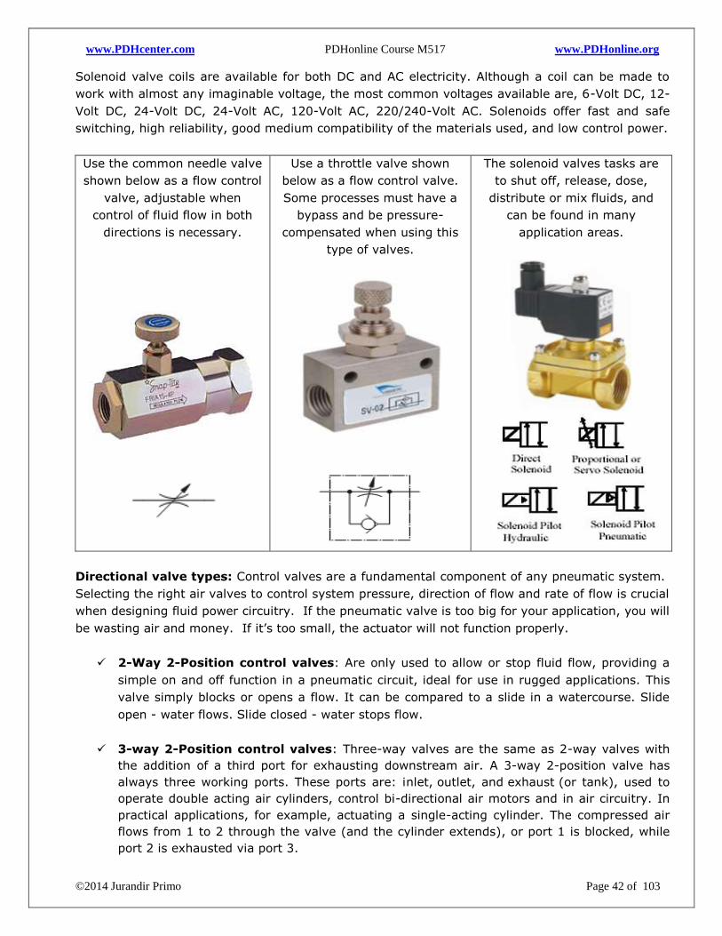
Solenoid valve coils are available for both DC and AC electricity. Although a coil can be made to
work with almost any imaginable voltage, the most common voltages available are, 6-Volt DC, 12-
Volt DC, 24-Volt DC, 24-Volt AC, 120-Volt AC, 220/240-Volt AC. Solenoids offer fast and safe
switching, high reliability, good medium compatibility of the materials used, and low control power.
Use the common needle valve
shown below as a flow control
valve, adjustable when
control of fluid flow in both
directions is necessary.
Use a throttle valve shown
below as a flow control valve.
Some processes must have a
bypass and be pressure-
compensated when using this
type of valves.
The solenoid valves tasks are
to shut off, release, dose,
distribute or mix fluids, and
can be found in many
application areas.
Directional valve types: Control valves are a fundamental component of any pneumatic system.
Selecting the right air valves to control system pressure, direction of flow and rate of flow is crucial
when designing fluid power circuitry. If the pneumatic valve is too big for your application, you will
be wasting air and money. If it’s too small, the actuator will not function properly.
2-Way 2-Position control valves: Are only used to allow or stop fluid flow, providing a
simple on and off function in a pneumatic circuit, ideal for use in rugged applications. This
valve simply blocks or opens a flow. It can be compared to a slide in a watercourse. Slide
open - water flows. Slide closed - water stops flow.
3-way 2-Position control valves: Three-way valves are the same as 2-way valves with
the addition of a third port for exhausting downstream air. A 3-way 2-position valve has
always three working ports. These ports are: inlet, outlet, and exhaust (or tank), used to
operate double acting air cylinders, control bi-directional air motors and in air circuitry. In
practical applications, for example, actuating a single-acting cylinder. The compressed air
flows from 1 to 2 through the valve (and the cylinder extends), or port 1 is blocked, while
port 2 is exhausted via port 3.
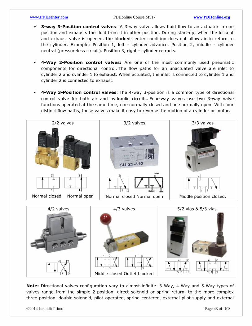
www.PDHcenter.com PDHonline Course M517 www.PDHonline.org
©2014 Jurandir Primo Page 43 of 103
3-way 3-Position control valves: A 3-way valve allows fluid flow to an actuator in one
position and exhausts the fluid from it in other position. During start-up, when the lockout
and exhaust valve is opened, the blocked center condition does not allow air to return to
the cylinder. Example: Position 1, left - cylinder advance. Position 2, middle - cylinder
neutral (pressureless circuit). Position 3, right - cylinder retracts.
4-Way 2-Position control valves: Are one of the most commonly used pneumatic
components for directional control. The flow paths for an unactuated valve are inlet to
cylinder 2 and cylinder 1 to exhaust. When actuated, the inlet is connected to cylinder 1 and
cylinder 2 is connected to exhaust.
4-Way 3-Position control valves: The 4-way 3-position is a common type of directional
control valve for both air and hydraulic circuits. Four-way valves use two 3-way valve
functions operated at the same time, one normally closed and one normally open. With four
distinct flow paths, these valves make it easy to reverse the motion of a cylinder or motor.
2/2 valves
Normal closed Normal open
3/2 valves
Normal closed Normal open
3/3 valves
Middle position closed.
4/2 valves
4/3 valves
Middle closed Outlet blocked
5/2 vias & 5/3 vias
Note: Directional valves configuration vary to almost infinite. 3-Way, 4-Way and 5-Way types of
valves range from the simple 2-position, direct solenoid or spring-return, to the more complex
three-position, double solenoid, pilot-operated, spring-centered, external-pilot supply and external
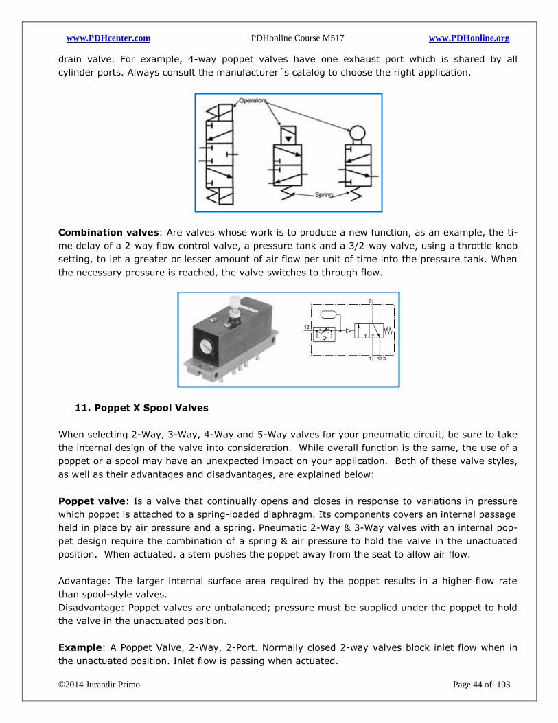
www.PDHcenter.com PDHonline Course M517 www.PDHonline.org
©2014 Jurandir Primo Page 44 of 103
drain valve. For example, 4-way poppet valves have one exhaust port which is shared by all
cylinder ports. Always consult the manufacturer´s catalog to choose the right application.
Combination valves: Are valves whose work is to produce a new function, as an example, the ti-
me delay of a 2-way flow control valve, a pressure tank and a 3/2-way valve, using a throttle knob
setting, to let a greater or lesser amount of air flow per unit of time into the pressure tank. When
the necessary pressure is reached, the valve switches to through flow.
11. Poppet X Spool Valves
When selecting 2-Way, 3-Way, 4-Way and 5-Way valves for your pneumatic circuit, be sure to take
the internal design of the valve into consideration. While overall function is the same, the use of a
poppet or a spool may have an unexpected impact on your application. Both of these valve styles,
as well as their advantages and disadvantages, are explained below:
Poppet valve: Is a valve that continually opens and closes in response to variations in pressure
which poppet is attached to a spring-loaded diaphragm. Its components covers an internal passage
held in place by air pressure and a spring. Pneumatic 2-Way & 3-Way valves with an internal pop-
pet design require the combination of a spring & air pressure to hold the valve in the unactuated
position. When actuated, a stem pushes the poppet away from the seat to allow air flow.
Advantage: The larger internal surface area required by the poppet results in a higher flow rate
than spool-style valves.
Disadvantage: Poppet valves are unbalanced; pressure must be supplied under the poppet to hold
the valve in the unactuated position.
Example: A Poppet Valve, 2-Way, 2-Port. Normally closed 2-way valves block inlet flow when in
the unactuated position. Inlet flow is passing when actuated.
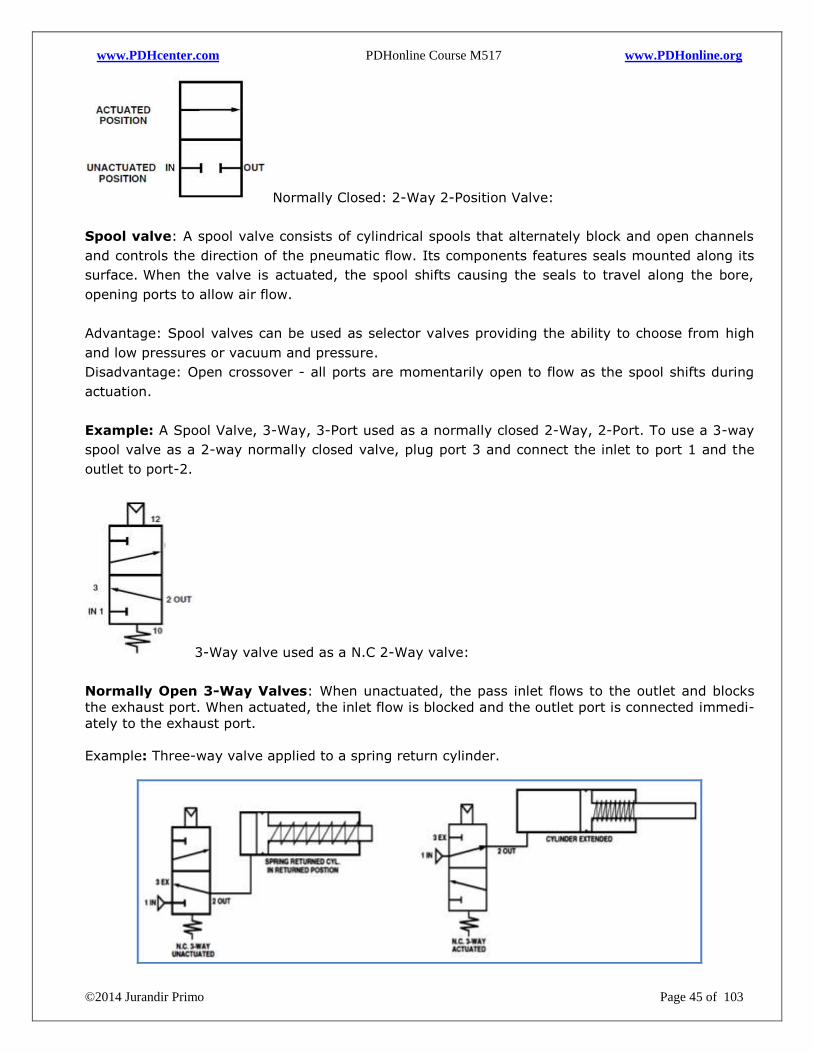
www.PDHcenter.com PDHonline Course M517 www.PDHonline.org
©2014 Jurandir Primo Page 45 of 103
Normally Closed: 2-Way 2-Position Valve:
Spool valve: A spool valve consists of cylindrical spools that alternately block and open channels
and controls the direction of the pneumatic flow. Its components features seals mounted along its
surface. When the valve is actuated, the spool shifts causing the seals to travel along the bore,
opening ports to allow air flow.
Advantage: Spool valves can be used as selector valves providing the ability to choose from high
and low pressures or vacuum and pressure.
Disadvantage: Open crossover - all ports are momentarily open to flow as the spool shifts during
actuation.
Example: A Spool Valve, 3-Way, 3-Port used as a normally closed 2-Way, 2-Port. To use a 3-way
spool valve as a 2-way normally closed valve, plug port 3 and connect the inlet to port 1 and the
outlet to port-2.
3-Way valve used as a N.C 2-Way valve:
Normally Open 3-Way Valves: When unactuated, the pass inlet flows to the outlet and blocks
the exhaust port. When actuated, the inlet flow is blocked and the outlet port is connected immedi-
ately to the exhaust port.
Example: Three-way valve applied to a spring return cylinder.
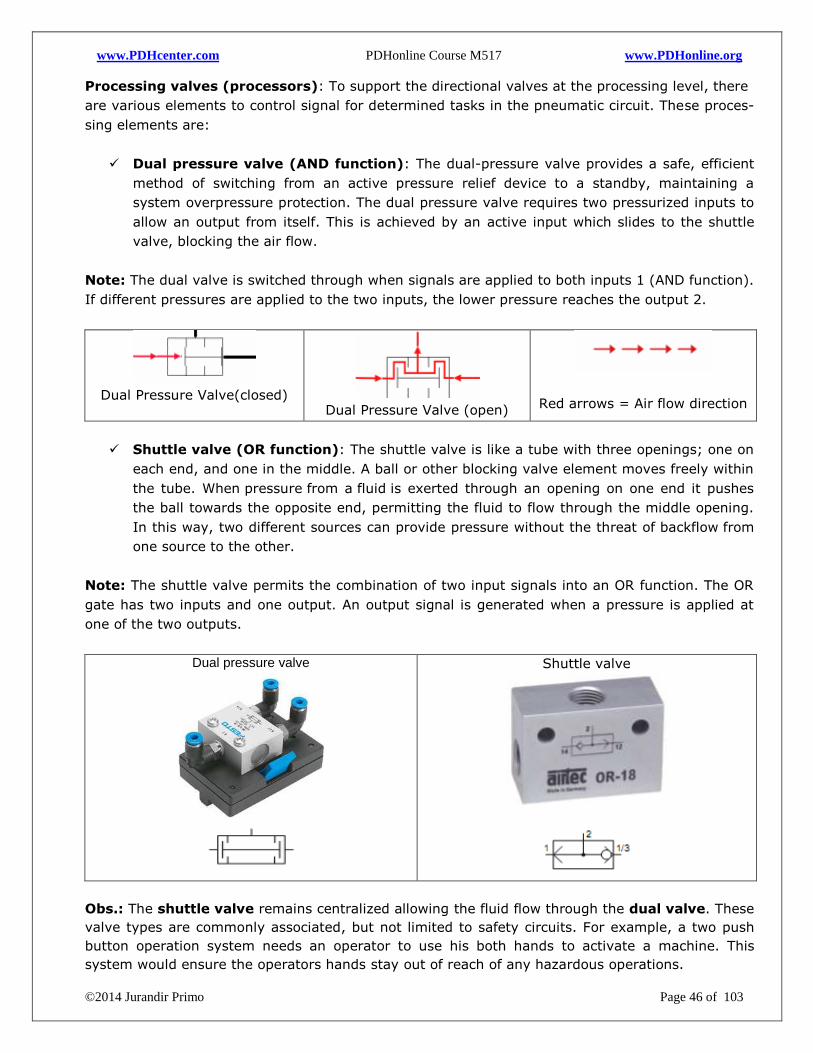
www.PDHcenter.com PDHonline Course M517 www.PDHonline.org
©2014 Jurandir Primo Page 46 of 103
Processing valves (processors): To support the directional valves at the processing level, there
are various elements to control signal for determined tasks in the pneumatic circuit. These proces-
sing elements are:
Dual pressure valve (AND function): The dual-pressure valve provides a safe, efficient
method of switching from an active pressure relief device to a standby, maintaining a
system overpressure protection. The dual pressure valve requires two pressurized inputs to
allow an output from itself. This is achieved by an active input which slides to the shuttle
valve, blocking the air flow.
Note: The dual valve is switched through when signals are applied to both inputs 1 (AND function).
If different pressures are applied to the two inputs, the lower pressure reaches the output 2.
Dual Pressure Valve(closed)
Dual Pressure Valve (open)
Red arrows = Air flow direction
Shuttle valve (OR function): The shuttle valve is like a tube with three openings; one on
each end, and one in the middle. A ball or other blocking valve element moves freely within
the tube. When pressure from a fluid is exerted through an opening on one end it pushes
the ball towards the opposite end, permitting the fluid to flow through the middle opening.
In this way, two different sources can provide pressure without the threat of backflow from
one source to the other.
Note: The shuttle valve permits the combination of two input signals into an OR function. The OR
gate has two inputs and one output. An output signal is generated when a pressure is applied at
one of the two outputs.
Dual pressure valve
Shuttle valve
Obs.: The shuttle valve remains centralized allowing the fluid flow through the dual valve. These
valve types are commonly associated, but not limited to safety circuits. For example, a two push
button operation system needs an operator to use his both hands to activate a machine. This
system would ensure the operators hands stay out of reach of any hazardous operations.
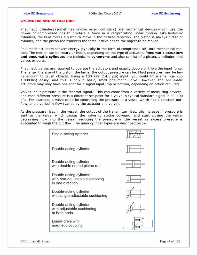
www.PDHcenter.com PDHonline Course M517 www.PDHonline.org
©2014 Jurandir Primo Page 47 of 103
CYLINDERS AND ACTUATORS:
Pneumatic cylinders (sometimes known as air cylinders) are mechanical devices which use the
power of compressed gas to produce a force in a reciprocating linear motion. Like hydraulic
cylinders, the fluid forces a piston to move in the desired direction. The piston is always a disc or
cylinder, and the piston rod transfers the force it develops to the object to be moved.
Pneumatic actuators convert energy (typically in the form of compressed air) into mechanical mo-
tion. The motion can be rotary or linear, depending on the type of actuator. Pneumatic actuators
and pneumatic cylinders are technically synonyms and also consist of a piston, a cylinder, and
valves or ports.
Pneumatic valves are required to operate the actuators and usually double or triple the input force.
The larger the size of the piston, the larger the output pressure can be. Fluid pressures may be lar-
ge enough to crush objects. Using a 100 kPa (14.5 psi) input, you could lift a small car (up
1,000 lbs) easily, and this is only a basic, small pneumatic valve. However, the pneumatic
actuators may only have one spot for a signal input, top or bottom, depending on action required.
Valves input pressure is the "control signal." This can come from a variety of measuring devices,
and each different pressure is a different set point for a valve. A typical standard signal is 20–100
kPa. For example, a valve could be controlling the pressure in a vessel which has a constant out-
flow, and a varied in-flow (varied by the actuator and valve).
As the pressure rises in the vessel, the output of the transmitter rises, this increase in pressure is
sent to the valve, which causes the valve to stroke downard, and start closing the valve,
decreasing flow into the vessel, reducing the pressure in the vessel as excess pressure is
evacuated through the out flow. The main cylinder types are described below:
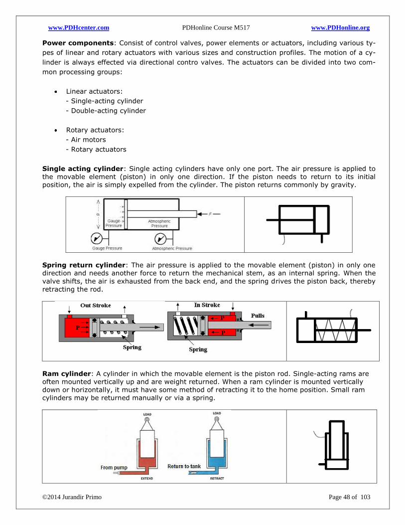
www.PDHcenter.com PDHonline Course M517 www.PDHonline.org
©2014 Jurandir Primo Page 48 of 103
Power components: Consist of control valves, power elements or actuators, including various ty-
pes of linear and rotary actuators with various sizes and construction profiles. The motion of a cy-
linder is always effected via directional contro valves. The actuators can be divided into two com-
mon processing groups:
Linear actuators:
- Single-acting cylinder
- Double-acting cylinder
Rotary actuators:
- Air motors
- Rotary actuators
Single acting cylinder: Single acting cylinders have only one port. The air pressure is applied to
the movable element (piston) in only one direction. If the piston needs to return to its initial
position, the air is simply expelled from the cylinder. The piston returns commonly by gravity.
Spring return cylinder: The air pressure is applied to the movable element (piston) in only one
direction and needs another force to return the mechanical stem, as an internal spring. When the
valve shifts, the air is exhausted from the back end, and the spring drives the piston back, thereby
retracting the rod.
Ram cylinder: A cylinder in which the movable element is the piston rod. Single-acting rams are
often mounted vertically up and are weight returned. When a ram cylinder is mounted vertically
down or horizontally, it must have some method of retracting it to the home position. Small ram
cylinders may be returned manually or via a spring.
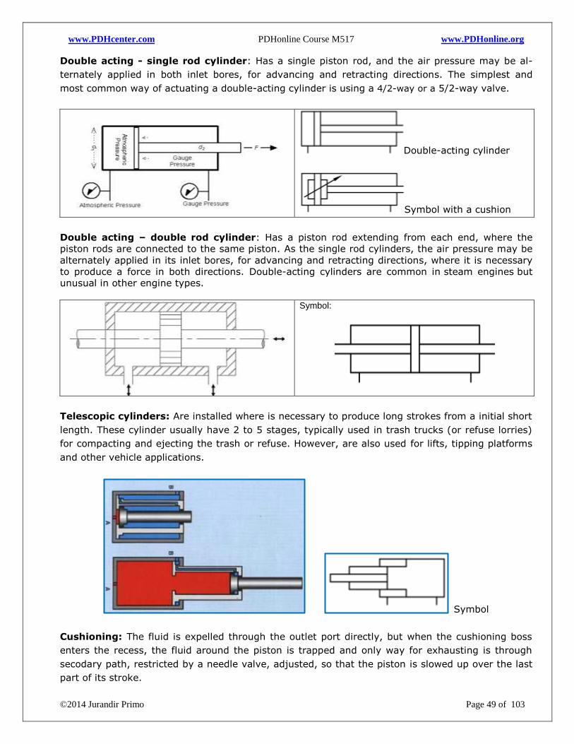
www.PDHcenter.com PDHonline Course M517 www.PDHonline.org
©2014 Jurandir Primo Page 49 of 103
Double acting - single rod cylinder: Has a single piston rod, and the air pressure may be al-
ternately applied in both inlet bores, for advancing and retracting directions. The simplest and
most common way of actuating a double-acting cylinder is using a 4/2-way or a 5/2-way valve.
Double-acting cylinder
Symbol with a cushion
Double acting – double rod cylinder: Has a piston rod extending from each end, where the
piston rods are connected to the same piston. As the single rod cylinders, the air pressure may be
alternately applied in its inlet bores, for advancing and retracting directions, where it is necessary
to produce a force in both directions. Double-acting cylinders are common in steam engines but
unusual in other engine types.
Symbol:
Telescopic cylinders: Are installed where is necessary to produce long strokes from a initial short
length. These cylinder usually have 2 to 5 stages, typically used in trash trucks (or refuse lorries)
for compacting and ejecting the trash or refuse. However, are also used for lifts, tipping platforms
and other vehicle applications.
Symbol
Cushioning: The fluid is expelled through the outlet port directly, but when the cushioning boss
enters the recess, the fluid around the piston is trapped and only way for exhausting is through
secodary path, restricted by a needle valve, adjusted, so that the piston is slowed up over the last
part of its stroke.
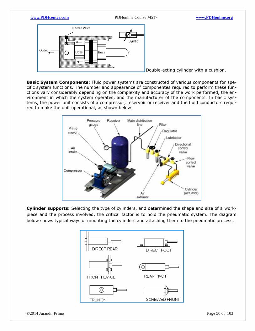
www.PDHcenter.com PDHonline Course M517 www.PDHonline.org
©2014 Jurandir Primo Page 50 of 103
Double-acting cylinder with a cushion.
Basic System Components: Fluid power systems are constructed of various components for spe-
cific system functions. The number and appearance of componentes required to perform these fun-
ctions vary considerably depending on the complexity and accuracy of the work performed, the en-
vironment in which the system operates, and the manufacturer of the components. In basic sys-
tems, the power unit consists of a compressor, reservoir or receiver and the fluid conductors requi-
red to make the unit operational, as shown below:
Cylinder supports: Selecting the type of cylinders, and determined the shape and size of a work-
piece and the process involved, the critical factor is to hold the pneumatic system. The diagram
below shows typical ways of mounting the cylinders and attaching them to the pneumatic process.
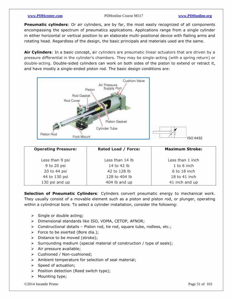
www.PDHcenter.com PDHonline Course M517 www.PDHonline.org
©2014 Jurandir Primo Page 51 of 103
Pneumatic cylinders: Or air cylinders, are by far, the most easily recognized of all components
encompassing the spectrum of pneumatics applications. Applications range from a single cylinder
in either horizontal or vertical position to an elaborate multi-positional device with flailing arms and
rotating head. Regardless of the design, the basic principals and materials used are the same.
Air Cylinders: In a basic concept, air cylinders are pneumatic linear actuators that are driven by a
pressure differential in the cylinder's chambers. They may be single-acting (with a spring return) or
double-acting. Double-sided cylinders can work on both sides of the piston to extend or retract it,
and have mostly a single-ended piston rod. The basic design conditions are:
ISO 6432
Operating Pressure:
Less than 9 psi
9 to 20 psi
20 to 44 psi
44 to 130 psi
130 psi and up
Rated Load / Force:
Less than 14 lb
14 to 42 lb
42 to 128 lb
128 to 404 lb
404 lb and up
Maximum Stroke:
Less than 1 inch
1 to 6 inch
6 to 18 inch
18 to 41 inch
41 inch and up
Selection of Pneumatic Cylinders: Cylinders convert pneumatic energy to mechanical work.
They usually consist of a movable element such as a piston and piston rod, or plunger, operating
within a cylindrical bore. To select a cylinder installation, consider the following:
Single or double acting;
Dimensional standards like ISO, VDMA, CETOP, AFNOR;
Constructional details – Piston rod, tie rod, square tube, rodless, etc.;
Force to be exerted (Bore dia.);
Distance to be moved (stroke);
Surrounding medium (special material of construction / type of seals);
Air pressure available;
Cushioned / Non-cushioned;
Ambient temperature for selection of seal material;
Speed of actuation;
Position detection (Reed switch type);
Mounting type;
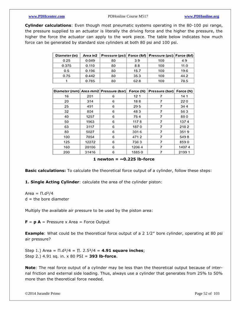
www.PDHcenter.com PDHonline Course M517 www.PDHonline.org
©2014 Jurandir Primo Page 52 of 103
Cylinder calculations: Even though most pneumatic systems operating in the 80-100 psi range,
the pressure supplied to an actuator is literally the driving force and the higher the pressure, the
higher the force the actuator can apply to the work piece. The table below indicates how much
force can be generated by standard size cylinders at both 80 psi and 100 psi.
1 newton = ~0.225 lb-force
Basic calculations: To calculate the theoretical force output of a cylinder, follow these steps:
1. Single Acting Cylinder: calculate the area of the cylinder piston:
Area = Π.d²/4
d = the bore diameter
Multiply the available air pressure to be used by the piston area:
F = p A = Pressure x Area = Force Output
Example: What could be the theoretical force output of a 2 1⁄2″ bore cylinder, operating at 80 psi
air pressure?
Step 1.) Area = Π.d²/4 = ∏. 2.5²/4 = 4.91 square inches;
Step 2.) 4.91 sq. in. x 80 PSI = 393 lb-force.
Note: The real force output of a cylinder may be less than the theoretical output because of inter-
nal friction and external side loading. Thus, always use a cylinder that generates from 25% to 50%
more than the theoretical force needed.
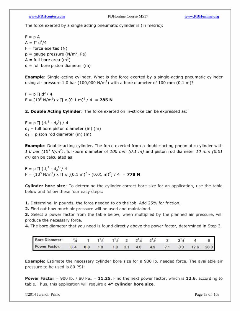
www.PDHcenter.com PDHonline Course M517 www.PDHonline.org
©2014 Jurandir Primo Page 53 of 103
The force exerted by a single acting pneumatic cylinder is (in metric):
F = p A
A = ∏ d2/4
F = force exerted (N)
p = gauge pressure (N/m2, Pa)
A = full bore area (m2)
d = full bore piston diameter (m)
Example: Single-acting cylinder. What is the force exerted by a single-acting pneumatic cylinder
using air pressure 1.0 bar (100,000 N/m2) with a bore diameter of 100 mm (0.1 m)?
F = p ∏ d2 / 4
F = (105 N/m2) x ∏ x (0.1 m)2 / 4 = 785 N
2. Double Acting Cylinder: The force exerted on in-stroke can be expressed as:
F = p ∏ (d12 - d2
2) / 4
d1 = full bore piston diameter (in) (m)
d2 = piston rod diameter (in) (m)
Example: Double-acting cylinder. The force exerted from a double-acting pneumatic cylinder with
1.0 bar (105 N/m2), full-bore diameter of 100 mm (0.1 m) and piston rod diameter 10 mm (0.01
m) can be calculated as:
F = p ∏ (d12 - d2
2) / 4
F = (105 N/m2) x ∏ x [(0.1 m)2 - (0.01 m)2] / 4 = 778 N
Cylinder bore size: To determine the cylinder correct bore size for an application, use the table
below and follow these four easy steps:
1. Determine, in pounds, the force needed to do the job. Add 25% for friction.
2. Find out how much air pressure will be used and maintained.
3. Select a power factor from the table below, when multiplied by the planned air pressure, will
produce the necessary force.
4. The bore diameter that you need is found directly above the power factor, determined in Step 3.
Example: Estimate the necessary cylinder bore size for a 900 lb. needed force. The available air
pressure to be used is 80 PSI:
Power Factor = 900 lb. / 80 PSI = 11.25. Find the next power factor, which is 12.6, according to
table. Thus, this application will require a 4″ cylinder bore size.
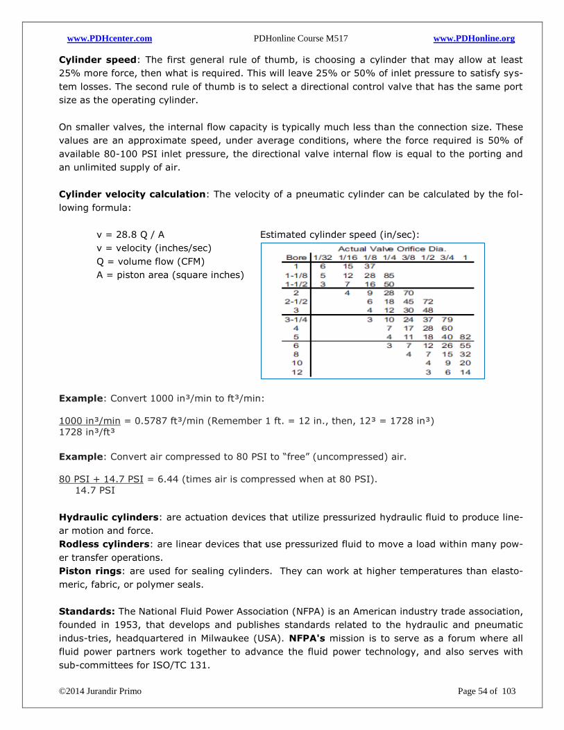
www.PDHcenter.com PDHonline Course M517 www.PDHonline.org
©2014 Jurandir Primo Page 54 of 103
Cylinder speed: The first general rule of thumb, is choosing a cylinder that may allow at least
25% more force, then what is required. This will leave 25% or 50% of inlet pressure to satisfy sys-
tem losses. The second rule of thumb is to select a directional control valve that has the same port
size as the operating cylinder.
On smaller valves, the internal flow capacity is typically much less than the connection size. These
values are an approximate speed, under average conditions, where the force required is 50% of
available 80-100 PSI inlet pressure, the directional valve internal flow is equal to the porting and
an unlimited supply of air.
Cylinder velocity calculation: The velocity of a pneumatic cylinder can be calculated by the fol-
lowing formula:
v = 28.8 Q / A
v = velocity (inches/sec)
Q = volume flow (CFM)
A = piston area (square inches)
Estimated cylinder speed (in/sec):
Example: Convert 1000 in³/min to ft³/min:
1000 in³/min = 0.5787 ft³/min (Remember 1 ft. = 12 in., then, 12³ = 1728 in³)
1728 in³/ft³
Example: Convert air compressed to 80 PSI to “free” (uncompressed) air.
80 PSI + 14.7 PSI = 6.44 (times air is compressed when at 80 PSI).
14.7 PSI
Hydraulic cylinders: are actuation devices that utilize pressurized hydraulic fluid to produce line-
ar motion and force.
Rodless cylinders: are linear devices that use pressurized fluid to move a load within many pow-
er transfer operations.
Piston rings: are used for sealing cylinders. They can work at higher temperatures than elasto-
meric, fabric, or polymer seals.
Standards: The National Fluid Power Association (NFPA) is an American industry trade association,
founded in 1953, that develops and publishes standards related to the hydraulic and pneumatic
indus-tries, headquartered in Milwaukee (USA). NFPA's mission is to serve as a forum where all
fluid power partners work together to advance the fluid power technology, and also serves with
sub-committees for ISO/TC 131.
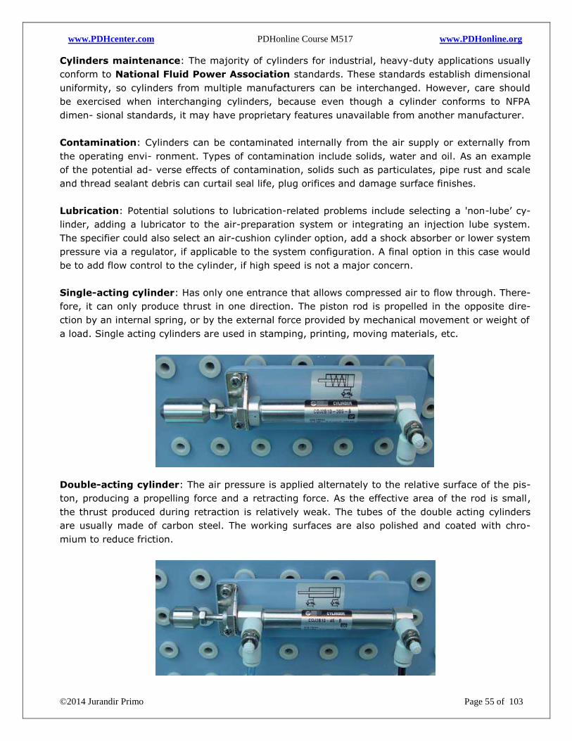
www.PDHcenter.com PDHonline Course M517 www.PDHonline.org
©2014 Jurandir Primo Page 55 of 103
Cylinders maintenance: The majority of cylinders for industrial, heavy-duty applications usually
conform to National Fluid Power Association standards. These standards establish dimensional
uniformity, so cylinders from multiple manufacturers can be interchanged. However, care should
be exercised when interchanging cylinders, because even though a cylinder conforms to NFPA
dimen- sional standards, it may have proprietary features unavailable from another manufacturer.
Contamination: Cylinders can be contaminated internally from the air supply or externally from
the operating envi- ronment. Types of contamination include solids, water and oil. As an example
of the potential ad- verse effects of contamination, solids such as particulates, pipe rust and scale
and thread sealant debris can curtail seal life, plug orifices and damage surface finishes.
Lubrication: Potential solutions to lubrication-related problems include selecting a 'non-lube’ cy-
linder, adding a lubricator to the air-preparation system or integrating an injection lube system.
The specifier could also select an air-cushion cylinder option, add a shock absorber or lower system
pressure via a regulator, if applicable to the system configuration. A final option in this case would
be to add flow control to the cylinder, if high speed is not a major concern.
Single-acting cylinder: Has only one entrance that allows compressed air to flow through. There-
fore, it can only produce thrust in one direction. The piston rod is propelled in the opposite dire-
ction by an internal spring, or by the external force provided by mechanical movement or weight of
a load. Single acting cylinders are used in stamping, printing, moving materials, etc.
Double-acting cylinder: The air pressure is applied alternately to the relative surface of the pis-
ton, producing a propelling force and a retracting force. As the effective area of the rod is small,
the thrust produced during retraction is relatively weak. The tubes of the double acting cylinders
are usually made of carbon steel. The working surfaces are also polished and coated with chro-
mium to reduce friction.
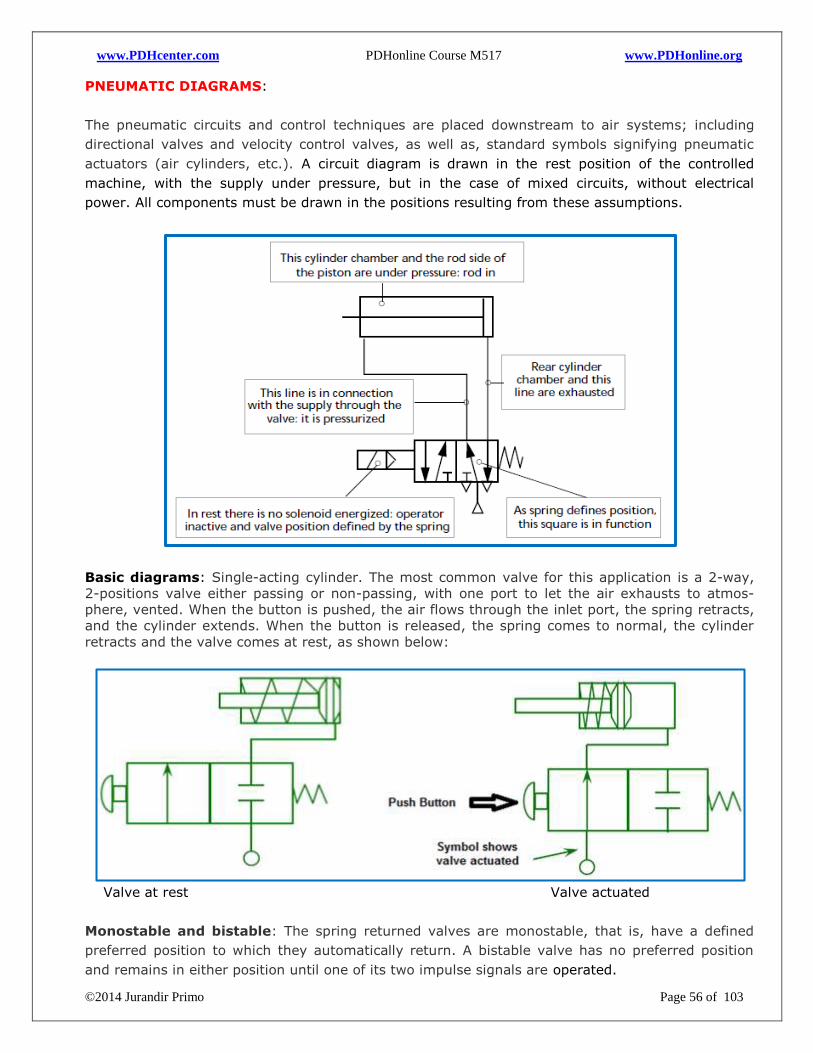
www.PDHcenter.com PDHonline Course M517 www.PDHonline.org
©2014 Jurandir Primo Page 56 of 103
PNEUMATIC DIAGRAMS:
The pneumatic circuits and control techniques are placed downstream to air systems; including
directional valves and velocity control valves, as well as, standard symbols signifying pneumatic
actuators (air cylinders, etc.). A circuit diagram is drawn in the rest position of the controlled
machine, with the supply under pressure, but in the case of mixed circuits, without electrical
power. All components must be drawn in the positions resulting from these assumptions.
Basic diagrams: Single-acting cylinder. The most common valve for this application is a 2-way,
2-positions valve either passing or non-passing, with one port to let the air exhausts to atmos-
phere, vented. When the button is pushed, the air flows through the inlet port, the spring retracts,
and the cylinder extends. When the button is released, the spring comes to normal, the cylinder
retracts and the valve comes at rest, as shown below:
Valve at rest Valve actuated
Monostable and bistable: The spring returned valves are monostable, that is, have a defined
preferred position to which they automatically return. A bistable valve has no preferred position
and remains in either position until one of its two impulse signals are operated.
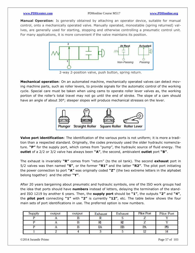
www.PDHcenter.com PDHonline Course M517 www.PDHonline.org
©2014 Jurandir Primo Page 57 of 103
Manual Operation: Is generally obtained by attaching an operator device, suitable for manual
control, onto a mechanically operated valve. Manually operated, monostable (spring returned) val-
lves, are generally used for starting, stopping and otherwise controlling a pneumatic control unit.
For many applications, it is more convenient if the valve maintains its position.
2-way 2-position valve, push button, spring return.
Mechanical operation: On an automated machine, mechanically operated valves can detect mov-
ing machine parts, such as roller levers, to provide signals for the automatic control of the working
cycle. Special care must be taken when using cams to operate roller lever valves as, the working
portion of the roller’s total travel may not go until the end of stroke. The slope of a cam should
have an angle of about 30°; steeper slopes will produce mechanical stresses on the lever.
Valve port identification: The identification of the various ports is not uniform; it is more a tradi-
tion than a respected standard. Originally, the codes previously used the older hydraulic nomencla-
ture. “P” for the supply port, which comes from “pump”, the hydraulic source of fluid energy. The
outlet of a 2/2 or 3/2 valve has always been “A”, the second, ambivalent outlet port “B”.
The exhaust is invariably “R” comes from “return” (to the oil tank). The second exhaust port in
5/2 valves was then named “S”, or the former “R1” and the latter “R2”. The pilot port initiating
the power connection to port “A” was originally coded “Z” (the two extreme letters in the alphabet
belong together) and the other “Y”.
After 20 years bargaining about pneumatic and hydraulic symbols, one of the ISO work groups had
the idea that ports should have numbers instead of letters, delaying the termination of the stand-
ard ISO 1219 by another 6 years. Then, the supply port should be “1”, the outputs “2” and “4”,
the pilot port connecting “1” with “2” is currently “12”, etc. The table below shows the four
main sets of port identifications in use. The preferred option is now numbers.
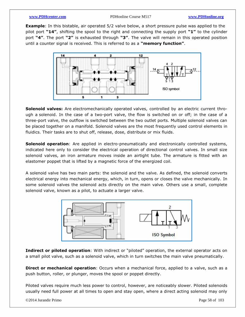
www.PDHcenter.com PDHonline Course M517 www.PDHonline.org
©2014 Jurandir Primo Page 58 of 103
Example: In this bistable, air operated 5/2 valve below, a short pressure pulse was applied to the
pilot port “14”, shifting the spool to the right and connecting the supply port “1” to the cylinder
port “4”. The port “2” is exhausted through “3”. The valve will remain in this operated position
until a counter signal is received. This is referred to as a “memory function”.
Solenoid valves: Are electromechanically operated valves, controlled by an electric current thro-
ugh a solenoid. In the case of a two-port valve, the flow is switched on or off; in the case of a
three-port valve, the outflow is switched between the two outlet ports. Multiple solenoid valves can
be placed together on a manifold. Solenoid valves are the most frequently used control elements in
fluidics. Their tasks are to shut off, release, dose, distribute or mix fluids.
Solenoid operation: Are applied in electro-pneumatically and electronically controlled systems,
indicated here only to consider the electrical operation of directional control valves. In small size
solenoid valves, an iron armature moves inside an airtight tube. The armature is fitted with an
elastomer poppet that is lifted by a magnetic force of the energized coil.
A solenoid valve has two main parts: the solenoid and the valve. As defined, the solenoid converts
electrical energy into mechanical energy, which, in turn, opens or closes the valve mechanically. In
some solenoid valves the solenoid acts directly on the main valve. Others use a small, complete
solenoid valve, known as a pilot, to actuate a larger valve.
Indirect or piloted operation: With indirect or “piloted” operation, the external operator acts on
a small pilot valve, such as a solenoid valve, which in turn switches the main valve pneumatically.
Direct or mechanical operation: Occurs when a mechanical force, applied to a valve, such as a
push button, roller, or plunger, moves the spool or poppet directly.
Piloted valves require much less power to control, however, are noticeably slower. Piloted solenoids
usually need full power at all times to open and stay open, where a direct acting solenoid may only
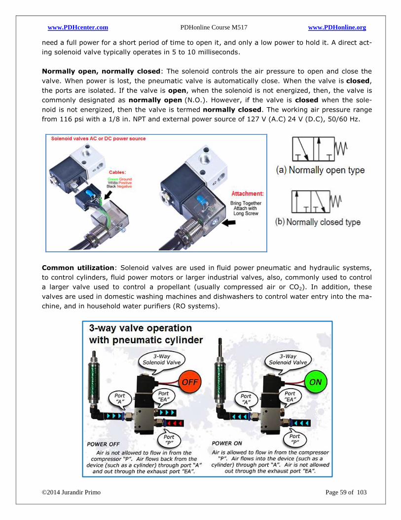
www.PDHcenter.com PDHonline Course M517 www.PDHonline.org
©2014 Jurandir Primo Page 59 of 103
need a full power for a short period of time to open it, and only a low power to hold it. A direct act-
ing solenoid valve typically operates in 5 to 10 milliseconds.
Normally open, normally closed: The solenoid controls the air pressure to open and close the
valve. When power is lost, the pneumatic valve is automatically close. When the valve is closed,
the ports are isolated. If the valve is open, when the solenoid is not energized, then, the valve is
commonly designated as normally open (N.O.). However, if the valve is closed when the sole-
noid is not energized, then the valve is termed normally closed. The working air pressure range
from 116 psi with a 1/8 in. NPT and external power source of 127 V (A.C) 24 V (D.C), 50/60 Hz.
Common utilization: Solenoid valves are used in fluid power pneumatic and hydraulic systems,
to control cylinders, fluid power motors or larger industrial valves, also, commonly used to control
a larger valve used to control a propellant (usually compressed air or CO2). In addition, these
valves are used in domestic washing machines and dishwashers to control water entry into the ma-
chine, and in household water purifiers (RO systems).
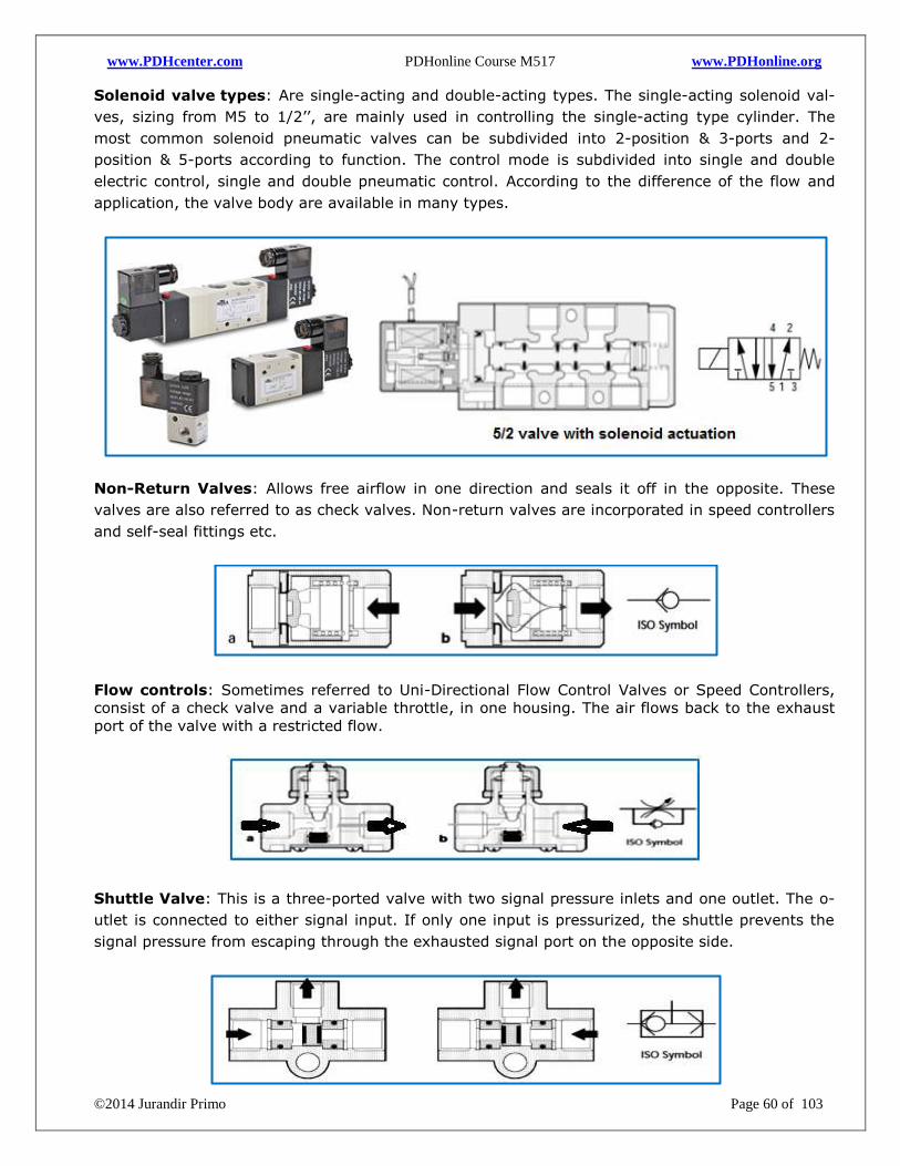
www.PDHcenter.com PDHonline Course M517 www.PDHonline.org
©2014 Jurandir Primo Page 60 of 103
Solenoid valve types: Are single-acting and double-acting types. The single-acting solenoid val-
ves, sizing from M5 to 1/2’’, are mainly used in controlling the single-acting type cylinder. The
most common solenoid pneumatic valves can be subdivided into 2-position & 3-ports and 2-
position & 5-ports according to function. The control mode is subdivided into single and double
electric control, single and double pneumatic control. According to the difference of the flow and
application, the valve body are available in many types.
Non-Return Valves: Allows free airflow in one direction and seals it off in the opposite. These
valves are also referred to as check valves. Non-return valves are incorporated in speed controllers
and self-seal fittings etc.
Flow controls: Sometimes referred to Uni-Directional Flow Control Valves or Speed Controllers,
consist of a check valve and a variable throttle, in one housing. The air flows back to the exhaust
port of the valve with a restricted flow.
Shuttle Valve: This is a three-ported valve with two signal pressure inlets and one outlet. The o-
utlet is connected to either signal input. If only one input is pressurized, the shuttle prevents the
signal pressure from escaping through the exhausted signal port on the opposite side.
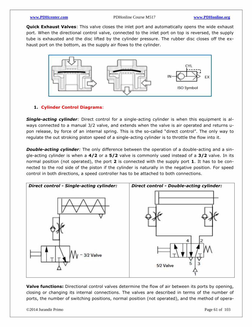
www.PDHcenter.com PDHonline Course M517 www.PDHonline.org
©2014 Jurandir Primo Page 61 of 103
Quick Exhaust Valves: This valve closes the inlet port and automatically opens the wide exhaust
port. When the directional control valve, connected to the inlet port on top is reversed, the supply
tube is exhausted and the disc lifted by the cylinder pressure. The rubber disc closes off the ex-
haust port on the bottom, as the supply air flows to the cylinder.
1. Cylinder Control Diagrams:
Single-acting cylinder: Direct control for a single-acting cylinder is when this equipment is al-
ways connected to a manual 3/2 valve, and extends when the valve is air operated and returns u-
pon release, by force of an internal spring. This is the so-called “direct control”. The only way to
regulate the out stroking piston speed of a single-acting cylinder is to throttle the flow into it.
Double-acting cylinder: The only difference between the operation of a double-acting and a sin-
gle-acting cylinder is when a 4/2 or a 5/2 valve is commonly used instead of a 3/2 valve. In its
normal position (not operated), the port 2 is connected with the supply port 1. It has to be con-
nected to the rod side of the piston if the cylinder is naturally in the negative position. For speed
control in both directions, a speed controller has to be attached to both connections.
Direct control - Single-acting cylinder:
Direct control - Double-acting cylinder:
Valve functions: Directional control valves determine the flow of air between its ports by opening,
closing or changing its internal connections. The valves are described in terms of the number of
ports, the number of switching positions, normal position (not operated), and the method of opera-
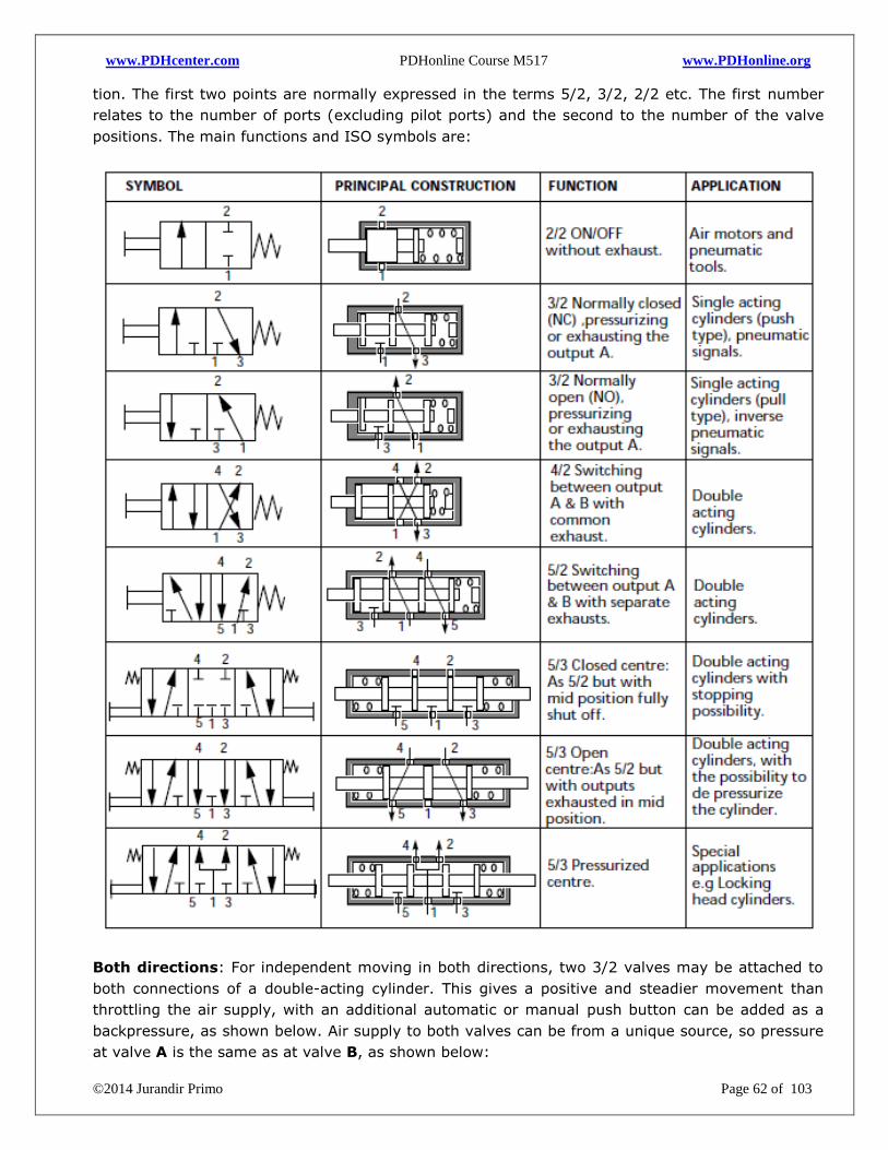
www.PDHcenter.com PDHonline Course M517 www.PDHonline.org
©2014 Jurandir Primo Page 62 of 103
tion. The first two points are normally expressed in the terms 5/2, 3/2, 2/2 etc. The first number
relates to the number of ports (excluding pilot ports) and the second to the number of the valve
positions. The main functions and ISO symbols are:
Both directions: For independent moving in both directions, two 3/2 valves may be attached to
both connections of a double-acting cylinder. This gives a positive and steadier movement than
throttling the air supply, with an additional automatic or manual push button can be added as a
backpressure, as shown below. Air supply to both valves can be from a unique source, so pressure
at valve A is the same as at valve B, as shown below:
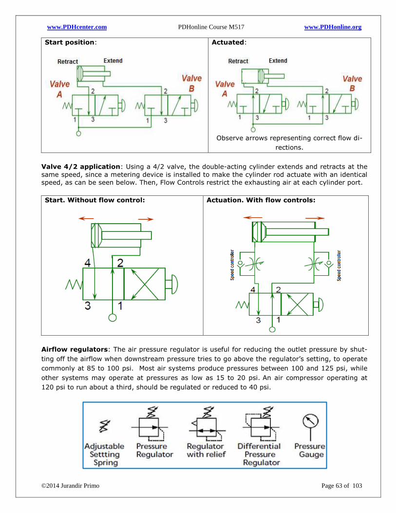
www.PDHcenter.com PDHonline Course M517 www.PDHonline.org
©2014 Jurandir Primo Page 63 of 103
Start position:
Actuated:
Observe arrows representing correct flow di-
rections.
Valve 4/2 application: Using a 4/2 valve, the double-acting cylinder extends and retracts at the
same speed, since a metering device is installed to make the cylinder rod actuate with an identical
speed, as can be seen below. Then, Flow Controls restrict the exhausting air at each cylinder port.
Start. Without flow control:
Actuation. With flow controls:
Airflow regulators: The air pressure regulator is useful for reducing the outlet pressure by shut-
ting off the airflow when downstream pressure tries to go above the regulator’s setting, to operate
commonly at 85 to 100 psi. Most air systems produce pressures between 100 and 125 psi, while
other systems may operate at pressures as low as 15 to 20 psi. An air compressor operating at
120 psi to run about a third, should be regulated or reduced to 40 psi.
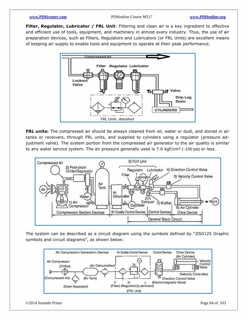
www.PDHcenter.com PDHonline Course M517 www.PDHonline.org
©2014 Jurandir Primo Page 64 of 103
Filter, Regulator, Lubricator / FRL Unit: Filtering and clean air is a key ingredient to effective
and efficient use of tools, equipment, and machinery in almost every industry. Thus, the use of air
preparation devices, such as Filters, Regulators and Lubricators (or FRL Units) are excellent means
of keeping air supply to enable tools and equipment to operate at their peak performance.
FRL units: The compressed air should be always cleaned from oil, water or dust, and stored in air
tanks or receivers, through FRL units, and supplied to cylinders using a regulator (pressure ad-
justment valve). The system portion from the compressed air generator to the air quality is similar
to any water service system. The air pressure generally used is 7.0 kgf/cm² (~100 psi) or less.
The system can be described as a circuit diagram using the symbols defined by "JIS0125 Graphic
symbols and circuit diagrams", as shown below:
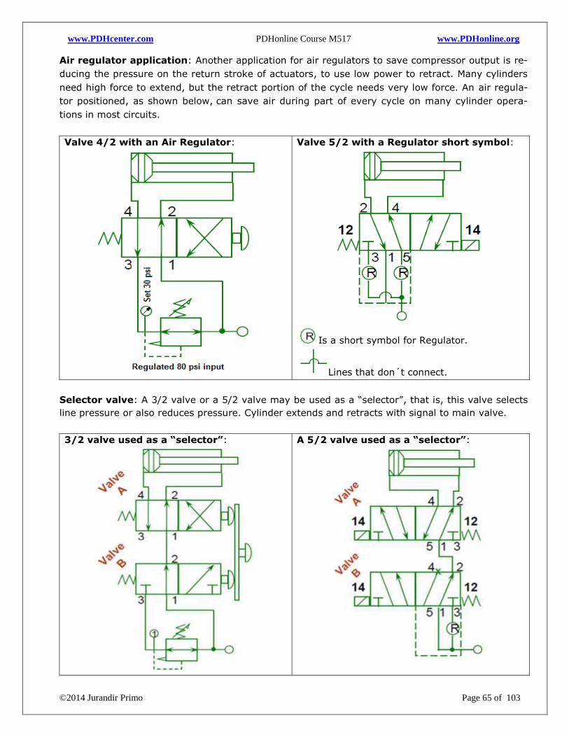
www.PDHcenter.com PDHonline Course M517 www.PDHonline.org
©2014 Jurandir Primo Page 65 of 103
Air regulator application: Another application for air regulators to save compressor output is re-
ducing the pressure on the return stroke of actuators, to use low power to retract. Many cylinders
need high force to extend, but the retract portion of the cycle needs very low force. An air regula-
tor positioned, as shown below, can save air during part of every cycle on many cylinder opera-
tions in most circuits.
Valve 4/2 with an Air Regulator:
Valve 5/2 with a Regulator short symbol:
Is a short symbol for Regulator.
Lines that don´t connect.
Selector valve: A 3/2 valve or a 5/2 valve may be used as a “selector”, that is, this valve selects
line pressure or also reduces pressure. Cylinder extends and retracts with signal to main valve.
3/2 valve used as a “selector”:
A 5/2 valve used as a “selector”:
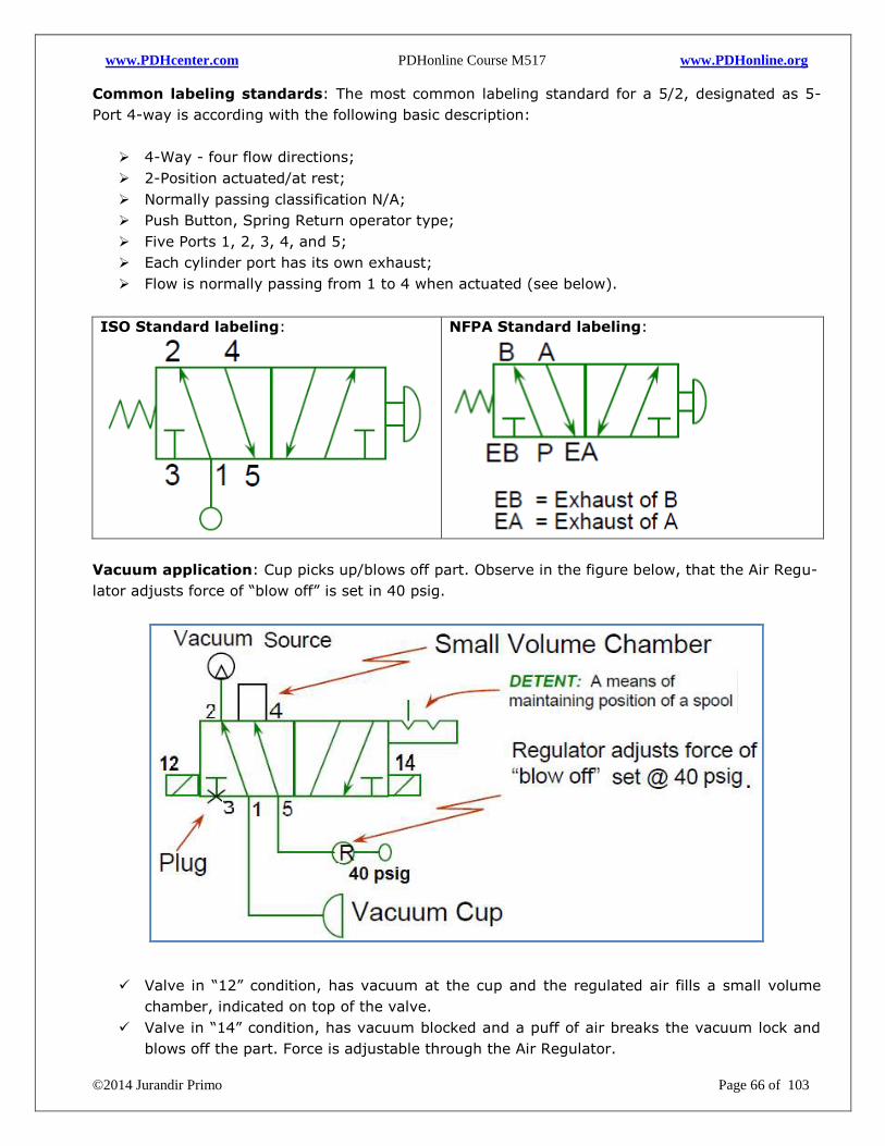
www.PDHcenter.com PDHonline Course M517 www.PDHonline.org
©2014 Jurandir Primo Page 66 of 103
Common labeling standards: The most common labeling standard for a 5/2, designated as 5-
Port 4-way is according with the following basic description:
4-Way - four flow directions;
2-Position actuated/at rest;
Normally passing classification N/A;
Push Button, Spring Return operator type;
Five Ports 1, 2, 3, 4, and 5;
Each cylinder port has its own exhaust;
Flow is normally passing from 1 to 4 when actuated (see below).
ISO Standard labeling:
NFPA Standard labeling:
Vacuum application: Cup picks up/blows off part. Observe in the figure below, that the Air Regu-
lator adjusts force of “blow off” is set in 40 psig.
Valve in “12” condition, has vacuum at the cup and the regulated air fills a small volume
chamber, indicated on top of the valve.
Valve in “14” condition, has vacuum blocked and a puff of air breaks the vacuum lock and
blows off the part. Force is adjustable through the Air Regulator.
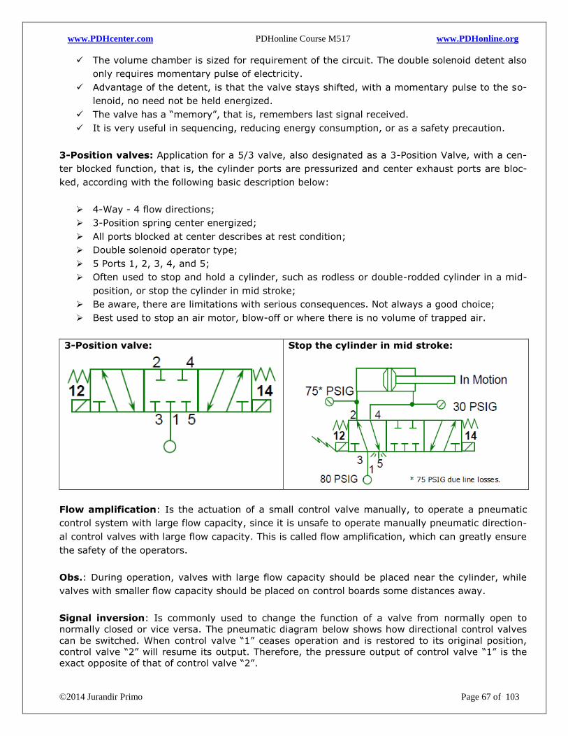
www.PDHcenter.com PDHonline Course M517 www.PDHonline.org
©2014 Jurandir Primo Page 67 of 103
The volume chamber is sized for requirement of the circuit. The double solenoid detent also
only requires momentary pulse of electricity.
Advantage of the detent, is that the valve stays shifted, with a momentary pulse to the so-
lenoid, no need not be held energized.
The valve has a “memory”, that is, remembers last signal received.
It is very useful in sequencing, reducing energy consumption, or as a safety precaution.
3-Position valves: Application for a 5/3 valve, also designated as a 3-Position Valve, with a cen-
ter blocked function, that is, the cylinder ports are pressurized and center exhaust ports are bloc-
ked, according with the following basic description below:
4-Way - 4 flow directions;
3-Position spring center energized;
All ports blocked at center describes at rest condition;
Double solenoid operator type;
5 Ports 1, 2, 3, 4, and 5;
Often used to stop and hold a cylinder, such as rodless or double-rodded cylinder in a mid-
position, or stop the cylinder in mid stroke;
Be aware, there are limitations with serious consequences. Not always a good choice;
Best used to stop an air motor, blow-off or where there is no volume of trapped air.
3-Position valve:
Stop the cylinder in mid stroke:
Flow amplification: Is the actuation of a small control valve manually, to operate a pneumatic
control system with large flow capacity, since it is unsafe to operate manually pneumatic direction-
al control valves with large flow capacity. This is called flow amplification, which can greatly ensure
the safety of the operators.
Obs.: During operation, valves with large flow capacity should be placed near the cylinder, while
valves with smaller flow capacity should be placed on control boards some distances away.
Signal inversion: Is commonly used to change the function of a valve from normally open to
normally closed or vice versa. The pneumatic diagram below shows how directional control valves
can be switched. When control valve “1” ceases operation and is restored to its original position,
control valve “2” will resume its output. Therefore, the pressure output of control valve “1” is the
exact opposite of that of control valve “2”.

www.PDHcenter.com PDHonline Course M517 www.PDHonline.org
©2014 Jurandir Primo Page 68 of 103
Flow amplification:
Signal inversion:
Memory Function: A regular type of function requirement is to perpetuate a momentary valve
operation by holding its signal on, until another signal switches to off. When the control valve “1”
is operated shortly (pressed for a short time), the output signal of the 5/2 directional control valve
“3” will be set to on. The signal will stay that way, until the control valve “2” is operated for a mo-
ment and generates another signal to replace it, causing it to stay permanently.
Selection: Is achieved by converting a 3/2 to a 5/2 function. The start S1 is a 3/2 valve, manually
operated, and the indirectly operated V1 is a 5/2 valve with sufficient flow capacity to operate a
double acting cylinder. One position switches the “green” light indicator, the other switches the red
light. The same function is also used for the selection of two circuits, that is, one of the ports of the
5/2 valve supplies an automatic circuit; the other valves are used for manual control. This makes
sure that no automatic action can take place, during a manual operation.
Memory Function:
Selection:
Delay function: A pneumatic circuit can delay the operating time of the next control valve. The
delay functions can be divided into two classes: On-signal delay and Off-signal delay. Its principle
of operation involves the use of an orifice to slow down the flow of air and control the time of
pneumatic operation.
On-signal delay: When control valve “1” is operated, the one-way flow control valve will
slow the flow of air, thus delaying the signal output of the outlet of control valve “2” (A), re-
sulting in a persistent On-signal. The time when control valve “2” is restored to its original
position is not affected, (see below).
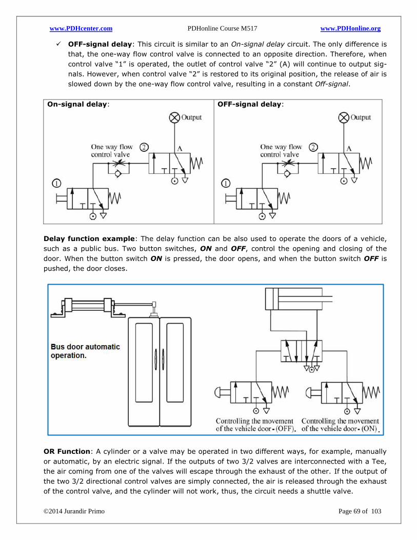
www.PDHcenter.com PDHonline Course M517 www.PDHonline.org
©2014 Jurandir Primo Page 69 of 103
OFF-signal delay: This circuit is similar to an On-signal delay circuit. The only difference is
that, the one-way flow control valve is connected to an opposite direction. Therefore, when
control valve “1” is operated, the outlet of control valve “2” (A) will continue to output sig-
nals. However, when control valve “2” is restored to its original position, the release of air is
slowed down by the one-way flow control valve, resulting in a constant Off-signal.
On-signal delay:
OFF-signal delay:
Delay function example: The delay function can be also used to operate the doors of a vehicle,
such as a public bus. Two button switches, ON and OFF, control the opening and closing of the
door. When the button switch ON is pressed, the door opens, and when the button switch OFF is
pushed, the door closes.
OR Function: A cylinder or a valve may be operated in two different ways, for example, manually
or automatic, by an electric signal. If the outputs of two 3/2 valves are interconnected with a Tee,
the air coming from one of the valves will escape through the exhaust of the other. If the output of
the two 3/2 directional control valves are simply connected, the air is released through the exhaust
of the control valve, and the cylinder will not work, thus, the circuit needs a shuttle valve.
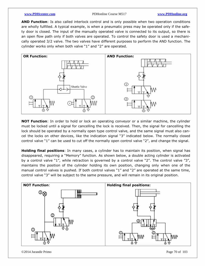
www.PDHcenter.com PDHonline Course M517 www.PDHonline.org
©2014 Jurandir Primo Page 70 of 103
AND Function: Is also called interlock control and is only possible when two operation conditions
are wholly fulfilled. A typical example, is when a pneumatic press may be operated only if the safe-
ty door is closed. The input of the manually operated valve is connected to its output, so there is
an open flow path only if both valves are operated. To control the safety door is used a mechani-
cally operated 3/2 valve. The two valves have different purposes to perform the AND function. The
cylinder works only when both valve “1” and “2” are operated.
OR Function:
AND Function:
NOT Function: In order to hold or lock an operating conveyor or a similar machine, the cylinder
must be locked until a signal for cancelling the lock is received. Then, the signal for cancelling the
lock should be operated by a normally open type control valve, and the same signal must also can-
cel the locks on other devices, like the indication signal “3” indicated below. The normally closed
control valve “1” can be used to cut off the normally open control valve “2”, and change the signal.
Holding final positions: In many cases, a cylinder has to maintain its position, when signal has
disappeared, requiring a “Memory” function. As shown below, a double acting cylinder is activated
by a control valve “1”, while retraction is governed by a control valve “2”. The control valve ”3”,
maintains the position of the cylinder holding its own position, changing only when one of the
manual control valves is pushed. If both control valves “1” and “2” are operated at the same time,
control valve “3” will be subject to the same pressure, and will remain in its original position.
NOT Function:
Holding final positions:
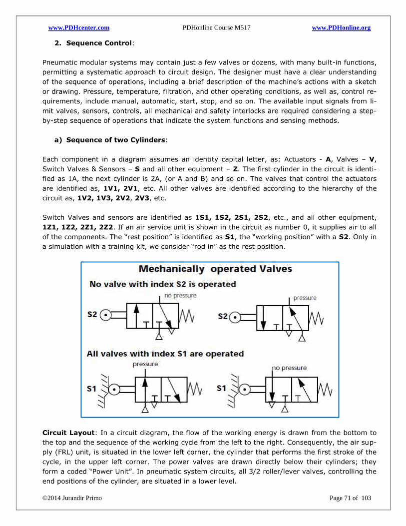
www.PDHcenter.com PDHonline Course M517 www.PDHonline.org
©2014 Jurandir Primo Page 71 of 103
2. Sequence Control:
Pneumatic modular systems may contain just a few valves or dozens, with many built-in functions,
permitting a systematic approach to circuit design. The designer must have a clear understanding
of the sequence of operations, including a brief description of the machine’s actions with a sketch
or drawing. Pressure, temperature, filtration, and other operating conditions, as well as, control re-
quirements, include manual, automatic, start, stop, and so on. The available input signals from li-
mit valves, sensors, controls, all mechanical and safety interlocks are required considering a step-
by-step sequence of operations that indicate the system functions and sensing methods.
a) Sequence of two Cylinders:
Each component in a diagram assumes an identity capital letter, as: Actuators - A, Valves – V,
Switch Valves & Sensors – S and all other equipment – Z. The first cylinder in the circuit is identi-
fied as 1A, the next cylinder is 2A, (or A and B) and so on. The valves that control the actuators
are identified as, 1V1, 2V1, etc. All other valves are identified according to the hierarchy of the
circuit as, 1V2, 1V3, 2V2, 2V3, etc.
Switch Valves and sensors are identified as 1S1, 1S2, 2S1, 2S2, etc., and all other equipment,
1Z1, 1Z2, 2Z1, 2Z2. If an air service unit is shown in the circuit as number 0, it supplies air to all
of the components. The “rest position” is identified as S1, the “working position” with a S2. Only in
a simulation with a training kit, we consider “rod in” as the rest position.
Circuit Layout: In a circuit diagram, the flow of the working energy is drawn from the bottom to
the top and the sequence of the working cycle from the left to the right. Consequently, the air sup-
ply (FRL) unit, is situated in the lower left corner, the cylinder that performs the first stroke of the
cycle, in the upper left corner. The power valves are drawn directly below their cylinders; they
form a coded “Power Unit”. In pneumatic system circuits, all 3/2 roller/lever valves, controlling the
end positions of the cylinder, are situated in a lower level.
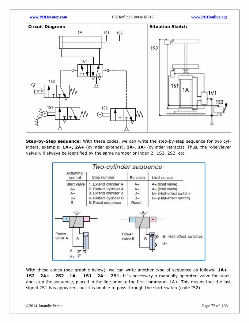
www.PDHcenter.com PDHonline Course M517 www.PDHonline.org
©2014 Jurandir Primo Page 72 of 103
Circuit Diagram:
Situation Sketch:
Step-by-Step sequence: With these codes, we can write the step-by-step sequence for two cyl-
inders, example: 1A+, 2A+ (cylinder extends), 1A-, 2A- (cylinder retracts). Thus, the roller/lever
valve will always be identified by the same number or index 2: 1S2, 2S2, etc.
With these codes (see graphic below), we can write another type of sequence as follows: 1A+ -
1S2 - 2A+ - 2S2 - 1A- - 1S1 - 2A- - 2S1. It´s necessary a manually operated valve for start-
and-stop the sequence, placed in the line prior to the first command, 1A+. This means that the last
signal 2S1 has appeared, but it is unable to pass through the start switch (code IS2).
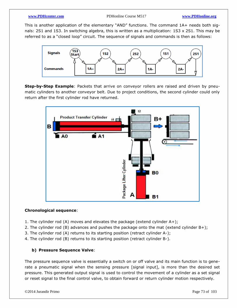
www.PDHcenter.com PDHonline Course M517 www.PDHonline.org
©2014 Jurandir Primo Page 73 of 103
This is another application of the elementary “AND” functions. The command 1A+ needs both sig-
nals: 2S1 and 1S3. In switching algebra, this is written as a multiplication: 1S3 x 2S1. This may be
referred to as a “closed loop” circuit. The sequence of signals and commands is then as follows:
Step-by-Step Example: Packets that arrive on conveyor rollers are raised and driven by pneu-
matic cylinders to another conveyor belt. Due to project conditions, the second cylinder could only
return after the first cylinder rod have returned.
Chronological sequence:
1. The cylinder rod (A) moves and elevates the package (extend cylinder A+);
2. The cylinder rod (B) advances and pushes the package onto the mat (extend cylinder B+);
3. The cylinder rod (A) returns to its starting position (retract cylinder A-);
4. The cylinder rod (B) returns to its starting position (retract cylinder B-).
b) Pressure Sequence Valve:
The pressure sequence valve is essentially a switch on or off valve and its main function is to gene-
rate a pneumatic signal when the sensing pressure [signal input], is more than the desired set
pressure. This generated output signal is used to control the movement of a cylinder as a set signal
or reset signal to the final control valve, to obtain forward or return cylinder motion respectively.
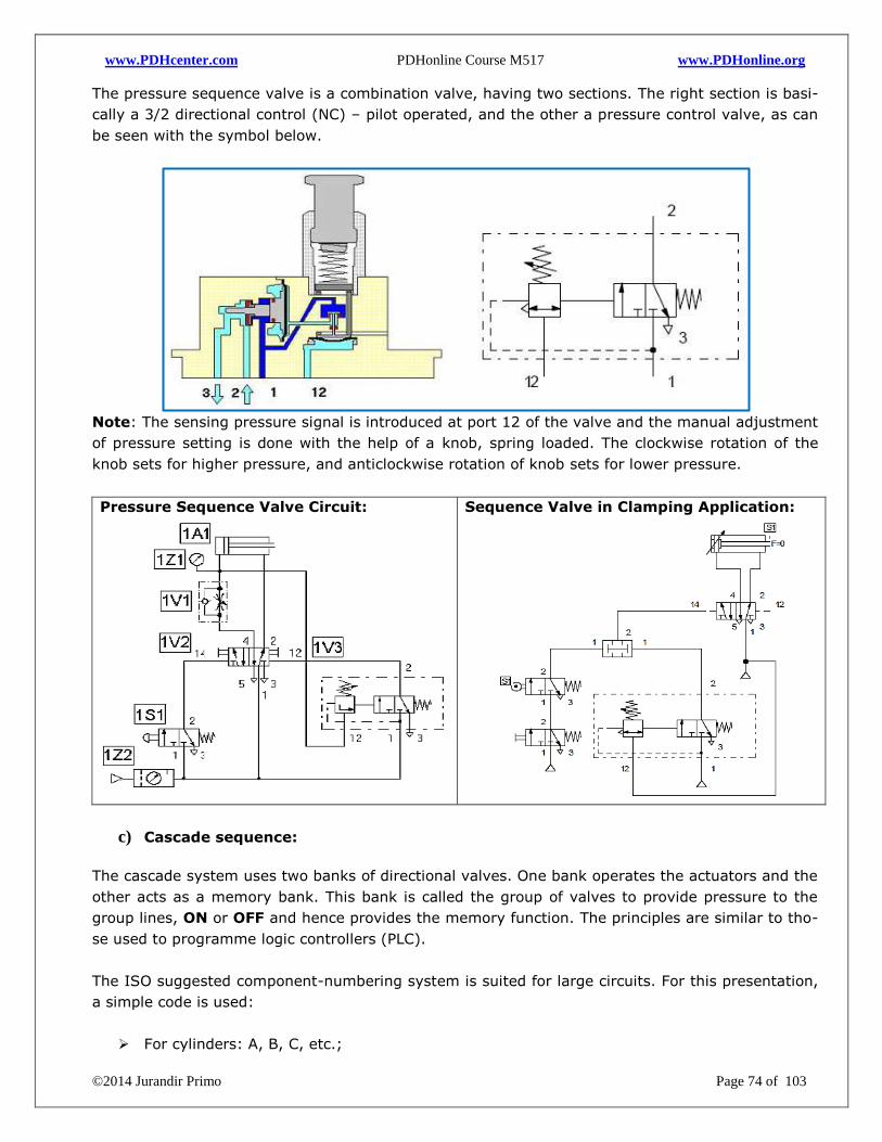
www.PDHcenter.com PDHonline Course M517 www.PDHonline.org
©2014 Jurandir Primo Page 74 of 103
The pressure sequence valve is a combination valve, having two sections. The right section is basi-
cally a 3/2 directional control (NC) – pilot operated, and the other a pressure control valve, as can
be seen with the symbol below.
Note: The sensing pressure signal is introduced at port 12 of the valve and the manual adjustment
of pressure setting is done with the help of a knob, spring loaded. The clockwise rotation of the
knob sets for higher pressure, and anticlockwise rotation of knob sets for lower pressure.
Pressure Sequence Valve Circuit:
Sequence Valve in Clamping Application:
c) Cascade sequence:
The cascade system uses two banks of directional valves. One bank operates the actuators and the
other acts as a memory bank. This bank is called the group of valves to provide pressure to the
group lines, ON or OFF and hence provides the memory function. The principles are similar to tho-
se used to programme logic controllers (PLC).
The ISO suggested component-numbering system is suited for large circuits. For this presentation,
a simple code is used:
For cylinders: A, B, C, etc.;
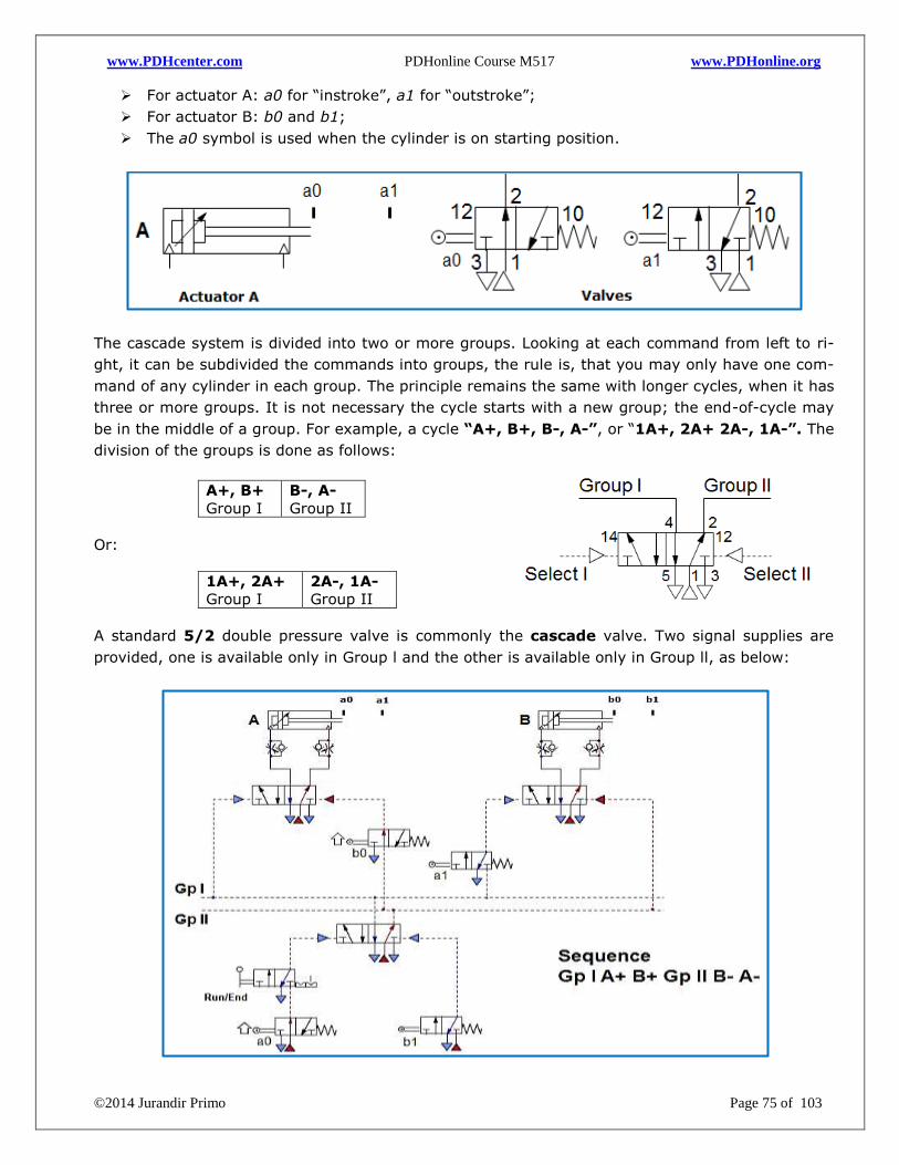
www.PDHcenter.com PDHonline Course M517 www.PDHonline.org
©2014 Jurandir Primo Page 75 of 103
For actuator A: a0 for “instroke”, a1 for “outstroke”;
For actuator B: b0 and b1;
The a0 symbol is used when the cylinder is on starting position.
The cascade system is divided into two or more groups. Looking at each command from left to ri-
ght, it can be subdivided the commands into groups, the rule is, that you may only have one com-
mand of any cylinder in each group. The principle remains the same with longer cycles, when it has
three or more groups. It is not necessary the cycle starts with a new group; the end-of-cycle may
be in the middle of a group. For example, a cycle “A+, B+, B-, A-”, or “1A+, 2A+ 2A-, 1A-”. The
division of the groups is done as follows:
A+, B+
Group I
B-, A-
Group II
Or:
1A+, 2A+
Group I
2A-, 1A-
Group II
A standard 5/2 double pressure valve is commonly the cascade valve. Two signal supplies are
provided, one is available only in Group l and the other is available only in Group ll, as below:
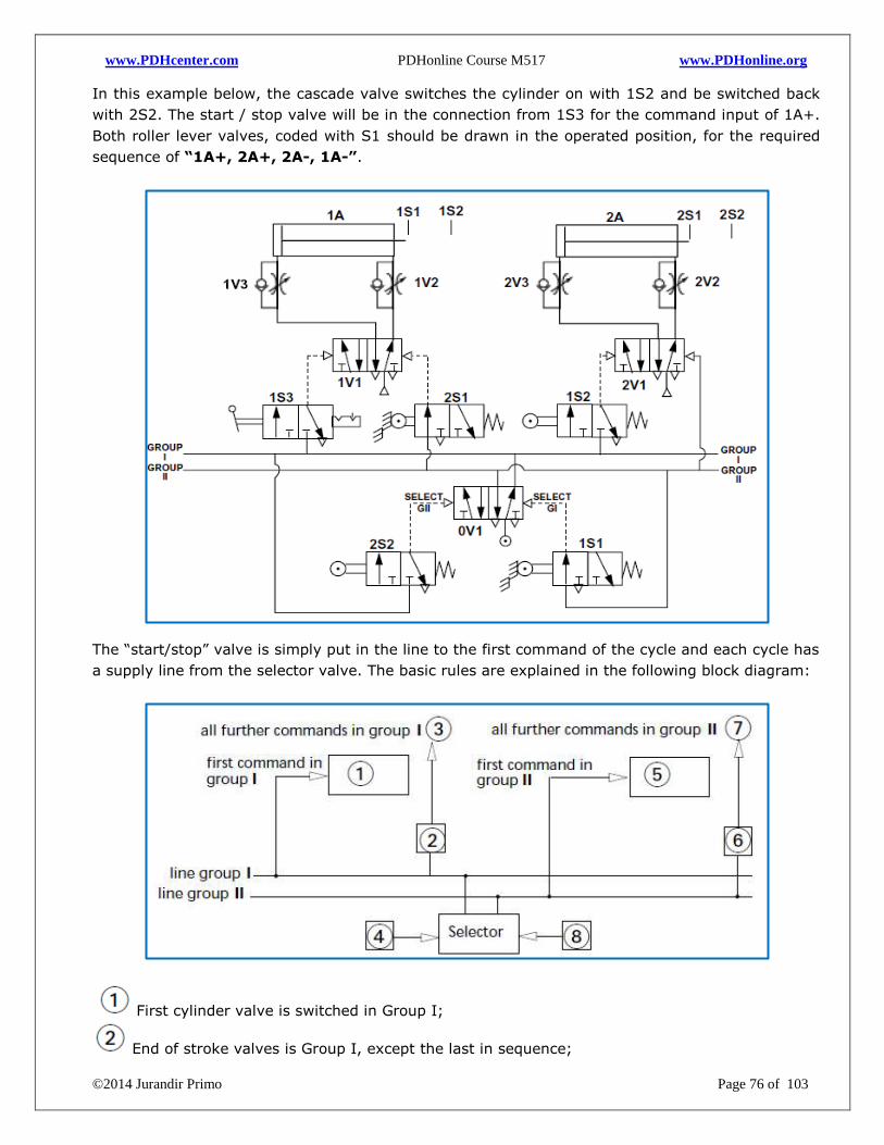
www.PDHcenter.com PDHonline Course M517 www.PDHonline.org
©2014 Jurandir Primo Page 76 of 103
In this example below, the cascade valve switches the cylinder on with 1S2 and be switched back
with 2S2. The start / stop valve will be in the connection from 1S3 for the command input of 1A+.
Both roller lever valves, coded with S1 should be drawn in the operated position, for the required
sequence of “1A+, 2A+, 2A-, 1A-”.
The “start/stop” valve is simply put in the line to the first command of the cycle and each cycle has
a supply line from the selector valve. The basic rules are explained in the following block diagram:
First cylinder valve is switched in Group I;
End of stroke valves is Group I, except the last in sequence;
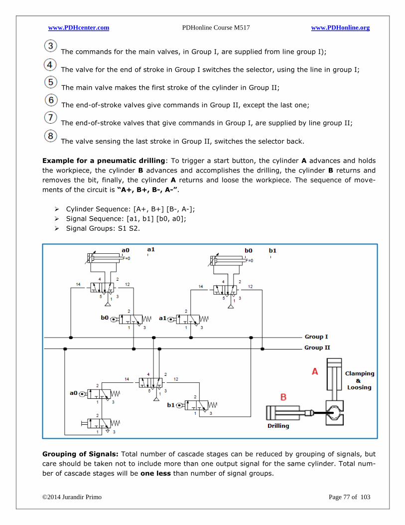
www.PDHcenter.com PDHonline Course M517 www.PDHonline.org
©2014 Jurandir Primo Page 77 of 103
The commands for the main valves, in Group I, are supplied from line group I);
The valve for the end of stroke in Group I switches the selector, using the line in group I;
The main valve makes the first stroke of the cylinder in Group II;
The end-of-stroke valves give commands in Group II, except the last one;
The end-of-stroke valves that give commands in Group I, are supplied by line group II;
The valve sensing the last stroke in Group II, switches the selector back.
Example for a pneumatic drilling: To trigger a start button, the cylinder A advances and holds
the workpiece, the cylinder B advances and accomplishes the drilling, the cylinder B returns and
removes the bit, finally, the cylinder A returns and loose the workpiece. The sequence of move-
ments of the circuit is “A+, B+, B-, A-”.
Cylinder Sequence: [A+, B+] [B-, A-];
Signal Sequence: [a1, b1] [b0, a0];
Signal Groups: S1 S2.
Grouping of Signals: Total number of cascade stages can be reduced by grouping of signals, but
care should be taken not to include more than one output signal for the same cylinder. Total num-
ber of cascade stages will be one less than number of signal groups.
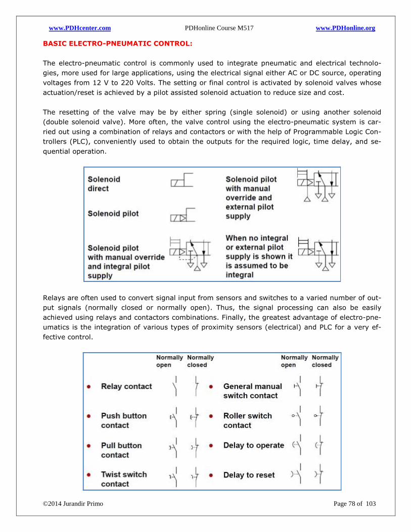
www.PDHcenter.com PDHonline Course M517 www.PDHonline.org
©2014 Jurandir Primo Page 78 of 103
BASIC ELECTRO-PNEUMATIC CONTROL:
The electro-pneumatic control is commonly used to integrate pneumatic and electrical technolo-
gies, more used for large applications, using the electrical signal either AC or DC source, operating
voltages from 12 V to 220 Volts. The setting or final control is activated by solenoid valves whose
actuation/reset is achieved by a pilot assisted solenoid actuation to reduce size and cost.
The resetting of the valve may be by either spring (single solenoid) or using another solenoid
(double solenoid valve). More often, the valve control using the electro-pneumatic system is car-
ried out using a combination of relays and contactors or with the help of Programmable Logic Con-
trollers (PLC), conveniently used to obtain the outputs for the required logic, time delay, and se-
quential operation.
Relays are often used to convert signal input from sensors and switches to a varied number of out-
put signals (normally closed or normally open). Thus, the signal processing can also be easily
achieved using relays and contactors combinations. Finally, the greatest advantage of electro-pne-
umatics is the integration of various types of proximity sensors (electrical) and PLC for a very ef-
fective control.
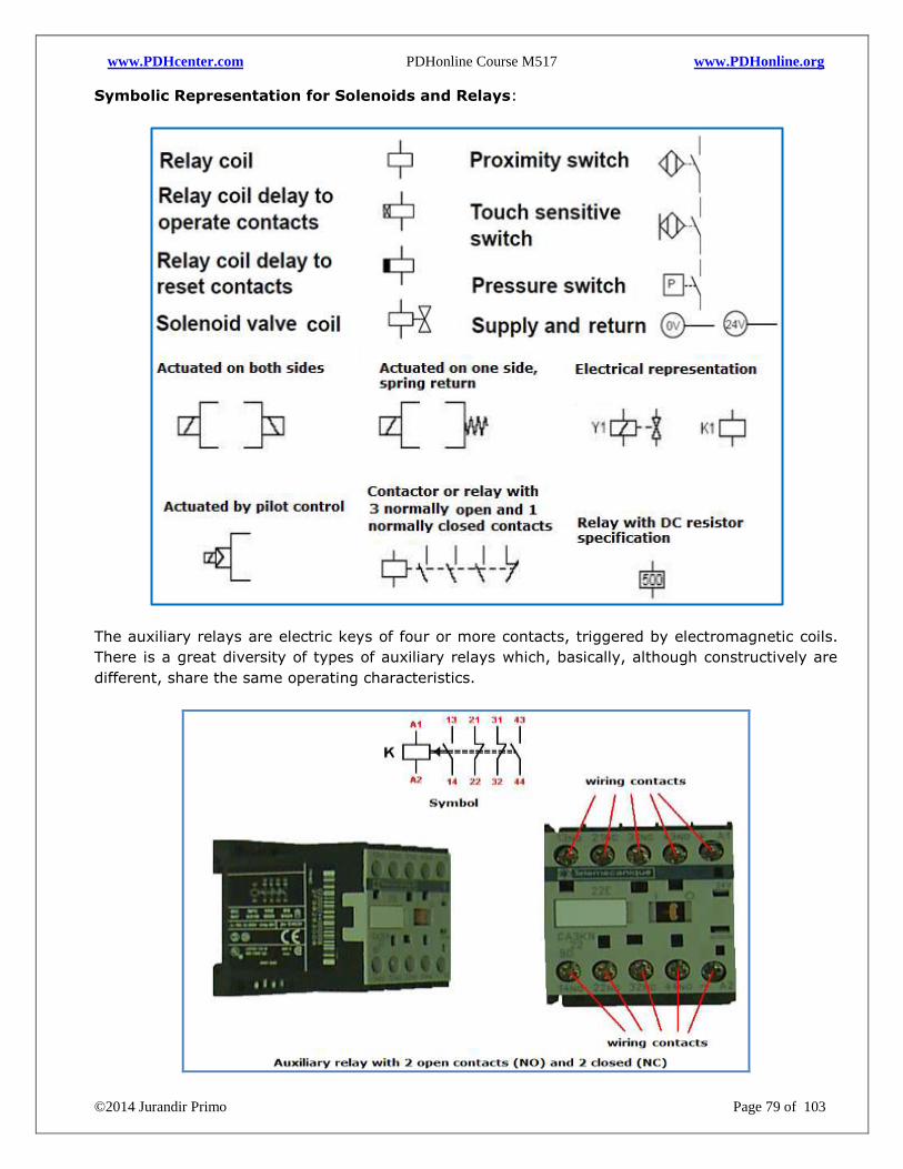
www.PDHcenter.com PDHonline Course M517 www.PDHonline.org
©2014 Jurandir Primo Page 79 of 103
Symbolic Representation for Solenoids and Relays:
The auxiliary relays are electric keys of four or more contacts, triggered by electromagnetic coils.
There is a great diversity of types of auxiliary relays which, basically, although constructively are
different, share the same operating characteristics.
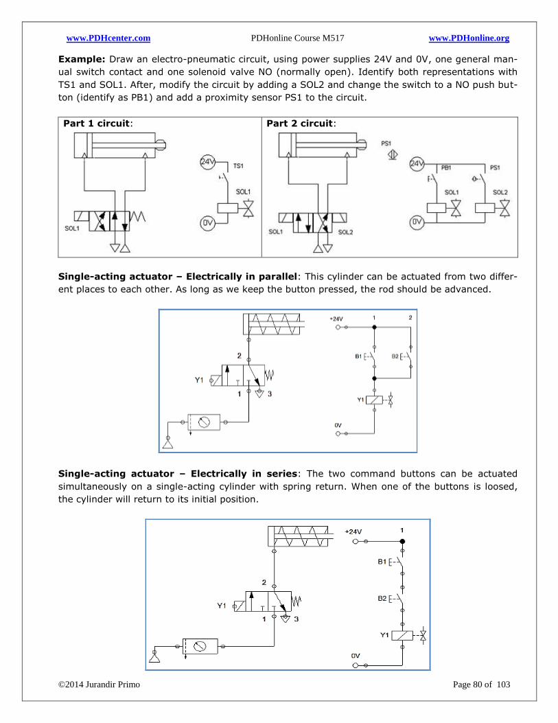
www.PDHcenter.com PDHonline Course M517 www.PDHonline.org
©2014 Jurandir Primo Page 80 of 103
Example: Draw an electro-pneumatic circuit, using power supplies 24V and 0V, one general man-
ual switch contact and one solenoid valve NO (normally open). Identify both representations with
TS1 and SOL1. After, modify the circuit by adding a SOL2 and change the switch to a NO push but-
ton (identify as PB1) and add a proximity sensor PS1 to the circuit.
Part 1 circuit:
Part 2 circuit:
Single-acting actuator – Electrically in parallel: This cylinder can be actuated from two differ-
ent places to each other. As long as we keep the button pressed, the rod should be advanced.
Single-acting actuator – Electrically in series: The two command buttons can be actuated
simultaneously on a single-acting cylinder with spring return. When one of the buttons is loosed,
the cylinder will return to its initial position.
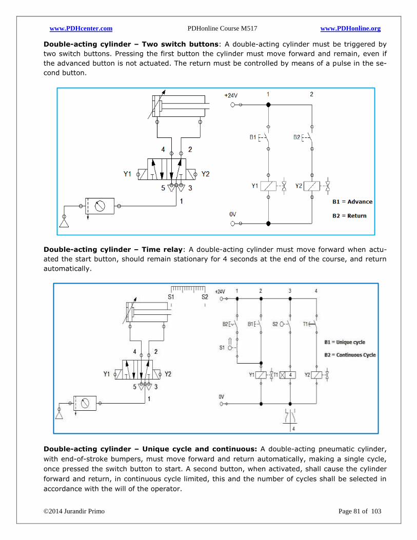
www.PDHcenter.com PDHonline Course M517 www.PDHonline.org
©2014 Jurandir Primo Page 81 of 103
Double-acting cylinder – Two switch buttons: A double-acting cylinder must be triggered by
two switch buttons. Pressing the first button the cylinder must move forward and remain, even if
the advanced button is not actuated. The return must be controlled by means of a pulse in the se-
cond button.
Double-acting cylinder – Time relay: A double-acting cylinder must move forward when actu-
ated the start button, should remain stationary for 4 seconds at the end of the course, and return
automatically.
Double-acting cylinder – Unique cycle and continuous: A double-acting pneumatic cylinder,
with end-of-stroke bumpers, must move forward and return automatically, making a single cycle,
once pressed the switch button to start. A second button, when activated, shall cause the cylinder
forward and return, in continuous cycle limited, this and the number of cycles shall be selected in
accordance with the will of the operator.
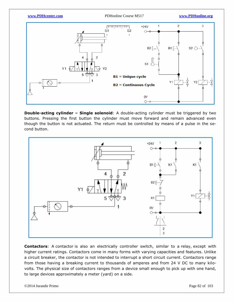
www.PDHcenter.com PDHonline Course M517 www.PDHonline.org
©2014 Jurandir Primo Page 82 of 103
Double-acting cylinder – Single solenoid: A double-acting cylinder must be triggered by two
buttons. Pressing the first button the cylinder must move forward and remain advanced even
though the button is not actuated. The return must be controlled by means of a pulse in the se-
cond button.
Contactors: A contactor is also an electrically controller switch, similar to a relay, except with
higher current ratings. Contactors come in many forms with varying capacities and features. Unlike
a circuit breaker, the contactor is not intended to interrupt a short circuit current. Contactors range
from those having a breaking current to thousands of amperes and from 24 V DC to many kilo-
volts. The physical size of contactors ranges from a device small enough to pick up with one hand,
to large devices approximately a meter (yard) on a side.
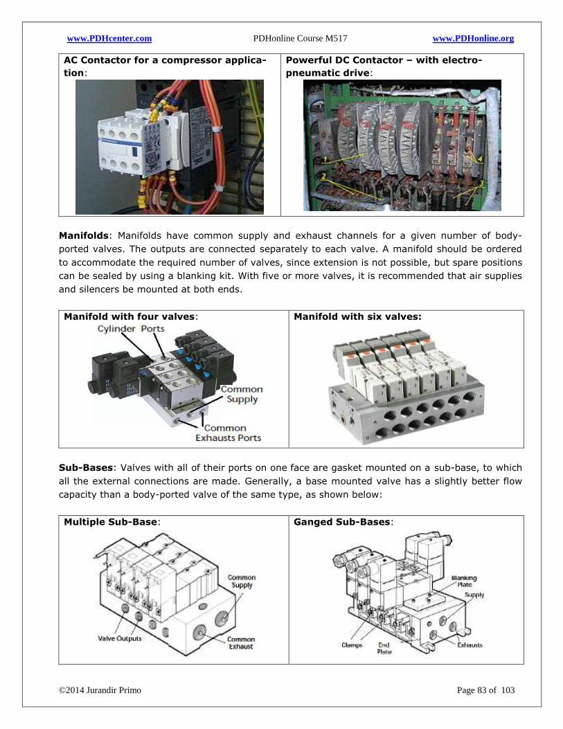
www.PDHcenter.com PDHonline Course M517 www.PDHonline.org
©2014 Jurandir Primo Page 83 of 103
AC Contactor for a compressor applica-
tion:
Powerful DC Contactor – with electro-
pneumatic drive:
Manifolds: Manifolds have common supply and exhaust channels for a given number of body-
ported valves. The outputs are connected separately to each valve. A manifold should be ordered
to accommodate the required number of valves, since extension is not possible, but spare positions
can be sealed by using a blanking kit. With five or more valves, it is recommended that air supplies
and silencers be mounted at both ends.
Manifold with four valves:
Manifold with six valves:
Sub-Bases: Valves with all of their ports on one face are gasket mounted on a sub-base, to which
all the external connections are made. Generally, a base mounted valve has a slightly better flow
capacity than a body-ported valve of the same type, as shown below:
Multiple Sub-Base:
Ganged Sub-Bases:
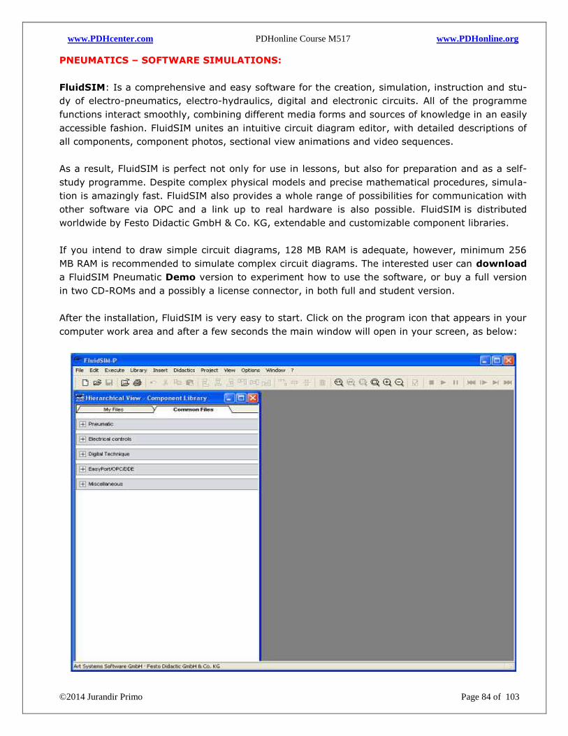
www.PDHcenter.com PDHonline Course M517 www.PDHonline.org
©2014 Jurandir Primo Page 84 of 103
PNEUMATICS – SOFTWARE SIMULATIONS:
FluidSIM: Is a comprehensive and easy software for the creation, simulation, instruction and stu-
dy of electro-pneumatics, electro-hydraulics, digital and electronic circuits. All of the programme
functions interact smoothly, combining different media forms and sources of knowledge in an easily
accessible fashion. FluidSIM unites an intuitive circuit diagram editor, with detailed descriptions of
all components, component photos, sectional view animations and video sequences.
As a result, FluidSIM is perfect not only for use in lessons, but also for preparation and as a self-
study programme. Despite complex physical models and precise mathematical procedures, simula-
tion is amazingly fast. FluidSIM also provides a whole range of possibilities for communication with
other software via OPC and a link up to real hardware is also possible. FluidSIM is distributed
worldwide by Festo Didactic GmbH & Co. KG, extendable and customizable component libraries.
If you intend to draw simple circuit diagrams, 128 MB RAM is adequate, however, minimum 256
MB RAM is recommended to simulate complex circuit diagrams. The interested user can download
a FluidSIM Pneumatic Demo version to experiment how to use the software, or buy a full version
in two CD-ROMs and a possibly a license connector, in both full and student version.
After the installation, FluidSIM is very easy to start. Click on the program icon that appears in your
computer work area and after a few seconds the main window will open in your screen, as below:
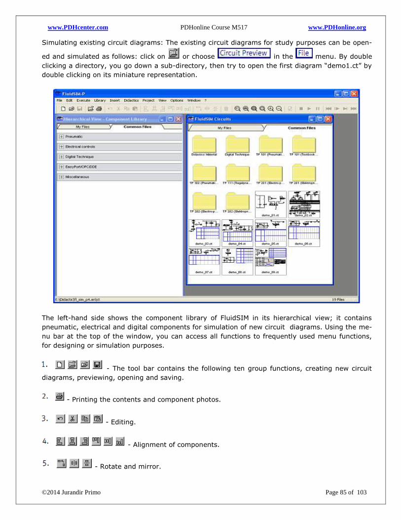
www.PDHcenter.com PDHonline Course M517 www.PDHonline.org
©2014 Jurandir Primo Page 85 of 103
Simulating existing circuit diagrams: The existing circuit diagrams for study purposes can be open-
ed and simulated as follows: click on or choose in the menu. By double
clicking a directory, you go down a sub-directory, then try to open the first diagram “demo1.ct” by
double clicking on its miniature representation.
The left-hand side shows the component library of FluidSIM in its hierarchical view; it contains
pneumatic, electrical and digital components for simulation of new circuit diagrams. Using the me-
nu bar at the top of the window, you can access all functions to frequently used menu functions,
for designing or simulation purposes.
- The tool bar contains the following ten group functions, creating new circuit
diagrams, previewing, opening and saving.
- Printing the contents and component photos.
- Editing.
- Alignment of components.
- Rotate and mirror.
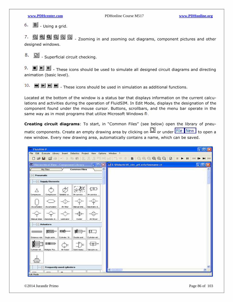
www.PDHcenter.com PDHonline Course M517 www.PDHonline.org
©2014 Jurandir Primo Page 86 of 103
- Using a grid.
- Zooming in and zooming out diagrams, component pictures and other
designed windows.
- Superficial circuit checking.
- These icons should be used to simulate all designed circuit diagrams and directing
animation (basic level).
- These icons should be used in simulation as additional functions.
Located at the bottom of the window is a status bar that displays information on the current calcu-
lations and activities during the operation of FluidSIM. In Edit Mode, displays the designation of the
component found under the mouse cursor. Buttons, scrollbars, and the menu bar operate in the
same way as in most programs that utilize Microsoft Windows .
Creating circuit diagrams: To start, in “Common Files” (see below) open the library of pneu-
matic components. Create an empty drawing area by clicking on or under to open a
new window. Every new drawing area, automatically contains a name, which can be saved.
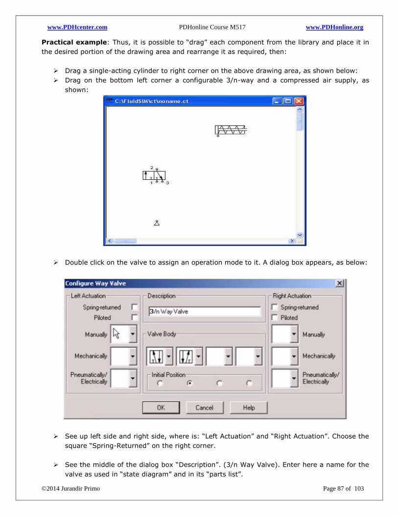
www.PDHcenter.com PDHonline Course M517 www.PDHonline.org
©2014 Jurandir Primo Page 87 of 103
Practical example: Thus, it is possible to “drag” each component from the library and place it in
the desired portion of the drawing area and rearrange it as required, then:
Drag a single-acting cylinder to right corner on the above drawing area, as shown below:
Drag on the bottom left corner a configurable 3/n-way and a compressed air supply, as
shown:
Double click on the valve to assign an operation mode to it. A dialog box appears, as below:
See up left side and right side, where is: “Left Actuation” and “Right Actuation”. Choose the
square “Spring-Returned” on the right corner.
See the middle of the dialog box “Description”. (3/n Way Valve). Enter here a name for the
valve as used in “state diagram” and in its “parts list”.
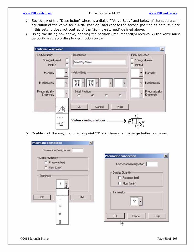
www.PDHcenter.com PDHonline Course M517 www.PDHonline.org
©2014 Jurandir Primo Page 88 of 103
See below of the “Description” where is a dialog “”Valve Body” and below of the square con-
figuration of the valve see “Initial Position” and choose the second position as default, since
if this setting does not contradict the “Spring-returned” defined above.
Using the dialog box above, opening the position (Pneumatically/Electrically) the valve must
be configured according to description below:
Double click the way identified as point “3” and choose a discharge buffer, as below:
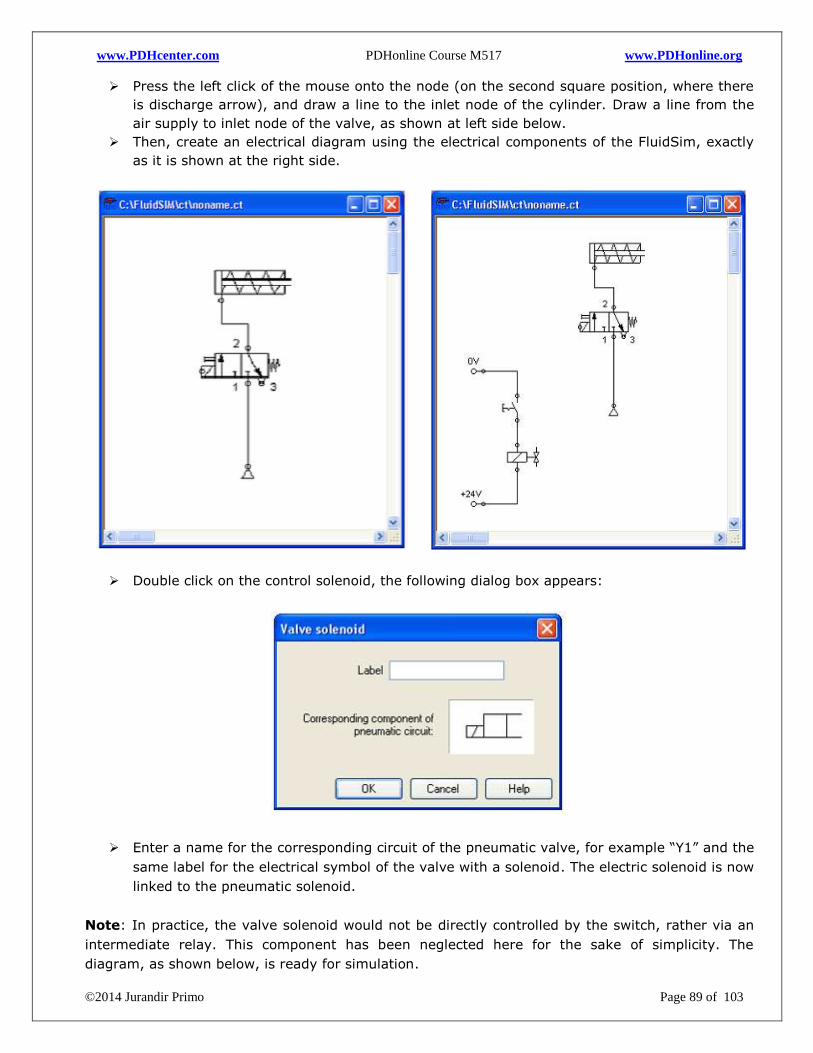
www.PDHcenter.com PDHonline Course M517 www.PDHonline.org
©2014 Jurandir Primo Page 89 of 103
Press the left click of the mouse onto the node (on the second square position, where there
is discharge arrow), and draw a line to the inlet node of the cylinder. Draw a line from the
air supply to inlet node of the valve, as shown at left side below.
Then, create an electrical diagram using the electrical components of the FluidSim, exactly
as it is shown at the right side.
Double click on the control solenoid, the following dialog box appears:
Enter a name for the corresponding circuit of the pneumatic valve, for example “Y1” and the
same label for the electrical symbol of the valve with a solenoid. The electric solenoid is now
linked to the pneumatic solenoid.
Note: In practice, the valve solenoid would not be directly controlled by the switch, rather via an
intermediate relay. This component has been neglected here for the sake of simplicity. The
diagram, as shown below, is ready for simulation.
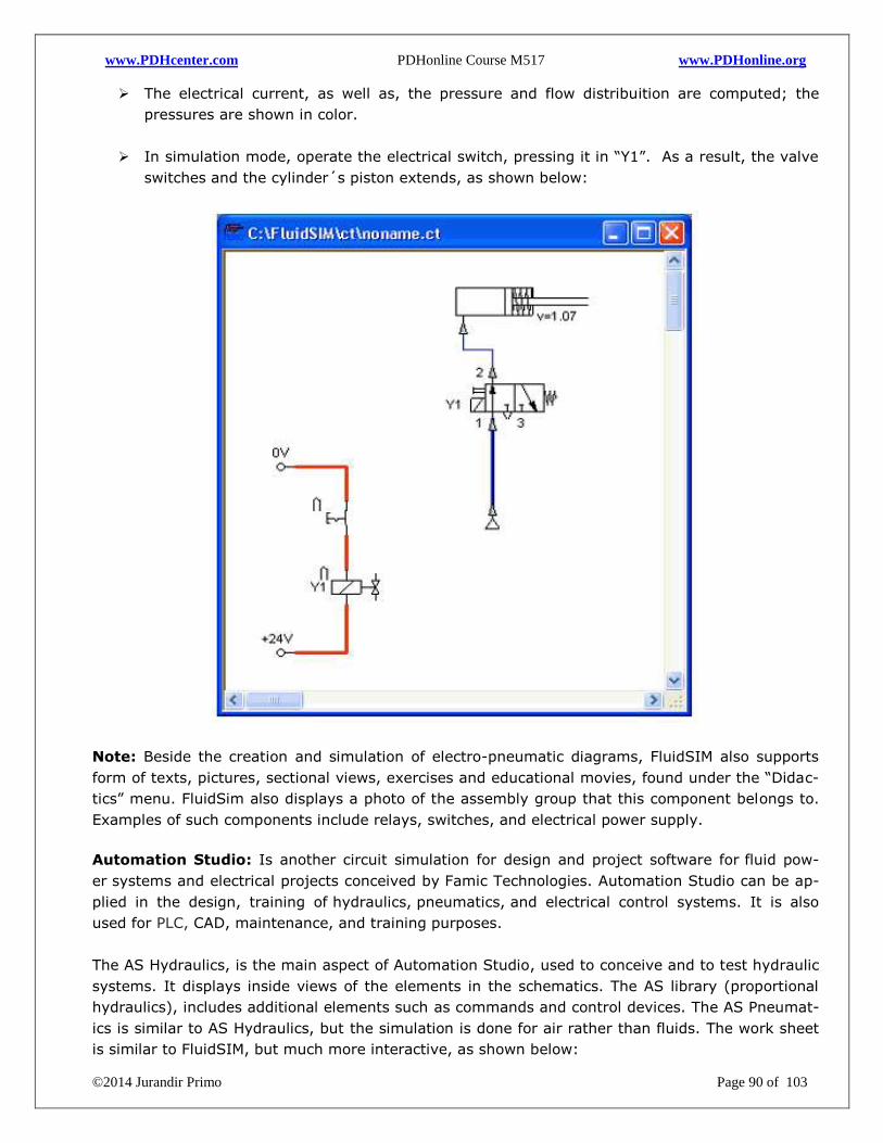
www.PDHcenter.com PDHonline Course M517 www.PDHonline.org
©2014 Jurandir Primo Page 90 of 103
The electrical current, as well as, the pressure and flow distribuition are computed; the
pressures are shown in color.
In simulation mode, operate the electrical switch, pressing it in “Y1”. As a result, the valve
switches and the cylinder´s piston extends, as shown below:
Note: Beside the creation and simulation of electro-pneumatic diagrams, FluidSIM also supports
form of texts, pictures, sectional views, exercises and educational movies, found under the “Didac-
tics” menu. FluidSim also displays a photo of the assembly group that this component belongs to.
Examples of such components include relays, switches, and electrical power supply.
Automation Studio: Is another circuit simulation for design and project software for fluid pow-
er systems and electrical projects conceived by Famic Technologies. Automation Studio can be ap-
plied in the design, training of hydraulics, pneumatics, and electrical control systems. It is also
used for PLC, CAD, maintenance, and training purposes.
The AS Hydraulics, is the main aspect of Automation Studio, used to conceive and to test hydraulic
systems. It displays inside views of the elements in the schematics. The AS library (proportional
hydraulics), includes additional elements such as commands and control devices. The AS Pneumat-
ics is similar to AS Hydraulics, but the simulation is done for air rather than fluids. The work sheet
is similar to FluidSIM, but much more interactive, as shown below:
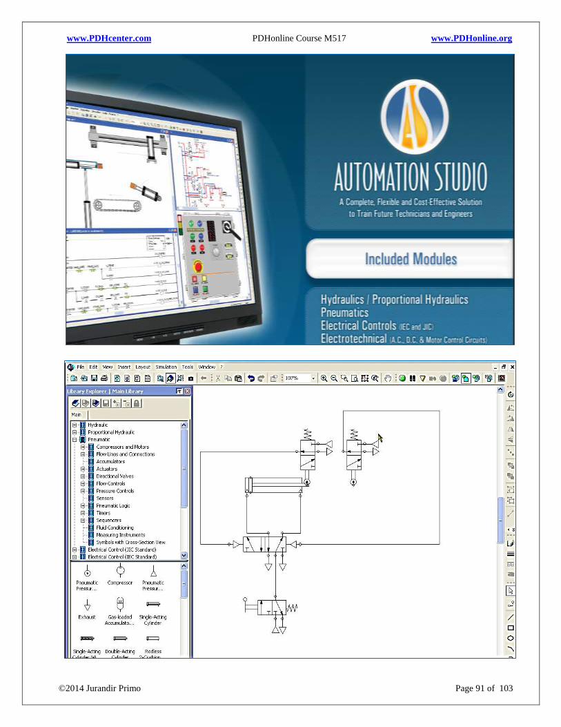
www.PDHcenter.com PDHonline Course M517 www.PDHonline.org
©2014 Jurandir Primo Page 91 of 103
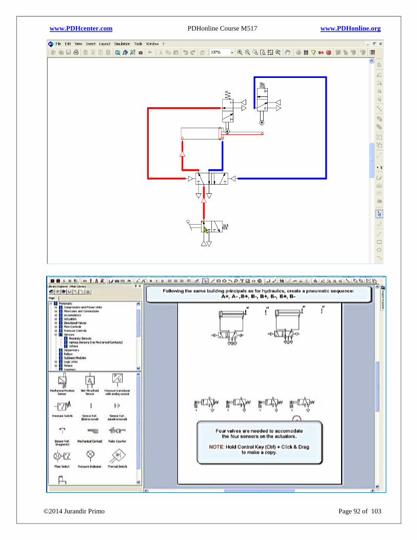
www.PDHcenter.com PDHonline Course M517 www.PDHonline.org
©2014 Jurandir Primo Page 92 of 103
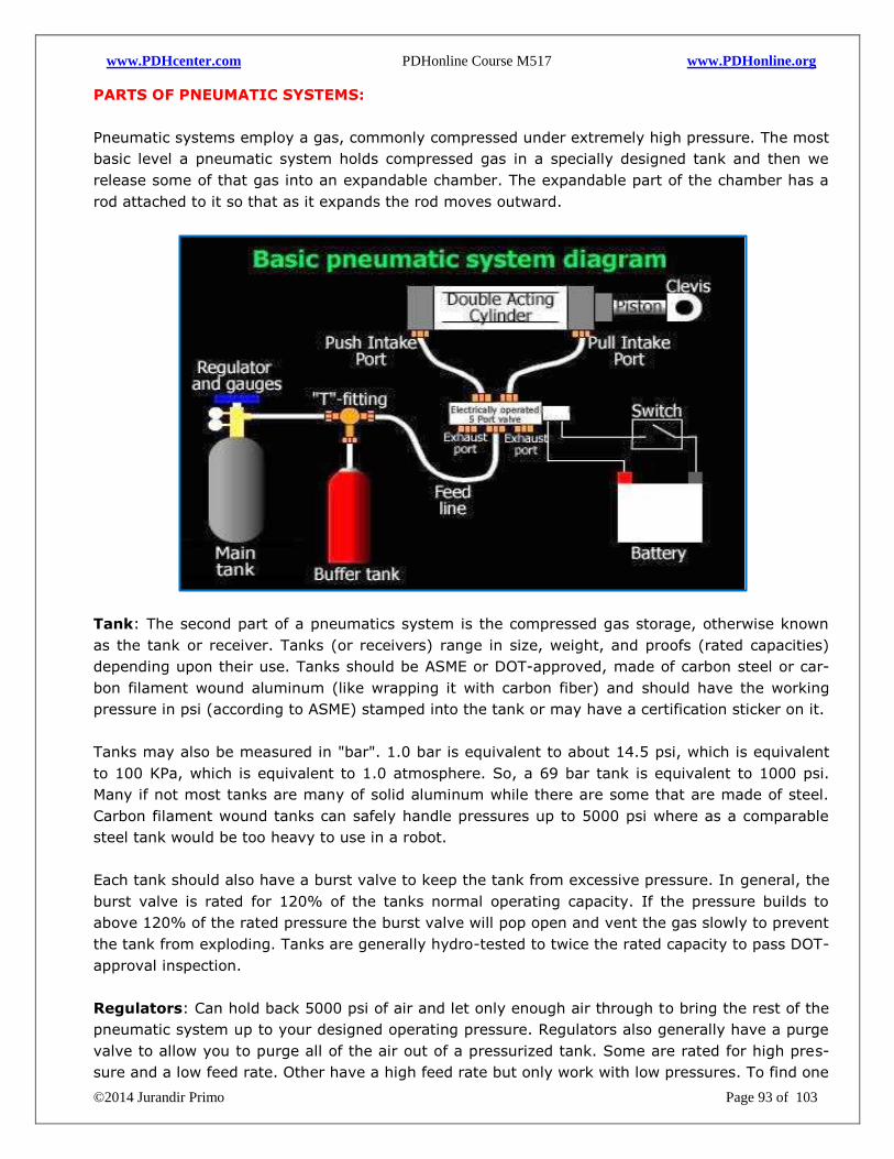
www.PDHcenter.com PDHonline Course M517 www.PDHonline.org
©2014 Jurandir Primo Page 93 of 103
PARTS OF PNEUMATIC SYSTEMS:
Pneumatic systems employ a gas, commonly compressed under extremely high pressure. The most
basic level a pneumatic system holds compressed gas in a specially designed tank and then we
release some of that gas into an expandable chamber. The expandable part of the chamber has a
rod attached to it so that as it expands the rod moves outward.
Tank: The second part of a pneumatics system is the compressed gas storage, otherwise known
as the tank or receiver. Tanks (or receivers) range in size, weight, and proofs (rated capacities)
depending upon their use. Tanks should be ASME or DOT-approved, made of carbon steel or car-
bon filament wound aluminum (like wrapping it with carbon fiber) and should have the working
pressure in psi (according to ASME) stamped into the tank or may have a certification sticker on it.
Tanks may also be measured in "bar". 1.0 bar is equivalent to about 14.5 psi, which is equivalent
to 100 KPa, which is equivalent to 1.0 atmosphere. So, a 69 bar tank is equivalent to 1000 psi.
Many if not most tanks are many of solid aluminum while there are some that are made of steel.
Carbon filament wound tanks can safely handle pressures up to 5000 psi where as a comparable
steel tank would be too heavy to use in a robot.
Each tank should also have a burst valve to keep the tank from excessive pressure. In general, the
burst valve is rated for 120% of the tanks normal operating capacity. If the pressure builds to
above 120% of the rated pressure the burst valve will pop open and vent the gas slowly to prevent
the tank from exploding. Tanks are generally hydro-tested to twice the rated capacity to pass DOT-
approval inspection.
Regulators: Can hold back 5000 psi of air and let only enough air through to bring the rest of the
pneumatic system up to your designed operating pressure. Regulators also generally have a purge
valve to allow you to purge all of the air out of a pressurized tank. Some are rated for high pres-
sure and a low feed rate. Other have a high feed rate but only work with low pressures. To find one
www.PDHcenter.com PDHonline Course M517 www.PDHonline.org
©2014 Jurandir Primo Page 94 of 103
that has a high feed rate and can handle high pressure is tough and usually expensive. Some regu-
lators will already have gauges to show tank pressure and another to show regulated pressure.
Knowing both of these is crucial and in some cases mandatory on your robot.
Note: You should always have a way to bleed the system of pressurized air on BOTH sides of the
regulator, usually by means of a manually operated purge valve. You never want to get parts of
your body near a fully pressurized system.
Buffer tanks: Are not necessarily part of every pneumatic system. A buffer tank is just an extra
tank in between your regulator and your valve that stores extra gas. As an example, a pneumatic
cylinder that has a 4-inch bore and a 6-inch stroke, gives us a total of about 75 cubic inches. Thus,
1/2" pneumatic tubing between a regulator, a valve and on to the cylinder uses 250 psi of CO2.
Then, 24" of total tubing has almost 5 cubic inches of compressed air in the feed lines. That will
move the piston about half an inch before the regulator has to start feeding more air into chamber.
When you fire the valves, the buffer tank dumps its 75 cubic inches of compressed air with the 5
cubic inches that was already in the lines. The full 250 psi that is sitting in the buffer tank and the
feed lines does not fill the cylinder instantly. What actually happens is the split second the valves
open up is that the system equalizes pressure until the regulator can catch up and bring it up to
the full 250 psi.
Pneumatic hoses and fittings:
To get the best airflow is necessary to use the largest diameter hose is rated for the pressures to
be used and find matching connectors and fittings throughout the system. It does no good to have
1/2" hoses and fittings throughout your whole system only to have a 1/8" port on your solenoid
valves. The 'push to connect' low pressure fittings and hoses are the easiest to work with for proto-
typing and low pressures.
Hydraulic lines and fittings are designed for extremely high pressure and are sometimes sheathed
with a steel mesh to help keep the hose from deforming and developing bubbles. Hydraulic compo-
nents are usually metal-to-metal fittings, usually enough to keep a liquid restrained but not neces-
sarily a gas (meaning it is not 'bubble tight'). It is also necessary PTFE tape on all threaded con-
nections as it helps seal any gaps that may occur between the threads. Other miscellaneous things
that you may need on your system are a shut off valve and a bleed valve.
Valves: The valve will probably be the most critical (and consequently the most expensive) part of
a high power pneumatics system. It has to restrain the pressure built up on one side and be able
to 'pop' completely open and not restrict the air as it rushes through on its way to the cylinder.
There are many types of valves that can be used; remotely operated, manually operated, and so-
lenoid valves.
The reason that it is called a 'solenoid valve' is because there are two parts; the valve and the
solenoid that activates the valve. The solenoid opens a smaller valve that controls a small stream
of air that that pops open the large high flow valve. There are several different types of solenoid
valves, but the three most common ones used in robots, are the 3-port, 4-port, and the 5-port
valve.
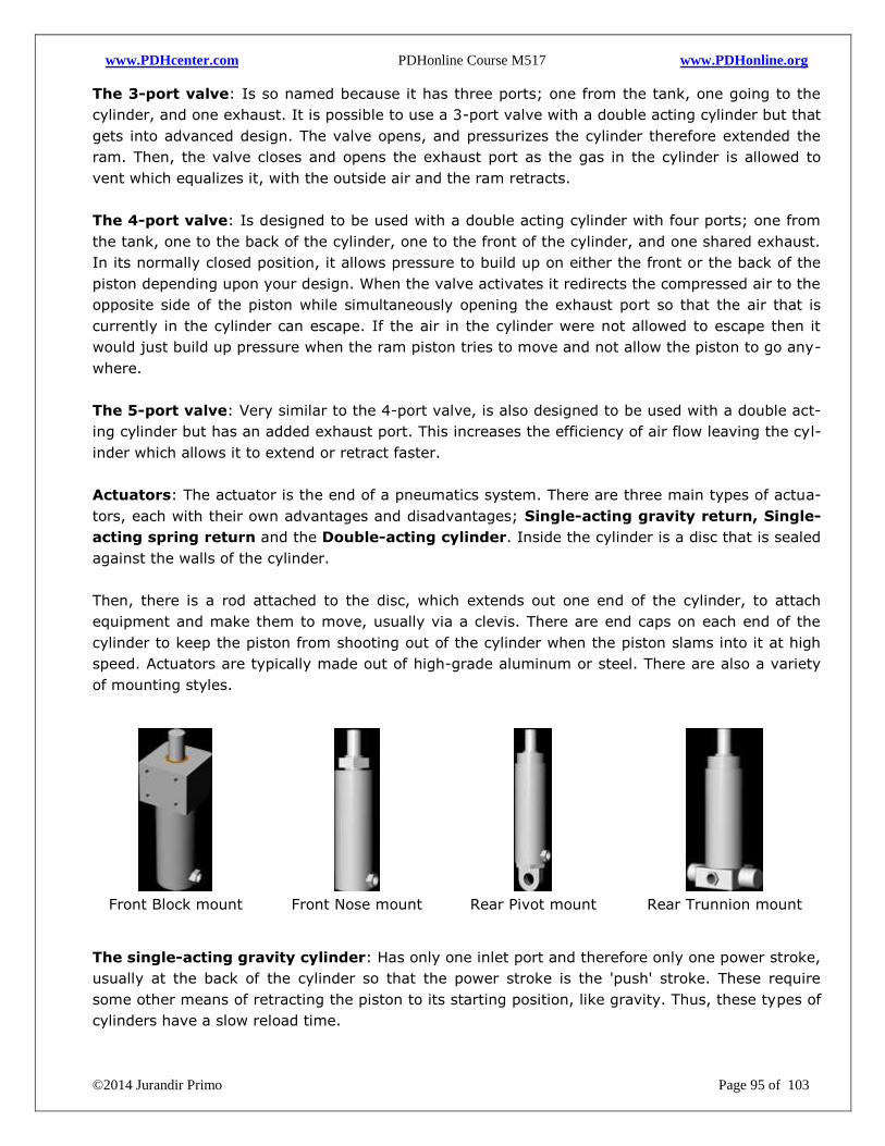
www.PDHcenter.com PDHonline Course M517 www.PDHonline.org
©2014 Jurandir Primo Page 95 of 103
The 3-port valve: Is so named because it has three ports; one from the tank, one going to the
cylinder, and one exhaust. It is possible to use a 3-port valve with a double acting cylinder but that
gets into advanced design. The valve opens, and pressurizes the cylinder therefore extended the
ram. Then, the valve closes and opens the exhaust port as the gas in the cylinder is allowed to
vent which equalizes it, with the outside air and the ram retracts.
The 4-port valve: Is designed to be used with a double acting cylinder with four ports; one from
the tank, one to the back of the cylinder, one to the front of the cylinder, and one shared exhaust.
In its normally closed position, it allows pressure to build up on either the front or the back of the
piston depending upon your design. When the valve activates it redirects the compressed air to the
opposite side of the piston while simultaneously opening the exhaust port so that the air that is
currently in the cylinder can escape. If the air in the cylinder were not allowed to escape then it
would just build up pressure when the ram piston tries to move and not allow the piston to go any-
where.
The 5-port valve: Very similar to the 4-port valve, is also designed to be used with a double act-
ing cylinder but has an added exhaust port. This increases the efficiency of air flow leaving the cyl-
inder which allows it to extend or retract faster.
Actuators: The actuator is the end of a pneumatics system. There are three main types of actua-
tors, each with their own advantages and disadvantages; Single-acting gravity return, Single-
acting spring return and the Double-acting cylinder. Inside the cylinder is a disc that is sealed
against the walls of the cylinder.
Then, there is a rod attached to the disc, which extends out one end of the cylinder, to attach
equipment and make them to move, usually via a clevis. There are end caps on each end of the
cylinder to keep the piston from shooting out of the cylinder when the piston slams into it at high
speed. Actuators are typically made out of high-grade aluminum or steel. There are also a variety
of mounting styles.
Front Block mount
Front Nose mount
Rear Pivot mount
Rear Trunnion mount
The single-acting gravity cylinder: Has only one inlet port and therefore only one power stroke,
usually at the back of the cylinder so that the power stroke is the 'push' stroke. These require
some other means of retracting the piston to its starting position, like gravity. Thus, these types of
cylinders have a slow reload time.
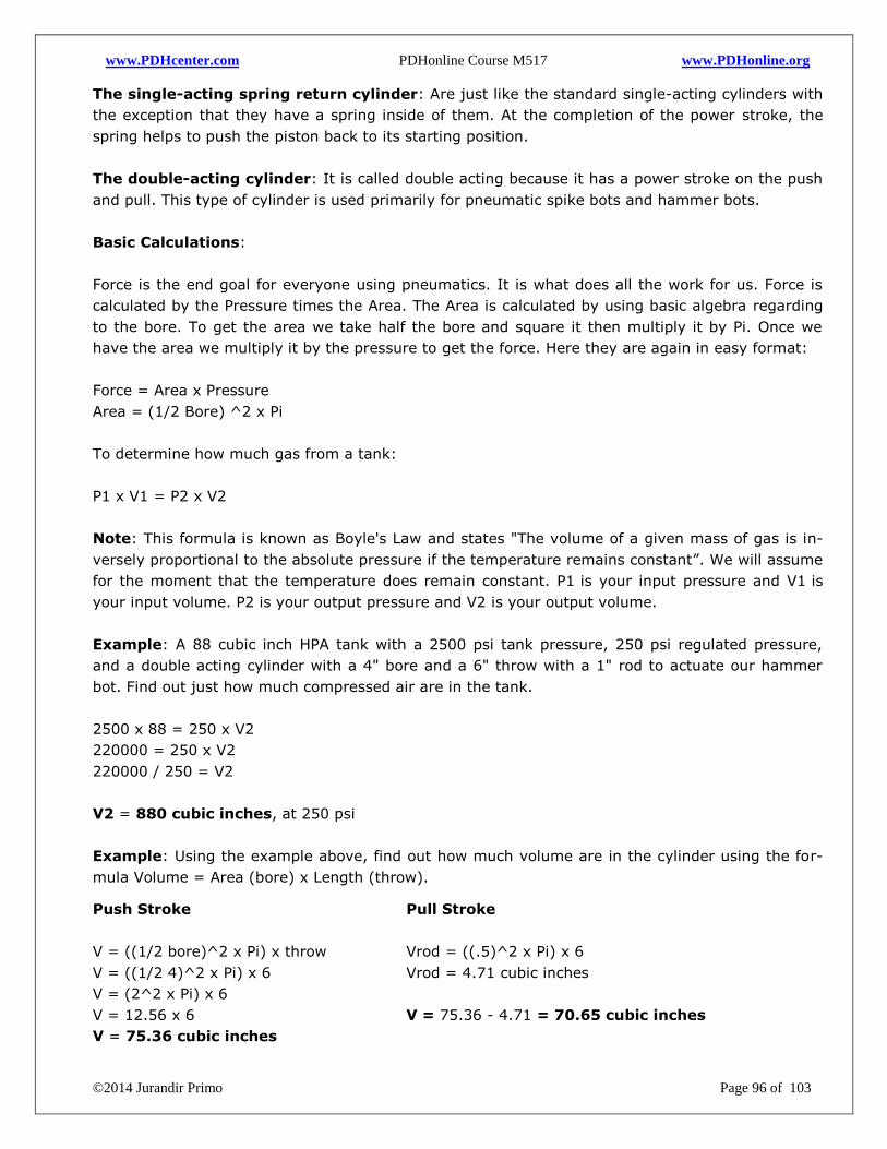
www.PDHcenter.com PDHonline Course M517 www.PDHonline.org
©2014 Jurandir Primo Page 96 of 103
The single-acting spring return cylinder: Are just like the standard single-acting cylinders with
the exception that they have a spring inside of them. At the completion of the power stroke, the
spring helps to push the piston back to its starting position.
The double-acting cylinder: It is called double acting because it has a power stroke on the push
and pull. This type of cylinder is used primarily for pneumatic spike bots and hammer bots.
Basic Calculations:
Force is the end goal for everyone using pneumatics. It is what does all the work for us. Force is
calculated by the Pressure times the Area. The Area is calculated by using basic algebra regarding
to the bore. To get the area we take half the bore and square it then multiply it by Pi. Once we
have the area we multiply it by the pressure to get the force. Here they are again in easy format:
Force = Area x Pressure
Area = (1/2 Bore) ^2 x Pi
To determine how much gas from a tank:
P1 x V1 = P2 x V2
Note: This formula is known as Boyle's Law and states "The volume of a given mass of gas is in-
versely proportional to the absolute pressure if the temperature remains constant”. We will assume
for the moment that the temperature does remain constant. P1 is your input pressure and V1 is
your input volume. P2 is your output pressure and V2 is your output volume.
Example: A 88 cubic inch HPA tank with a 2500 psi tank pressure, 250 psi regulated pressure,
and a double acting cylinder with a 4" bore and a 6" throw with a 1" rod to actuate our hammer
bot. Find out just how much compressed air are in the tank.
2500 x 88 = 250 x V2
220000 = 250 x V2
220000 / 250 = V2
V2 = 880 cubic inches, at 250 psi
Example: Using the example above, find out how much volume are in the cylinder using the for-
mula Volume = Area (bore) x Length (throw).
Push Stroke
V = ((1/2 bore)^2 x Pi) x throw
V = ((1/2 4)^2 x Pi) x 6
V = (2^2 x Pi) x 6
V = 12.56 x 6
V = 75.36 cubic inches
Pull Stroke
Vrod = ((.5)^2 x Pi) x 6
Vrod = 4.71 cubic inches
V = 75.36 - 4.71 = 70.65 cubic inches

www.PDHcenter.com PDHonline Course M517 www.PDHonline.org
©2014 Jurandir Primo Page 97 of 103
Now that we have total volume for the push, stroke (75.36) and the pull stroke (70.65) we can add
them together to get 146.01 cubic inches. Now, we divide that number into the available volume
that the tank has:
Force = Area x Pressure and we know that we have an area equal to 12.56 square inches on the
face of the piston in the 'push' stroke and (12.56 - 0.785) 11.775 square inches on the face of the
piston in the 'pull stroke.
Push Force = 12.56 x 250
Pull Force = 11.775 x 250
The calculated volume is 880 cubic inches / 146.01 (total cylinder volume)= 6.02 total shots and
reloads (12 total actuations) with 3140 pounds of force on the push stroke and 2944 pounds of
force on the return stroke.
The Boyle's Law says, "The volume of a given mass of gas is inversely proportional to the absolute
pressure if the temperature remains constant?" So, what happens if we change the temperature?
Well, there is a new law that comes into play called the General Gas Law that states the relation
between Pressure and Temperature.
P1 / P2 = T1 / T2.
Where:
P1 = Initial Pressure
P2 = Final Pressure
T1 = Initial Temperature (Absolute)
T2 = Final Temperature (Absolute)
Note: Temperature means "Absolute Temperature". Since the temperature at which molecules
stop moving is -460 degrees Fahrenheit, also known as, Absolute Zero, we have to add 460 to
whatever temperature above 0 degrees Fahrenheit that we want to work with. This is known as the
Rankine scale. So, 50 degrees Fahrenheit (50 + 460) = 510 Rankine.
Example: Let us put an electric heat wrap on the tank but not turn it on yet. The heat wrap gets
the tank up to 170 degrees Fahrenheit. So, the absolute temperature at the beginning of the
match is really 545. At 170 degrees Fahrenheit, the absolute temperature is only 630. So, if we
apply the General Gas Law:
2500 (P1) / x (P2) = 545 (T1) / 630 (T2) = 2890 psi.
The Technical Regulations say that a bot can carry no more than 2500 psi of N2 or HPA on board
at any time (8.2.2.a of Tech Reg. 2.2). This is why it is stated in the Technical Regulations section
8.9.5 - Pneumatic heaters not allowed. Then, determine how many units of atmosphere are availa-
ble in the tank by multiplying the pressure by the volume:
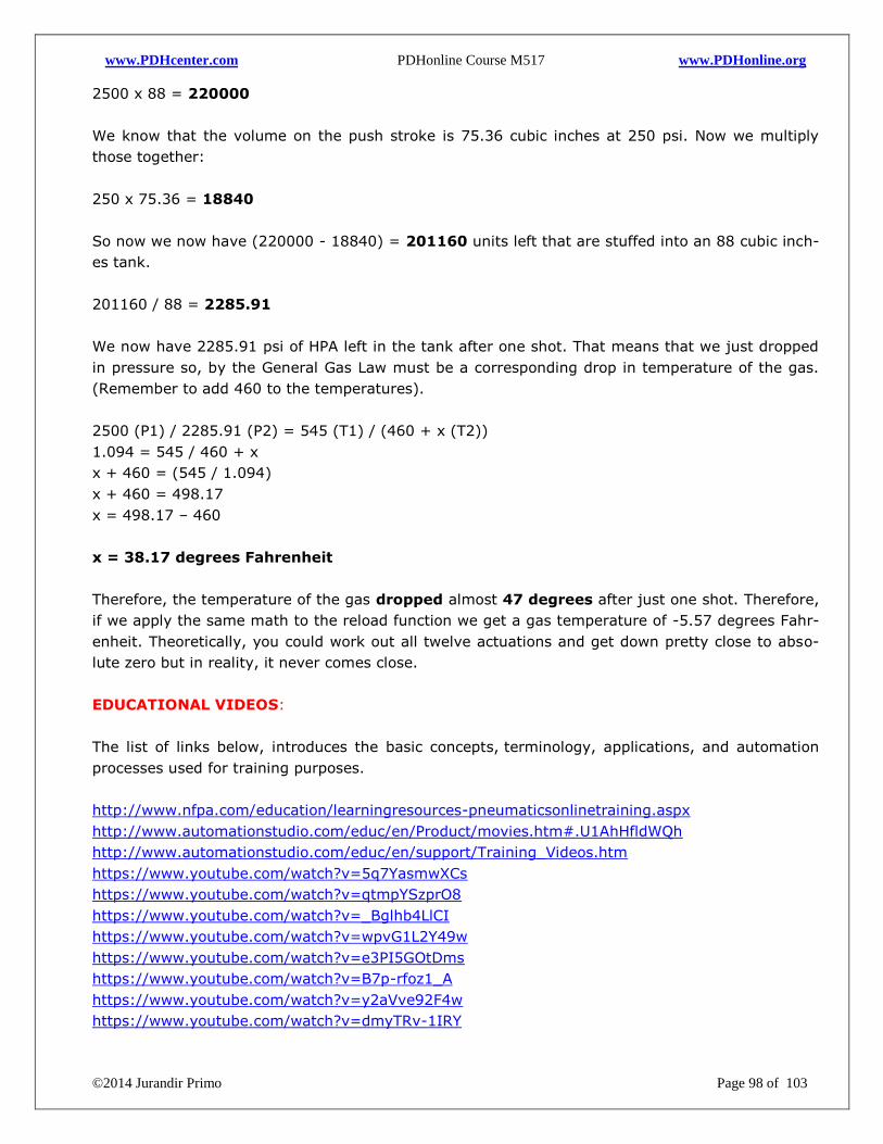
www.PDHcenter.com PDHonline Course M517 www.PDHonline.org
©2014 Jurandir Primo Page 98 of 103
2500 x 88 = 220000
We know that the volume on the push stroke is 75.36 cubic inches at 250 psi. Now we multiply
those together:
250 x 75.36 = 18840
So now we now have (220000 - 18840) = 201160 units left that are stuffed into an 88 cubic inch-
es tank.
201160 / 88 = 2285.91
We now have 2285.91 psi of HPA left in the tank after one shot. That means that we just dropped
in pressure so, by the General Gas Law must be a corresponding drop in temperature of the gas.
(Remember to add 460 to the temperatures).
2500 (P1) / 2285.91 (P2) = 545 (T1) / (460 + x (T2))
1.094 = 545 / 460 + x
x + 460 = (545 / 1.094)
x + 460 = 498.17
x = 498.17 – 460
x = 38.17 degrees Fahrenheit
Therefore, the temperature of the gas dropped almost 47 degrees after just one shot. Therefore,
if we apply the same math to the reload function we get a gas temperature of -5.57 degrees Fahr-
enheit. Theoretically, you could work out all twelve actuations and get down pretty close to abso-
lute zero but in reality, it never comes close.
EDUCATIONAL VIDEOS:
The list of links below, introduces the basic concepts, terminology, applications, and automation
processes used for training purposes.
http://www.nfpa.com/education/learningresources-pneumaticsonlinetraining.aspx
http://www.automationstudio.com/educ/en/Product/movies.htm#.U1AhHfldWQh
http://www.automationstudio.com/educ/en/support/Training_Videos.htm
https://www.youtube.com/watch?v=5q7YasmwXCs
https://www.youtube.com/watch?v=qtmpYSzprO8
https://www.youtube.com/watch?v=_Bglhb4LlCI
https://www.youtube.com/watch?v=wpvG1L2Y49w
https://www.youtube.com/watch?v=e3PI5GOtDms
https://www.youtube.com/watch?v=B7p-rfoz1_A
https://www.youtube.com/watch?v=y2aVve92F4w
https://www.youtube.com/watch?v=dmyTRv-1IRY
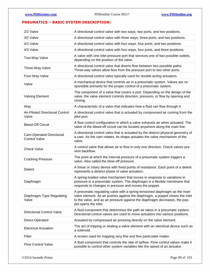
www.PDHcenter.com PDHonline Course M517 www.PDHonline.org
©2014 Jurandir Primo Page 99 of 103
PNEUMATICS – BASIC SYSTEM DESCRIPTION:
2/2 Valve A directional control valve with two ways, two ports, and two positions.
3/2 Valve A directional control valve with three ways, three ports, and two positions.
4/2 Valve A directional control valve with four ways, four ports, and two positions.
4/3 Valve A directional control valve with four ways, four ports, and three positions.
Two-Way Valve A valve with one inlet pressure port that services one of two possible outlets,
depending on the position of the valve.
Three-Way Valve A directional control valve that diverts flow between two possible paths.
Three-way valves allow flow from the pressure port to two other ports.
Four-Way Valve A directional control valve typically used for double-acting actuators.
Valve A mechanical device that controls air in a pneumatic system. Valves are re-
sponsible primarily for the proper control of a pneumatic system.
Valving Element
The component of a valve that covers a port. Depending on the design of the
valve, the valve element controls direction, pressure, or flow by opening and
closing.
Way A characteristic of a valve that indicates how a fluid can flow through it.
Air-Piloted Directional Control
Valve
A directional control valve that is actuated by compressed air coming from the
pilot port.
Bleed-Off Circuit
A flow control configuration in which a valve exhausts air when actuated. The
valve of the bleed-off circuit can be located anywhere along the main line.
Cam-Operated Directional
Control Valve
A directional control valve that is actuated by the distinct physical geometry of
a cam. As the cam rotates, its shape actuates the valve mechanism of the
valve.
Check Valve
A control valve that allows air to flow in only one direction. Check valves pre-
vent backflow.
Cracking Pressure
The point at which the internal pressure of a pneumatic system triggers a
valve. Also called the blow-off pressure.
Detent
A linear or rotary device with fixed points of resistance. Each point of a detent
represents a distinct phase of valve actuation.
Diaphragm
A spring-loaded valve mechanism that moves in response to variations in
pressure in a pneumatic system. The diaphragm is a flexible membrane that
responds to changes in pressure and moves the poppet.
Diaphragm-Type Regulating
Valve
A pneumatic regulating valve with a spring-tensioned diaphragm as the main
valve element. As air pushes against the diaphragm, a poppet closes the inlet
to the valve, and as air pressure against the diaphragm decreases, the pop-
pet opens the inlet.
Directional Control Valve
A fluid component that determines the path air takes in a pneumatic system.
Directional control valves are used to move actuators into various positions.
Direct-Operated Actuated by compressed air pressing directly on the valve element.
Electrical Actuation
The act of tripping or seating a valve element with an electrical device such as
a solenoid.
Filter A screen used for trapping very fine and fine particulate matter.
Flow Control Valve
A fluid component that controls the rate of airflow. Flow control valves make it
possible to control other system variables like the speed of an actuator.
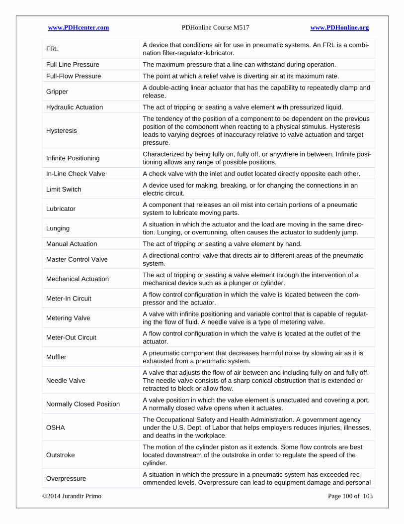
www.PDHcenter.com PDHonline Course M517 www.PDHonline.org
©2014 Jurandir Primo Page 100 of 103
FRL
A device that conditions air for use in pneumatic systems. An FRL is a combi-
nation filter-regulator-lubricator.
Full Line Pressure The maximum pressure that a line can withstand during operation.
Full-Flow Pressure The point at which a relief valve is diverting air at its maximum rate.
Gripper
A double-acting linear actuator that has the capability to repeatedly clamp and
release.
Hydraulic Actuation The act of tripping or seating a valve element with pressurized liquid.
Hysteresis
The tendency of the position of a component to be dependent on the previous
position of the component when reacting to a physical stimulus. Hysteresis
leads to varying degrees of inaccuracy relative to valve actuation and target
pressure.
Infinite Positioning
Characterized by being fully on, fully off, or anywhere in between. Infinite posi-
tioning allows any range of possible positions.
In-Line Check Valve A check valve with the inlet and outlet located directly opposite each other.
Limit Switch
A device used for making, breaking, or for changing the connections in an
electric circuit.
Lubricator
A component that releases an oil mist into certain portions of a pneumatic
system to lubricate moving parts.
Lunging
A situation in which the actuator and the load are moving in the same direc-
tion. Lunging, or overrunning, often causes the actuator to suddenly jump.
Manual Actuation The act of tripping or seating a valve element by hand.
Master Control Valve
A directional control valve that directs air to different areas of the pneumatic
system.
Mechanical Actuation
The act of tripping or seating a valve element through the intervention of a
mechanical device such as a plunger or cylinder.
Meter-In Circuit
A flow control configuration in which the valve is located between the com-
pressor and the actuator.
Metering Valve
A valve with infinite positioning and variable control that is capable of regulat-
ing the flow of fluid. A needle valve is a type of metering valve.
Meter-Out Circuit
A flow control configuration in which the valve is located at the outlet of the
actuator.
Muffler
A pneumatic component that decreases harmful noise by slowing air as it is
exhausted from a pneumatic system.
Needle Valve
A valve that adjusts the flow of air between and including fully on and fully off.
The needle valve consists of a sharp conical obstruction that is extended or
retracted to block or allow flow.
Normally Closed Position
A valve position in which the valve element is unactuated and covering a port.
A normally closed valve opens when it actuates.
OSHA
The Occupational Safety and Health Administration. A government agency
under the U.S. Dept. of Labor that helps employers reduces injuries, illnesses,
and deaths in the workplace.
Outstroke
The motion of the cylinder piston as it extends. Some flow controls are best
located downstream of the outstroke in order to regulate the speed of the
cylinder.
Overpressure
A situation in which the pressure in a pneumatic system has exceeded rec-
ommended levels. Overpressure can lead to equipment damage and personal
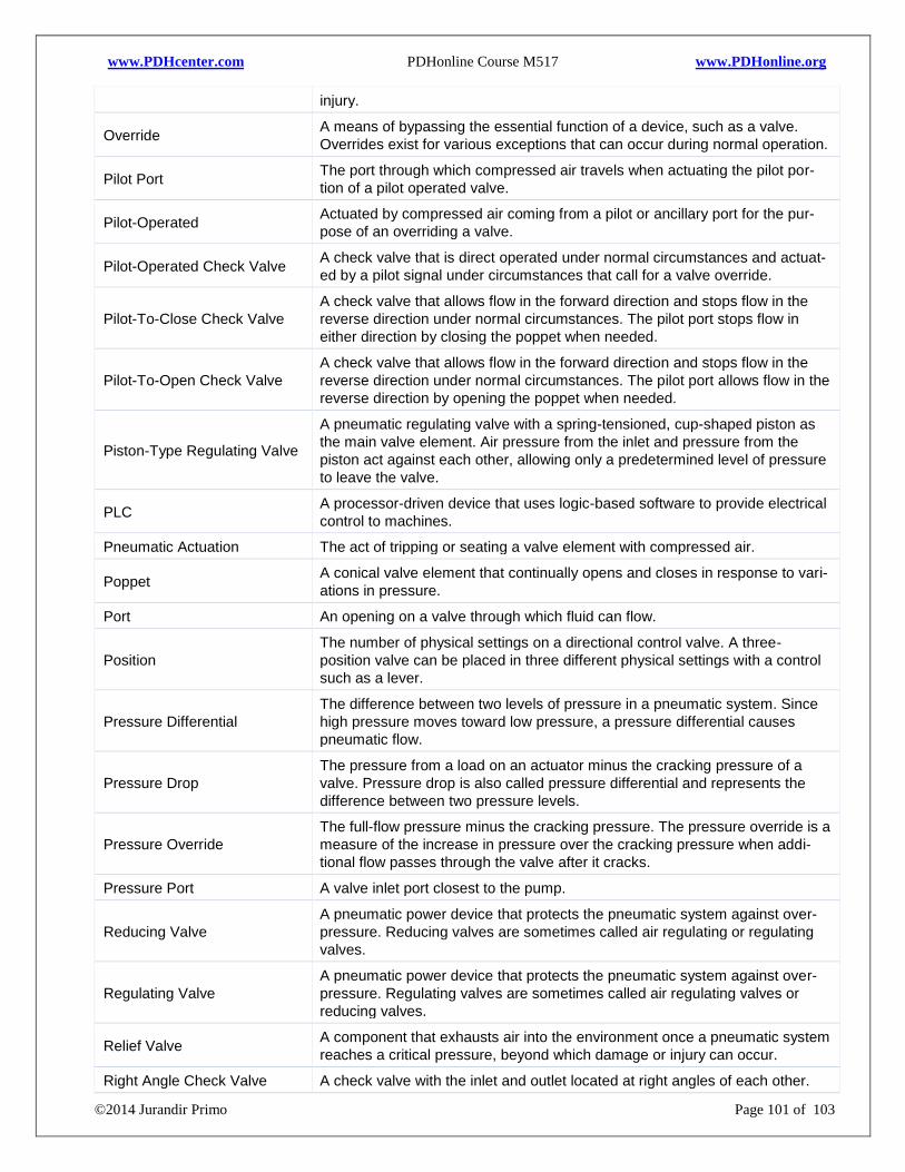
www.PDHcenter.com PDHonline Course M517 www.PDHonline.org
©2014 Jurandir Primo Page 101 of 103
injury.
Override
A means of bypassing the essential function of a device, such as a valve.
Overrides exist for various exceptions that can occur during normal operation.
Pilot Port
The port through which compressed air travels when actuating the pilot por-
tion of a pilot operated valve.
Pilot-Operated
Actuated by compressed air coming from a pilot or ancillary port for the pur-
pose of an overriding a valve.
Pilot-Operated Check Valve
A check valve that is direct operated under normal circumstances and actuat-
ed by a pilot signal under circumstances that call for a valve override.
Pilot-To-Close Check Valve
A check valve that allows flow in the forward direction and stops flow in the
reverse direction under normal circumstances. The pilot port stops flow in
either direction by closing the poppet when needed.
Pilot-To-Open Check Valve
A check valve that allows flow in the forward direction and stops flow in the
reverse direction under normal circumstances. The pilot port allows flow in the
reverse direction by opening the poppet when needed.
Piston-Type Regulating Valve
A pneumatic regulating valve with a spring-tensioned, cup-shaped piston as
the main valve element. Air pressure from the inlet and pressure from the
piston act against each other, allowing only a predetermined level of pressure
to leave the valve.
PLC
A processor-driven device that uses logic-based software to provide electrical
control to machines.
Pneumatic Actuation The act of tripping or seating a valve element with compressed air.
Poppet
A conical valve element that continually opens and closes in response to vari-
ations in pressure.
Port An opening on a valve through which fluid can flow.
Position
The number of physical settings on a directional control valve. A three-
position valve can be placed in three different physical settings with a control
such as a lever.
Pressure Differential
The difference between two levels of pressure in a pneumatic system. Since
high pressure moves toward low pressure, a pressure differential causes
pneumatic flow.
Pressure Drop
The pressure from a load on an actuator minus the cracking pressure of a
valve. Pressure drop is also called pressure differential and represents the
difference between two pressure levels.
Pressure Override
The full-flow pressure minus the cracking pressure. The pressure override is a
measure of the increase in pressure over the cracking pressure when addi-
tional flow passes through the valve after it cracks.
Pressure Port A valve inlet port closest to the pump.
Reducing Valve
A pneumatic power device that protects the pneumatic system against over-
pressure. Reducing valves are sometimes called air regulating or regulating
valves.
Regulating Valve
A pneumatic power device that protects the pneumatic system against over-
pressure. Regulating valves are sometimes called air regulating valves or
reducing valves.
Relief Valve
A component that exhausts air into the environment once a pneumatic system
reaches a critical pressure, beyond which damage or injury can occur.
Right Angle Check Valve A check valve with the inlet and outlet located at right angles of each other.
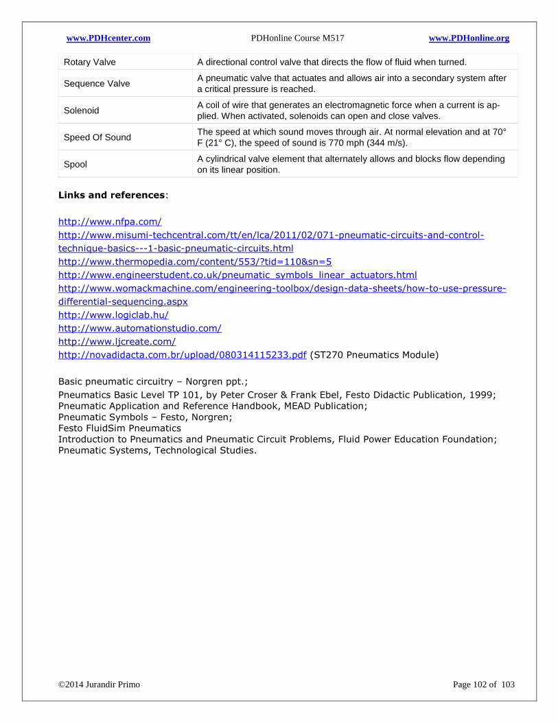
www.PDHcenter.com PDHonline Course M517 www.PDHonline.org
©2014 Jurandir Primo Page 102 of 103
Rotary Valve A directional control valve that directs the flow of fluid when turned.
Sequence Valve
A pneumatic valve that actuates and allows air into a secondary system after
a critical pressure is reached.
Solenoid
A coil of wire that generates an electromagnetic force when a current is ap-
plied. When activated, solenoids can open and close valves.
Speed Of Sound
The speed at which sound moves through air. At normal elevation and at 70°
F (21° C), the speed of sound is 770 mph (344 m/s).
Spool
A cylindrical valve element that alternately allows and blocks flow depending
on its linear position.
Links and references:
http://www.nfpa.com/
http://www.misumi-techcentral.com/tt/en/lca/2011/02/071-pneumatic-circuits-and-control-
technique-basics---1-basic-pneumatic-circuits.html
http://www.thermopedia.com/content/553/?tid=110&sn=5
http://www.engineerstudent.co.uk/pneumatic_symbols_linear_actuators.html
http://www.womackmachine.com/engineering-toolbox/design-data-sheets/how-to-use-pressure-
differential-sequencing.aspx
http://www.logiclab.hu/
http://www.automationstudio.com/
http://www.ljcreate.com/
http://novadidacta.com.br/upload/080314115233.pdf (ST270 Pneumatics Module)
Basic pneumatic circuitry – Norgren ppt.;
Pneumatics Basic Level TP 101, by Peter Croser & Frank Ebel, Festo Didactic Publication, 1999;
Pneumatic Application and Reference Handbook, MEAD Publication;
Pneumatic Symbols – Festo, Norgren;
Festo FluidSim Pneumatics
Introduction to Pneumatics and Pneumatic Circuit Problems, Fluid Power Education Foundation;
Pneumatic Systems, Technological Studies.