Embed Size (px)
Citation preview
Pneumatics
Some basics for FIRST Robotics
ROBOTICS ACADEMY: FRC PNEUMATICS
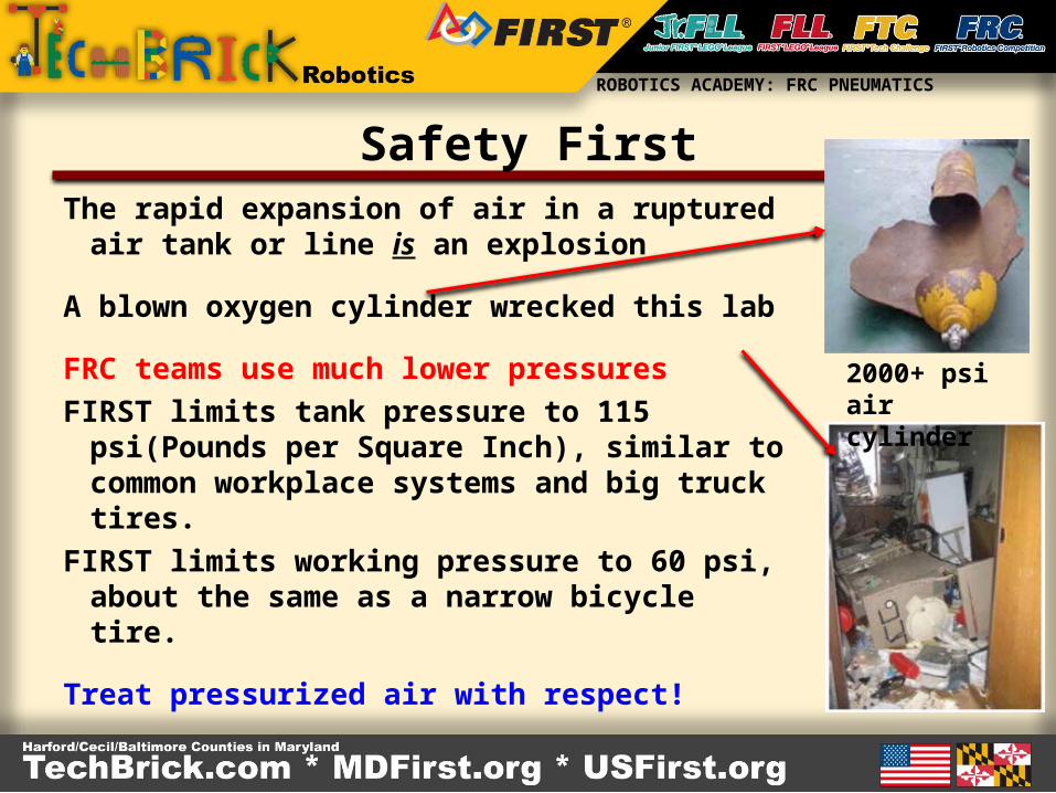
Safety FirstThe rapid expansion of air in a ruptured air
tank or line is an explosion
A blown oxygen cylinder wrecked this lab
FRC teams use much lower pressures
FIRST limits tank pressure to 115 psi(Pounds per Square Inch), similar to common workplace systems and big truck tires.
FIRST limits working pressure to 60 psi, about the same as a narrow bicycle tire.
Treat pressurized air with respect!
2000+ psi aircylinder
ROBOTICS ACADEMY: FRC PNEUMATICS
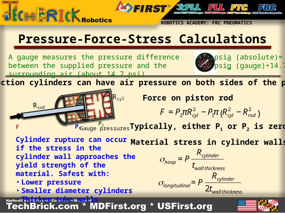
Pressure-Force-Stress Calculations
P2P1F
Rcyl
Rrod
Dual action cylinders can have air pressure on both sides of the piston
€
F = P2πRcyl2 − P1π Rcyl
2 − Rrod2
( )
Force on piston rod
Material stress in cylinder walls
€
σhoop = PRcylindertwall thickness
€
σlongitudinal = PRcylinder
2twall thickness
Cylinder rupture can occur if the stress in the cylinder wall approaches the yield strength of the material. Safest with:• Lower pressure• Smaller diameter cylinders• Thicker tube walls
Typically, either P1 or P2 is zero
A gauge measures the pressure difference between the supplied pressure and the surrounding air (about 14.7 psi)
psia (absolute)=psig (gauge)+14.7
Gauge pressures
ROBOTICS ACADEMY: FRC PNEUMATICS
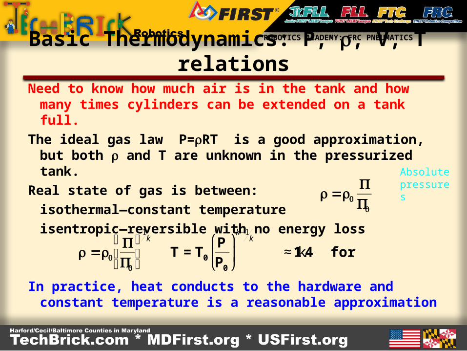
Basic Thermodynamics: P, r, V, T relationsNeed to know how much air is in the tank and how
many times cylinders can be extended on a tank full.
The ideal gas law P=rRT is a good approximation, but both r and T are unknown in the pressurized tank.
Real state of gas is between:
isothermal—constant temperature
isentropic—reversible with no energy loss
In practice, heat conducts to the hardware and constant temperature is a reasonable approximation
€
ρ =ρ0
PP0
€
ρ =ρ0
PP0
⎛
⎝ ⎜
⎞
⎠ ⎟
1k
Τ = Τ0
P
P0
⎛
⎝ ⎜
⎞
⎠ ⎟
k−1k
k ≈ 1.4 for air
Absolute pressures
ROBOTICS ACADEMY: FRC PNEUMATICS
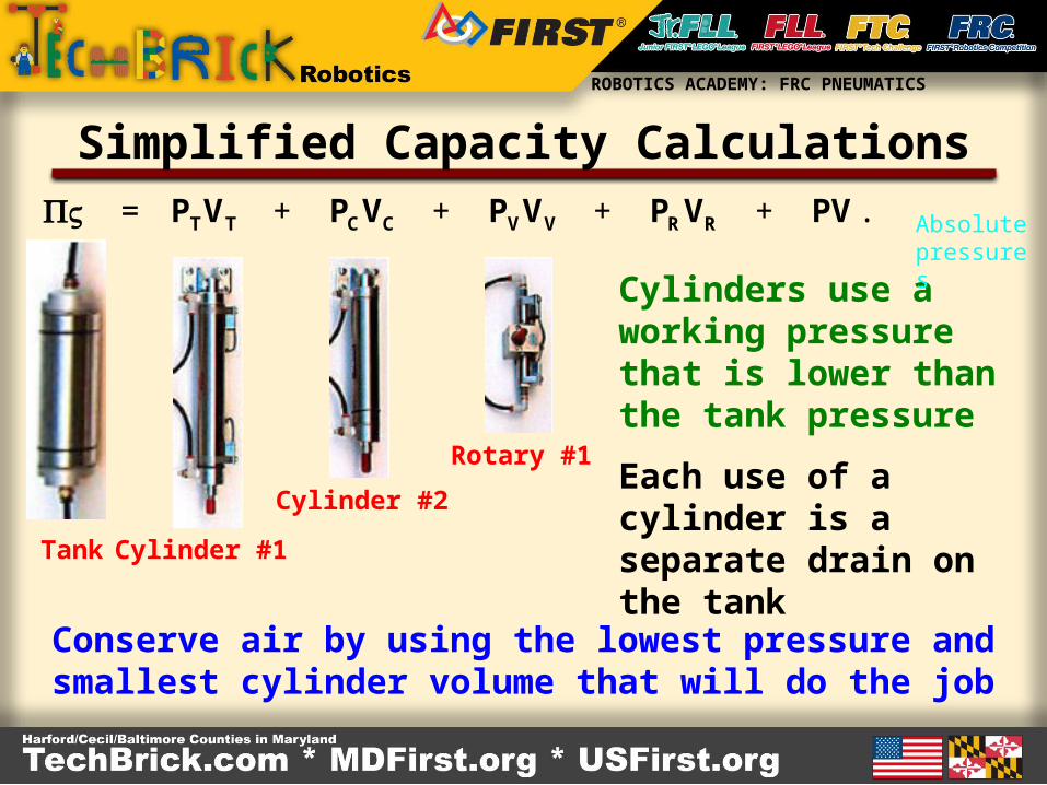
Simplified Capacity Calculations
€
PV = PTVT + PCVC + PVVV + PRVR + PV...
Tank Cylinder #1
Cylinder #2
Rotary #1Each use of a cylinder is a separate drain on the tank
Conserve air by using the lowest pressure and smallest cylinder volume that will do the job
Cylinders use a working pressure that is lower than the tank pressure
Absolute pressures
ROBOTICS ACADEMY: FRC PNEUMATICS
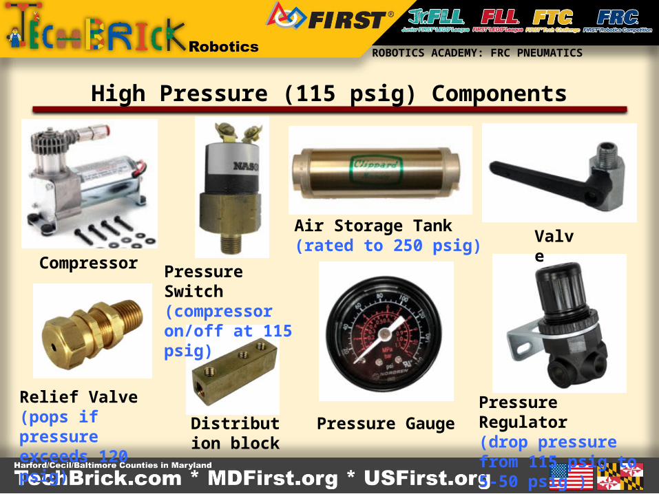
High Pressure (115 psig) Components
Compressor
Distribution block
Pressure Switch (compressor on/off at 115 psig)
Relief Valve(pops if pressure exceeds 120 psig)
Air Storage Tank(rated to 250 psig)
Pressure Gauge
Valve
Pressure Regulator(drop pressure from 115 psig to 5-50 psig )
ROBOTICS ACADEMY: FRC PNEUMATICS
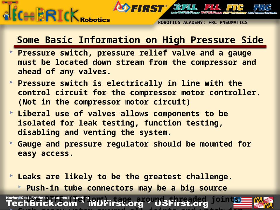
Some Basic Information on High Pressure Side Pressure switch, pressure relief valve and a gauge must be located
down stream from the compressor and ahead of any valves. Pressure switch is electrically in line with the control circuit for the
compressor motor controller. (Not in the compressor motor circuit) Liberal use of valves allows components to be isolated for leak
testing, function testing, disabling and venting the system. Gauge and pressure regulator should be mounted for easy access.
Leaks are likely to be the greatest challenge. Push-in tube connectors may be a big source Use PTFE (Teflon®) tape around threaded joints
Swab soapy water around all joints and watch for bubbles
ROBOTICS ACADEMY: FRC PNEUMATICS
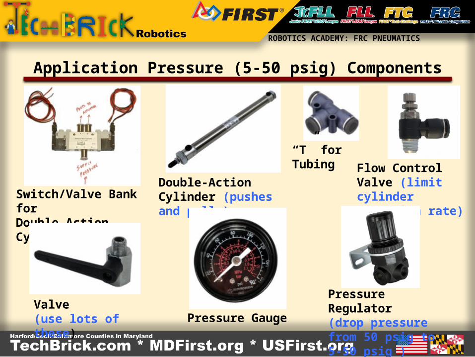
Application Pressure (5-50 psig) Components
Switch/Valve Bank for Double-Action Cylinder
Double-Action Cylinder (pushes and pulls)
“T” for Tubing
Flow Control Valve (limit cylinder extension rate)
Valve (use lots of these) Pressure Gauge
Pressure Regulator(drop pressure from 50 psig to 5-50 psig )
ROBOTICS ACADEMY: FRC PNEUMATICS
Tips for the Low Pressure Components Use the lowest possible working pressure to minimize air
usage, abuse of hardware and potential for injury. Multiple regulators allows several working pressures. Use a gauge after every regulator to set pressure on that leg Use flow control valves to limit the extension/retraction rate.
Also, safer due to reduced velocity of components.
Again, leaks may be the biggest challenge.
ROBOTICS ACADEMY: FRC PNEUMATICS
Questions?
???