Embed Size (px)
Citation preview
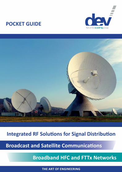
THE ART OF ENGINEERING
POCKET GUIDE
Integrated RF Solutions for Signal Distribution
Broadcast and Satellite Communications
Broadband HFC and FTTx Networks
THE ART OF ENGINEERINGTHE ART OF ENGINEERING2
List of Abbreviations
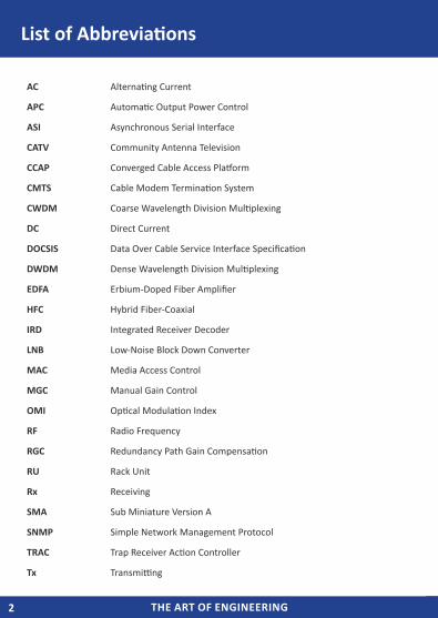
AC Alternating Current
APC Automatic Output Power Control
ASI Asynchronous Serial Interface
CATV Community Antenna Television
CCAP Converged Cable Access Platform
CMTS Cable Modem Termination System
CWDM Coarse Wavelength Division Multiplexing
DC Direct Current
DOCSIS Data Over Cable Service Interface Specification
DWDM Dense Wavelength Division Multiplexing
EDFA Erbium-Doped Fiber Amplifier
HFC Hybrid Fiber-Coaxial
IRD Integrated Receiver Decoder
LNB Low-Noise Block Down Converter
MAC Media Access Control
MGC Manual Gain Control
OMI Optical Modulation Index
RF Radio Frequency
RGC Redundancy Path Gain Compensation
RU Rack Unit
Rx Receiving
SMA Sub Miniature Version A
SNMP Simple Network Management Protocol
TRAC Trap Receiver Action Controller
Tx Transmitting
THE ART OF ENGINEERING 3THE ART OF ENGINEERING
Cabl
e, H
FC, F
TTx
Broa
dcas
t and
Sat
ellit
e Co
mm
unic
ation
s
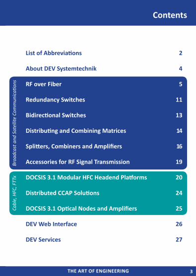
List of Abbreviations 2
About DEV Systemtechnik 4
RF over Fiber 5
Redundancy Switches 11
Bidirectional Switches 13
Distributing and Combining Matrices 14
Splitters, Combiners and Amplifiers 16
Accessories for RF Signal Transmission 19
DOCSIS 3.1 Modular HFC Headend Platforms 20
Distributed CCAP Solutions 24
DOCSIS 3.1 Optical Nodes and Amplifiers 25
DEV Web Interface 26
DEV Services 27
Contents
THE ART OF ENGINEERINGTHE ART OF ENGINEERING4
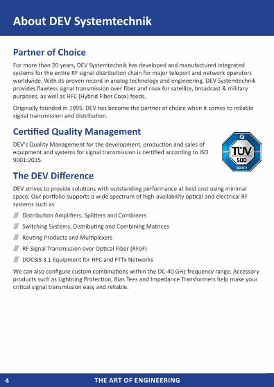
Partner of ChoiceFor more than 20 years, DEV Systemtechnik has developed and manufactured integrated systems for the entire RF signal distribution chain for major teleport and network operators worldwide. With its proven record in analog technology and engineering, DEV Systemtechnik provides flawless signal transmission over fiber and coax for satellite, broadcast & military purposes, as well as HFC (Hybrid Fiber Coax) feeds.
Originally founded in 1995, DEV has become the partner of choice when it comes to reliable signal transmission and distribution.
Certified Quality ManagementDEV’s Quality Management for the development, production and sales of equipment and systems for signal transmission is certified according to ISO 9001:2015.
The DEV DifferenceDEV strives to provide solutions with outstanding performance at best cost using minimal space. Our portfolio supports a wide spectrum of high-availability optical and electrical RF systems such as:
Distribution Amplifiers, Splitters and Combiners
Switching Systems, Distributing and Combining Matrices
Routing Products and Multiplexers
RF Signal Transmission over Optical Fiber (RFoF)
DOCSIS 3.1 Equipment for HFC and FTTx Networks
We can also configure custom combinations within the DC-40 GHz frequency range. Accessory products such as Lightning Protection, Bias Tees and Impedance Transformers help make your critical signal transmission easy and reliable.
About DEV Systemtechnik
THE ART OF ENGINEERING 5THE ART OF ENGINEERING
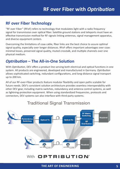
RF over Fiber Technology“RF over Fiber” (RFoF) refers to technology that modulates light with a radio frequency signal for transmission over optical fiber. Satellite ground stations and teleports must have an effective transmission method for RF signals linking antennas, signal management apparatus, and diverse equipment centers.
Overcoming the limitations of coax cable, fiber links are the best choice to assure optimal signal quality, especially over longer distances. RFoF offers important advantages over coax: minimal losses, preserved signal quality, muted crosstalk, and multiple channels over one physical medium.
Optribution – The All-in-One SolutionWith Optribution, DEV offers a product line serving both electrical and optical functions in one system. All products are engineered, developed and manufactured in Germany. Optribution allows sophisticated switching, redundant configurations, and long-distance signal transport up to 200 km.
All of our RF-over-Fiber products feature modular flexibility and open paths scalable for future needs. DEV’s consistent solution architecture provides seamless interoperability with other DEV gear, including matrix switches, redundancy and antenna control systems, as well as lightning-protection equipment. When using standardized frequencies, protocols and connectors, DEV systems can also interface with third-party systems.
RF over Fiber with Optribution
THE ART OF ENGINEERINGTHE ART OF ENGINEERING6
RF over Fiber - Optribution
RF over Fiber Indoor Chassis
DEV 4111
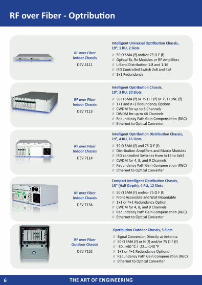
Intelligent Universal Optribution Chassis, 19“, 1 RU, 2 Slots
50 Ω SMA (f) and/or 75 Ω F (f) Optical Tx, Rx Modules or RF Amplifiers L-Band Distribution 1:8 and 1:16 IRD Controlled Switch 2x8 and 4x8 1+1 Redundancy
RF over Fiber Indoor Chassis
DEV 7113
Intelligent Optribution Chassis, 19“, 3 RU, 20 Slots
50 Ω SMA (f) or 75 Ω F (f) or 75 Ω BNC (f) 1+1 and n+1 Redundancy Options CWDM for up to 8 Channels DWDM for up to 48 Channels Redundancy Path Gain Compensation (RGC) Ethernet to Optical Converter
RF over Fiber Indoor Chassis
DEV 7114
Intelligent Optribution Distribution Chassis, 19”, 4 RU, 16 Slots
50 Ω SMA (f) and 75 Ω F (f) Distribution Amplifiers and Matrix Modules IRD controlled Switches from 4x16 to 4x64 CWDM for 4, 8, and 9 Channels Redundancy Path Gain Compensation (RGC) Ethernet to Optical Converter
RF over Fiber Indoor Chassis
DEV 7134
Compact Intelligent Optribution Chassis, 19“ (Half Depth), 4 RU, 12 Slots
50 Ω SMA (f) and/or 75 Ω F (f) Front Accessible and Wall Mountable 1+1 or 4+1 Redundancy Option CWDM for 4, 8, and 9 Channels Redundancy Path Gain Compensation (RGC) Ethernet to Optical Converter
RF over Fiber Outdoor Chassis
DEV 7152
Optribution Outdoor Chassis, 5 Slots
Signal Conversion Directly at Antenna 50 Ω SMA (f) or N (f) and/or 75 Ω F (f) -30…+60 °C / -22…+140 °F 1+1 or 4+1 Redundancy Options Redundancy Path Gain Compensation (RGC) Ethernet to Optical Converter
THE ART OF ENGINEERING 7THE ART OF ENGINEERING
RF over Fiber - Optribution
Optical L-Band Links
DEV 7232, DEV 7233DEV 7241, DEV 7251DEV 7332, DEV 7333
DEV 7341
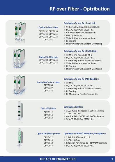
Optribution Tx and Rx L-Band Link
950...2150 MHz and 700...2300 MHz SC/APC, FC/APC or E2000 HRL CWDM and DWDM Applications OMI Optimization Variable Gain and Variable Slope RF Sensing LNB Powering with Current Monitoring
Optical 10 MHz LinkDEV 7238, DEV 7244DEV 7335, DEV 7344
Optribution Tx and Rx 10 MHz Link
10 MHz and 700...2300 MHz SC/APC, FC/APC or E2000 HRL 9 Wavelengths for CWDM Applications Variable Gain and Variable Slope RF Sensing LNB Powering with Current Monitoring
Optical CATV-Band Links DEV 7238DEV 7337DEV 7338
Optribution Tx and Rx CATV-Band Link
10 MHz SC/APC, FC/APC or E2000 HRL 9 Wavelengths for CWDM Applications RF Sensing RF Monitoring Port for Transmitter
Optical Splitters
DEV 7512DEV 7514DEV 7518
Optribution Splitters
1:2, 1:4, 1:8 Bidirectional Optical Splitters 1260...1610 nm Applicable in CWDM and DWDM Systems SC/APC, FC/APC or E2000 HRL
Optical De-/Multiplexers
DEV 7612DEV 7614DEV 7618DEV 7658
Optribution CWDM/DWDM De-/Multiplexers
2:1/1:2, 4:1/1:4 or 8:1/1:8 1470…1610 nm Extension Port for up to 48 DWDM Channels SC/APC, FC/APC or E2000 HRL
THE ART OF ENGINEERINGTHE ART OF ENGINEERING8
RF over Fiber - Optribution
EDFA Modules
DEV 7415DEV 7425
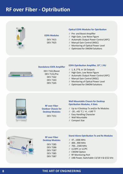
Optical EDFA Modules for Optribution
Pre- and Boost-Amplifier High Gain, Low Noise Figure Automatic Output Power Control (APC) Manual Gain Control (MGC) Monitoring of Optical Power Level Optimized for DWDM Solutions
Standalone EDFA Amplifier
DEV 7161/BoostDEV 7131/Pre
DEV 7162DEV 7163DEV 7165
EDFA Optribution Amplifier, 19“, 1 RU
1, 8, 2*8, or 16 Outputs High Gain, Low Noise Figure Automatic Output Power Control (APC) Manual Gain Control (MGC) Monitoring of Optical Power Level Optimized for DWDM Solutions
RF over Fiber Outdoor Chassis for Desktop Modules
DEV 7151
Wall Mountable Chassis for Desktop Optribution Modules, 4 Slots
Up to 4 Desktop Tx and/or Rx Modules -20…+65 °C / -4…+149 °F Easy Handling Character Wall Mountable Compact Size
RF over Fiber Desktop Modules
DEV 7285 DEV 7286DEV 7287DEV 7385DEV 7387
Stand-Alone Optribution Tx and Rx Modules
47…1006 MHz 400...900 MHz 700...2300 MHz LC/APC or LC/PC CWDM Option RF Monitoring Port LNB Power, Switchable 13/18 V & 0/22 kHz
THE ART OF ENGINEERING 9THE ART OF ENGINEERING
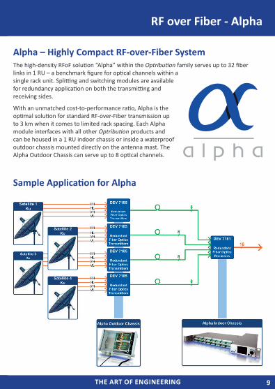
Alpha – Highly Compact RF-over-Fiber SystemThe high-density RFoF solution “Alpha” within the Optribution family serves up to 32 fiber links in 1 RU – a benchmark figure for optical channels within a single rack unit. Splitting and switching modules are available for redundancy application on both the transmitting and receiving sides.
With an unmatched cost-to-performance ratio, Alpha is the optimal solution for standard RF-over-Fiber transmission up to 3 km when it comes to limited rack spacing. Each Alpha module interfaces with all other Optribution products and can be housed in a 1 RU indoor chassis or inside a waterproof outdoor chassis mounted directly on the antenna mast. The Alpha Outdoor Chassis can serve up to 8 optical channels.
Sample Application for Alpha
RF over Fiber - Alpha
THE ART OF ENGINEERINGTHE ART OF ENGINEERING10
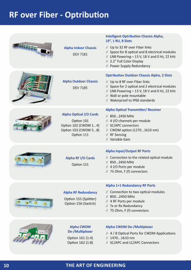
Alpha Indoor Chassis
DEV 7181
Intelligent Optribution Chassis Alpha, 19”, 1 RU, 8 Slots
Up to 32 RF over Fiber links Space for 8 optical and 8 electrical modules LNB Powering – 13 V, 18 V and 0 Hz, 22 kHz 2.2” Full Color Display Power Supply Redundancy
Alpha Outdoor Chassis
DEV 7185
Optribution Outdoor Chassis Alpha, 2 Slots
Up to 8 RF over Fiber links Space for 2 optical and 2 electrical modules LNB Powering – 13 V, 18 V and 0 Hz, 22 kHz Wall or pole mountable Waterproof to IP66 standards
Alpha Optical I/O Cards
Option 101Option 102 (CWDM 1...4)Option 103 (CWDM 5...8)
Option 111
Alpha Optical Transmitter/ Receiver
850...2450 MHz 4 I/O channels per module SC/APC connectors CWDM option (1270...1610 nm) RF Sensing Variable Gain
Alpha RF I/O Cards
Option 151
Alpha Input/Output RF Ports
Connection to the related optical module 850...2450 MHz 4 I/O Ports per module 75 Ohm, F (f) connectors
Alpha RF Redundancy
Option 155 (Splitter)Option 156 (Switch)
Alpha 1+1 Redundancy RF Ports
Connection to two optical modules 850...2450 MHz 4 RF Ports per module Tx or Rx Redundancy 75 Ohm, F (f) connectors
Alpha CWDM De-/Multiplexer
Option 161 (1:4)Option 162 (1:8)
Alpha CWDM De-/Multiplexer
4 / 8 Optical Ports for CWDM Applications 1470...1610 nm SC/APC and LC/APC Connectors
RF over Fiber - Optribution
THE ART OF ENGINEERING 11THE ART OF ENGINEERING 11THE ART OF ENGINEERING
Redundancy for Flawless Operation
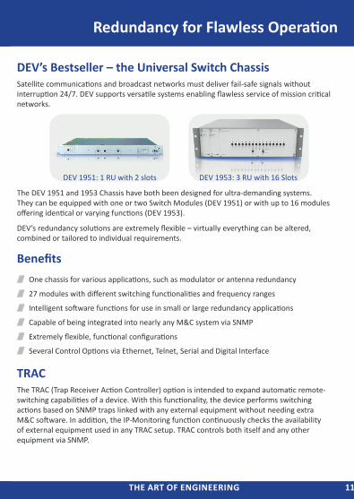
DEV’s Bestseller – the Universal Switch ChassisSatellite communications and broadcast networks must deliver fail-safe signals without interruption 24/7. DEV supports versatile systems enabling flawless service of mission critical networks.
The DEV 1951 and 1953 Chassis have both been designed for ultra-demanding systems. They can be equipped with one or two Switch Modules (DEV 1951) or with up to 16 modules offering identical or varying functions (DEV 1953).
DEV’s redundancy solutions are extremely flexible – virtually everything can be altered, combined or tailored to individual requirements.
Benefits One chassis for various applications, such as modulator or antenna redundancy
27 modules with different switching functionalities and frequency ranges
Intelligent software functions for use in small or large redundancy applications
Capable of being integrated into nearly any M&C system via SNMP
Extremely flexible, functional configurations
Several Control Options via Ethernet, Telnet, Serial and Digital Interface
TRACThe TRAC (Trap Receiver Action Controller) option is intended to expand automatic remote-switching capabilities of a device. With this functionality, the device performs switching actions based on SNMP traps linked with any external equipment without needing extra M&C software. In addition, the IP-Monitoring function continuously checks the availability of external equipment used in any TRAC setup. TRAC controls both itself and any other equipment via SNMP.
DEV 1951: 1 RU with 2 slots DEV 1953: 3 RU with 16 Slots
THE ART OF ENGINEERINGTHE ART OF ENGINEERING12
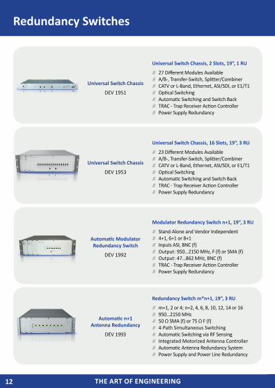
Universal Switch Chassis
DEV 1951
Universal Switch Chassis, 2 Slots, 19“, 1 RU
27 Different Modules Available A/B-, Transfer-Switch, Splitter/Combiner CATV or L-Band, Ethernet, ASI/SDI, or E1/T1 Optical Switching Automatic Switching and Switch Back TRAC - Trap Receiver Action Controller Power Supply Redundancy
Universal Switch Chassis
DEV 1953
Universal Switch Chassis, 16 Slots, 19“, 3 RU
23 Different Modules Available A/B-, Transfer-Switch, Splitter/Combiner CATV or L-Band, Ethernet, ASI/SDI, or E1/T1 Optical Switching Automatic Switching and Switch Back TRAC - Trap Receiver Action Controller Power Supply Redundancy
Automatic ModulatorRedundancy Switch
DEV 1992
Modulator Redundancy Switch n+1, 19“, 3 RU
Stand-Alone and Vendor Independent 4+1, 6+1 or 8+1 Inputs ASI, BNC (f) Output: 950…2150 MHz, F (f) or SMA (f) Output: 47…862 MHz, BNC (f) TRAC - Trap Receiver Action Controller Power Supply Redundancy
Automatic n+1 Antenna Redundancy
DEV 1993
Redundancy Switch m*n+1, 19“, 3 RU
m=1, 2 or 4; n=2, 4, 6, 8, 10, 12, 14 or 16 950…2150 MHz 50 Ω SMA (f) or 75 Ω F (f) 4-Path Simultaneous Switching Automatic Switching via RF Sensing Integrated Motorized Antenna Controller Automatic Antenna Redundancy System Power Supply and Power Line Redundancy
Redundancy Switches
THE ART OF ENGINEERING 13THE ART OF ENGINEERING
Bidirectional Switches
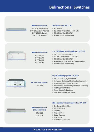
Bidirectional Switch
DEV 1018 (CATV-Band)DEV 10116 (CATV-Band)
DEV 1218 (L-Band)DEV 12116 (L-Band)
De-/Multiplexer, 19“, 1 RU
8:1 and 16:1 10…1006 MHz or 950...2150 MHz 50 Ω SMA (f) or 75 Ω F (f) Power Supply Redundancy
Bidirectional Switch
DEV 1x124DEV 1x132DEV 1x148DEV 1x164
L- or CATV-Band De-/Multiplexer, 19“, 3 RU
24:1, 32:1, 48:1 and 64:1 47…862 MHz or 950...2150 MHz 50 Ω SMA (f) or 75 Ω F (f) Amplifier Module for Loss Compensation Power Supply Redundancy
RF Switching System;
DEV 1400
RF-µW Switching System, 19”, 3 RU
DC…18 GHz, C-, X-, or Ku-Band Individual Switching/Distribution/Combining Customized Functional Modules For Example Redundancy or Matrix Switching Hot-Pluggable Modules Power Supply Redundancy DEV Web Interface and SNMP
Bidirectional Switch (DEV Essentials)
DEV 1228DEV 1236
DEV Essentials Bidirectional Switch, 19“, 1 RU
1:8/8:1 and 1:16/16:1 10…2300 MHz 75 Ω F (f) High Isolation Good Flatness Low Ripple Data Backup Feature
THE ART OF ENGINEERINGTHE ART OF ENGINEERING14
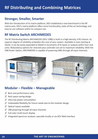
Stronger, Smaller, SmarterWith the introduction of its matrix platform, DEV established a new benchmark in the RF matrix area. DEV’s matrix platform offers more functionality, state-of-the-art technology, and easy-to-use software within its compact size.
RF Matrix Switch ARCHIMEDESThe RF Distributing Matrix ARCHIMEDES (DEV 1986) is built in a high-density, 4 RU chassis. Its superior degree of reliability embodies the core of your system. Available in sizes starting at 16x32, it can be easily expanded to 64x64 in increments of 8 inputs or outputs within four rack units. Redundancy options for channels plus controller are set to maximum reliability. With the LNB Power Option, ARCHIMEDES is capable of powering LNBs through all input channels.
Modular – Flexible – Manageable Best cost-performance ratio Rack space saving design Ultra low power consumption Unbeatable flexibility for future needs due to the modular design Optical Inputs available LNB powering through all input channels Full color multi-touch display Integrated spectrum analyzer, operable locally or via DEV Web Interface
RF Distributing and Combining Matrices
THE ART OF ENGINEERING 15THE ART OF ENGINEERING
RF Distributing and Combining Matrices
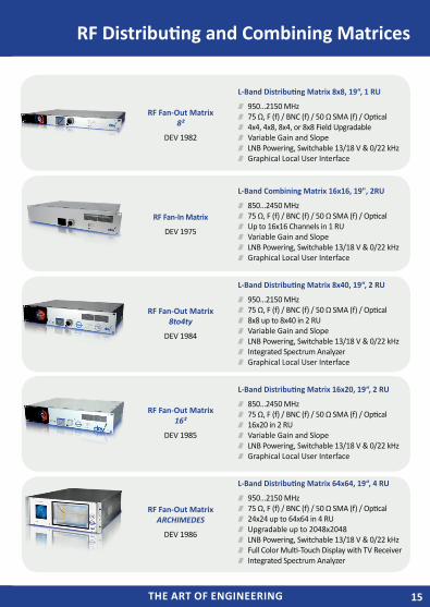
RF Fan-Out Matrix 8²
DEV 1982
L-Band Distributing Matrix 8x8, 19“, 1 RU
950…2150 MHz 75 Ω, F (f) / BNC (f) / 50 Ω SMA (f) / Optical 4x4, 4x8, 8x4, or 8x8 Field Upgradable Variable Gain and Slope LNB Powering, Switchable 13/18 V & 0/22 kHz Graphical Local User Interface
RF Fan-In Matrix
DEV 1975
L-Band Combining Matrix 16x16, 19", 2RU
850…2450 MHz 75 Ω, F (f) / BNC (f) / 50 Ω SMA (f) / Optical Up to 16x16 Channels in 1 RU Variable Gain and Slope LNB Powering, Switchable 13/18 V & 0/22 kHz Graphical Local User Interface
RF Fan-Out Matrix 8to4ty
DEV 1984
L-Band Distributing Matrix 8x40, 19“, 2 RU
950…2150 MHz 75 Ω, F (f) / BNC (f) / 50 Ω SMA (f) / Optical 8x8 up to 8x40 in 2 RU Variable Gain and Slope LNB Powering, Switchable 13/18 V & 0/22 kHz Integrated Spectrum Analyzer Graphical Local User Interface
RF Fan-Out Matrix 16²
DEV 1985
L-Band Distributing Matrix 16x20, 19“, 2 RU
850…2450 MHz 75 Ω, F (f) / BNC (f) / 50 Ω SMA (f) / Optical 16x20 in 2 RU Variable Gain and Slope LNB Powering, Switchable 13/18 V & 0/22 kHz Graphical Local User Interface
RF Fan-Out Matrix ARCHIMEDES
DEV 1986
L-Band Distributing Matrix 64x64, 19“, 4 RU
950…2150 MHz 75 Ω, F (f) / BNC (f) / 50 Ω SMA (f) / Optical 24x24 up to 64x64 in 4 RU Upgradable up to 2048x2048 LNB Powering, Switchable 13/18 V & 0/22 kHz Full Color Multi-Touch Display with TV Receiver Integrated Spectrum Analyzer
THE ART OF ENGINEERINGTHE ART OF ENGINEERING16
RF Distributing Amplifiers, Splitters and CombinersDEV RF Splitters, Combiners and Distributing Amplifiers are built for various frequency ranges, for satellite, CATV and broadband applications. Active and passive devices for various applications and frequency ranges are available in different sizes.
DEV Distribution Amplifiers are capable of splitting an input up to 128 outputs without loss or additional gain, and offer additional features like LNB powering, tilt adjustment, or several redundancy functions. Most of our RF Distribution products come in 19” housings and differ by height, number of channels, distribution functionality, and the integrated software features.
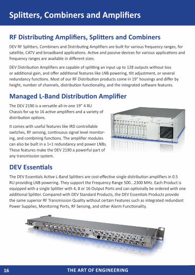
Managed L-Band Distribution AmplifierThe DEV 2190 is a versatile all-in-one 19” 4 RU Chassis for up to 16 active amplifiers and a variety of distribution options.
It comes with useful features like IRD controllable switches, RF sensing, continuous signal level monitor-ing, and combining functions. The amplifier modules can also be built in a 1+1 redundancy and power LNBs. These features make the DEV 2190 a powerful part of any transmission system.
DEV EssentialsThe DEV Essentials Active L-Band Splitters are cost-effective single distribution amplifiers in 0.5 RU providing LNB powering. They support the Frequency Range 500...2300 MHz. Each Product is equipped with a single Splitter with 4, 8 or 16 Output Ports and can optionally be ordered with one additional Splitter. Compared with DEV Standard Products, the DEV Essentials Products provide the same superior RF Transmission Quality without certain Features such as integrated redundant Power Supplies, Monitoring Ports, RF Sensing, and other Alarm Functionality.
Splitters, Combiners and Amplifiers
THE ART OF ENGINEERING 17THE ART OF ENGINEERING
RF Combining and Distribution Systems
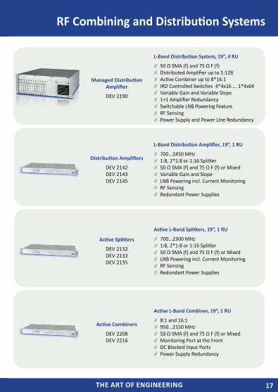
Managed Distribution Amplifier
DEV 2190
L-Band Distribution System, 19”, 4 RU
50 Ω SMA (f) and 75 Ω F (f) Distributed Amplifier up to 1:128 Active Combiner up to 8*16:1 IRD Controlled Switches 4*4x16 ... 1*4x64 Variable Gain and Variable Slope 1+1 Amplifier Redundancy Switchable LNB Powering Feature RF Sensing Power Supply and Power Line Redundancy
Distribution Amplifiers
DEV 2142 DEV 2143 DEV 2145
L-Band Distribution Amplifier, 19”, 1 RU
700...2450 MHz 1:8, 2*1:8 or 1:16 Splitter 50 Ω SMA (f) and 75 Ω F (f) or Mixed Variable Gain and Slope LNB Powering incl. Current Monitoring RF Sensing Redundant Power Supplies
Active Splitters
DEV 2132 DEV 2133 DEV 2135
Active L-Band Splitters, 19”, 1 RU
700...2300 MHz 1:8, 2*1:8 or 1:16 Splitter 50 Ω SMA (f) and 75 Ω F (f) or Mixed LNB Powering incl. Current Monitoring RF Sensing Redundant Power Supplies
Active Combiners
DEV 2208DEV 2216
Active L-Band Combiner, 19“, 1 RU
8:1 and 16:1 950...2150 MHz 50 Ω SMA (f) and 75 Ω F (f) or Mixed Monitoring Port at the Front DC Blocked Input Ports Power Supply Redundancy
THE ART OF ENGINEERINGTHE ART OF ENGINEERING18
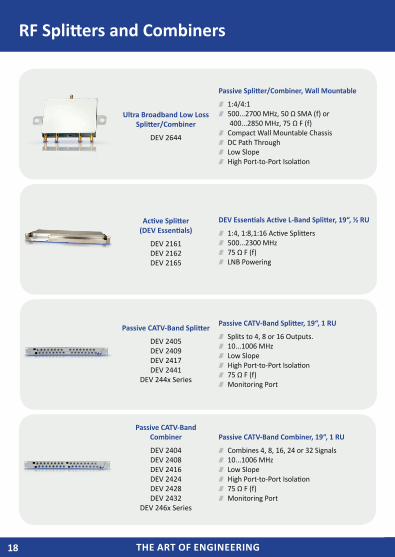
RF Splitters and Combiners
Ultra Broadband Low Loss Splitter/Combiner
DEV 2644
Passive Splitter/Combiner, Wall Mountable
1:4/4:1 500...2700 MHz, 50 Ω SMA (f) or
400...2850 MHz, 75 Ω F (f) Compact Wall Mountable Chassis DC Path Through Low Slope High Port-to-Port Isolation
Active Splitter (DEV Essentials)
DEV 2161DEV 2162DEV 2165
DEV Essentials Active L-Band Splitter, 19“, ½ RU
1:4, 1:8,1:16 Active Splitters 500...2300 MHz 75 Ω F (f) LNB Powering
Passive CATV-Band Splitter
DEV 2405DEV 2409DEV 2417DEV 2441
DEV 244x Series
Passive CATV-Band Splitter, 19“, 1 RU
Splits to 4, 8 or 16 Outputs. 10...1006 MHz Low Slope High Port-to-Port Isolation 75 Ω F (f) Monitoring Port
Passive CATV-Band Combiner
DEV 2404DEV 2408DEV 2416DEV 2424DEV 2428DEV 2432
DEV 246x Series
Passive CATV-Band Combiner, 19“, 1 RU
Combines 4, 8, 16, 24 or 32 Signals 10...1006 MHz Low Slope High Port-to-Port Isolation 75 Ω F (f) Monitoring Port
THE ART OF ENGINEERING 19THE ART OF ENGINEERING
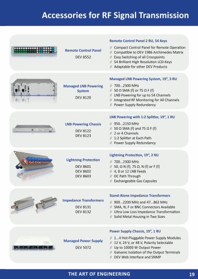
Accessories for RF Signal Transmission
Remote Control Panel
DEV 8552
Remote Control Panel 2 RU, 54 Keys
Compact Control Panel for Remote Operation Compatible to DEV 1986 Archimedes Matrix Easy Switching of all Crosspoints 54 Brilliant High Resolution LCD-Keys Adaptable for other DEV Products
Managed LNB Powering System
DEV 8120
Managed LNB Powering System, 19“, 3 RU
700...2300 MHz 50 Ω SMA (f) or 75 Ω F (f) LNB Powering for up to 54 Channels Integrated RF Monitoring for All Channels Power Supply Redundancy
LNB Powering Chassis
DEV 8122DEV 8123
LNB Powering with 1:2 Splitter, 19“, 1 RU
950...2150 MHz 50 Ω SMA (f) and 75 Ω F (f) 2 or 4 Channels 1:2 Splitter at Each Path Power Supply Redundancy
Lightning Protection
DEV 8601DEV 8602DEV 8603
Lightning Protection, 19“, 2 RU
700...2300 MHz 50, Ω N (f), 75 Ω, N (f) or F (f) 4, 8 or 12 LNB Feeds DC Path Through Exchangeable Gas Capsules
Impedance Transformers
DEV 8131DEV 8132
Stand-Alone Impedance Transformers
900...2200 MHz and 47...862 MHz SMA, N, F or BNC Connectors Available Ultra Low Loss Impedance Transformation Solid Metal Housing in Two Sizes
Managed Power Supply
DEV 5072
Power Supply Chassis, 19“, 1 RU
1...4 Hot-Pluggable Power Supply Modules 12 V, 24 V, or 48 V, Polarity Selectable Up to 10000 W Output Power Galvanic Isolation of the Output Terminals DEV Web Interface and SNMP
THE ART OF ENGINEERINGTHE ART OF ENGINEERING20
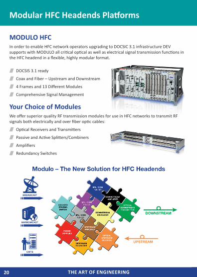
MODULO HFCIn order to enable HFC network operators upgrading to DOCSIC 3.1 infrastructure DEV supports with MODULO all critical optical as well as electrical signal transmission functions in the HFC headend in a flexible, highly modular format.
DOCSIS 3.1 ready
Coax and Fiber – Upstream and Downstream
4 Frames and 13 Different Modules
Comprehensive Signal Management
Your Choice of ModulesWe offer superior quality RF transmission modules for use in HFC networks to transmit RF signals both electrically and over fiber optic cables:
Optical Receivers and Transmitters
Passive and Active Splitters/Combiners
Amplifiers
Redundancy Switches
Modular HFC Headends Platforms
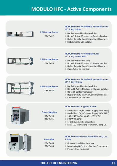
THE ART OF ENGINEERING 21THE ART OF ENGINEERING
2 RU Active Frame
DEV 3482
MODULO Frame for Active & Passive Modules 19“, 2 RU, 7 Slots
For Active and Passive Modules Up to 3 Active Modules + 4 Passive Modules Higher Density than Conventional Products Redundant Power Supplies
3 RU Active Frame
DEV 3483
MODULO Frame for Active Modules19“, 3 RU, 22 Half Slots
For Active Modules only Up to 8 Active Modules + 2 Power Supplies Higher Density than Conventional Products Cable Relief on the Rear
5 RU Active Frame
DEV 3480
MODULO Frame for Active & Passive Modules 19“, 5 RU, 22 Slots
For Active and Passive Modules Up to 18 Active Modules + 2 Power Supplies Up to 66 Splitter/Combiner Higher Density than Conventional Products Cable Relief on the Rear
Power Supplies
DEV 3490DEV 3491
MODULO Power Supplies, 3 Slots
Available as AC/DC Power Supply (DEV 3490) Available as DC/DC Power Supply (DEV 3491) 100…240 V AC or +/-36…+/-72 V DC 220 W @ 45 °C 1+1 Redundant Configuration Local LED Monitoring (Prime OK, Temp OK)
Controller
DEV 3464DEV 3465
MODULO Controller for Active Modules, 1 or 3 Slots
Optional Local User Interface Monitoring & Control of Active Components Prepared for Clustering
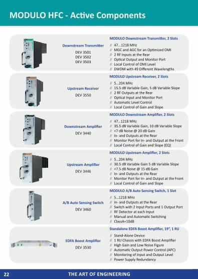
MODULO HFC - Active Components
THE ART OF ENGINEERINGTHE ART OF ENGINEERING22
Downstream Transmitter
DEV 3501DEV 3502DEV 3503
MODULO Downstream Transmitter, 2 Slots
47...1218 MHz MGC and AGC for an Optimized OMI 2 RF Inputs at the Rear Optical Output and Monitor Port Local Control of OMI Level DWDM with 49 Different Wavelengths
Upstream Receiver
DEV 3550
MODULO Upstream Receiver, 2 Slots
5…204 MHz 15.5 dB Variable Gain, 5 dB Variable Slope 2 RF Outputs at the Rear Optical Input and Monitor Port Automatic Level Control Local Control of Gain and Slope
Downstream Amplifier
DEV 3440
MODULO Downstream Amplifier, 2 Slots
47…1218 MHz 35.5 dB Variable Gain, 10 dB Variable Slope <7 dB Noise @ 20 dB Gain In- and Outputs at the Rear Monitor Port for In- and Output at the Front Local Control of Gain and Slope (EQ)
Upstream Amplifier
DEV 3446
MODULO Upstream Amplifier, 2 Slots
5…204 MHz 30.5 dB Variable Gain 5 dB Variable Slope <7.5 dB Noise @ 15 dB Gain In- and Outputs at the Rear Monitor Port for In- and Output at the Front Local Control of Gain and Slope
A/B Auto Sensing Switch
DEV 3460
MODULO A/B Auto Sensing Switch, 1 Slot
5…1218 MHz In- and Outputs at the Rear Switch with 2 Input Ports and 1 Output Port RF Detector at each Input Manual and Automatic Switching ClassA+10dB
EDFA Boost Amplifier
DEV 3530
Standalone EDFA Boost Amplifier, 19“, 1 RU
Stand-Alone Device 1 RU Chassis with EDFA Boost Amplifier High Gain and Low Noise Figure Automatic Output Power Control (APC) Monitoring of Input and Output Level Power Supply Redundancy
MODULO HFC - Active Components
THE ART OF ENGINEERING 23THE ART OF ENGINEERING
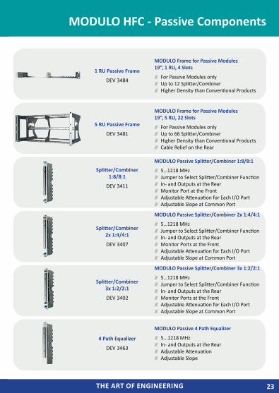
1 RU Passive Frame
DEV 3484
MODULO Frame for Passive Modules19“, 1 RU, 4 Slots
For Passive Modules only Up to 12 Splitter/Combiner Higher Density than Conventional Products
5 RU Passive Frame
DEV 3481
MODULO Frame for Passive Modules19“, 5 RU, 22 Slots
For Passive Modules only Up to 66 Splitter/Combiner Higher Density than Conventional Products Cable Relief on the Rear
Splitter/Combiner1:8/8:1
DEV 3411
MODULO Passive Splitter/Combiner 1:8/8:1
5…1218 MHz Jumper to Select Splitter/Combiner Function In- and Outputs at the Rear Monitor Port at the Front Adjustable Attenuation for Each I/O Port Adjustable Slope at Common Port
Splitter/Combiner2x 1:4/4:1
DEV 3407
MODULO Passive Splitter/Combiner 2x 1:4/4:1
5…1218 MHz Jumper to Select Splitter/Combiner Function In- and Outputs at the Rear Monitor Ports at the Front Adjustable Attenuation for Each I/O Port Adjustable Slope at Common Port
Splitter/Combiner3x 1:2/2:1
DEV 3402
MODULO Passive Splitter/Combiner 3x 1:2/2:1
5…1218 MHz Jumper to Select Splitter/Combiner Function In- and Outputs at the Rear Monitor Ports at the Front Adjustable Attenuation for Each I/O Port Adjustable Slope at Common Port
4 Path Equalizer
DEV 3463
MODULO Passive 4 Path Equalizer
5...1218 MHz In- and Outputs at the Rear Adjustable Attenuation Adjustable Slope
MODULO HFC - Passive Components
THE ART OF ENGINEERINGTHE ART OF ENGINEERING24
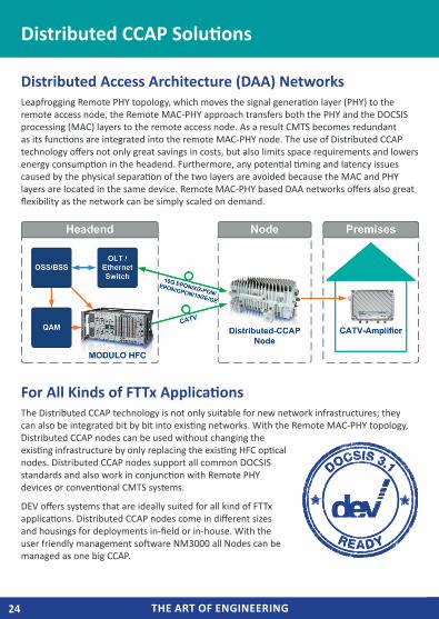
Distributed Access Architecture (DAA) NetworksLeapfrogging Remote PHY topology, which moves the signal generation layer (PHY) to the remote access node, the Remote MAC-PHY approach transfers both the PHY and the DOCSIS processing (MAC) layers to the remote access node. As a result CMTS becomes redundant as its functions are integrated into the remote MAC-PHY node. The use of Distributed CCAP technology offers not only great savings in costs, but also limits space requirements and lowers energy consumption in the headend. Furthermore, any potential timing and latency issues caused by the physical separation of the two layers are avoided because the MAC and PHY layers are located in the same device. Remote MAC-PHY based DAA networks offers also great flexibility as the network can be simply scaled on demand.
For All Kinds of FTTx ApplicationsThe Distributed CCAP technology is not only suitable for new network infrastructures; they can also be integrated bit by bit into existing networks. With the Remote MAC-PHY topology, Distributed CCAP nodes can be used without changing the existing infrastructure by only replacing the existing HFC optical nodes. Distributed CCAP nodes support all common DOCSIS standards and also work in conjunction with Remote PHY devices or conventional CMTS systems.
DEV offers systems that are ideally suited for all kind of FTTx applications. Distributed CCAP nodes come in different sizes and housings for deployments in-field or in-house. With the user friendly management software NM3000 all Nodes can be managed as one big CCAP.
Distributed CCAP Solutions
THE ART OF ENGINEERING 25THE ART OF ENGINEERING
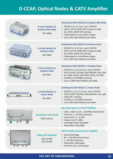
D-CCAP DOCSIS 3.0 Outdoor Mini Node
DEV 6860
Distributed CCAP DOCSIS 3.0 Outdoor Mini Node
DOCSIS 3.0, 2.0, Euro- and C-DOCSIS 42/54, 55/70, 65/87 MHz Frequency Split GE, EPON, GPON SFP Interface Cable-based or Local Power Supply Up to 250 Cable Modems per Node
D-CCAP DOCSIS 3.0 Outdoor Node
DEV 6850
Distributed CCAP DOCSIS 3.0 Outdoor Node
DOCSIS 3.0, 2.0, Euro- and C-DOCSIS 42/54, 55/70, 65/87 MHz Frequency Split GE, EPON, GPON SFP Interface Cable-based or Local Power Supply Up to 500 Cable Modems per Node
D-CCAP DOCSIS 3.1 Outdoor Node
DEV 6871
Distributed CCAP DOCSIS 3.1 Outdoor Node
DOCSIS 3.1, 3.0, 2.0, Euro- and C-DOCSIS 42/54, 65/87, 85/108, 204/258 MHz Freq. Split GE, 10GE, EPON, 10G EPON, GPON, XG-PON 6 OFDM, 2*2 OFDMA Channels Up to 1,000 Cable Modems per Node
D-CCAP DOCSIS 3.1 Indoor Node
DEV 6811
Distributed CCAP DOCSIS 3.1 Indoor Node
DOCSIS 3.1, 3.0, 2.0, Euro- and C-DOCSIS 42/54, 65/87, 85/108, 204/258 MHz Freq. Split 10GE SFP+ Interface 6 OFDM, 2*2 OFDMA Channels Up to 500 Cable Modems per Node
Axing Micro Fibre Node
ONX 1550-01
Mico Fibre Node for FTTH/FTTB/RFoG
1540...1560 nm, 85...1218 MHz Downstream 1310 nm, 5...65 MHz Upstream Input Level -8...+1 dBm Output Level +3 dBm Interstage Slope Adjustable Attenuation Adjustable
Axing CATV Amplifier
BVS 14-69P BVS 20-69P
CATV Amplifier premium-line 1218MHz
GaAs technology 85...1218 MHz Downstream 5...65 MHz Upstream Attenuation Adjustable Test Ports at In- and Output
D-CCAP, Optical Nodes & CATV Amplifier
THE ART OF ENGINEERINGTHE ART OF ENGINEERING26
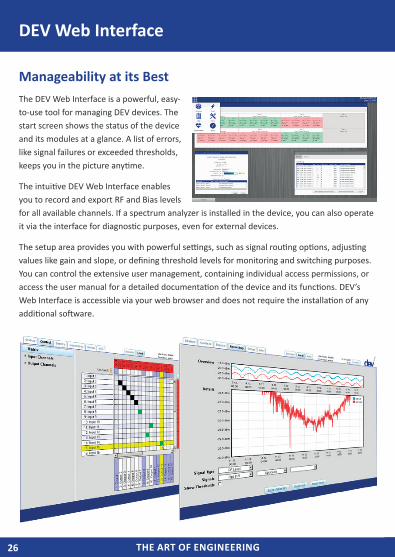
DEV Web Interface
Manageability at its BestThe DEV Web Interface is a powerful, easy-to-use tool for managing DEV devices. The start screen shows the status of the device and its modules at a glance. A list of errors, like signal failures or exceeded thresholds, keeps you in the picture anytime.
The intuitive DEV Web Interface enables you to record and export RF and Bias levels for all available channels. If a spectrum analyzer is installed in the device, you can also operate it via the interface for diagnostic purposes, even for external devices.
The setup area provides you with powerful settings, such as signal routing options, adjusting values like gain and slope, or defining threshold levels for monitoring and switching purposes. You can control the extensive user management, containing individual access permissions, or access the user manual for a detailed documentation of the device and its functions. DEV’s Web Interface is accessible via your web browser and does not require the installation of any additional software.
THE ART OF ENGINEERING 27THE ART OF ENGINEERING
DEV TripleC ProtectionDEV offers a Support package for all our high quality and high availability products that is unrivaled in the market, and raises the bar above industry standards: The TripleC Protection
From installation to ongoing deployment – the qualified technical DEV staff will support you with the best and fastest solution. You will enjoy the advantage of our outstanding support services for more than three years, free of charge:
37 Months Service Period
Direct Access to Technical Support
Guaranteed Service Levels
3-hour Reaction Time1
Start of Fault Analysis within 24 hours1
Free Shipping of Equipment for Repair – Back and Forth
Free of Charge
Extendable to a total service term of 10 years
DEV Premium ServiceFor high-availability applications, the optional DEV Premium Service gives you full protection on top of TripleC. It offers a free replacement unit in advance in case of a failure, free firmware updates and a guaranteed start of the fault analysis in less than eight hours1. Our Premium Service can be ordered even after delivery of your equipment. The Premium Service requires DEV TripleC protection.
7 Years Warranty – We Trust our ProductsSince we develop and manufacture our state-of-the-art products in-house, we can be absolutely sure that they are durable and have the highest reliability and lifetime. By offering a long lasting 7-year warranty for all standard products2 we promise that our devices are engineered and manufactured for many years of use.1Working days, Monday - Friday 8:00am - 6:00pm CET2Excluded are all mechanical parts and power supplies
DEV Services
DEV Systemtechnik GmbH
Grüner Weg 4AD-61169 FriedbergGermany
Phone: +49(0) 60 31/6975 100Fax: +49(0) 60 31/6975 [email protected]
© DEV Systemtechnik · 01/2019
DEV Systemtechnik, part of the AXING Group, develops and manu-factures a complete range of products and systems for optical and electrical transmission of Radio Frequency (RF) signals via coaxial cable or fiber. For over 20 years DEV has designed, engineered, and manufactured RF transmission equipment for satellite, broadcast, and cable applications. All products are built to meet the highest standards of system availability, reliability and manageability.
In the DEV Pocket Guide you will find...
RF over Fiber Solutions Switching Systems Amplifiers, Splitters & Combiners Accessories for Broadcast & SatCom DOCSIS 3.1 Equipment for HFC and FTTx Networks Information about our services and our 7-year warranty
POCKET GUIDE