Embed Size (px)
Citation preview
SUPPORTSILL
POCKET INTERIOR
SHADE-MOUNT SIDE
SUPPORTSILL
POCKET INTERIOR
SHADE-MOUNT SIDE
POCKETCEILING
POCKETCEILING
SAFEWIREWAY
PROFILE VIEW
SHADEHOOK
PROFILE VIEW PROFILE VIEW
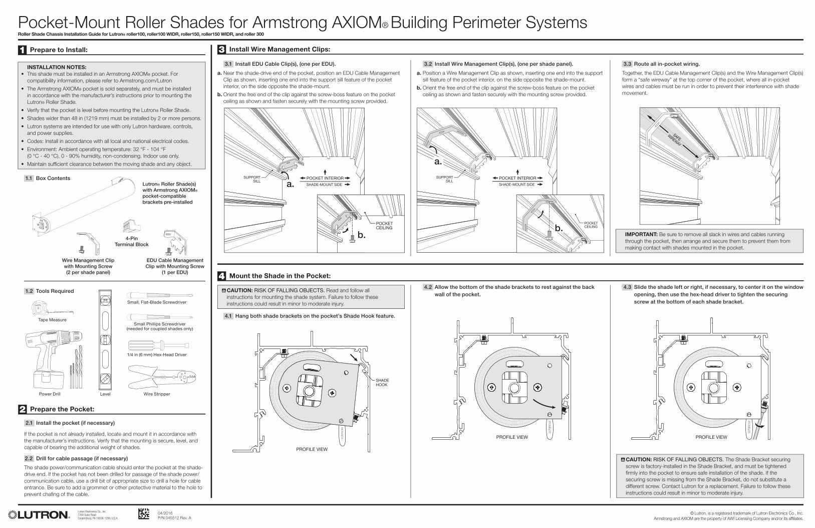
Pocket-Mount Roller Shades for Armstrong AXIOM® Building Perimeter SystemsRoller Shade Chassis Installation Guide for Lutron® roller100, roller100 WIDR, roller150, roller150 WIDR, and roller 300
Lutron Electronics Co., Inc.7200 Suter RoadCoopersburg, PA 18036-1299, U.S.A.
04/2016P/N 045512 Rev. A
O Lutron, is a registered trademark of Lutron Electronics Co., Inc. Armstrong and AXIOM are the property of AWI Licensing Company and/or its affiliates.
Lutron® Roller Shade(s) with Armstrong AXIOM® pocket-compatible brackets pre-installed
Wire Management Clipwith Mounting Screw(2 per shade panel)
4-PinTerminal Block
EDU Cable Management Clip with Mounting Screw
(1 per EDU)
2 Prepare the Pocket:
3 Install Wire Management Clips:
4 Mount the Shade in the Pocket:
1 Prepare to Install:
! CAUTION: RISK OF FALLING OBJECTS. Read and follow all instructions for mounting the shade system. Failure to follow these instructions could result in minor to moderate injury.
! CAUTION: RISK OF FALLING OBJECTS. The Shade Bracket securing screw is factory-installed in the Shade Bracket, and must be tightened fi rmly into the pocket to ensure safe installation of the shade. If the securing screw is missing from the Shade Bracket, do not substitute a different screw. Contact Lutron for a replacement. Failure to follow these instructions could result in minor to moderate injury.
1/4 in (6 mm) Hex-Head Driver
Wire StripperLevel
Small Phillips Screwdriver(needed for coupled shades only)
Small, Flat-Blade Screwdriver
Power Drill
Tape Measure
1.1 Box Contents
2.1 Install the pocket (if necessary)
1.2 Tools Required
INSTALLATION NOTES:• This shade must be installed in an Armstrong AXIOM® pocket. For
compatibility information, please refer to Armstrong.com/Lutron
• The Armstrong AXIOM® pocket is sold separately, and must be installed in accordance with the manufacturer’s instructions prior to mounting the Lutron® Roller Shade.
• Verify that the pocket is level before mounting the Lutron® Roller Shade.
• Shades wider than 48 in (1219 mm) must be installed by 2 or more persons.
• Lutron systems are intended for use with only Lutron hardware, controls, and power supplies.
• Codes: Install in accordance with all local and national electrical codes.
• Environment: Ambient operating temperature: 32 °F - 104 °F (0 °C - 40 °C), 0 - 90% humidity, non-condensing. Indoor use only.
• Maintain suffi cient clearance between the moving shade and any object.
IMPORTANT: Be sure to remove all slack in wires and cables running through the pocket, then arrange and secure them to prevent them from making contact with shades mounted in the pocket.
3.1 Install EDU Cable Clip(s), (one per EDU).
a. Near the shade-drive end of the pocket, position an EDU Cable Management Clip as shown, inserting one end into the support sill feature of the pocket interior, on the side opposite the shade-mount.
b. Orient the free end of the clip against the screw-boss feature on the pocket ceiling as shown and fasten securely with the mounting screw provided.
3.2 Install Wire Management Clip(s), (one per shade panel).
a. Position a Wire Management Clip as shown, inserting one end into the support sill feature of the pocket interior, on the side opposite the shade-mount.
b. Orient the free end of the clip against the screw-boss feature on the pocket ceiling as shown and fasten securely with the mounting screw provided.
3.3 Route all in-pocket wiring.
Together, the EDU Cable Management Clip(s) and the Wire Management Clip(s) form a “safe wireway” at the top corner of the pocket, where all in-pocket wires and cables must be run in order to prevent their interference with shade movement.
4.1 Hang both shade brackets on the pocket’s Shade Hook feature.
4.2 Allow the bottom of the shade brackets to rest against the back wall of the pocket.
4.3 Slide the shade left or right, if necessary, to center it on the window opening, then use the hex-head driver to tighten the securing screw at the bottom of each shade bracket.
If the pocket is not already installed, locate and mount it in accordance with the manufacturer’s instructions. Verify that the mounting is secure, level, and capable of bearing the additional weight of shades.
2.2 Drill for cable passage (if necessary)
The shade power/communication cable should enter the pocket at the shade-drive end. If the pocket has not been drilled for passage of the shade power/communication cable, use a drill bit of appropriate size to drill a hole for cable entrance. Be sure to add a grommet or other protective material to the hole to prevent chafi ng of the cable.
a.
a.
b.b.
Holes
CouplerShaft
Coupler Shaft
VIEW FROM BELOW POCKET
Drive Shade
Coupled Shade
Shaft
CouplerScrew Cap
Tab PROFILE VIEW OFASEMBLED COUPLING
CouplerShaft
Tab
Shaft
PROFILE VIEW
Coupler HubSet Screws
Drive Shade
Coupled Shade
4-Pin Terminal Block
From EDU
POCKET ANDWIRES OMITTED
FOR CLARITY
EDU Wire Management Clip(mounted in pocket; see step 3.1)
EDU Connector
LevelingScrew
Lutron Electronics Co., Inc.7200 Suter RoadCoopersburg, PA 18036-1299, U.S.A.
04/2016P/N 045512 Rev. A
O Lutron, is a registered trademark of Lutron Electronics Co., Inc. Armstrong and AXIOM are the property of AWI Licensing Company and/or its affiliates.
Roller Shade Chassis Installation Guide for Lutron® roller100, roller100 WIDR, roller150, roller150 WIDR, and roller 300 Page 2
6 Wire the 4-Pin Terminal Block:
5 Verify the Shade is Level: 9 Installation of Coupled Shades:
6.1 Prepare the Cable
a. Strip 2 in (51 mm) of outer jacket off cable coming from the wall.
b. Strip 1⁄4 in (6 mm) insulation off each individual wire.(4-conductor cable shown. Number and colors of conductors may vary.)
6.2 Wire the 4-Pin Terminal Block
Wire 4-pin terminal block (provided) to cable using a small, fl at-blade screwdriver to tighten screws securely on the exposed wire. Leave 1/16 in (2 mm) of exposed conductor to ensure insulation is not pinched.
NOTE: Terminals 3 and 4 are for wired communication only, and are not used in wireless control installations.
Com
V +
MUX
MUX
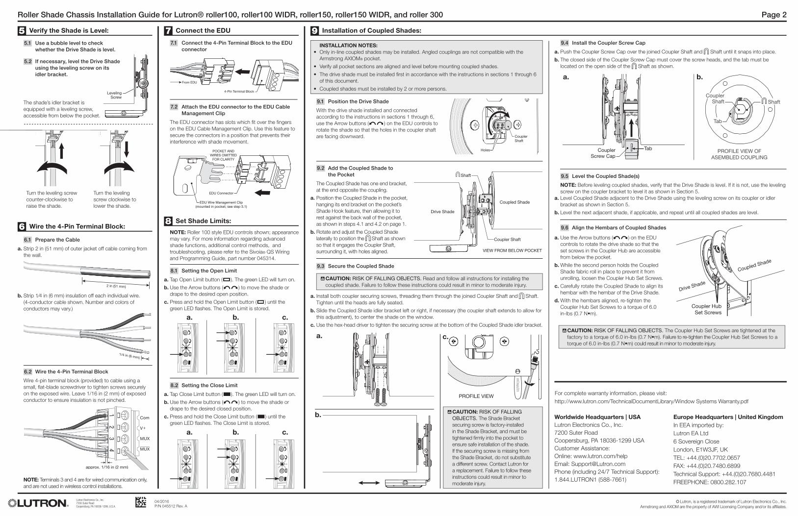
9.1 Position the Drive Shade
With the drive shade installed and connected according to the instructions in sections 1 through 6, use the Arrow buttons ( ) on the EDU controls to rotate the shade so that the holes in the coupler shaft are facing downward.
9.3 Secure the Coupled Shade
5.1 Use a bubble level to check whether the Drive Shade is level.
5.2 If necessary, level the Drive Shade using the leveling screw on its idler bracket.
9.4 Install the Coupler Screw Cap
a. Push the Coupler Screw Cap over the joined Coupler Shaft and Shaft until it snaps into place.
b. The closed side of the Coupler Screw Cap must cover the screw heads, and the tab must be located on the open side of the Shaft as shown.
9.2 Add the Coupled Shade to the Pocket
The Coupled Shade has one end bracket, at the end opposite the coupling.
a. Position the Coupled Shade in the pocket, hanging its end bracket on the pocket’s Shade Hook feature, then allowing it to rest against the back wall of the pocket, as shown in steps 4.1 and 4.2 on page 1.
b. Rotate and adjust the Coupled Shade laterally to position the Shaft as shown so that it engages the Coupler Shaft, surrounding it, with holes aligned.
INSTALLATION NOTES:• Only in-line coupled shades may be installed. Angled couplings are not compatible with the
Armstrong AXIOM® pocket.
• Verify all pocket sections are aligned and level before mounting coupled shades.
• The drive shade must be installed fi rst in accordance with the instructions in sections 1 through 6 of this document.
• Coupled shades must be installed by 2 or more persons.
9.6 Align the Hembars of Coupled Shades
Worldwide Headquarters | USALutron Electronics Co., Inc.7200 Suter RoadCoopersburg, PA 18036-1299 USACustomer Assistance:Online: www.lutron.com/helpEmail: [email protected] (including 24/7 Technical Support):1.844.LUTRON1 (588-7661)
Europe Headquarters | United KingdomIn EEA imported by:Lutron EA Ltd6 Sovereign CloseLondon, E1W3JF, UKTEL: +44.(0)20.7702.0657FAX: +44.(0)20.7480.6899Technical Support: +44.(0)20.7680.4481FREEPHONE: 0800.282.107
For complete warranty information, please visit:http://www.lutron.com/TechnicalDocumentLibrary/Window Systems Warranty.pdf
a. c.
b.
a. b.
! CAUTION: RISK OF FALLING OBJECTS. Read and follow all instructions for installing the coupled shade. Failure to follow these instructions could result in minor to moderate injury.
! CAUTION: RISK OF FALLING OBJECTS. The Coupler Hub Set Screws are tightened at the factory to a torque of 6.0 in-lbs (0.7 N•m). Failure to re-tighten the Coupler Hub Set Screws to a torque of 6.0 in-lbs (0.7 N•m) could result in minor to moderate injury.
! CAUTION: RISK OF FALLING OBJECTS. The Shade Bracket securing screw is factory-installed in the Shade Bracket, and must be tightened fi rmly into the pocket to ensure safe installation of the shade. If the securing screw is missing from the Shade Bracket, do not substitute a different screw. Contact Lutron for a replacement. Failure to follow these instructions could result in minor to moderate injury.
a. Install both coupler securing screws, threading them through the joined Coupler Shaft and Shaft. Tighten until the heads are fully seated.
b. Slide the Coupled Shade idler bracket left or right, if necessary (the coupler shaft extends to allow for this adjustment), to center the shade on the window.
c. Use the hex-head driver to tighten the securing screw at the bottom of the Coupled Shade idler bracket.
a. Use the Arrow buttons ( ) on the EDU controls to rotate the drive shade so that the set screws in the Coupler Hub are accessible from below the pocket.
b. While the second person holds the Coupled Shade fabric roll in place to prevent it from unrolling, loosen the Coupler Hub Set Screws.
c. Carefully rotate the Coupled Shade to align its hembar with the hembar of the Drive Shade.
d. With the hembars aligned, re-tighten the Coupler Hub Set Screws to a torque of 6.0 in-lbs (0.7 N•m).
Turn the leveling screw counter-clockwise to raise the shade.
Turn the leveling screw clockwise to lower the shade.
9.5 Level the Coupled Shade(s)
NOTE: Before leveling coupled shades, verify that the Drive Shade is level. If it is not, use the leveling screw on the coupler bracket to level it as shown in Section 5.
a. Level Coupled Shade adjacent to the Drive Shade using the leveling screw on its coupler or idler bracket as shown in Section 5.
b. Level the next adjacent shade, if applicable, and repeat until all coupled shades are level.
8 Set Shade Limits:
7 Connect the EDU
7.1 Connect the 4-Pin Terminal Block to the EDU connector
7.2 Attach the EDU connector to the EDU Cable Management Clip
The EDU connector has slots which fi t over the fi ngers on the EDU Cable Management Clip. Use this feature to secure the connectors in a position that prevents their interference with shade movement.
NOTE: Roller 100 style EDU controls shown; appearance may vary. For more information regarding advanced shade functions, additional control methods, and troubleshooting, please refer to the Sivoia® QS Wiring and Programming Guide, part number 045314.
8.1 Setting the Open Limit
a. Tap Open Limit button ( ). The green LED will turn on.
b. Use the Arrow buttons ( ) to move the shade or drape to the desired open position.
c. Press and hold the Open Limit button ( ) until the green LED fl ashes. The Open Limit is stored.
8.2 Setting the Close Limit
a. Tap Close Limit button ( ). The green LED will turn on.
b. Use the Arrow buttons ( ) to move the shade or drape to the desired closed position.
c. Press and hold the Close Limit button ( ) until the green LED fl ashes. The Close Limit is stored.
a. b. c.
The shade’s idler bracket is equipped with a leveling screw, accessible from below the pocket.
a. b. c.


![ENCORE AWNING OPERATOR (SILL MOUNT) · encore™ awning operator (sill mount) 26ff [12.77 mm].500 hardware shown for left hand window, see fig.1 part number description 11577.xx track](https://img.pdfslide.net/doc/110x75/6014fa7de3119409c2481f2e/encore-awning-operator-sill-mount-encorea-awning-operator-sill-mount-26ff.jpg)