Embed Size (px)
Citation preview
PointSense Plant
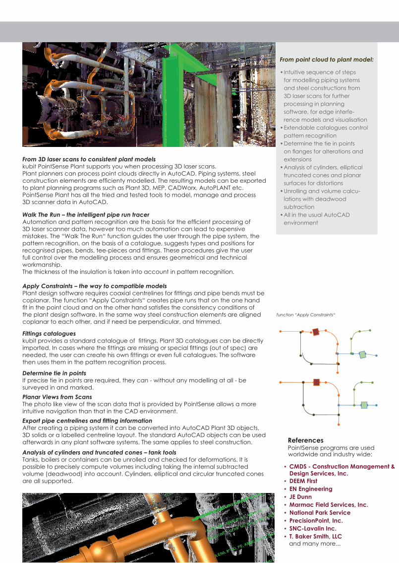
function “Apply Constraints“
From 3D laser scans to consistent plant modelskubit PointSense Plant supports you when processing 3D laser scans.Plant planners can process point clouds directly in AutoCAD. Piping systems, steel construction elements are efcienty modelled. The resulting models can be exported to plant planning programs such as Plant 3D, MEP, CADWorx, AutoPLANT etc. PointSense Plant has all the tried and tested tools to model, manage and process 3D scanner data in AutoCAD.
Walk The Run – the intelligent pipe run tracerAutomation and pattern recognition are the basis for the efcient processing of 3D laser scanner data, however too much automation can lead to expensive mistakes. The “Walk The Run“ function guides the user through the pipe system, the pattern recognition, on the basis of a catalogue, suggests types and positions for recognised pipes, bends, tee-pieces and ttings. These procedures give the user full control over the modelling process and ensures geometrical and technical workmanship. The thickness of the insulation is taken into account in pattern recognition.
Apply Constraints – the way to compatible modelsPlant design software requires coaxial centrelines for ttings and pipe bends must be coplanar. The function “Apply Constraints“ creates pipe runs that on the one hand t in the point cloud and on the other hand satises the consistency conditions of the plant design software. In the same way steel construction elements are aligned coplanar to each other, and if need be perpendicular, and trimmed.
Fittings catalogueskubit provides a standard catalogue of ttings. Plant 3D catalogues can be directly imported. In cases where the ttings are missing or special ttings (out of spec) are needed, the user can create his own ttings or even full catalogues. The software then uses them in the pattern recognition process.
Determine tie in pointsIf precise tie in points are required, they can - without any modelling at all - be surveyed in and marked.
Planar Views from ScansThe photo like view of the scan data that is provided by PointSense allows a more intuitive navigation than that in the CAD environment.
Export pipe centrelines and tting informationAfter creating a piping system it can be converted into AutoCAD Plant 3D objects, 3D solids or a labelled centreline layout. The standard AutoCAD objects can be used afterwards in any plant software systems. The same applies to steel construction.
Analysis of cylinders and truncated cones – tank toolsTanks, boilers or containers can be unrolled and checked for deformations. It is possible to precisely compute volumes including taking the internal subtracted volume (deadwood) into account. Cylinders, elliptical and circular truncated cones are all supported.
From point cloud to plant model:
Intuitive sequence of steps •
for modelling piping systems
and steel constructions from
3D laser scans for further
processing in planning
software, for edge interfe-
rence models and visualisation
Extendable catalogues control •
pattern recognition
Determine the tie in points •
on anges for alterations and
extensions
Analysis of cylinders, elliptical •
truncated cones and planar
surfaces for distortions
Unrolling and volume calcu-•
lations with deadwood
subtraction
All in the usual AutoCAD •
environment
CMDS - Construction Management & ▪
DEEM First ▪
EN Engineering ▪
JE Dunn ▪
Marmac Field Services, Inc. ▪
National Park Service ▪
PrecisionPoint, Inc. ▪
SNC-Lavalin Inc. ▪
T. Baker Smith, LLC ▪ and many more...
Design Services, Inc.
ReferencesPointSense programs are used worldwide and industry wide:
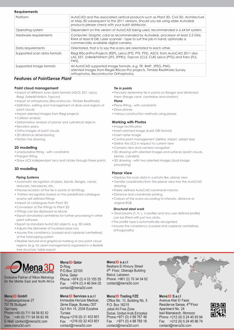
Requirements
Platform AutoCAD and the associated vertical products such as Plant 3D, Civil 3D, Architecture or Map 3D subsequent to the 2011 versions. Should you be using older Autodesk products please check with your kubit distributor.
Operating system Dependent on the version of AutoCAD being used, recommended is a 64 bit system.
Hardware requirements Computer: Graphic card as recommended by Autodesk, processor at least 2.5 GHz,RAM at least 8 GB; Laser scanner - type to suit the job in hand; optionally a commercially available digital camera.
Data requirements Orientated, that is to say the scans are orientated to each other.
Supported scan data formats Riegl RiScanPro-Projects (RSP), Leica (PTZ, PTS, PTX), ASCII, from AutoCAD 2011 also LAS, E57, Zoller&Fröhlich (ZFS, ZFPRJ), Topcon (CL3, CLR) Leica (PTG) and Faro (FLS, FWS).
Supported image formats All AutoCAD supported image formats, e.g. TIF, BMP, JPEG, PNG,oriented images from Riegel RiScan-Pro projects, Trimble RealWorks Survey orthophotos, Reconstructor Orthophotos.
Features of PointSense Plant
Point cloud management Import of different scan data formats (ASCII, E57, Leica, •
Riegl, Zoller&Fröhlich, Topcon)
Import of orthophotos (Reconstructor, Trimble RealWorks)•
Denition, editing and management of slices and regions of •
point clouds
Import oriented images from Riegl projects•
Collision analysis•
Deformation analysis of planar and cylindrical objects•
Elevation plans•
Ortho images of point clouds•
3D distance dimensioning•
Flatten the drawing•
2D modellingLine/polyline tting - with constraints•
Polygon tting•
Draw UCS independant arcs and circles through three points •
3D modelling
Piping Systems
Automatic recognition of pipes, bends, anges, valves, •
reducers, tee-pieces, etc.
Precise location of the tie in points of all ttings•
Pattern recognition based on the predened catalogue •
and/or self dened ttings
Import of catalogues from Plant 3D•
Conversion of the ttings to Plant 3D•
Fittings can be displayed as blocks•
Export annotated centrelines for further processing in other •
plant software
Export as standard AutoCAD objects, e.g. 3D solids•
Adjusts the diameter of insulated pipe runs•
Assures the consistency (coaxial and coplanar centrelines) •
of the total piping system
Flexible textural and graphical marking of any point cloud •
regions (e.g. for asset management);organised in a exible
tree structure; table export
Structural steel work
Steel beams (T, H, L, U proles and any user dened prole)•
can be tted with just two clicks.
The prole type is automatically recognised.•
Assures the consistency (coaxial and coplanar centrelines, •
orthogonality)
Tie in points
Precisely determine tie in points on anges and dimension •
them (ange centr, centreline and rotation)
Plane
Plane tting - with constraints•
Draw planes•
Various construction methods using planes•
Working with PhotosImage rectication•
Insert oriented image (kubit ORI format)•
Insert raster image•
Control point management (dene, import, adapt size)•
Dene the UCS in respect to current view•
Camera view and camera navigation•
3D drawing with oriented images and surfaces (point clouds, •
planes, cylinders)
3D drawing - with two oriented images (dual image •
processing)
Planar ViewDisplays the scan data in a photo like, planar view•
Transfer coordinates from the planar view into the AutoCAD •
drawing
Freely dened AutoCAD command macros•
Distance and coordinate picking•
Colours of the scans according to intensity, distance or •
original RGB