Embed Size (px)
Citation preview
Pololu Jrk USB Motor ControllerUser's Guide
Pololu Jrk USB Motor Controller User's Guide © 2001–2014 Pololu Corporation
http://www.pololu.com/docs/0J38/all Page 1 of 45
1. Overview . . . . . . . . . . . . . . . . . . . . . . . . . . . . . . . . . . . . . . . . . . . . . . . . . . . . . . 31.a. Module Pinout and Components . . . . . . . . . . . . . . . . . . . . . . . . . . . . . . . . . . . . . . 51.b. Supported Operating Systems . . . . . . . . . . . . . . . . . . . . . . . . . . . . . . . . . . . . . . . . 71.c. PID Calculation Overview . . . . . . . . . . . . . . . . . . . . . . . . . . . . . . . . . . . . . . . . . 8
2. Contacting Pololu . . . . . . . . . . . . . . . . . . . . . . . . . . . . . . . . . . . . . . . . . . . . . . . . . . 103. Configuring the Motor Controller . . . . . . . . . . . . . . . . . . . . . . . . . . . . . . . . . . . . . . . . . 11
3.a. Installing Windows Drivers and the Configuration Utility . . . . . . . . . . . . . . . . . . . . . . . . . 113.b. Input Options . . . . . . . . . . . . . . . . . . . . . . . . . . . . . . . . . . . . . . . . . . . . . . . . 163.c. Feedback Options . . . . . . . . . . . . . . . . . . . . . . . . . . . . . . . . . . . . . . . . . . . . . . 183.d. PID Options . . . . . . . . . . . . . . . . . . . . . . . . . . . . . . . . . . . . . . . . . . . . . . . . . 193.e. Motor Options . . . . . . . . . . . . . . . . . . . . . . . . . . . . . . . . . . . . . . . . . . . . . . . . 213.f. Error Response Options . . . . . . . . . . . . . . . . . . . . . . . . . . . . . . . . . . . . . . . . . . . 233.g. The Plots Window . . . . . . . . . . . . . . . . . . . . . . . . . . . . . . . . . . . . . . . . . . . . . . 243.h. Upgrading Firmware . . . . . . . . . . . . . . . . . . . . . . . . . . . . . . . . . . . . . . . . . . . . 24
4. Using the Serial Interface . . . . . . . . . . . . . . . . . . . . . . . . . . . . . . . . . . . . . . . . . . . . . . 274.a. Serial Modes . . . . . . . . . . . . . . . . . . . . . . . . . . . . . . . . . . . . . . . . . . . . . . . . . 274.b. TTL Serial . . . . . . . . . . . . . . . . . . . . . . . . . . . . . . . . . . . . . . . . . . . . . . . . . . 284.c. Command Protocols . . . . . . . . . . . . . . . . . . . . . . . . . . . . . . . . . . . . . . . . . . . . . 294.d. Cyclic Redundancy Check (CRC) Error Detection . . . . . . . . . . . . . . . . . . . . . . . . . . . . . 304.e. Motor Control Commands . . . . . . . . . . . . . . . . . . . . . . . . . . . . . . . . . . . . . . . . . 314.f. Error Reporting Commands . . . . . . . . . . . . . . . . . . . . . . . . . . . . . . . . . . . . . . . . . 334.g. Variable Reading Commands . . . . . . . . . . . . . . . . . . . . . . . . . . . . . . . . . . . . . . . . 354.h. Daisy-Chaining . . . . . . . . . . . . . . . . . . . . . . . . . . . . . . . . . . . . . . . . . . . . . . . 374.i. Serial Example Code . . . . . . . . . . . . . . . . . . . . . . . . . . . . . . . . . . . . . . . . . . . . 38
4.i.1. Cross-platform C . . . . . . . . . . . . . . . . . . . . . . . . . . . . . . . . . . . . . . . . . . 384.i.2. Windows C . . . . . . . . . . . . . . . . . . . . . . . . . . . . . . . . . . . . . . . . . . . . . 40
5. Setting Up Your System . . . . . . . . . . . . . . . . . . . . . . . . . . . . . . . . . . . . . . . . . . . . . . 416. Writing PC Software to Control the Jrk . . . . . . . . . . . . . . . . . . . . . . . . . . . . . . . . . . . . . . 45
Pololu Jrk USB Motor Controller User's Guide © 2001–2014 Pololu Corporation
Page 2 of 45
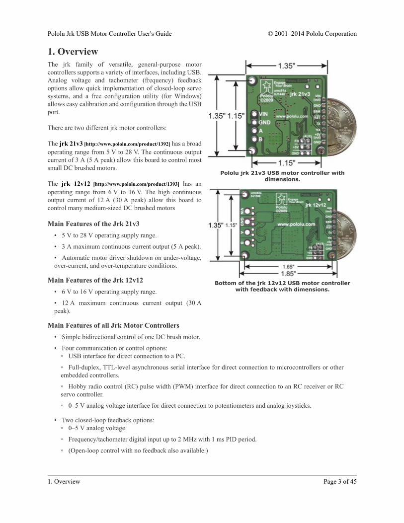
Pololu jrk 21v3 USB motor controller withdimensions.
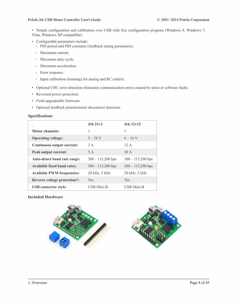
Bottom of the jrk 12v12 USB motor controllerwith feedback with dimensions.
1. OverviewThe jrk family of versatile, general-purpose motorcontrollers supports a variety of interfaces, including USB.Analog voltage and tachometer (frequency) feedbackoptions allow quick implementation of closed-loop servosystems, and a free configuration utility (for Windows)allows easy calibration and configuration through the USBport.
There are two different jrk motor controllers:
The jrk 21v3 [http://www.pololu.com/product/1392] has a broadoperating range from 5 V to 28 V. The continuous outputcurrent of 3 A (5 A peak) allow this board to control mostsmall DC brushed motors.
The jrk 12v12 [http://www.pololu.com/product/1393] has anoperating range from 6 V to 16 V. The high continuousoutput current of 12 A (30 A peak) allow this board tocontrol many medium-sized DC brushed motors
Main Features of the Jrk 21v3• 5 V to 28 V operating supply range.
• 3 A maximum continuous current output (5 A peak).
• Automatic motor driver shutdown on under-voltage,over-current, and over-temperature conditions.
Main Features of the Jrk 12v12• 6 V to 16 V operating supply range.
• 12 A maximum continuous current output (30 Apeak).
Main Features of all Jrk Motor Controllers• Simple bidirectional control of one DC brush motor.
• Four communication or control options:◦ USB interface for direct connection to a PC.
◦ Full-duplex, TTL-level asynchronous serial interface for direct connection to microcontrollers or otherembedded controllers.
◦ Hobby radio control (RC) pulse width (PWM) interface for direct connection to an RC receiver or RCservo controller.
◦ 0–5 V analog voltage interface for direct connection to potentiometers and analog joysticks.
• Two closed-loop feedback options:◦ 0–5 V analog voltage.
◦ Frequency/tachometer digital input up to 2 MHz with 1 ms PID period.
◦ (Open-loop control with no feedback also available.)
Pololu Jrk USB Motor Controller User's Guide © 2001–2014 Pololu Corporation
1. Overview Page 3 of 45
• Simple configuration and calibration over USB with free configuration program (Windows 8, Windows 7,Vista, Windows XP compatible).
• Configurable parameters include:◦ PID period and PID constants (feedback tuning parameters).
◦ Maximum current.
◦ Maximum duty cycle.
◦ Maximum acceleration.
◦ Error response.
◦ Input calibration (learning) for analog and RC control.
• Optional CRC error detection eliminates communication errors caused by noise or software faults.
• Reversed power protection.
• Field-upgradeable firmware.
• Optional feedback potentiometer disconnect detection.
Specifications
_ Jrk 21v3 Jrk 12v12
Motor channels: 1 1
Operating voltage: 5 – 28 V 6 – 16 V
Continuous output current: 3 A 12 A
Peak output current: 5 A 30 A
Auto-detect baud rate range: 300 – 115,200 bps 300 – 115,200 bps
Available fixed baud rates: 300 – 115,200 bps 300 – 115,200 bps
Available PWM frequencies: 20 kHz, 5 kHz 20 kHz, 5 kHz
Reverse voltage protection?: Yes Yes
USB connector style: USB Mini-B USB Mini-B
Included Hardware
Pololu Jrk USB Motor Controller User's Guide © 2001–2014 Pololu Corporation
1. Overview Page 4 of 45
The jrk 21v3 and jrk 12v12 each ship with a straight 0.1″ breakaway male header [http://www.pololu.com/product/965]strip and two appropriately sized 2-pin terminal blocks (3.5 mm pitch for the 21v3 and 5 mm pitch for the 12v12). Toprovide maximum flexibility, none of these parts are soldered to the board (unless you ordered our fully assembledjrk 21v3 [http://www.pololu.com/product/1394], which ships with these parts soldered in as shown in the assembled jrk21v3 picture above).
For the most compact installation, you can solder wires directly to the jrk pads themselves and skip using the includedhardware. The included hardware allows you to make less permanent connections. You can break the header strip intosmaller pieces, such as an 8×1 piece and two 3×1 pieces, and solder these strips into the jrk’s I/O pads.
The three mounting holes are intended for use with #2 screws [http://www.pololu.com/category/101/nuts-and-screws] (notincluded).
Note: A USB A to mini-B cable [http://www.pololu.com/product/130] (not included) is required to connectthis device to a computer.
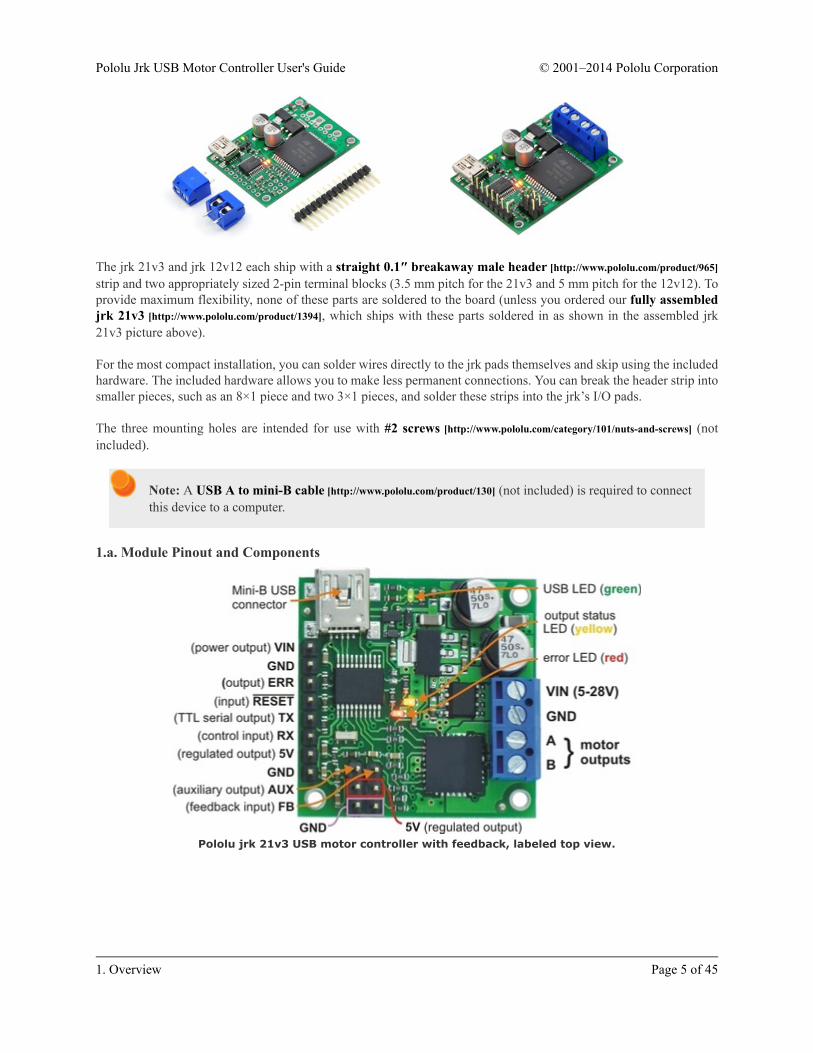
1.a. Module Pinout and Components
Pololu jrk 21v3 USB motor controller with feedback, labeled top view.
Pololu Jrk USB Motor Controller User's Guide © 2001–2014 Pololu Corporation
1. Overview Page 5 of 45
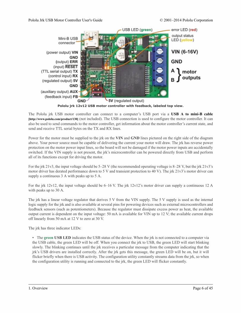
Pololu jrk 12v12 USB motor controller with feedback, labeled top view.
The Pololu jrk USB motor controller can connect to a computer’s USB port via a USB A to mini-B cable[http://www.pololu.com/product/130] (not included). The USB connection is used to configure the motor controller. It canalso be used to send commands to the motor controller, get information about the motor controller’s current state, andsend and receive TTL serial bytes on the TX and RX lines.
Power for the motor must be supplied to the jrk on the VIN and GND lines pictured on the right side of the diagramabove. Your power source must be capable of delivering the current your motor will draw. The jrk has reverse powerprotection on the motor power input lines, so the board will not be damaged if the motor power inputs are accidentallyswitched. If the VIN supply is not present, the jrk’s microcontroller can be powered directly from USB and performall of its functions except for driving the motor.
For the jrk 21v3, the input voltage should be 5–28 V (the recommended operating voltage is 8–28 V, but the jrk 21v3’smotor driver has derated performance down to 5 V and transient protection to 40 V). The jrk 21v3’s motor driver cansupply a continuous 3 A with peaks up to 5 A.
For the jrk 12v12, the input voltage should be 6–16 V. The jrk 12v12’s motor driver can supply a continuous 12 Awith peaks up to 30 A.
The jrk has a linear voltage regulator that derives 5 V from the VIN supply. The 5 V supply is used as the internallogic supply for the jrk and is also available at several pins for powering devices such as external microcontrollers andfeedback sensors (such as potentiometers). Because the regulator must dissipate excess power as heat, the availableoutput current is dependent on the input voltage: 50 mA is available for VIN up to 12 V; the available current dropsoff linearly from 50 mA at 12 V to zero at 30 V.
The jrk has three indicator LEDs:
• The green USB LED indicates the USB status of the device. When the jrk is not connected to a computer viathe USB cable, the green LED will be off. When you connect the jrk to USB, the green LED will start blinkingslowly. The blinking continues until the jrk receives a particular message from the computer indicating that thejrk’s USB drivers are installed correctly. After the jrk gets this message, the green LED will be on, but it willflicker briefly when there is USB activity. The configuration utility constantly streams data from the jrk, so whenthe configuration utility is running and connected to the jrk, the green LED will flicker constantly.
Pololu Jrk USB Motor Controller User's Guide © 2001–2014 Pololu Corporation
1. Overview Page 6 of 45
• The red error LED indicates an error. If there is an error stopping the motor (besides the Awaiting Commanderror bit), then the red LED will be on. The red LED is tied to the active-high output ERR, so when there is anerror, ERR will be driven high, and otherwise it will be pulled low through the LED.
• The yellow output status LED indicates the status of the motor. If the yellow LED is off, then an error (otherthan the Awaiting Command error bit) is stopping the motor. If the yellow LED is flashing slowly (once persecond), then either the motor is off (the Awaiting Command Error bit is set) or the jrk is in speed control modeand the duty cycle is zero. If the yellow LED is on solid, then the motor is on and the motor has reached thedesired state. For analog and pulse width feedback modes, this means that the target is within 20 of the scaledfeedback. For speed control mode, this means that the duty cycle equals the duty cycle target. If the yellow LEDis flashing quickly (16 times per second), then the motor is on and the motor has not reached its desired state.
The ERR line is an optional output that is tied to the red error LED described above. It is driven high when thered LED is on, and it is a pulled low through the red LED when the red LED is off. Since the ERR line is neverdriven low, it is safe to connect the ERR line of multiple jrks together. Please note, however, that doing this will causethe error LEDs of all connected jrks to turn on whenever one jrk experiences an error; the ERR output of the jrkexperiencing the error will drive the LEDs of any other jrks it is connected to, even though they are not experiencingerror conditions themselves. For more information on the possible error conditions and response options, please seeSection 3.f.
The TX line transmits non-inverted, TTL (0 – 5 V) serial bytes. These bytes can either be responses to serialcommands sent to the jrk, or arbitrary bytes sent from the computer via the USB connection. For more informationabout the jrk’s serial interface, see Section 4.
The RX line is the jrk’s control input. In serial input mode, the RX line is used to receive non-inverted, TTL (0 –5 V) serial bytes. These bytes can either be serial commands for the jrk, arbitrary bytes to send back to the computervia the USB connection, or both. For more information about the jrk’s serial interface, see Section 4. In analog inputmode, RX is the analog input line used to determine the system’s target output. In pulse width input mode, the jrkmeasures the duration of pulses on the RX line to determine the system’s target output. Please see Section 3.b formore information on control input signals.
The FB line is the jrk’s feedback input. In analog feedback mode, the voltage on the FB line is used as a measurementof the output of the system. In frequency feedback mode, the frequency of low-to-high transitions on the FB line isused as a measurement of the output of the system. Please see Section 3.c for more information on feedback signals.
The AUX line is an output that is generally high whenever the jrk has power. The line will only go low for tworeasons:
1. If the jrk’s microcontroller goes to sleep (because there is no VIN supply and the device has entered USBsuspend mode), the pin is tri-stated and pulled low through a resistor.
2. If the Detect disconnect with AUX option is enabled for either the feedback or the input, then the jrk willdrive AUX low for about 150 μs each PID period to check if the feedback and/or analog inputs are disconnected.
The RST pin can be driven low to perform a hard reset of the jrk’s microcontroller, but this should generally not benecessary for typical applications. The line is internally pulled high, so it is safe to leave this pin unconnected.
1.b. Supported Operating SystemsThe jrk works under Microsoft Windows 8, Windows 7, Windows Vista, Windows XP, Linux, and Max OS X 10.7 orlater.
The configuration utility works only in Windows, so the jrk must be initially configured from a Windows computer,but after that it can be controlled from a Linux or Mac computer.
Pololu Jrk USB Motor Controller User's Guide © 2001–2014 Pololu Corporation
1. Overview Page 7 of 45
Under Linux, the two virtual COM ports created by the jrk should appear as devices with names like /dev/ttyACM0and /dev/ttyACM1 (the number depends on how many other ACM devices you have plugged in) and you can use anyterminal program (such as screen) to send and receive bytes on those ports. Alternatively, you can use the Pololu USBSoftware Development Kit which supports Linux and has example applications that control the jrk using its nativeUSB interface (see Section 6).
Under Mac OS X 10.7 or later, the two virtual COM ports created by the jrk should appear as devices with nameslike /dev/cu.usbmodem00034567 and you can use any terminal program (such as screen) to send and receive bytes onthose ports.
Mac OS X compatibility: we have confirmed that the jrk works on Mac OS X 10.7 and we can assistwith advanced technical issues, but most of our tech support staff does not use Macs, so basic supportfor Mac OS X is limited.
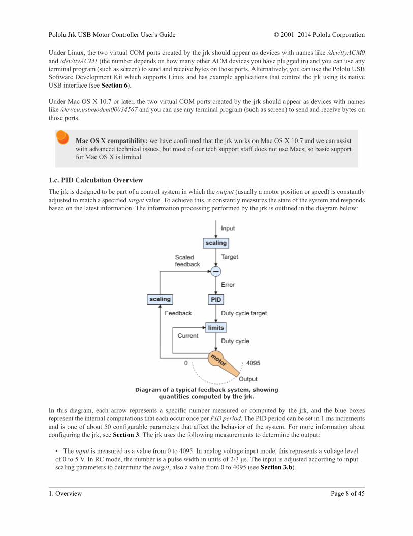
1.c. PID Calculation OverviewThe jrk is designed to be part of a control system in which the output (usually a motor position or speed) is constantlyadjusted to match a specified target value. To achieve this, it constantly measures the state of the system and respondsbased on the latest information. The information processing performed by the jrk is outlined in the diagram below:
Diagram of a typical feedback system, showingquantities computed by the jrk.
In this diagram, each arrow represents a specific number measured or computed by the jrk, and the blue boxesrepresent the internal computations that each occur once per PID period. The PID period can be set in 1 ms incrementsand is one of about 50 configurable parameters that affect the behavior of the system. For more information aboutconfiguring the jrk, see Section 3. The jrk uses the following measurements to determine the output:
• The input is measured as a value from 0 to 4095. In analog voltage input mode, this represents a voltage levelof 0 to 5 V. In RC mode, the number is a pulse width in units of 2/3 μs. The input is adjusted according to inputscaling parameters to determine the target, also a value from 0 to 4095 (see Section 3.b).
Pololu Jrk USB Motor Controller User's Guide © 2001–2014 Pololu Corporation
1. Overview Page 8 of 45
• The feedback is measured as a value from 0 to 4095. In analog voltage feedback mode, this represents avoltage level of 0 to 5 V. In digital frequency mode, it is a representation of the output speed (see Section 3.c.)The jrk uses this value to compute the scaled feedback, which is a representation of the output of the entirecontrol system. A scaled feedback of 0 should represent the minimum position of the system, and 4095 shouldrepresent the maximum position.
• The current through the motor is measured as a number from 0 to 255. A calibration value relates this to anactual current in amps.
Every PID cycle, the jrk performs the following computations to determine the behavior of the motor (see Section3.d for more information):
1. The error is computed as the difference of scaled feedback and target (error = scaled feedback − target).
2. An implementation of the PID algorithm is applied to the error. PID stands for the three terms that are addedtogether: proportional (proportional to the error), integral (proportional to the accumulated sum of the error overtime), and derivative (proportional to the difference of the error relative to the previous PID period.) The threeconstants of proportionality are the most important parameters determining the behavior of the control system.The result of the PID algorithm is a number from -600 to +600 called the duty cycle target.
3. The duty cycle target is reduced according to various configurable limits, including acceleration, current, andmaximum duty cycle limits (Section 3.e). The limits are intended to prevent the system from causing damage toitself under most circumstances.
The resulting value becomes the duty cycle of the PWM (pulse width modulation) signal applied to the motor. A valueof +600 corresponds to 100% duty cycle in the forward direction, a value of -600 corresponds to 100% duty cycle inthe reverse direction, and a value of 0 corresponds to 0% duty cycle or off.
Various parameters and commands have an effect on the steps described above. For example, feedback may be turnedoff so that the jrk can become a simple speed controller; in this case the PID calculation is bypassed and the dutycycle target is just equal to the target minus 2048. In this mode, limits applied to the duty cycle continue to provide auseful way of preventing damage to the system. As another example, a command to turn the system off prevents themotors from being driven, but all measurements and calculations continue to occur normally.
Pololu Jrk USB Motor Controller User's Guide © 2001–2014 Pololu Corporation
1. Overview Page 9 of 45
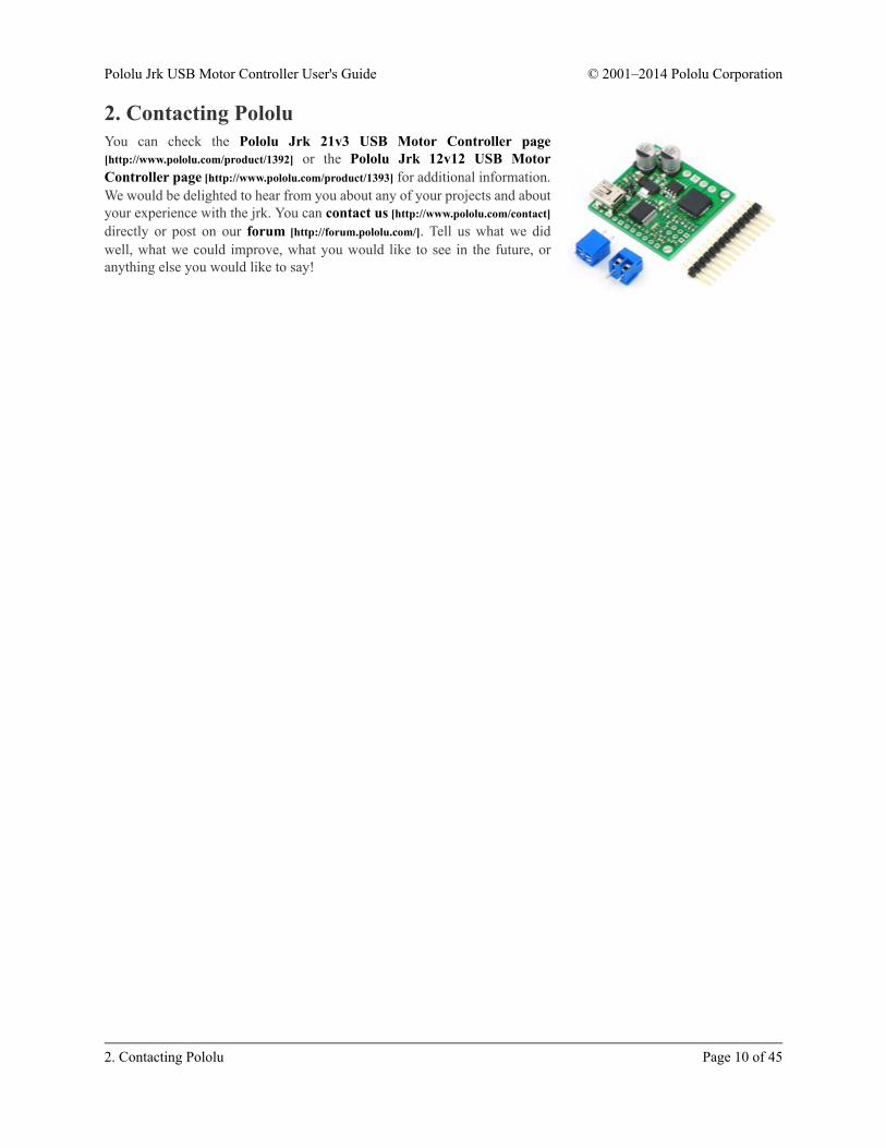
2. Contacting PololuYou can check the Pololu Jrk 21v3 USB Motor Controller page[http://www.pololu.com/product/1392] or the Pololu Jrk 12v12 USB MotorController page [http://www.pololu.com/product/1393] for additional information.We would be delighted to hear from you about any of your projects and aboutyour experience with the jrk. You can contact us [http://www.pololu.com/contact]directly or post on our forum [http://forum.pololu.com/]. Tell us what we didwell, what we could improve, what you would like to see in the future, oranything else you would like to say!
Pololu Jrk USB Motor Controller User's Guide © 2001–2014 Pololu Corporation
2. Contacting Pololu Page 10 of 45
3. Configuring the Motor Controller3.a. Installing Windows Drivers and the Configuration Utility
If you use Windows XP, you will need to have Service Pack 3 [http://www.microsoft.com/downloads/details.aspx?FamilyId=68C48DAD-BC34-40BE-8D85-6BB4F56F5110] installed before installing the drivers forthe jrk. See below for details.
Before you connect your Pololu jrk USB motor controller to a computer running Microsoft Windows, you must installits drivers:
1. Download the jrk drivers and configuration software [http://www.pololu.com/file/download/jrk-windows-121204.zip?file_id=0J221] (5MB zip)
2. Open the ZIP archive and run setup.exe. If the installer fails, you may have to extract all the files to atemporary directory, right click setup.exe, and select “Run as administrator”. The installer will guide you throughthe steps required to install the Pololu Jrk Configuration Utility, the jrk command-line utility (JrkCmd), and thejrk drivers on your computer.
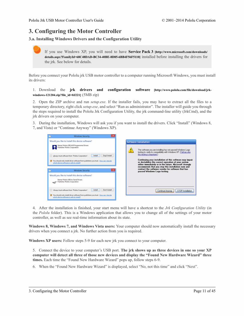
3. During the installation, Windows will ask you if you want to install the drivers. Click “Install” (Windows 8,7, and Vista) or “Continue Anyway” (Windows XP).
4. After the installation is finished, your start menu will have a shortcut to the Jrk Configuration Utility (inthe Pololu folder). This is a Windows application that allows you to change all of the settings of your motorcontroller, as well as see real-time information about its state.
Windows 8, Windows 7, and Windows Vista users: Your computer should now automatically install the necessarydrivers when you connect a jrk. No further action from you is required.
Windows XP users: Follow steps 5-9 for each new jrk you connect to your computer.
5. Connect the device to your computer’s USB port. The jrk shows up as three devices in one so your XPcomputer will detect all three of those new devices and display the “Found New Hardware Wizard” threetimes. Each time the “Found New Hardware Wizard” pops up, follow steps 6-9.
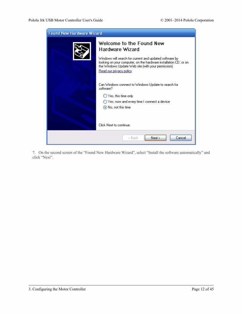
6. When the “Found New Hardware Wizard” is displayed, select “No, not this time” and click “Next”.
Pololu Jrk USB Motor Controller User's Guide © 2001–2014 Pololu Corporation
3. Configuring the Motor Controller Page 11 of 45
7. On the second screen of the “Found New Hardware Wizard”, select “Install the software automatically” andclick “Next”.
Pololu Jrk USB Motor Controller User's Guide © 2001–2014 Pololu Corporation
3. Configuring the Motor Controller Page 12 of 45
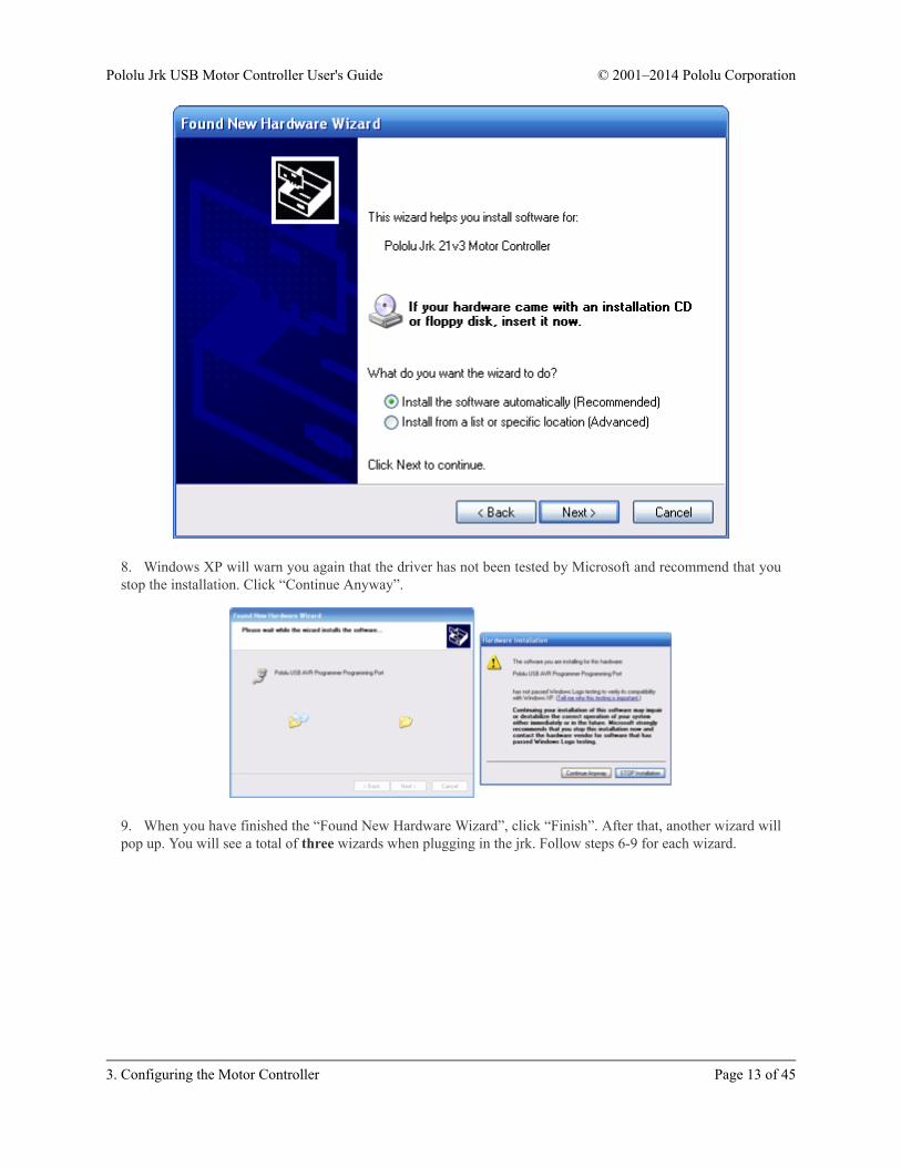
8. Windows XP will warn you again that the driver has not been tested by Microsoft and recommend that youstop the installation. Click “Continue Anyway”.
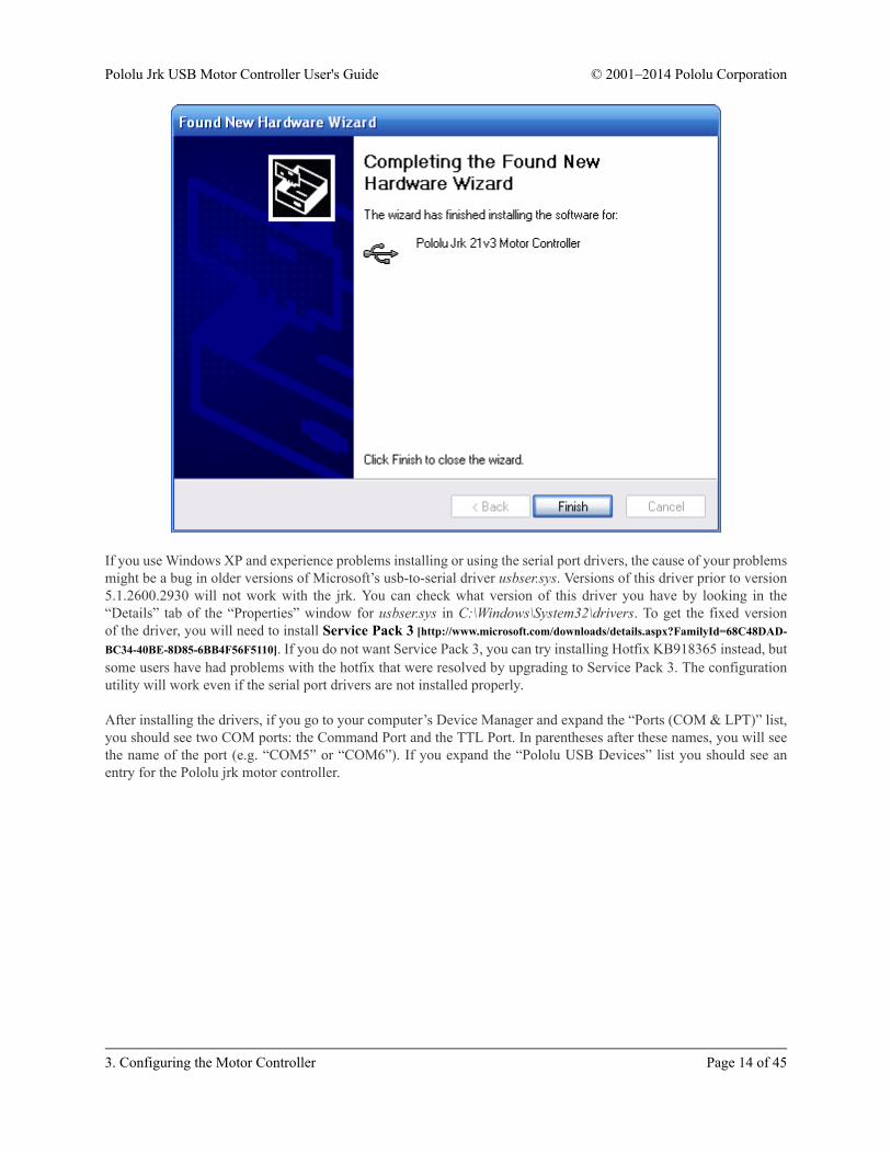
9. When you have finished the “Found New Hardware Wizard”, click “Finish”. After that, another wizard willpop up. You will see a total of three wizards when plugging in the jrk. Follow steps 6-9 for each wizard.
Pololu Jrk USB Motor Controller User's Guide © 2001–2014 Pololu Corporation
3. Configuring the Motor Controller Page 13 of 45
If you use Windows XP and experience problems installing or using the serial port drivers, the cause of your problemsmight be a bug in older versions of Microsoft’s usb-to-serial driver usbser.sys. Versions of this driver prior to version5.1.2600.2930 will not work with the jrk. You can check what version of this driver you have by looking in the“Details” tab of the “Properties” window for usbser.sys in C:\Windows\System32\drivers. To get the fixed versionof the driver, you will need to install Service Pack 3 [http://www.microsoft.com/downloads/details.aspx?FamilyId=68C48DAD-BC34-40BE-8D85-6BB4F56F5110]. If you do not want Service Pack 3, you can try installing Hotfix KB918365 instead, butsome users have had problems with the hotfix that were resolved by upgrading to Service Pack 3. The configurationutility will work even if the serial port drivers are not installed properly.
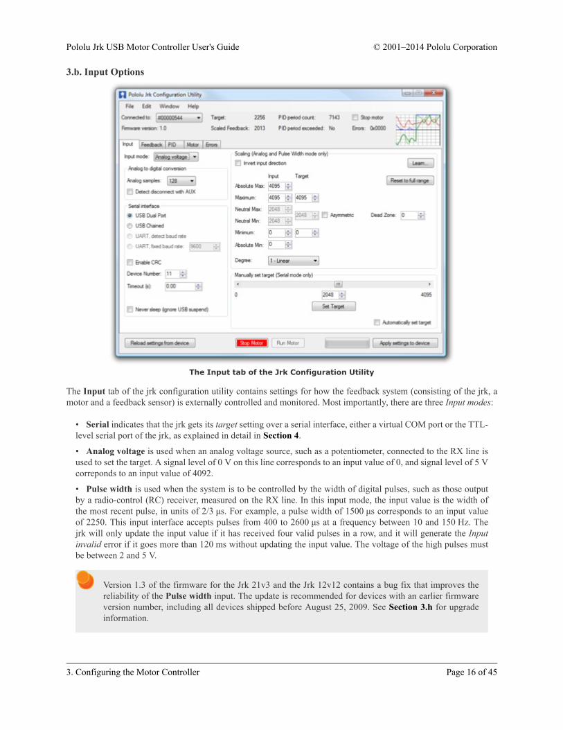
After installing the drivers, if you go to your computer’s Device Manager and expand the “Ports (COM & LPT)” list,you should see two COM ports: the Command Port and the TTL Port. In parentheses after these names, you will seethe name of the port (e.g. “COM5” or “COM6”). If you expand the “Pololu USB Devices” list you should see anentry for the Pololu jrk motor controller.
Pololu Jrk USB Motor Controller User's Guide © 2001–2014 Pololu Corporation
3. Configuring the Motor Controller Page 14 of 45
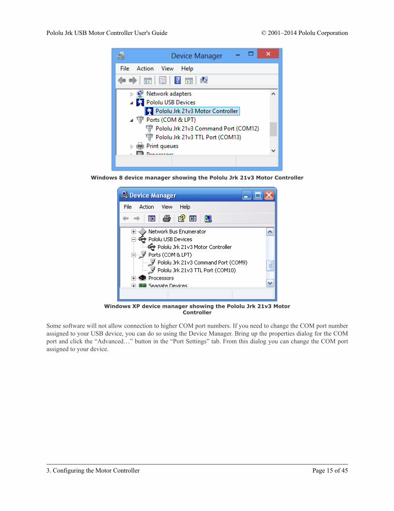
Windows 8 device manager showing the Pololu Jrk 21v3 Motor Controller
Windows XP device manager showing the Pololu Jrk 21v3 MotorController
Some software will not allow connection to higher COM port numbers. If you need to change the COM port numberassigned to your USB device, you can do so using the Device Manager. Bring up the properties dialog for the COMport and click the “Advanced…” button in the “Port Settings” tab. From this dialog you can change the COM portassigned to your device.
Pololu Jrk USB Motor Controller User's Guide © 2001–2014 Pololu Corporation
3. Configuring the Motor Controller Page 15 of 45
3.b. Input Options
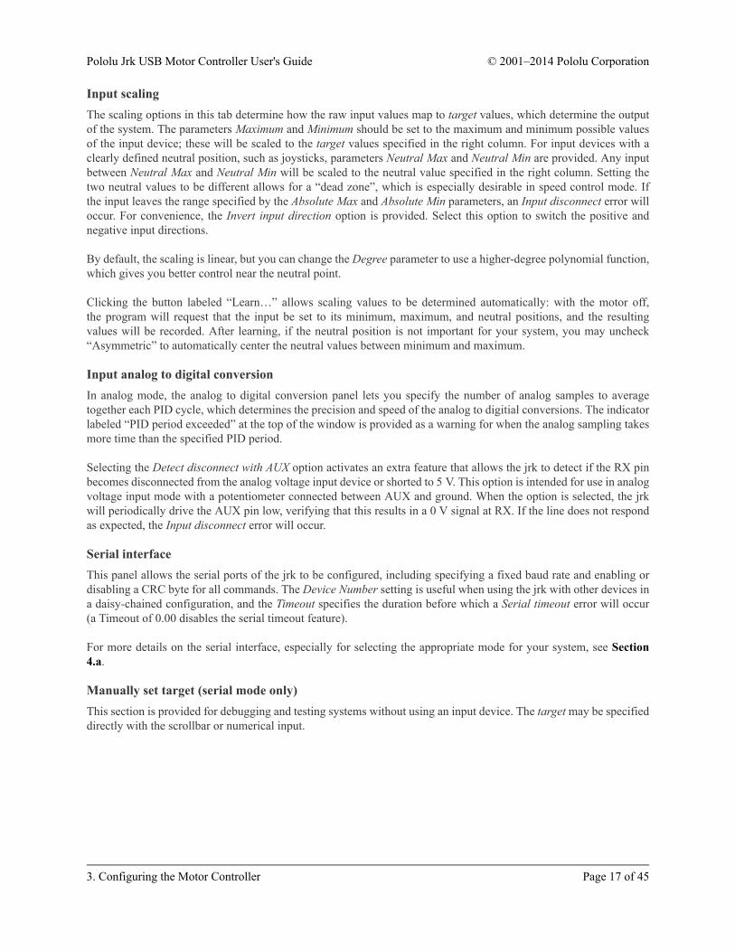
The Input tab of the Jrk Configuration Utility
The Input tab of the jrk configuration utility contains settings for how the feedback system (consisting of the jrk, amotor and a feedback sensor) is externally controlled and monitored. Most importantly, there are three Input modes:
• Serial indicates that the jrk gets its target setting over a serial interface, either a virtual COM port or the TTL-level serial port of the jrk, as explained in detail in Section 4.
• Analog voltage is used when an analog voltage source, such as a potentiometer, connected to the RX line isused to set the target. A signal level of 0 V on this line corresponds to an input value of 0, and signal level of 5 Vcorreponds to an input value of 4092.
• Pulse width is used when the system is to be controlled by the width of digital pulses, such as those outputby a radio-control (RC) receiver, measured on the RX line. In this input mode, the input value is the width ofthe most recent pulse, in units of 2/3 μs. For example, a pulse width of 1500 μs corresponds to an input valueof 2250. This input interface accepts pulses from 400 to 2600 μs at a frequency between 10 and 150 Hz. Thejrk will only update the input value if it has received four valid pulses in a row, and it will generate the Inputinvalid error if it goes more than 120 ms without updating the input value. The voltage of the high pulses mustbe between 2 and 5 V.
Version 1.3 of the firmware for the Jrk 21v3 and the Jrk 12v12 contains a bug fix that improves thereliability of the Pulse width input. The update is recommended for devices with an earlier firmwareversion number, including all devices shipped before August 25, 2009. See Section 3.h for upgradeinformation.
Pololu Jrk USB Motor Controller User's Guide © 2001–2014 Pololu Corporation
3. Configuring the Motor Controller Page 16 of 45
Input scalingThe scaling options in this tab determine how the raw input values map to target values, which determine the outputof the system. The parameters Maximum and Minimum should be set to the maximum and minimum possible valuesof the input device; these will be scaled to the target values specified in the right column. For input devices with aclearly defined neutral position, such as joysticks, parameters Neutral Max and Neutral Min are provided. Any inputbetween Neutral Max and Neutral Min will be scaled to the neutral value specified in the right column. Setting thetwo neutral values to be different allows for a “dead zone”, which is especially desirable in speed control mode. Ifthe input leaves the range specified by the Absolute Max and Absolute Min parameters, an Input disconnect error willoccur. For convenience, the Invert input direction option is provided. Select this option to switch the positive andnegative input directions.
By default, the scaling is linear, but you can change the Degree parameter to use a higher-degree polynomial function,which gives you better control near the neutral point.
Clicking the button labeled “Learn…” allows scaling values to be determined automatically: with the motor off,the program will request that the input be set to its minimum, maximum, and neutral positions, and the resultingvalues will be recorded. After learning, if the neutral position is not important for your system, you may uncheck“Asymmetric” to automatically center the neutral values between minimum and maximum.
Input analog to digital conversionIn analog mode, the analog to digital conversion panel lets you specify the number of analog samples to averagetogether each PID cycle, which determines the precision and speed of the analog to digitial conversions. The indicatorlabeled “PID period exceeded” at the top of the window is provided as a warning for when the analog sampling takesmore time than the specified PID period.
Selecting the Detect disconnect with AUX option activates an extra feature that allows the jrk to detect if the RX pinbecomes disconnected from the analog voltage input device or shorted to 5 V. This option is intended for use in analogvoltage input mode with a potentiometer connected between AUX and ground. When the option is selected, the jrkwill periodically drive the AUX pin low, verifying that this results in a 0 V signal at RX. If the line does not respondas expected, the Input disconnect error will occur.
Serial interfaceThis panel allows the serial ports of the jrk to be configured, including specifying a fixed baud rate and enabling ordisabling a CRC byte for all commands. The Device Number setting is useful when using the jrk with other devices ina daisy-chained configuration, and the Timeout specifies the duration before which a Serial timeout error will occur(a Timeout of 0.00 disables the serial timeout feature).
For more details on the serial interface, especially for selecting the appropriate mode for your system, see Section4.a.
Manually set target (serial mode only)This section is provided for debugging and testing systems without using an input device. The target may be specifieddirectly with the scrollbar or numerical input.
Pololu Jrk USB Motor Controller User's Guide © 2001–2014 Pololu Corporation
3. Configuring the Motor Controller Page 17 of 45
3.c. Feedback Options
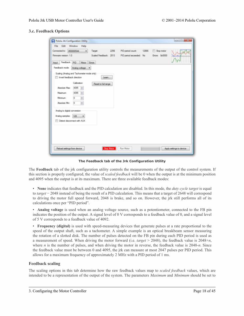
The Feedback tab of the Jrk Configuration Utility
The Feedback tab of the jrk configuration utility controls the measurements of the output of the control system. Ifthis section is properly configured, the value of scaled feedback will be 0 when the output is at the minimum positionand 4095 when the output is at its maximum. There are three available feedback modes:
• None indicates that feedback and the PID calculation are disabled. In this mode, the duty cycle target is equalto target − 2048 instead of being the result of a PID calculation. This means that a target of 2648 will correspondto driving the motor full speed forward, 2048 is brake, and so on. However, the jrk still performs all of itscalculations once per “PID period”.
• Analog voltage is used when an analog voltage source, such as a potentiometer, connected to the FB pinindicates the position of the output. A signal level of 0 V corresponds to a feedback value of 0, and a signal levelof 5 V corresponds to a feedback value of 4092.
• Frequency (digital) is used with speed-measuring devices that generate pulses at a rate proportional to thespeed of the output shaft, such as a tachometer. A simple example is an optical breakbeam sensor measuringthe rotation of a slotted disk. The number of pulses detected on the FB pin during each PID period is used asa measurement of speed. When driving the motor forward (i.e. target > 2048), the feedback value is 2048+n,where n is the number of pulses, and when driving the motor in reverse, the feedback value is 2048-n. Sincethe feedback value must be between 0 and 4095, the jrk can measure at most 2047 pulses per PID period. Thisallows for a maximum frequency of approximately 2 MHz with a PID period of 1 ms.
Feedback scalingThe scaling options in this tab determine how the raw feedback values map to scaled feedback values, which areintended to be a representation of the output of the system. The parameters Maximum and Minimum should be set to
Pololu Jrk USB Motor Controller User's Guide © 2001–2014 Pololu Corporation
3. Configuring the Motor Controller Page 18 of 45

the maximum and minimum possible values of the output; these will be converted to scaled feedback values of 4095and 0, respectively. If the feedback leaves the range specified by the Absolute Max and Absolute Min parameters, aFeedback disconnect error will occur. For convenience, the Invert feedback direction option is provided. Select thisoption if the direction of motion that you would like to call positive actually results in a decreasing feedback value.
Clicking the button labeled “Learn…” allows scaling values to be determined automatically: with the motor off,the program will request that the output be moved to its minimum and maximum, and the resulting values will berecorded.
Input analog to digital conversionIn analog mode, the analog to digital conversion panel lets you specify the number of analog samples to averagetogether each PID cycle, which determines the precision and speed of the analog to digital conversions. The indicatorlabeled “PID period exceeded” at the top of the window is provided as a warning for when the analog sampling takesmore time than the specified PID period.
Selecting the Detect disconnect with AUX option activates an extra feature that allows the jrk to detect if the FB pinbecomes disconnected from the analog voltage input device or shorted to 5 V. This option is intended for use in analogvoltage feedback mode with a potentiometer connected between AUX and ground. When the option is selected, thejrk will periodically drive the AUX pin low, verifying that this results in a 0 V signal at FB. If the line does notrespond as expected the Feedback disconnect error will occur.
3.d. PID Options
The PID tab of the Jrk Configuration Utility
The PID tab of the jrk configuration utility controls the central calculation performed by the jrk:
Pololu Jrk USB Motor Controller User's Guide © 2001–2014 Pololu Corporation
3. Configuring the Motor Controller Page 19 of 45
duty cycle target =(Proportional coefficient) × error+ (Integral coefficient) × integral+ (Derivative coefficient) × derivative
The integral is computed as the sum of the error over all PID cycles, and the derivative is the current error minusthe previous error. The error itself is the difference of the scaled feedback and the target (error = scaled feedback– target). Each of the PID coefficients is specified as an integer value divided by a power of two. The proportionaland derivative coefficients can have values from 0.00003 to 1024, and any value above 0.0152 can be approximatedwithin 0.5%. To get the closest approximation to a desired value, type the number into the box after the equal sign,and the best possible numerator and denominator will be computed. In the case of the integral coefficient, the rangeof the denominator is actually 23 to 218; this is a more useful range, since the integral is usually much larger than theerror or derivative.
The PID period can be adjusted here; this sets the rate at which the jrk runs through all of its calculations. Note that ahigher PID period will result in a more slowly changing integral and a higher derivative, so that the two correspondingPID constants might need to be adjusted whenever the PID period is changed.
Preventing integral wind-upThree options are provided for limiting “integral wind-up”, which is the uncontrolled growth of the integral whenthe feedback system is temporarily unable to keep the error small. This might happen, for example, when the targetis changing quickly. One option is the integral limit, a value from 0 to 32767 that simply limits the magnitude ofthe integral. Note that the maximum value of the integral term can be computed as the integral coefficient times theintegral limit: if this is very small compared to 600 (maximum duty cycle), the integral term will have at most a verysmall effect on the duty cycle.
Another option causes the integral to reset to 0 when the proportional term exceeds the maximum duty cycleparameter. For example, if this option is selected when the proportional coefficient is 15 and the maximum duty cycleis 300, the integral will reset whenever the error is larger than 20.
Additionally the Feedback dead zone option sets the duty cycle target to zero and resets the integral whenever themagnitude of the error is smaller than this amount. This is useful for preventing the motor from driving when thetarget is very close to scaled feedback. The feedback dead zone uses hysteresis to keep the system from simply ridingthe edge of the dead zone; once in the dead zone, the duty cycle and integral will remain zero until the magnitude ofthe error exceeds twice this value.
Pololu Jrk USB Motor Controller User's Guide © 2001–2014 Pololu Corporation
3. Configuring the Motor Controller Page 20 of 45
3.e. Motor Options
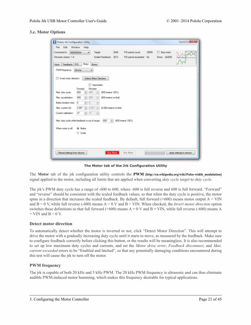
The Motor tab of the Jrk Configuration Utility
The Motor tab of the jrk configuration utility controls the PWM [http://en.wikipedia.org/wiki/Pulse-width_modulation]signal applied to the motor, including all limits that are applied when converting duty cycle target to duty cycle.
The jrk’s PWM duty cycle has a range of -600 to 600, where -600 is full reverse and 600 is full forward. “Forward”and “reverse” should be consistent with the scaled feedback values, so that when the duty cycle is positive, the motorspins in a direction that increases the scaled feedback. By default, full forward (+600) means motor output A = VINand B = 0 V, while full reverse (-600) means A = 0 V and B = VIN. When checked, the Invert motor direction optionswitches these definitions so that full forward (+600) means A = 0 V and B = VIN, while full reverse (-600) means A= VIN and B = 0 V.
Detect motor directionTo automatically detect whether the motor is inverted or not, click “Detect Motor Direction”. This will attempt todrive the motor with a gradually increasing duty cycle until it starts to move, as measured by the feedback. Make sureto configure feedback correctly before clicking this button, or the results will be meaningless. It is also recommendedto set up low maximum duty cycles and currents, and set the Motor drive error, Feedback disconnect, and Max.current exceeded errors to be “Enabled and latched”, so that any potentially damaging conditions encountered duringthis test will cause the jrk to turn off the motor.
PWM frequencyThe jrk is capable of both 20 kHz and 5 kHz PWM. The 20 kHz PWM frequency is ultrasonic and can thus eliminateaudible PWM-induced motor humming, which makes this frequency desirable for typical applications.
Pololu Jrk USB Motor Controller User's Guide © 2001–2014 Pololu Corporation
3. Configuring the Motor Controller Page 21 of 45
However, a higher PWM frequency means greater power loss due to switching, which could make a 5 kHz PWMfrequency a better choice for certain applications.
Additionally, the 5 kHz PWM frequency allows for finer control at duty cycles approaching 0% or 100% (±600). Thisis because the timing characteristics of the jrk motor drivers make it so that very short PWM pulses (either low orhigh) have no effect on the output voltage. This limitation is more pronounced on the jrk 21v3, in which pulses thatare shorter than approximately 4 μs have no effect on the output voltage. Therefore, at 20 kHz, the jrk 21v3 with aduty cycle less than 8% will effectively have a duty cycle of 0% (braking), while a duty cycle greater than 92% willbe the same as a duty cycle of 100% (the jrk 12v12 can typically go a bit closer to 0% and 100%). At 5 kHz, the effectis smaller by a factor of four: a duty cycle less than 2% will be the same as a duty cycle of 0% (braking) while a dutycycle greater than 98% will be the same as a duty cycle of 100%.
LimitsVarious limits may be applied to the duty cycle, each of which can be configured separately for forward (positive dutycycle) and reverse (negative duty cycle) if the “Asymmetric” option is checked:
Max. duty cycle limits the duty cycle itself.
Max. acceleration limits the amount that the duty cycle can change by in a single PID period. For example, if thereis an acceleration limit of 10 in both directions, and the current duty cycle is 300, then the duty cycle in the next PIDperiod is limited to be within -10 to 310.
Max. current causes the jrk to measure the motor driver current and adjust the duty cycle as necessary to limit it thespecified value. The current is reported as a number from 0 to 255 that is multiplied by the Current calibration to geta number in mA, so increasing the current calibration value will increase the measured value. For accurate currentlimiting, acceleration should be limited; otherwise the duty cycle will tend to oscillate when the maximum current isexceeded.
Brake duration is a feature that is most useful for large motors with high-inertia loads used with frequency feedbackor speed control mode (no feedback). If this option is used, the jrk will automatically keep the motor at a duty cycleof 0 for the specified time before switching directions. The “forward” setting refers to switching from forward toreverse, and the “reverse” setting refers to switching from reverse to forward.
Max. duty cycle while feedback is out of range is an option to limit possible damage to systems by reducing themaximum duty cycle whenever the feedback value is beyond the absolute minimum and maximum values. This canbe used, for example, to slowly bring a system back into its valid range of operation when it is dangerously near alimit. The Feedback disconnect error should be disabled when this option is used.
When motor is offWhen the motor is off because of an error condition or an explicit Motor Off command, there are two options for thestate of the motor driver: brake (A and B both connected to GND) and coast (A and B floating).
You can familiarize yourself with motor coasting and braking using nothing more than a motor. First, with your motordisconnected from anything, try rotating the output shaft and note how easily it turns. Then hold the two motor leadstogether and try rotating the output shaft again. You should notice significantly more turning resistance while theleads are shorted together.
The jrk 21v3 PWMs the motor outputs between driving and braking, and a duty cycle of zero is the same as braking.
The jrk 12v12 PWMs the motor outputs between driving and coasting when the duty cycle is non-zero.
Pololu Jrk USB Motor Controller User's Guide © 2001–2014 Pololu Corporation
3. Configuring the Motor Controller Page 22 of 45
As of firmware version 1.4, the behavior of the jrk 12v12 when the duty cycle is zero depends on the“When motor is off” configuration option. In previous versions, at a duty cycle of 0, the jrk 12v12 wouldbrake the motor in one direction but let it coast in the other direction.
3.f. Error Response Options
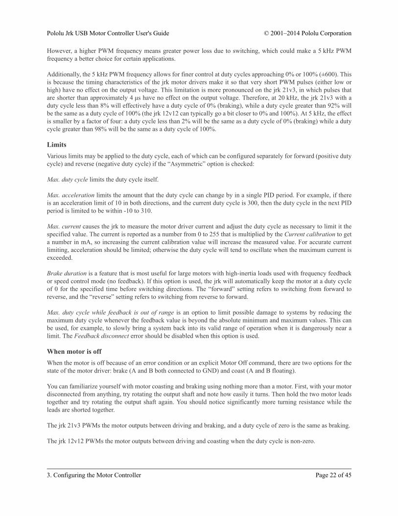
The Errors tab of the Jrk Configuration Utility
There are several errors that can stop the jrk from driving its motor. For information about what each error means, seeSection 4.f.
The jrk’s response to the different errors can be configured. Each error has up to three different available settings.
• Disabled: The jrk will ignore this error. You can still determine whether the error is occurring by checking the“Occurrence count” column in the configuration utility, or by using the Get Error Flags Occurred serial command(Section 4.f).
• Enabled: When this error happens, the jrk will turn the motor off. When the error stops happening, the motorcan restart.
• Enabled and Latched: When this error happens, the jrk will turn the motor off and set the AwaitingCommand error bit. The jrk will not drive the motor again until it receives one of the serial set target commands.The motor can also be restarted from the configuration utility.
Pololu Jrk USB Motor Controller User's Guide © 2001–2014 Pololu Corporation
3. Configuring the Motor Controller Page 23 of 45
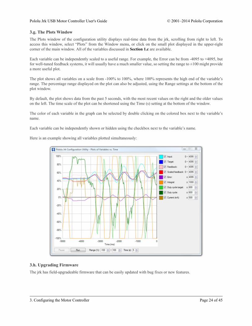
3.g. The Plots WindowThe Plots window of the configuration utility displays real-time data from the jrk, scrolling from right to left. Toaccess this window, select “Plots” from the Window menu, or click on the small plot displayed in the upper-rightcorner of the main window. All of the variables discussed in Section 1.c are available.
Each variable can be independently scaled to a useful range. For example, the Error can be from -4095 to +4095, butfor well-tuned feedback systems, it will usually have a much smaller value, so setting the range to ±100 might providea more useful plot.
The plot shows all variables on a scale from -100% to 100%, where 100% represents the high end of the variable’srange. The percentage range displayed on the plot can also be adjusted, using the Range settings at the bottom of theplot window.
By default, the plot shows data from the past 5 seconds, with the most recent values on the right and the older valueson the left. The time scale of the plot can be shortened using the Time (s) setting at the bottom of the window.
The color of each variable in the graph can be selected by double clicking on the colored box next to the variable’sname.
Each variable can be independently shown or hidden using the checkbox next to the variable’s name.
Here is an example showing all variables plotted simultaneously:
3.h. Upgrading FirmwareThe jrk has field-upgradeable firmware that can be easily updated with bug fixes or new features.
Pololu Jrk USB Motor Controller User's Guide © 2001–2014 Pololu Corporation
3. Configuring the Motor Controller Page 24 of 45
You can determine the version of your jrk’s firmware by running the configuration utility (Section 3.a), connecting toa jrk, and looking at the firmware version number which is displayed in the upper left corner below the “Connectedto” dropdown box.
Version 1.4 of the firmware for the jrk 12v12 extends the “When motor is off” parameter so that it nowaffects the behavior of the jrk whenever the duty cycle is 0. Previously, at a duty cycle of 0, the jrk 12v12would brake the motor in one direction but let it coast in the other direction. Now the default behavior isto brake in both directions, but you can configure it to coast instead. Firmware version 1.4 also makes thejrk 12v12 brake low (connect both A and B to GND) instead of braking high. All jrk 12v12s manufacturedafter August 24, 2012 ship with firmware version 1.4.
The latest version of the jrk 21v3 firmware available is Version 1.3. Do not attempt to load jrk 12v12firmware onto a jrk 21v3, or vice-versa.
To upgrade your jrk’s firmware, follow these steps:
1. Save the settings stored on your jrk using the “Save settings file…” option in the File menu. All of yoursettings will be reset to default values during the firmware upgrade.
2. Download the latest version of the firmware for your motor controller here:◦ Firmware version 1.3 for the jrk 21v3 (umc01a) [http://www.pololu.com/file/download/umc01a_v1.3.pgm?file_id=0J223] (35k pgm) — released 2009-08-25.
◦ Firmware version 1.4 for the jrk 12v12 (umc02a) [http://www.pololu.com/file/download/umc02a_v1.4.pgm?file_id=0J573] (34k pgm) — released 2012-08-15.
3. Connect your jrk to a computer running Windows using a USB cable.
4. Run the Pololu Jrk Configuration Utility. If there is only one jrk connected to your computer, theconfiguration utility will automatically connect to it. If there are multiple jrks connected to your computer, youwill have to use the “Connected to” dropdown box to select which jrk you want to connect to.
5. In the File menu, select “Upgrade Firmware…”. You will see a message asking you if you are sure you wantto proceed: click Yes. The jrk will now disconnect itself from your computer and reappear as a new device called“Pololu umc01a Bootloader” or “Pololu umc02a Bootloader”.
◦ Windows 8, Windows 7, and Vista: the driver for the bootloader will automatically be installed.
◦ Windows XP: follow steps 6-8 from Section 3.a to get the driver working.
6. Once the bootloader’s drivers are properly installed, the green LED should be blinking in a double heart-beatpattern, and there should be an entry for the bootloader in the “Ports (COM & LPT)” list of your computer’sDevice Manager.
7. Go to the window titled “Firmware Upgrade” that the Jrk Configuration Utility opened. Click the“Browse…” button and select the firmware file you downloaded.
8. Select the COM port corresponding to the bootloader. If you don’t know which COM port to select, go to theDevice Manager and look in the “Ports (COM & LPT)” section.
9. Click the “Program” button. You will see a message warning you that your jrk’s firmware is about to beerased and asking you if you are sure you want to proceed: click Yes.
Pololu Jrk USB Motor Controller User's Guide © 2001–2014 Pololu Corporation
3. Configuring the Motor Controller Page 25 of 45

10. It will take a few seconds to erase the jrk’s existing firmware and load the new firmware. Do not disconnectthe jrk during the upgrade.
11. Once the upgrade is complete, the Firmware Upgrade window will close, the jrk will disconnect from yourcomputer once again, and it will reappear as it was before. If there is only one Jrk plugged in to your computer,the Pololu Jrk Configuration Utility will connect to it. Check the firmware version number and make sure that itnow indicates the latest version of the firmware.
If you run into problems during a firmware upgrade, please contact us [http://www.pololu.com/contact] for assistance.
Pololu Jrk USB Motor Controller User's Guide © 2001–2014 Pololu Corporation
3. Configuring the Motor Controller Page 26 of 45
4. Using the Serial Interface4.a. Serial ModesThe jrk has three different serial interfaces. First, it has the RX and TX lines. The jrk can send bytes on the TX line.If the jrk is in serial input mode, the RX line can be used to receive non-inverted, TTL (0 – 5 V) serial bytes (Section4.b). If the jrk is not in serial input mode, it can not receive bytes on RX because the line is used for analog voltage orpulse width measurement. Secondly, the jrk shows up as two virtual serial ports on a computer if it is connected viaUSB. One of these ports is called the Command Port and the other is called the TTL port. You can determine theCOM port numbers of these ports by looking in your computer’s Device Manager. See Section 3.a for information.
The jrk can be configured to be in one of three basic serial modes:
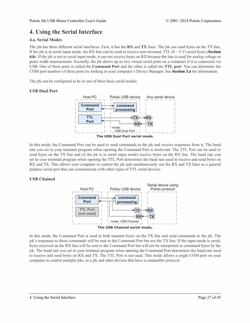
USB Dual Port
The USB Dual Port serial mode.
In this mode, the Command Port can be used to send commands to the jrk and receive responses from it. The baudrate you set in your terminal program when opening the Command Port is irrelevant. The TTL Port can be used tosend bytes on the TX line and (if the jrk is in serial input mode) receive bytes on the RX line. The baud rate youset in your terminal program when opening the TTL Port determines the baud rate used to receive and send bytes onRX and TX. This allows your computer to control the jrk and simultaneously use the RX and TX lines as a generalpurpose serial port that can communicate with other types of TTL serial devices.
USB Chained
The USB Chained serial mode.
In this mode, the Command Port is used to both transmit bytes on the TX line and send commands to the jrk. Thejrk’s responses to those commands will be sent to the Command Port but not the TX line. If the input mode is serial,bytes received on the RX line will be sent to the Command Port but will not be interpreted as command bytes by thejrk. The baud rate you set in your terminal program when opening the Command Port determines the baud rate usedto receive and send bytes on RX and TX. The TTL Port is not used. This mode allows a single COM port on yourcomputer to control multiple jrks, or a jrk and other devices that have a compatible protocol.
Pololu Jrk USB Motor Controller User's Guide © 2001–2014 Pololu Corporation
4. Using the Serial Interface Page 27 of 45
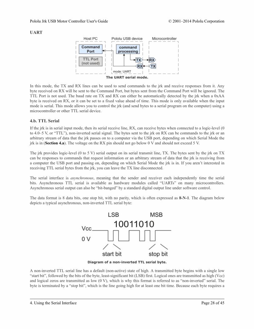
UART
The UART serial mode.
In this mode, the TX and RX lines can be used to send commands to the jrk and receive responses from it. Anybyte received on RX will be sent to the Command Port, but bytes sent from the Command Port will be ignored. TheTTL Port is not used. The baud rate on TX and RX can either be automatically detected by the jrk when a 0xAAbyte is received on RX, or it can be set to a fixed value ahead of time. This mode is only available when the inputmode is serial. This mode allows you to control the jrk (and send bytes to a serial program on the computer) using amicrocontroller or other TTL serial device.
4.b. TTL SerialIf the jrk is in serial input mode, then its serial receive line, RX, can receive bytes when connected to a logic-level (0to 4.0–5 V, or “TTL”), non-inverted serial signal. The bytes sent to the jrk on RX can be commands to the jrk or anarbitrary stream of data that the jrk passes on to a computer via the USB port, depending on which Serial Mode thejrk is in (Section 4.a). The voltage on the RX pin should not go below 0 V and should not exceed 5 V.
The jrk provides logic-level (0 to 5 V) serial output on its serial transmit line, TX. The bytes sent by the jrk on TXcan be responses to commands that request information or an arbitrary stream of data that the jrk is receiving froma computer the USB port and passing on, depending on which Serial Mode the jrk is in. If you aren’t interested inreceiving TTL serial bytes from the jrk, you can leave the TX line disconnected.
The serial interface is asynchronous, meaning that the sender and receiver each independently time the serialbits. Asynchronous TTL serial is available as hardware modules called “UARTs” on many microcontrollers.Asynchronous serial output can also be “bit-banged” by a standard digital output line under software control.
The data format is 8 data bits, one stop bit, with no parity, which is often expressed as 8-N-1. The diagram belowdepicts a typical asynchronous, non-inverted TTL serial byte:
Diagram of a non-inverted TTL serial byte.
A non-inverted TTL serial line has a default (non-active) state of high. A transmitted byte begins with a single low“start bit”, followed by the bits of the byte, least-significant bit (LSB) first. Logical ones are transmitted as high (Vcc)and logical zeros are transmitted as low (0 V), which is why this format is referred to as “non-inverted” serial. Thebyte is terminated by a “stop bit”, which is the line going high for at least one bit time. Because each byte requires a
Pololu Jrk USB Motor Controller User's Guide © 2001–2014 Pololu Corporation
4. Using the Serial Interface Page 28 of 45
start bit, 8 data bits, and a stop bit, each byte takes 10 bit times to transmit, so the fastest possible data rate in bytesper second is the baud rate divided by ten. At the jrk’s maximum baud rate of 115,200 bits per second, the maximumrealizable data rate, with a start bit coming immediately after the preceding byte’s stop bit, is 11,520 bytes per second.
Whenever connecting devices, remember to wire the grounds together, and ensure that each deviceis properly powered. Unpowered devices with a TTL serial port can turn on or partially on, drawingpower from the serial line, which means that extra care must be taken when turning power off and onto reset the devices.
4.c. Command ProtocolsYou can control the jrk by issuing serial commands.
If your jrk’s input mode is Serial and its Serial Mode is “UART, detect baud rate”, you must first send it the byte0xAA (170 in decimal) on the RX line (so it can detect the baud rate) before sending it any commands.
The jrk serial command protocol is fairly straightforward. Communication is achieved by sending command packetsconsisting of a single command byte followed by any data bytes that command requires. Command bytes always havetheir most significant bits set (i.e. they range from 128–255, or 0x80–0xFF in hex) while data bytes always have theirmost significant bits cleared (i.e. they range from 0–127, or 0x00–0x7F in hex). This means that each data byte canonly transmit seven bits of information.
The jrk responds to two sub-protocols:
Compact ProtocolThis is the simpler and more compact of the two protocols; it is the protocol you should use if your jrk is the onlydevice connected to your serial line. The jrk compact protocol command packet is simply:
command byte (with MSB set), any necessary data bytes
For example, if we want to set the target to 4080 (the highest value achievable using the low resolution Set Targetcommands), we could send the following byte sequence:
in hex: 0xE1, 0x7Fin decimal: 225, 127
The byte 0xE1 is the Set Target Low Resolution Forward command, and the data byte contains the motor speed.
Note that the Set Target High Resolution command uses some of the bits in the command byte to represent data, sothere is not a one-to-one correspondence between command bytes and commands.
Pololu ProtocolThis protocol is compatible with the serial protocol used by our other serial motor and servo controllers. As such,you can daisy-chain a jrk on a single serial line along with our other serial controllers (including additional jrks) and,using this protocol, send commands specifically to the desired jrk without confusing the other devices on the line.
The Pololu protocol is to transmit 0xAA (170 in decimal) as the first (command) byte, followed by a Device Numberdata byte. The default Device Number for the jrk is 11, but this is a configuration parameter you can change. Any
Pololu Jrk USB Motor Controller User's Guide © 2001–2014 Pololu Corporation
4. Using the Serial Interface Page 29 of 45
jrk on the line whose device number matches the specified device number accepts the command that follows; allother Pololu devices ignore the command. The remaining bytes in the command packet are the same as the compactprotocol command packet you would send, with one key difference: the compact protocol command byte is now adata byte for the command 0xAA and hence must have its most significant bit cleared. Therefore, the commandpacket is:
0xAA, device number byte, command byte with MSB cleared, any necessary data bytes
For example, if we want to set the target to 4080 for a jrk with device number 11, we could send the following bytesequence:
in hex: 0xAA, 0x0B, 0x61, 0x7Fin decimal: 170, 11, 97, 127
Note that 0x61 is the command 0xE1 with its most significant bit cleared.
The jrk responds to both the Pololu and Compact protocols on the fly; you do not need to use a configurationparameter to identify which protocol you are using.
4.d. Cyclic Redundancy Check (CRC) Error DetectionFor certain applications, verifying the integrity of the data you are sending and receiving can be very important.Because of this, the jrk has optional 7-bit cyclic redundancy checking, which is similar to a checksum but more robustas it can detect errors that would not affect a checksum, such as an extra zero byte or bytes out of order.
Cyclic redundancy checking can be enabled by checking the “Enable CRC” checkbox in the configuration utility. InCRC mode, the jrk expects an extra byte to be added onto the end of every command packet. The most-significant bitof this byte must be cleared, and the seven least-significant bits must be the 7-bit CRC for that packet. If this CRCbyte is incorrect, the jrk will generate its Serial CRC error and ignore the command. The jrk does not append a CRCbyte to the data it transmits in response to serial commands.
A detailed account of how cyclic redundancy checking works is beyond the scope of this document, but you can finda wealth of information using Wikipedia [http://en.wikipedia.org/wiki/Cyclic_redundancy_check]. The CRC computation isbasically a carryless long division of a CRC “polynomial”, 0x91, into your message (expressed as a continuous streamof bits), where all you care about is the remainder. The jrk uses CRC-7, which means it uses an 8-bit polynomial and,as a result, produces a 7-bit remainder. This remainder is the lower 7 bits of the CRC byte you tack onto the end ofyour command packets.
The CRC implemented on the jrk is the same as the one on the qik [http://www.pololu.com/product/1110]motor controller but differs from that on the TReX [http://www.pololu.com/product/777] motor controller.Instead of being done MSB first, the computation is performed LSB first to match the order in whichthe bits are transmitted over the serial line. In standard binary notation, the number 0x91 is written as10010001. However, the bits are transmitted in this order: 1, 0, 0, 0, 1, 0, 0, 1, so we will write it as10001001 to carry out the computation below.
The CRC-7 algorithm is as follows:
1. Express your 8-bit CRC-7 polynomial and message in binary, LSB first. The polynomial 0x91 is written as10001001.
Pololu Jrk USB Motor Controller User's Guide © 2001–2014 Pololu Corporation
4. Using the Serial Interface Page 30 of 45
2. Add 7 zeros to the end of your message.
3. Write your CRC-7 polynomial underneath the message so that the LSB of your polynomial is directly belowthe LSB of your message.
4. If the LSB of your CRC-7 is aligned under a 1, XOR the CRC-7 with the message to get a new message; ifthe LSB of your CRC-7 is aligned under a 0, do nothing.
5. Shift your CRC-7 right one bit. If all 8 bits of your CRC-7 polynomial still line up underneath message bits,go back to step 4.
6. What’s left of your message is now your CRC-7 result (transmit these seven bits as your CRC byte whentalking to the jrk with CRC enabled).
If you have never encountered CRCs before, this probably sounds a lot more complicated than it really is. Thefollowing example shows that the CRC-7 calculation is not that difficult. For the example, we will use a two-bytesequence: 0x83, 0x01.
Steps 1 & 2 (write as binary, add 7 zeros to the end of the message):
CRC-7 Polynomial = [1 0 0 0 1 0 0 1]message = [1 1 0 0 0 0 0 1] [1 0 0 0 0 0 0 0] 0 0 0 0 0 0 0
Steps 3, 4, & 5:_______________________________________________
1 0 0 0 1 0 0 1 ) 1 1 0 0 0 0 0 1 1 0 0 0 0 0 0 0 0 0 0 0 0 0 0XOR 1 0 0 0 1 0 0 1 | | | | | | | | | | | | | | |
--------------- | | | | | | | | | | | | | | |1 0 0 1 0 0 0 1 | | | | | | | | | | | | | |
shift ----> 1 0 0 0 1 0 0 1 | | | | | | | | | | | | | |_______________ | | | | | | | | | | | | | |
1 1 0 0 0 0 0 0 | | | | | | | | | | |1 0 0 0 1 0 0 1 | | | | | | | | | | |_______________ | | | | | | | | | | |
1 0 0 1 0 0 1 0 | | | | | | | | | |1 0 0 0 1 0 0 1 | | | | | | | | | |_______________ | | | | | | | | | |
1 1 0 1 1 0 0 0 | | | | | | |1 0 0 0 1 0 0 1 | | | | | | |_______________ | | | | | | |
1 0 1 0 0 0 1 0 | | | | | |1 0 0 0 1 0 0 1 | | | | | |_______________ | | | | | |
1 0 1 0 1 1 0 0 | | | |1 0 0 0 1 0 0 1 | | | |_______________ | | | |
1 0 0 1 0 1 0 0 | |1 0 0 0 1 0 0 1 | |_______________ | |
1 1 1 0 1 0 0 = 0x17
So the full command packet we would send with CRC enabled is: 0x83, 0x01, 0x17.
4.e. Motor Control CommandsThe jrk has several serial commands for turning the motor on and off and setting the target. These commands aremainly intended to be used in serial input mode, but they can be used in any input mode to turn the motor on or offfrom a computer.
Motor OffCompact protocol: 0xFFPololu protocol: 0xAA, device number, 0x7F
Pololu Jrk USB Motor Controller User's Guide © 2001–2014 Pololu Corporation
4. Using the Serial Interface Page 31 of 45
This command will turn the motor off by setting the Awaiting Command error bit. The jrk will not restart the motoruntil it receives a Set Target command. The jrk can be configured to either brake or coast while the motor is off(Section 3.e).
Set Target High ResolutionCompact protocol, binary: 110LLLLL, 0HHHHHHHCompact protocol, hex: 0xC0 + target low 5 bits, target high 7 bitsPololu protocol, binary: 10101010, device number, 010LLLLL, 0HHHHHHHPololu protocol, hex: 0xAA, device number, 0x40 + target low 5 bits, target high 7 bits(where target is the 12-bit number HHHHHHHLLLLL)
This command clears the Awaiting Command error bit and (if Input Mode is Serial) lets you set the 12-bit target toany of its allowed values (0–4095). The meaning of the target depends on what Feedback Mode the jrk is in (Section3.c). The lower 5 bits of the command byte represent the lower 5 bits of the target, while the lower 7 bits of the databyte represent the upper 7 bits of the target.
For example, if you want to set the target to 3229 (110010011101 in binary), you could send the following bytesequence:
in binary: 11011101, 01100100in hex: 0xDD, 0x64in decimal: 221, 100
Here is some example C code that will generate the correct serial bytes, given an integer “target” that holds the desiredtarget (0–4095) and an array called serialBytes:
serialBytes[0] = 0xC0 + (target & 0x1F); // Command byte holds the lower 5 bits of target.serialBytes[1] = (target >> 5) & 0x7F; // Data byte holds the upper 7 bits of target.
Many motor control applications do not need 12 bits of target resolution. If you want a simpler and lower-resolutionset of commands for setting the target, you can use the Set Target Low Resolution commands. Alternatively, youcould use the Set Target High Resolution command with the lower 5 bits of the target always zero: sending a 0xC0byte followed by a data byte (0–127) will result in setting the target to a value of 32 multiplied by the data byte.
Set Target Low Resolution ForwardCompact protocol: 0xE1, magnitudePololu protocol: 0xAA, device number, 0x61, magnitude
This command clears the Awaiting Command error bit and (if Input Mode is Serial) sets the target to a value of 2048or greater which is determined by the magnitude (0–127).
If the Feedback Mode is Analog or Tachometer, then the formula is
Target = 2048 + 16×magnitude.
If the Feedback Mode is None (speed control mode), then the formula is
Target = 2048 + (600/127)×magnitude.
This means that a magnitude of 127 will set the duty cycle target to full-speed forward (+600), while a magnitude ofzero will make the motor stop.
Pololu Jrk USB Motor Controller User's Guide © 2001–2014 Pololu Corporation
4. Using the Serial Interface Page 32 of 45
Set Target Low Resolution ReverseCompact protocol: 0xE0, magnitudePololu protocol: 0xAA, device number, 0x60, magnitude
If magnitude is zero, then this command is equivalent to the Motor Off command above: the Awaiting Commanderror bit will be set, so the jrk will turn the motor off until another Set Target command is received.
Otherwise, this command clears the Awaiting Command error bit and (if Input Mode is Serial) sets the target to avalue less than 2048 which is determined by the magnitude (0–127).
If the Feedback Mode is Analog or Tachometer, then the formula is
Target = 2048 − 16×magnitude.
If the Feedback Mode is None (speed control mode), then the formula is
Target = 2048 − (600/127)×magnitude.
This means that a magnitude of 127 will set the duty cycle target to full-speed reverse (-600).
4.f. Error Reporting CommandsThere are several errors that can stop the jrk from driving its motor. The jrk’s response to the different errors can beconfigured (Section 3.f).
Both of the error reporting commands result in a two-byte serial response form the jrk. Each bit in those two bytesrepresents a particular error. If the bit is 1, it means that the error occurred or is occurring. If we call the least-significant bit 0, and the first byte transmitted contains bits 0-7, then the correspondence between bits of the errorbytes and errors are as follows:
• Bit 0: Awaiting commandIf this bit is set, the jrk will not drive the motor until it receives a command that clears this bit. Any version ofthe Set Target command will clear the error bit. A Set Target command can be sent from the configuration utility,from a computer using the virtual Command Port (unless the jrk is configured to receive commands on RX), orfrom the RX line if the jrk is configured to receive commands on RX. This error occurs in Serial Input modewhen the Jrk is powered on.
• Bit 1: No powerThis error occurs when the jrk is connected to USB, but it detects no motor power connected to VIN and GND,so it can not drive the motor. If this error occurs, check your power supply and power connections.
• Bit 2: Motor driver errorThis error occurs when one of the motor driver’s fault conditions are triggered, and the motor driver shuts downthe motor and reports the error to the jrk’s microcontroller. This error also occurs when the jrk is connected toUSB and motor power becomes disconnected. When this error occurs, the jrk will try to automatically recoverfrom it by toggling the appropriate lines on the motor driver. The jrk 21v3’s motor driver fault occurs on under-voltage, over-temperature, or over-current conditions. The jrk 12v12’s motor driver fault occurs when it detectsthat motor output A is shorted to ground or VIN.
• Bit 3: Input invalid (Pulse Width Input Mode only)In Pulse Width Input Mode, the jrk will only update the input value if it has received four good pulses in a row.For example, if the jrk receives five good pulses, a bad pulse, and then five more good pulses, it will update theinput value after pulses 4, 5, 10, and 11. This error occurs if the jrk goes more than 120 ms without updating the
Pololu Jrk USB Motor Controller User's Guide © 2001–2014 Pololu Corporation
4. Using the Serial Interface Page 33 of 45
input value. The jrk can recover from the error by receiving four good pulses in a row. This error does not occurin Analog Input Mode or Serial Input Mode.
• Bit 4: Input disconnectThis error occurs when the input is above the Absolute maximum or below the Absolute minimum (theseparameters can be set in the configuration utility). Additionally, when using the Detect disconnect with AUXoption in Analog Input Mode, the jrk periodically tests to see whether the input potentiometer is disconnectedand generates this error if it finds that it is (Section 3.b).
• Bit 5: Feedback disconnectThis error occurs when the feedback is above the Absolute maximum or below the Absolute minimum (theseparameters can be set in the configuration utility). The absolute maximum and absolute minimum can be setusing the configuration utility. Additionally, when using the Detect disconnect with AUX option in AnalogFeedback Mode, the jrk periodically tests to see whether the feedback potentiometer is disconnected andgenerates this error if it finds that it is (Section 3.c).
• Bit 6: Maximum current exceededThis error occurs when the motor current limit is exceeded. The limit can be set using the configuration utility(Section 3.e).
• Bit 7: Serial signal errorA hardware-level error that occurs when a byte’s stop bit is not detected at the expected place. This can occur ifyou are communicating at a baud rate that differs from the jrk’s baud rate.
• Bit 8: Serial overrunA hardware-level error that occurs when the UART receive buffer is full. This error should not occur duringnormal operation.
• Bit 9: Serial RX buffer fullA firmware-level error that occurs when the firmware’s buffer for bytes received on the RX line is full and a bytefrom RX has been lost as a result. This error should not occur during normal operation.
• Bit 10: Serial CRC errorThis error occurs when the jrk is running in CRC-enabled mode and the cyclic redundancy check (CRC) byte atthe end of the command packet does not match what the jrk has computed as that packet’s CRC (Section 4.d).In such a case, the jrk ignores the command packet and generates a CRC error.
• Bit 11: Serial protocol errorThis error occurs when the jrk receives an incorrectly formatted or nonsensical command packet. For example,if the command byte does not match a known command or an unfinished command packet is interrupted byanother command packet, this error occurs.
• Bit 12: Serial timeout errorWhen the serial timeout is enabled (Section 3.b), this error occurs whenever the timeout period has elapsedwithout the jrk receiving any valid serial commands. This timeout error can be used to shut down the motors inthe event that serial communication between the jrk and its controller is disrupted.
• Bits 13-15: ReservedThese bits do not represent any errors; they will always read as zeroes.
Get Error Flags HaltingCompact protocol: 0xB3Pololu protocol: 0xAA, device number, 0x33
This command generates a two-byte serial response reporting which errors are currently stopping the motor, andit clears the corresponding error bits (except for the Awaiting Command error bit). This command is useful fordetermining why your motor is not turning, and for clearing any latched errors that are enabled. This command willnot report any errors that have been disabled in the configuration utility, because those errors do not stop the motor.
Pololu Jrk USB Motor Controller User's Guide © 2001–2014 Pololu Corporation
4. Using the Serial Interface Page 34 of 45
This command is equivalent to reading the “Currently stopping motor?” column in the Errors tab of the configurationutility, and then clicking the “Clear Errors” button.
If an error is stopping the motor (besides the Awaiting Command error bit), the jrk will turn the red LED on and drivethe ERR line high, and this command can be used to determine the cause of the error.
Get Error Flags OccurredCompact protocol: 0xB5Pololu protocol: 0xAA, device number, 0x35
This command generates a two-byte serial response reporting which errors have occurred since the last time the GetError Flags Occurred command was received. Unlike the Get Error Flags Halting command, this command has noeffect on the motor.
Note: If the jrk is connected to the configuration utility, then the Get Error Flags Occurred commandwill give unreliable responses, because the configuration utility runs this command regularly. Thiscommand will report all the errors that have occurred since the last time the Get Error Flags Occurredcommand was received, regardless of whether that last command came from the configuration utility,from your microcontroller, or from the jrk’s virtual Command Port.
4.g. Variable Reading CommandsCompact protocol: read variable command bytePololu protocol: 0xAA, device number, read variable command byte with MSB clear
The jrk has several serial commands for reading its variables. Most of the variables are two bytes long. For each ofthose variables, three variable reading commands are provided:
• Two bytes: These commands will result in a two-byte serial response from the jrk containing both bytes ofthe variable. All variables are little endian, so the first byte transmitted will be the least-significant byte, and thesecond byte transmitted will be the most-significant byte. For variables that can have negative values, the two’scomplement system is used (a response of 0xFE, 0xFF means -2).
• Low byte: These commands will result in a one-byte serial response from the jrk containing just the least-significant byte of the variable.
• High byte: These commands will result in a one-byte serial response from the jrk containing just the most-significant byte of the variable.
The command bytes are listed in the table below.
Pololu Jrk USB Motor Controller User's Guide © 2001–2014 Pololu Corporation
4. Using the Serial Interface Page 35 of 45
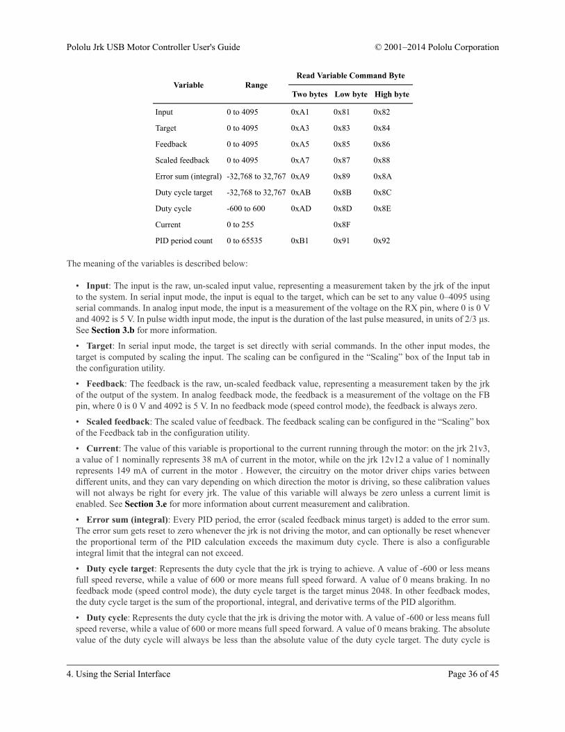
Read Variable Command ByteVariable Range
Two bytes Low byte High byte
Input 0 to 4095 0xA1 0x81 0x82
Target 0 to 4095 0xA3 0x83 0x84
Feedback 0 to 4095 0xA5 0x85 0x86
Scaled feedback 0 to 4095 0xA7 0x87 0x88
Error sum (integral) -32,768 to 32,767 0xA9 0x89 0x8A
Duty cycle target -32,768 to 32,767 0xAB 0x8B 0x8C
Duty cycle -600 to 600 0xAD 0x8D 0x8E
Current 0 to 255 0x8F
PID period count 0 to 65535 0xB1 0x91 0x92
The meaning of the variables is described below:
• Input: The input is the raw, un-scaled input value, representing a measurement taken by the jrk of the inputto the system. In serial input mode, the input is equal to the target, which can be set to any value 0–4095 usingserial commands. In analog input mode, the input is a measurement of the voltage on the RX pin, where 0 is 0 Vand 4092 is 5 V. In pulse width input mode, the input is the duration of the last pulse measured, in units of 2/3 μs.See Section 3.b for more information.
• Target: In serial input mode, the target is set directly with serial commands. In the other input modes, thetarget is computed by scaling the input. The scaling can be configured in the “Scaling” box of the Input tab inthe configuration utility.
• Feedback: The feedback is the raw, un-scaled feedback value, representing a measurement taken by the jrkof the output of the system. In analog feedback mode, the feedback is a measurement of the voltage on the FBpin, where 0 is 0 V and 4092 is 5 V. In no feedback mode (speed control mode), the feedback is always zero.
• Scaled feedback: The scaled value of feedback. The feedback scaling can be configured in the “Scaling” boxof the Feedback tab in the configuration utility.
• Current: The value of this variable is proportional to the current running through the motor: on the jrk 21v3,a value of 1 nominally represents 38 mA of current in the motor, while on the jrk 12v12 a value of 1 nominallyrepresents 149 mA of current in the motor . However, the circuitry on the motor driver chips varies betweendifferent units, and they can vary depending on which direction the motor is driving, so these calibration valueswill not always be right for every jrk. The value of this variable will always be zero unless a current limit isenabled. See Section 3.e for more information about current measurement and calibration.
• Error sum (integral): Every PID period, the error (scaled feedback minus target) is added to the error sum.The error sum gets reset to zero whenever the jrk is not driving the motor, and can optionally be reset wheneverthe proportional term of the PID calculation exceeds the maximum duty cycle. There is also a configurableintegral limit that the integral can not exceed.
• Duty cycle target: Represents the duty cycle that the jrk is trying to achieve. A value of -600 or less meansfull speed reverse, while a value of 600 or more means full speed forward. A value of 0 means braking. In nofeedback mode (speed control mode), the duty cycle target is the target minus 2048. In other feedback modes,the duty cycle target is the sum of the proportional, integral, and derivative terms of the PID algorithm.
• Duty cycle: Represents the duty cycle that the jrk is driving the motor with. A value of -600 or less means fullspeed reverse, while a value of 600 or more means full speed forward. A value of 0 means braking. The absolutevalue of the duty cycle will always be less than the absolute value of the duty cycle target. The duty cycle is
Pololu Jrk USB Motor Controller User's Guide © 2001–2014 Pololu Corporation
4. Using the Serial Interface Page 36 of 45
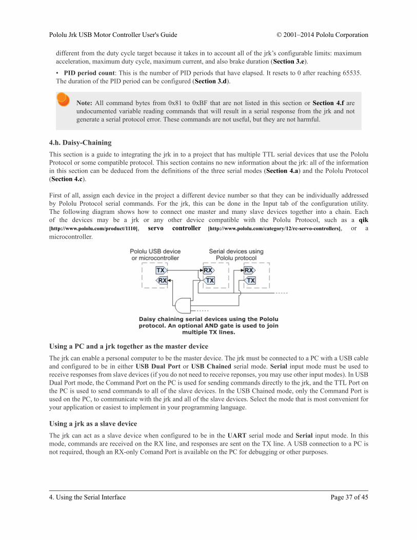
different from the duty cycle target because it takes in to account all of the jrk’s configurable limits: maximumacceleration, maximum duty cycle, maximum current, and also brake duration (Section 3.e).
• PID period count: This is the number of PID periods that have elapsed. It resets to 0 after reaching 65535.The duration of the PID period can be configured (Section 3.d).
Note: All command bytes from 0x81 to 0xBF that are not listed in this section or Section 4.f areundocumented variable reading commands that will result in a serial response from the jrk and notgenerate a serial protocol error. These commands are not useful, but they are not harmful.
4.h. Daisy-ChainingThis section is a guide to integrating the jrk in to a project that has multiple TTL serial devices that use the PololuProtocol or some compatible protocol. This section contains no new information about the jrk: all of the informationin this section can be deduced from the definitions of the three serial modes (Section 4.a) and the Pololu Protocol(Section 4.c).
First of all, assign each device in the project a different device number so that they can be individually addressedby Pololu Protocol serial commands. For the jrk, this can be done in the Input tab of the configuration utility.The following diagram shows how to connect one master and many slave devices together into a chain. Eachof the devices may be a jrk or any other device compatible with the Pololu Protocol, such as a qik[http://www.pololu.com/product/1110], servo controller [http://www.pololu.com/category/12/rc-servo-controllers], or amicrocontroller.
Daisy chaining serial devices using the Pololuprotocol. An optional AND gate is used to join
multiple TX lines.
Using a PC and a jrk together as the master deviceThe jrk can enable a personal computer to be the master device. The jrk must be connected to a PC with a USB cableand configured to be in either USB Dual Port or USB Chained serial mode. Serial input mode must be used toreceive responses from slave devices (if you do not need to receive reponses, you may use other input modes). In USBDual Port mode, the Command Port on the PC is used for sending commands directly to the jrk, and the TTL Port onthe PC is used to send commands to all of the slave devices. In the USB Chained mode, only the Command Port isused on the PC, to communicate with the jrk and all of the slave devices. Select the mode that is most convenient foryour application or easiest to implement in your programming language.
Using a jrk as a slave deviceThe jrk can act as a slave device when configured to be in the UART serial mode and Serial input mode. In thismode, commands are received on the RX line, and responses are sent on the TX line. A USB connection to a PC isnot required, though an RX-only Comand Port is available on the PC for debugging or other purposes.
Pololu Jrk USB Motor Controller User's Guide © 2001–2014 Pololu Corporation
4. Using the Serial Interface Page 37 of 45
ConnectionsConnect the TX line of the master device to the RX lines of all of the slave devices. Commands sent by the masterwill then be received by all slaves.
Receiving serial responses from one the slave devices on the PC can be achieved by connecting the TX line of thatslave device to the RX line of the jrk.
Receiving serial responses from multiple slave devices is more complicated. Each device should only transmit whenrequested, so if each device is addressed separately, multiple devices will not transmit simultaneously. However, theTX outputs are driven high when not sending data, so they cannot simply be wired together. Instead, you can usean AND gate, as shown in the diagram, to combine the signals. Note that in many cases receiving responses is notnecessary, and the TX lines can be left unconnected.
If there are multiple slave jrks, you can connect all of the jrks’ ERR lines to a single input on a microcontroller tomonitor the error state.
Whenever connecting devices, remember to wire the grounds together, and ensure that each deviceis properly powered. Unpowered devices with a TTL serial port can turn on or partially on, drawingpower from the serial line, which means that extra care must be taken when turning power off and onto reset the devices.
Sending commandsThe Pololu Protocol should be used when multiple Pololu devices are receiving the same serial data. This allows thedevices to be individually addressed, and it allows responses to be sent without collisions.
If the devices are configured to detect the baud rate, then when you issue your first Pololu Protocol command, thedevices can automatically detect the baud from the initial 0xAA byte.
Some older Pololu devices use 0x80 as an initial command byte. If you want to chain these together with devicesexpecting 0xAA, you should first transmit the byte 0x80 so that these devices can automatically detect the baud rate,and only then should you send the byte 0xAA so that the jrk can detect the baud rate. Once all devices have detectedthe baud rate, Pololu devices that expect a leading command byte of 0x80 will ignore command packets that start with0xAA, and jrks will ignore command packets that start with 0x80.
4.i. Serial Example Code4.i.1. Cross-platform CThe example C code below works on Windows, Linux, and Mac OS X 10.7 or later. It demonstrates how to set thetarget of a jrk by sending a Set Target command to its Command Port, and how to read variables from the jrk. Thejrk’s input mode must be set to “Serial” and the serial mode must be “USB Dual Port” for this code to work. You willalso need to modify the line that specifies the name of the COM port device.
This code will work in Windows if compiled with MinGW, but it does not work with the Microsoft Ccompiler. For Windows-specific example code that works with either compiler, see Section 4.i.2.
// Uses POSIX functions to send and receive data from a jrk.// NOTE: The jrk's input mode must be "Serial".// NOTE: The jrk's serial mode must be set to "USB Dual Port".// NOTE: You must change the 'const char * device' line below.
Pololu Jrk USB Motor Controller User's Guide © 2001–2014 Pololu Corporation
4. Using the Serial Interface Page 38 of 45
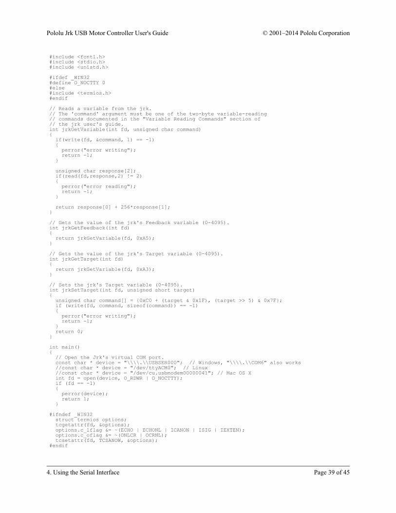
#include <fcntl.h>#include <stdio.h>#include <unistd.h>
#ifdef _WIN32#define O_NOCTTY 0#else#include <termios.h>#endif
// Reads a variable from the jrk.// The 'command' argument must be one of the two-byte variable-reading// commands documented in the "Variable Reading Commands" section of// the jrk user's guide.int jrkGetVariable(int fd, unsigned char command){
if(write(fd, &command, 1) == -1){
perror("error writing");return -1;
}
unsigned char response[2];if(read(fd,response,2) != 2){
perror("error reading");return -1;
}
return response[0] + 256*response[1];}
// Gets the value of the jrk's Feedback variable (0-4095).int jrkGetFeedback(int fd){
return jrkGetVariable(fd, 0xA5);}
// Gets the value of the jrk's Target variable (0-4095).int jrkGetTarget(int fd){
return jrkGetVariable(fd, 0xA3);}
// Sets the jrk's Target variable (0-4095).int jrkSetTarget(int fd, unsigned short target){
unsigned char command[] = {0xC0 + (target & 0x1F), (target >> 5) & 0x7F};if (write(fd, command, sizeof(command)) == -1){
perror("error writing");return -1;
}return 0;
}
int main(){
// Open the Jrk's virtual COM port.const char * device = "\\\\.\\USBSER000"; // Windows, "\\\\.\\COM6" also works//const char * device = "/dev/ttyACM0"; // Linux//const char * device = "/dev/cu.usbmodem00000041"; // Mac OS Xint fd = open(device, O_RDWR | O_NOCTTY);if (fd == -1){
perror(device);return 1;
}
#ifndef _WIN32struct termios options;tcgetattr(fd, &options);options.c_lflag &= ~(ECHO | ECHONL | ICANON | ISIG | IEXTEN);options.c_oflag &= ~(ONLCR | OCRNL);tcsetattr(fd, TCSANOW, &options);
#endif
Pololu Jrk USB Motor Controller User's Guide © 2001–2014 Pololu Corporation
4. Using the Serial Interface Page 39 of 45
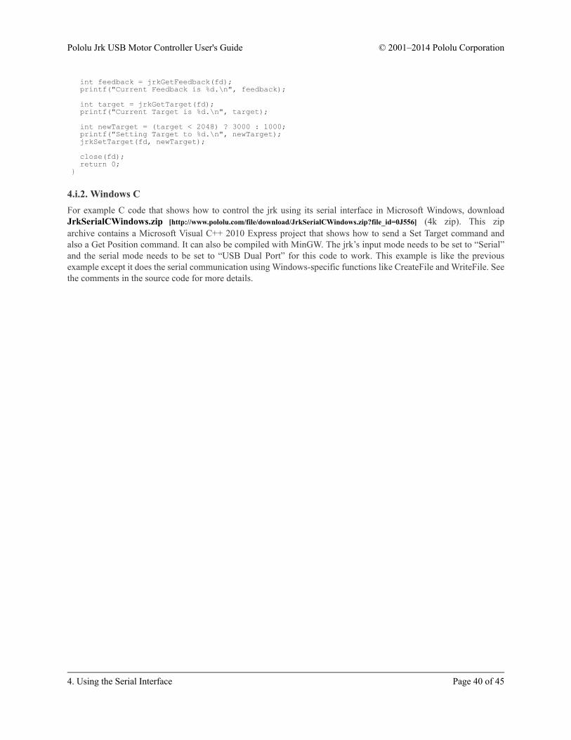
int feedback = jrkGetFeedback(fd);printf("Current Feedback is %d.\n", feedback);
int target = jrkGetTarget(fd);printf("Current Target is %d.\n", target);
int newTarget = (target < 2048) ? 3000 : 1000;printf("Setting Target to %d.\n", newTarget);jrkSetTarget(fd, newTarget);
close(fd);return 0;
}
4.i.2. Windows CFor example C code that shows how to control the jrk using its serial interface in Microsoft Windows, downloadJrkSerialCWindows.zip [http://www.pololu.com/file/download/JrkSerialCWindows.zip?file_id=0J556] (4k zip). This ziparchive contains a Microsoft Visual C++ 2010 Express project that shows how to send a Set Target command andalso a Get Position command. It can also be compiled with MinGW. The jrk’s input mode needs to be set to “Serial”and the serial mode needs to be set to “USB Dual Port” for this code to work. This example is like the previousexample except it does the serial communication using Windows-specific functions like CreateFile and WriteFile. Seethe comments in the source code for more details.
Pololu Jrk USB Motor Controller User's Guide © 2001–2014 Pololu Corporation
4. Using the Serial Interface Page 40 of 45
5. Setting Up Your SystemThe following step-by-step procedure is recommended for configuring a feedback system for use with a jrk motorcontroller.
Connecting power and feedback1. Connect your jrk to a PC with a USB cable and launch the configuration utility. The red LED should be on.
2. Select the “Reset to default settings…” option from the File menu to load a safe set of settings.
3. With your power supply off, make the power connections to VIN and GND.
4. Connect your feedback sensor to the FB input. If you are using a potentiometer as a feedback sensor, use theAUX pin to power it, and enable Detect disconnect with AUX in the Feedback tab.
5. Set the “No power”, “Motor driver error”, “Feedback disconnect”, and “Max. current exceeded” errors onthe Error tab to Enabled and latched. This should stop your system in case of any major problem.
6. Click “Apply settings to device”.
7. Turn on power.
8. On the Error tab, click “Clear Errors” to remove the errors caused by turning off the power.
The red LED should now be off, and the yellow LED should be blinking slowly, indicating that the board has powerbut that no target has been set. If the red LED is on, examine the Errors tab to determine the source of the problem.Look at the value of Scaled Feedback displayed at the top of the window, and verify that it changes if you manuallyadjust the feedback sensor.
Calibrating feedback1. Select the correct value for Feedback mode.
2. Click “Learn…” on the Feedback tab. You will be prompted to turn the output to its minimum and maximumpositions, so that readings of the feedback sensor can be determined at each extreme.
3. Examine the resulting values and adjust if desired. Your system will be safer if you set Absolute Max. andAbsolute Min. to values that the system can actually reach, so that if motion takes it past those extremes, the jrkwill automatically shut down (because of the “Feedback disconnect” error.)
4. Click “Apply settings to device”.
5. Move the system to the middle of its range.
Setting motor limits1. Set Max. duty cycle to a safe value, like 200.
2. Set Max. current to a safe value, like 500 mA. You want values that will turn the motor but not give it enoughpower to do any damage if something goes wrong.
3. Set other limits as necessary.
4. Click “Apply settings to device”.
Connecting the motor
From this point on, be prepared to shut down the system by clicking “Stop motor” or turning off yourpower supply if anything goes wrong and the limits and errors set previously fail to stop the motor.
Pololu Jrk USB Motor Controller User's Guide © 2001–2014 Pololu Corporation
5. Setting Up Your System Page 41 of 45
1. Turn off power.
2. Connect your motor wires to the jrk’s A and B motor outputs. If possible, connect them so that positivevoltage at A causes the motor to drive forward.
3. Turn on power.
Testing the motor1. If possible, drive your motor with feedback disabled. To do this, make sure that the Feedback mode is set tonone and use the controls on the Input tab to apply different duty cycles. Of course, this requires you to have asystem that does not destroy itself when run without feedback.
2. On the Error tab, click “Clear Errors” to remove the errors caused by turning off the power.
3. On the Motor tab, click the “Detect Motor Direction” button. This will apply some power to the motor andmeasure the direction that feedback moves in response. If the motor is connected “reversed” with respect to yourfeedback sensor, then Invert motor direction will be checked.
4. Click “Apply settings to device” to apply any changes.
Testing basic feedback1. In the PID tab, choose a Proportional Coefficient of 1 and leave the other two constants at zero. This willprobably drive your motor at its maximum duty cycle, so make sure that this and other motor parameters areconfigured correctly.
2. Click “Apply settings to device”.
3. Use the slider on the Input tab to send various input values to your jrk, and see how it behaves.
If you did everything correctly, your feedback system should now be active, approximately following the target value.
Tuning the PID constantsTuning PID constants is a complicated process that can be approached in many different ways. Here we will give abasic procedure that works for some systems, but you will probably want to try various different methods for findingthe best possible values. You will want to have the Plots window open, displaying a nice view of the Error, Target,Scaled Feedback, and Duty Cycle. When setting the Integral Coefficient, it will also be useful to look at the value ofthe Integral.
1. Increase your Max. duty cycle, Max. current, and other limits to reasonable values for high-performanceoperation of your system.
2. Try increasing the Proportional Coefficient until you reach a point where the system becomes unstable. Notethat the stability could be different at different target positions, so try the full range of motion when hunting forinstability.
3. Decrease the value from the point of instability by about 40-50%. This is the first step of the Ziegler-NicholsMethod [http://en.wikipedia.org/wiki/Ziegler%E2%80%93Nichols_method].
Pololu Jrk USB Motor Controller User's Guide © 2001–2014 Pololu Corporation
5. Setting Up Your System Page 42 of 45
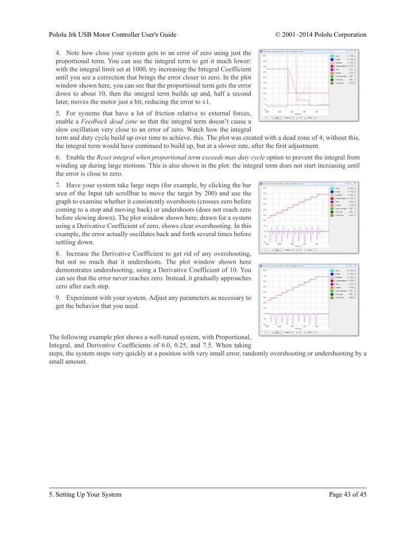
4. Note how close your system gets to an error of zero using just theproportional term. You can use the integral term to get it much lower:with the integral limit set at 1000, try increasing the Integral Coefficientuntil you see a correction that brings the error closer to zero. In the plotwindow shown here, you can see that the proportional term gets the errordown to about 10, then the integral term builds up and, half a secondlater, moves the motor just a bit, reducing the error to ±1.
5. For systems that have a lot of friction relative to external forces,enable a Feedback dead zone so that the integral term doesn’t cause aslow oscillation very close to an error of zero. Watch how the integralterm and duty cycle build up over time to achieve. this. The plot was created with a dead zone of 4; without this,the integral term would have continued to build up, but at a slower rate, after the first adjustment.
6. Enable the Reset integral when proportional term exceeds max duty cycle option to prevent the integral fromwinding up during large motions. This is also shown in the plot: the integral term does not start increasing untilthe error is close to zero.
7. Have your system take large steps (for example, by clicking the bararea of the Input tab scrollbar to move the target by 200) and use thegraph to examine whether it consistently overshoots (crosses zero beforecoming to a stop and moving back) or undershoots (does not reach zerobefore slowing down). The plot window shown here, drawn for a systemusing a Derivative Coefficient of zero, shows clear overshooting. In thisexample, the error actually oscillates back and forth several times beforesettling down.
8. Increase the Derivative Coefficient to get rid of any overshooting,but not so much that it undershoots. The plot window shown heredemonstrates undershooting, using a Derivative Coefficient of 10. Youcan see that the error never reaches zero. Instead, it gradually approacheszero after each step.
9. Experiment with your system. Adjust any parameters as necessary toget the behavior that you need.
The following example plot shows a well-tuned system, with Proportional,Integral, and Derivative Coefficients of 6.0, 0.25, and 7.5. When takingsteps, the system stops very quickly at a position with very small error, randomly overshooting or undershooting by asmall amount.
Pololu Jrk USB Motor Controller User's Guide © 2001–2014 Pololu Corporation
5. Setting Up Your System Page 43 of 45
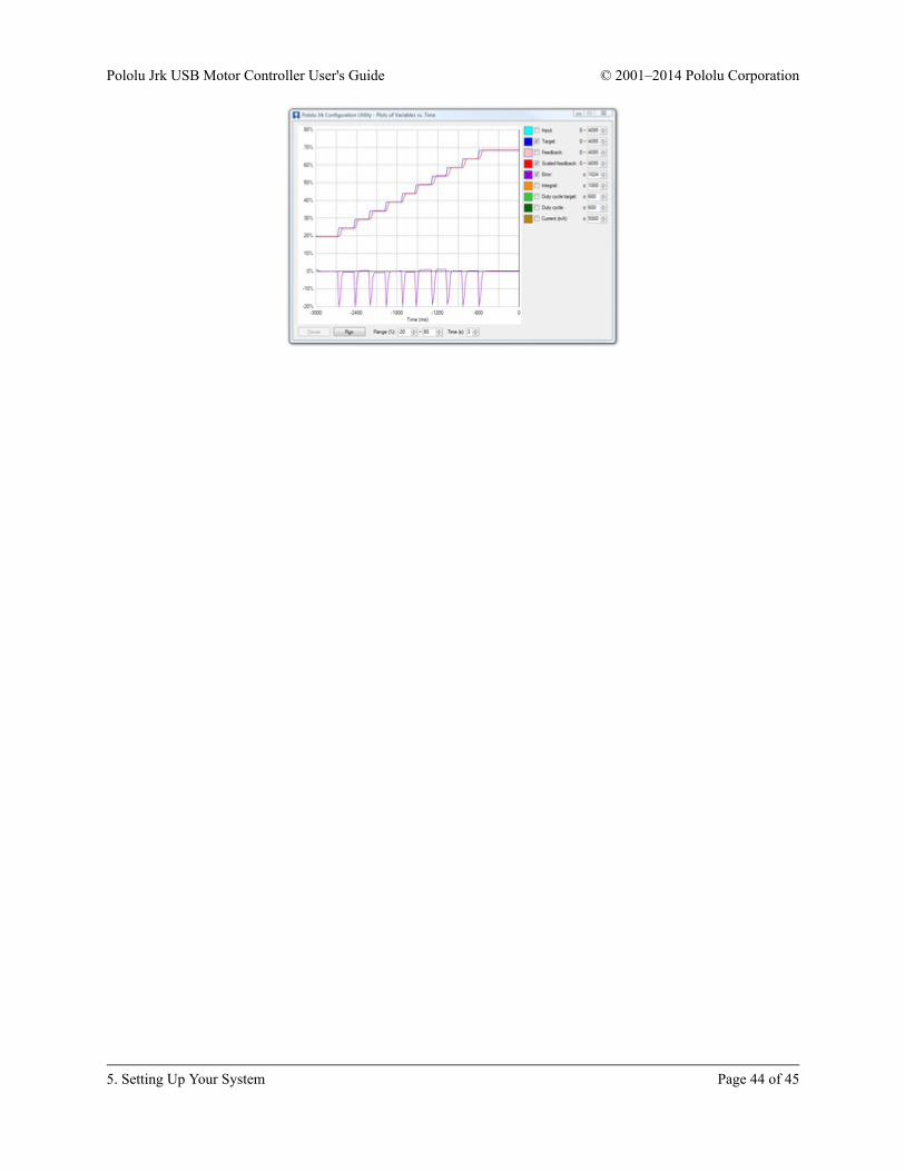
Pololu Jrk USB Motor Controller User's Guide © 2001–2014 Pololu Corporation
5. Setting Up Your System Page 44 of 45

6. Writing PC Software to Control the JrkThere are two ways to write PC software to control the jrk: the native USB interface and the virtual serial port.The native USB interface provides more features than the serial port, such as the ability to change configurationparameters and select the jrk by its serial number. Also, the USB interface allows you to recover more easily fromtemporary disconnections. The virtual serial port interface is easier to use if you are not familiar with programming,and it can work with existing software programs that use serial ports, such as LabView.
Native USB InterfaceThe Pololu USB Software Development Kit [http://www.pololu.com/docs/0J41] supports Windows and Linux, andincludes C# source code for:
• JrkExample: an example graphical application that uses native USB to send commands and receive feedbackfrom the jrk and automatically recover from disconnection.
• JrkCmd: a command-line utility for configuring and controlling the jrk. JrkCmd has a streaming mode thatallows you to steadily stream all of the jrk variables to the computer and output them in comma-separated formatin case you want to make your own graphs or do something special with the data.
• C# .NET class libraries that enable native USB communication with the jrk.
You can modify the applications in the SDK to suit your needs or you can use the class libraries to integrate thejrk in to your own applications. Advanced users can also use the source code as a reference when writing customapplications in any language that control the jrk over USB.
Virtual Serial PortsAlmost any programming language is capable of accessing the COM ports created by the jrk. We recommend theMicrosoft .NET framework, which is free to use and contains a SerialPort class that makes it easy to read and writebytes from a serial port. You can download Visual Studio Express (for either C#, C++, or Visual Basic) and writeprograms that use the SerialPort class to communicate with the jrk. You will need to set the jrk’s serial mode to beeither “USB Dual Port” or “USB Chained”.
Pololu Jrk USB Motor Controller User's Guide © 2001–2014 Pololu Corporation
6. Writing PC Software to Control the Jrk Page 45 of 45

![Pololu - Pololu USB AVR Programmer User's Guide · PDF filePololu USB AVR Programmer User's Guide 1. ... avr_development_bundle_110524.exe?file_id=0J481] ... settings of your programmer](https://img.pdfslide.net/doc/110x75/5aad6b997f8b9a59658e4476/pololu-pololu-usb-avr-programmer-users-guide-usb-avr-programmer-users-guide.jpg)