Embed Size (px)
Citation preview
Chapter 8 Blend Concepts for Fuel Cell Membranes *
Jochen Kerres
Abstract Differently cross-linked blend membranes were prepared from commercial arylene main-chain polymers from the classes of poly(ether-ketones) and poly(ethersulfones) modified with sulfonate groups, sulfinate cross-linking groups and basic N-groups. The following membrane types have been prepared: (a) van-der Waals/dipole-dipole blends by mixing a polysulfonate with unmodified PSU. This membrane type showed a heterogeneous morphology, leading to extreme swelling and even dissolution of the sulfonated component at elevated tempera-tures. (b) Hydrogen bridge blends by mixing a polysulfonate with a polyamide or polyetherimide. This membrane type showed a partially heterogeneous morphology, also leading to extreme swelling/dissolution of the sulfonated blend component at elevated temperatures. (c) Acid-base blends by mixing a polysulfonate with a polymeric N-base (self-developed/commercial). With this membrane type, we could reach a wide variability of properties by variation of different parameters. Membranes showing excellent stability and good fuel cell performance up to 100 ° C (PEFC) and 130 ° C (DMFC) were obtained. (d) Covalently cross-linked (blend) membranes by either mixing of a polysulfonate with a polysulfinate or by preparation of a polysulfinatesulfonate, followed by reaction of the sulfinate groups in solution with a dihalogeno compound under S-alkylation. Membranes were prepared that showed effective suppression of swelling without H + -conductivity loss. The membranes showed good PEFC (up to 100 ° C) and DMFC (up to 130 ° C) performance. (e) Covalent-ionically cross-linked blend membranes by mixing polysulfonates with polysulfinates and polybases or by mixing a polysulfonate with a polymer carrying both sulfinate and basic N-groups. The covalent-ionically cross-linked membranes were tested in DMFC up to 110 ° C and showed a good perform-ance. (f) Differently cross-linked organic-inorganic blend composite membranes via different procedures. The best results were obtained with blend membranes having a layered zirconium phosphate “ ZrP ” phase: They were transparent, and showed good H + -conductivity and stability. Application of one of these composite membranes to a PEFC yielded good performance up to T = 115 ° C.
S.M.J. Zaidi, T. Matsuura (eds.) Polymer Membranes for Fuel Cells, 185doi: 10.1007/978-0-387-73532-0, © Springer Science + Business Media, LLC 2009
*This book chapter has been published as a review article in the journal Fuel Cells (J. A. Kerres, Fuel Cells 5, No. 2, 230-247 (2005)). Kind permission for complete publication as a book chapter has been given by VCH-Wiley Rights and Licenses, Weinheim, Germany
186 J. Kerres
8.1 Overview: State of the Art in Fuel Cell Membrane Development
Fuel cell research and development is one of the key topics in material science and engineering, because fuel cells could help to solve the problems connected with consumption of the global energy carrier reserves, and with environmental prob-lems connected with the use of fossil fuels in transport systems and energy produc-tion. Fuel cells are obviously a building block in developing environment-friendly economies, because they can be used for energy supply in transport applications (cars, buses, trucks, railway engines) as well as stationary applications (decentral-ized power stations, home energy supply) and mobile applications (laptop comput-ers, cell phones, handhelds). For these reasons, fuel cell component research and development efforts have increased considerably during the last decade. The devel-oped membrane systems can be roughly separated into the following material classes [1] :
1. Perfluorinated ionomer membranes of the Nafion, Flemion, Dow Membrane type.
2. Partially fluorinated ionomer membranes: Among this material class is the BAM3G membrane type composed of sulfonated or phosphonated poly( α , β , β -trifluorostyrene) and its copolymers [2 – 4] and the different types of grafted membranes based on partially fluorinated polymer foils, as developed by Scherer [5] , Sundholm [6] , and others.
3. Nonfluorinated ionomer membranes: Numerous different types of nonfluori-nated ionomer membranes, among them ionomer membranes based on styrene polymers and copolymers containing polystyrene units [7] , arylene main-chain polymers of different poly(phenylene) [8] , poly(ethersulfone) [9 – 11] , poly(etherketone) [12 – 15] , poly(phenylene oxide) [16 , 17] , poly(phenylene sulfide) [18] types, and such membranes based on an inorganic backbone like poly(phosphazenes) [19 , 20] , poly(siloxane)s [21] , have been developed in the past years
4. Composite membranes: The composite materials can be roughly subdivided into the following material types:
• Ionomers filling the pores of a porous support material (fleeces, nonwovens, textiles, porous teflon foils of the GoreTex type ( “ GoreSelect ” [22 , 23] )
• High-molecular/low-molecular composites such as blends of poly (benzimi-dazoles) with phosphoric acid as the proton-conducting component or phos-phoric acid blended into other organopolymers [24 – 27] , or blends of a sulfonated polymer with amphoterics such as imidazoles or pyrazoles or imi-dazole-containing oligomers or polymers alone [28 , 29] , or blends of sul-fonated polymers with heteropolyacids [30 – 32] .
• Organic/inorganic microcomposites or nanocomposites such as an (proton-conducting) organopolymer filled with an inorganic oxide (SiO
2 [33 – 35] ,
TiO 2 , ZrO
2 [36] ), hydroxide, or salt (layered zirconium phosphates or zirconium
8 Blend Concepts for Fuel Cell Membranes 187
sulfophenylphosphonates [37 , 38] , in which the inorganic or inorganic-organic component is also capable to contribute to proton transport, etc.).
5. Blend membranes from different organopolymers, particularly where interac-tions exist between the proton-conducting components and the other polymer(s).
The shortcomings of the present membrane types with respect to their application in fuel cells are given in the following:
1. Application in H 2 membrane fuel cells (H
2 -PEFC): The commercial perfluori-
nated ionomer membranes such as Nafion are too expensive (US$500 – 800 m − 2 ). Moreover, at T > 100 ° C the membranes show strong drying out, leading to a conductivity drop by several orders of magnitude [39 , 40] . One general problem, especially of nonfluorinated ionomer materials, is that they show too high water uptake when having a proton conductivity sufficient for fuel cell operation.
2. Application in direct methanol fuel cells (DMFC): The Nafion-type membranes are too expensive, hindering their broad application. The perfluorinated mem-branes also show too high methanol permeability [41 , 42] , leading to poisoning of the cathode catalyst and therefore to strong reduction in power density. Some ionomer membrane types are unstable in methanol solutions, leading in extreme cases (particularly high temperature) to dissolution of the polymer.
From these shortcomings, the tasks for the designation of improved fuel cell mem-branes, compared with the state of the art, can be defined. The property profile of improved ionomer fuel cell membranes includes high H + -conductivity, low water/methanol uptake, low methanol (and other liquid fuel) permeability, and fuel cell-applicability also at T > 100 ° C, because the higher the fuel cell operation tempera-ture, the higher the fuel utilization, and applicability also in other (electro)membrane processes. Last but not least, the membranes should have a low price.
The following section describes in detail our scientific-technological approach(es) for development of novel ionomer membranes fulfilling the preceding property profile.
8.2 Review of Membrane Development
The preceding property profile of ionomer membranes for use in fuel cells had led to the development of the approaches listed in Table 8.1 .
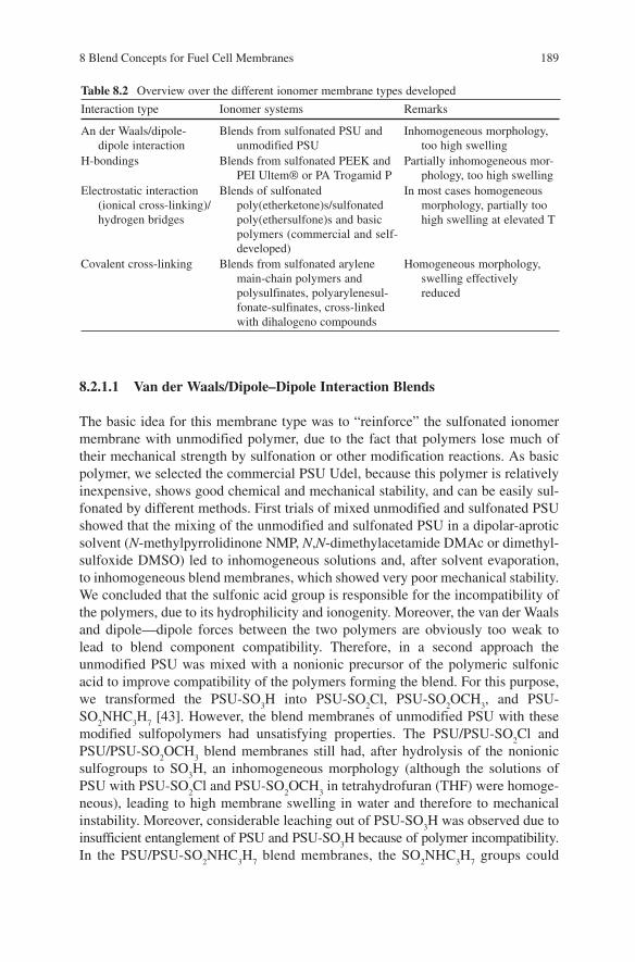
The water uptake of ionomer membranes can be reduced by introduction of spe-cific interactions (Fig. 8.1 ) between macromolecular chains.
In polymers different types of interactions are always present simultaneously. For example, van der Waals interactions between macromolecules are present in every polymer, and electrostatic interactions are always connected with hydrogen bonding and dipole — dipole interactions. In any event, introduction of chemical bonds between the macromolecules has the strongest impact on the polymer
188 J. Kerres
structure, because covalent cross-links are “ fixing ” the polymer morphology, while physical interactions between the macromolecules can be detached, e.g., hydrogen bondings can be dissociated by temperature increase.
8.2.1 Interaction-Blend Membrane Types
Ionomer membrane types have been developed that show the different types of interaction forces between the blend components. In Table 8.2 , an overview is given of the different ionomer membrane types developed. In the following, the devel-oped (blend) membrane types are described in more detail.
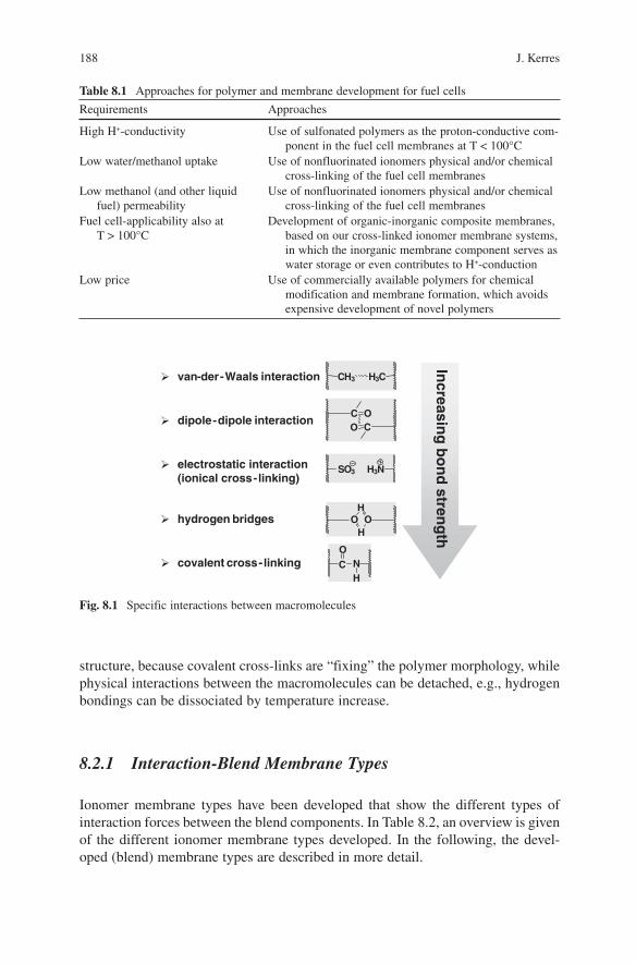
Table 8.1 Approaches for polymer and membrane development for fuel cells
Requirements Approaches
High H + -conductivity Use of sulfonated polymers as the proton-conductive com-ponent in the fuel cell membranes at T < 100 ° C
Low water/methanol uptake Use of nonfluorinated ionomers physical and/or chemical cross-linking of the fuel cell membranes
Low methanol (and other liquid fuel) permeability
Use of nonfluorinated ionomers physical and/or chemical cross-linking of the fuel cell membranes
Fuel cell-applicability also at T > 100 ° C
Development of organic-inorganic composite membranes, based on our cross-linked ionomer membrane systems, in which the inorganic membrane component serves as water storage or even contributes to H + -conduction
Low price Use of commercially available polymers for chemical modification and membrane formation, which avoids expensive development of novel polymers
Fig. 8.1 Specific interactions between macromolecules
van-der-Waals interaction
dipole-dipole interaction
electrostatic interaction(ionical cross-linking)
hydrogen bridges
covalent cross-linking
CH3 H3C
C OCO
SO3 H3N
OH
OH
C
ONH
Increasin
gb
on
dstren
gth
8 Blend Concepts for Fuel Cell Membranes 189
8.2.1.1 Van der Waals/Dipole – Dipole Interaction Blends
The basic idea for this membrane type was to “ reinforce ” the sulfonated ionomer membrane with unmodified polymer, due to the fact that polymers lose much of their mechanical strength by sulfonation or other modification reactions. As basic polymer, we selected the commercial PSU Udel, because this polymer is relatively inexpensive, shows good chemical and mechanical stability, and can be easily sul-fonated by different methods. First trials of mixed unmodified and sulfonated PSU showed that the mixing of the unmodified and sulfonated PSU in a dipolar-aprotic solvent ( N -methylpyrrolidinone NMP, N , N -dimethylacetamide DMAc or dimethyl-sulfoxide DMSO) led to inhomogeneous solutions and, after solvent evaporation, to inhomogeneous blend membranes, which showed very poor mechanical stability. We concluded that the sulfonic acid group is responsible for the incompatibility of the polymers, due to its hydrophilicity and ionogenity. Moreover, the van der Waals and dipole — dipole forces between the two polymers are obviously too weak to lead to blend component compatibility. Therefore, in a second approach the unmodified PSU was mixed with a nonionic precursor of the polymeric sulfonic acid to improve compatibility of the polymers forming the blend. For this purpose, we transformed the PSU-SO
3 H into PSU-SO
2 Cl, PSU-SO
2 OCH
3 , and PSU-
SO 2 NHC
3 H
7 [43] . However, the blend membranes of unmodified PSU with these
modified sulfopolymers had unsatisfying properties. The PSU/PSU-SO 2 Cl and
PSU/PSU-SO 2 OCH
3 blend membranes still had, after hydrolysis of the nonionic
sulfogroups to SO 3 H, an inhomogeneous morphology (although the solutions of
PSU with PSU-SO 2 Cl and PSU-SO
2 OCH
3 in tetrahydrofuran (THF) were homoge-
neous), leading to high membrane swelling in water and therefore to mechanical instability. Moreover, considerable leaching out of PSU-SO
3 H was observed due to
insufficient entanglement of PSU and PSU-SO 3 H because of polymer incompatibility.
In the PSU/PSU-SO 2 NHC
3 H
7 blend membranes, the SO
2 NHC
3 H
7 groups could
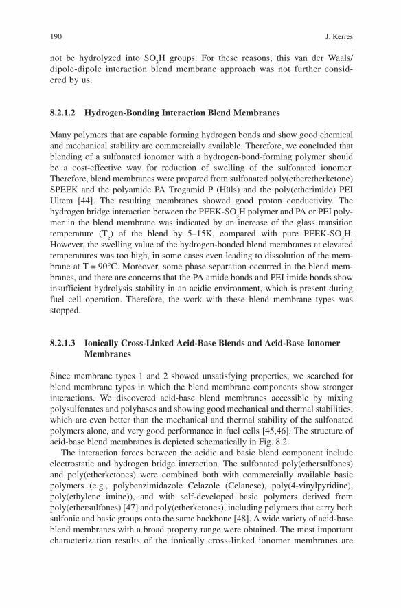
Table 8.2 Overview over the different ionomer membrane types developed
Interaction type Ionomer systems Remarks
An der Waals/dipole-dipole interaction
Blends from sulfonated PSU and unmodified PSU
Inhomogeneous morphology, too high swelling
H-bondings Blends from sulfonated PEEK and PEI Ultem ® or PA Trogamid P
Partially inhomogeneous mor-phology, too high swelling
Electrostatic interaction (ionical cross-linking)/hydrogen bridges
Blends of sulfonated poly(etherketone)s/sulfonated poly(ethersulfone)s and basic polymers (commercial and self-developed)
In most cases homogeneous morphology, partially too high swelling at elevated T
Covalent cross-linking Blends from sulfonated arylene main-chain polymers and polysulfinates, polyarylenesul-fonate-sulfinates, cross-linked with dihalogeno compounds
Homogeneous morphology, swelling effectively reduced
190 J. Kerres
not be hydrolyzed into SO 3 H groups. For these reasons, this van der Waals/
dipole-dipole interaction blend membrane approach was not further consid-ered by us.
8.2.1.2 Hydrogen-Bonding Interaction Blend Membranes
Many polymers that are capable forming hydrogen bonds and show good chemical and mechanical stability are commercially available. Therefore, we concluded that blending of a sulfonated ionomer with a hydrogen-bond-forming polymer should be a cost-effective way for reduction of swelling of the sulfonated ionomer. Therefore, blend membranes were prepared from sulfonated poly(etheretherketone) SPEEK and the polyamide PA Trogamid P (H ü ls) and the poly(etherimide) PEI Ultem [44] . The resulting membranes showed good proton conductivity. The hydrogen bridge interaction between the PEEK-SO
3 H polymer and PA or PEI poly-
mer in the blend membrane was indicated by an increase of the glass transition temperature (T
g ) of the blend by 5 – 15K, compared with pure PEEK-SO
3 H.
However, the swelling value of the hydrogen-bonded blend membranes at elevated temperatures was too high, in some cases even leading to dissolution of the mem-brane at T = 90 ° C. Moreover, some phase separation occurred in the blend mem-branes, and there are concerns that the PA amide bonds and PEI imide bonds show insufficient hydrolysis stability in an acidic environment, which is present during fuel cell operation. Therefore, the work with these blend membrane types was stopped.
8.2.1.3 Ionically Cross-Linked Acid-Base Blends and Acid-Base Ionomer Membranes
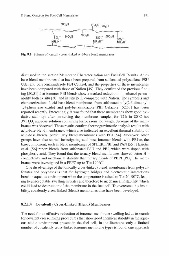
Since membrane types 1 and 2 showed unsatisfying properties, we searched for blend membrane types in which the blend membrane components show stronger interactions. We discovered acid-base blend membranes accessible by mixing polysulfonates and polybases and showing good mechanical and thermal stabilities, which are even better than the mechanical and thermal stability of the sulfonated polymers alone, and very good performance in fuel cells [45 , 46] . The structure of acid-base blend membranes is depicted schematically in Fig. 8.2 .
The interaction forces between the acidic and basic blend component include electrostatic and hydrogen bridge interaction. The sulfonated poly(ethersulfones) and poly(etherketones) were combined both with commercially available basic polymers (e.g., polybenzimidazole Celazole (Celanese), poly(4-vinylpyridine), poly(ethylene imine)), and with self-developed basic polymers derived from poly(ethersulfones) [47] and poly(etherketones), including polymers that carry both sulfonic and basic groups onto the same backbone [48] . A wide variety of acid-base blend membranes with a broad property range were obtained. The most important characterization results of the ionically cross-linked ionomer membranes are
8 Blend Concepts for Fuel Cell Membranes 191
discussed in the section Membrane Characterization and Fuel Cell Results. Acid-base blend membranes also have been prepared from sulfonated polysulfone PSU Udel and polybenzimidazole PBI Celazol, and the properties of these membranes have been compared with those of Nafion [49] . They confirmed the previous find-ing [50 , 51] that ionomer-PBI blends show a marked reduction in methanol perme-ability both ex situ [50] and in situ [51] , compared with Nafion. The synthesis and characterization of acid-base blend membranes from sulfonated poly(2,6-dimethyl-1,4-phenylene oxide) and polybenzimidazole PBI Celazole [52 , 53] has been reported recently. Interestingly, it was found that these membranes show good oxi-dative stability: after immersing the membrane samples for 72 h in 80 ° C hot 3%H
2 O
2 aqueous solution containing ferrous ions, no weight decrease of the mem-
branes was observed. These results confirm thermogravimetric analysis results with acid-base blend membranes, which also indicated an excellent thermal stability of acid-base blends, particularly blend membranes with PBI [54] . Moreover, other groups have also started investigating acid-base ionomer blends with PBI as the base component, such as blend membranes of SPEEK, PBI, and PAN [55] . Hasiotis et al. [56] report blends from sulfonated PSU and PBI, which were doped with phosphoric acid. They found that the ternary blend membranes showed better H + -conductivity and mechanical stability than binary blends of PBI/H
3 PO
4 . The mem-
branes were investigated in a PEFC up to T = 190 ° C. One disadvantage of the ionically cross-linked (blend) membranes from polysul-
fonates and polybases is that the hydrogen bridges and electrostatic interactions break in aqueous environment when the temperature is raised to T > 70 – 90 ° C, lead-ing to unacceptable swelling in water and therefore to mechanical instability, which could lead to destruction of the membrane in the fuel cell. To overcome this insta-bility, covalently cross-linked (blend) membranes also have been developed.
8.2.1.4 Covalently Cross-Linked (Blend) Membranes
The need for an effective reduction of ionomer membrane swelling led us to search for covalent cross-linking procedures that show good chemical stability in the aque-ous acidic environment present in the fuel cell. In the literature, only a limited number of covalently cross-linked ionomer membrane types is found, one approach
Fig. 8.2 Scheme of ionically cross-linked acid-base blend membranes
SO3-
SO3H
SO3H
SO3H
HO3S
HO3S
SO3- SO3H
SO3-
NR2H+NR2H+NR2H+
192 J. Kerres
being developed by Nolte et al. [57] , who covalently cross-linked a partially N-imidazolized sulfonated PES Victrex ionomer with 4,4 ′ -diaminodiphenylsulfone. However, there are strong concerns whether the sulfonamide bonds are sufficiently stable in the strongly acidic environment of a fuel cell. In a very recent paper of Mikhailenko et al. a novel cross-linking procedure for sulfonated poly(etherketone) is described, involving reaction of the sulfonic acid groups of polyetheretherketone with oligoalcohols such as ethylene glycol, glycerine, and meso erythrite under condensation (ester formation) [58] . However, the stability of these covalently cross-linked membrane systems in acidic environment was not investigated. Some years ago, we have discovered a novel cross-linking process in which sulfinate groups SO
2Me(Me = Li, Na...) are involved. It consists of a nucleophilic substitu-
tion (S-alkylation) of the sulfinate group with di- or oligohalogenealkanes or – arylenes [59] :
Polymer - SO2 Li + Hal - R - Hal + LiO
2 S - Polymer ® Polymer - S(O)
2 - R - S(O)
2
- Polymer Preferred halogen alkanes were α , ω -dibromo- or α , ω -diiodoalkanes Br(I)-(CH
2 )
x -Br(I) with x = 3 – 12, preferred dihalogenoarylenes were
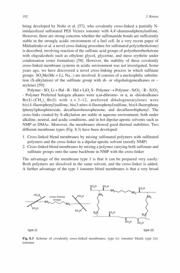
bis(4-fluorophenyl)sulfone, bis(3-nitro-4-fluorophenyl)sulfone, bis(4-fluorophenylphenyl)phosphinoxide, decafluorobenzophenone, and decafluorobiphenyl. The cross-links created by S-alkylation are stable in aqueous environment, both under alkaline, neutral, and acidic conditions, and in hot dipolar-aprotic solvents such as NMP or DMAc. Moreover, the membranes showed good thermal stabilities. Two different membrane types (Fig. 8.3 ) have been developed:
1. Cross-linked blend membranes by mixing sulfonated polymers with sulfinated polymers and the cross-linker in a dipolar-aprotic solvent (mostly NMP)
2. Cross-linked blend membranes by mixing a polymer carrying both sulfonate and sulfinate groups onto the same backbone in NMP with the cross-linker
The advantage of the membrane type 1 is that it can be prepared very easily: Both polymers are dissolved in the same solvent, and the cross-linker is added. A further advantage of the type 1 ionomer blend membranes is that a very broad
Fig. 8.3 Scheme of covalently cross-linked membranes; type (i): ionomer blend; type (ii): ionomer
SO2 SO2
HO3S
SO3H
HO3S
SO3H
cross-linkingbridge
SO2 SO2SO2
SO3HSO3HSO3H
SO2
O2SO2S
SO3H
SO3H SO3H
type (i) type (ii)
8 Blend Concepts for Fuel Cell Membranes 193
property range can be obtained by variation of the mass relation of the sulfinated and sulfonated blend component, the ion exchange capacity of both blend compo-nents, the backbone type of the blend components, and the cross-linker (different chain length of the cross-linkers, use of aliphatic or aromatic cross-linkers, use of mixtures of cross-linkers, etc.). The disadvantage of this type is that the polysul-fonate macromolecules can diffuse out of the blend membrane, because they are only entangled in the covalent network built up by the sulfinated polymer and cross-linker. However, this problem can be minimized by increasing the cross-link-ing density of the network. The advantage of the membrane type (2) is that all macromolecules are taking part in the network; therefore, no bleeding-out of the sulfonated component can take place. The disadvantage is that the effort for prepa-ration of mixed sulfonated/sulfinated polymers is higher than that for the prepara-tion of 100% sulfonated or 100% sulfinated polymers. The preparation of the starting polymers for the cross-linked membranes is described in the section Polymer Modification for Blend Membranes, and principal characterization results of a selection of the covalently cross-linked membranes are given in the section Membrane Characterization and Fuel Cell Results.
8.2.1.5 Covalent-Ionically Cross-Linked (Blend) Membranes
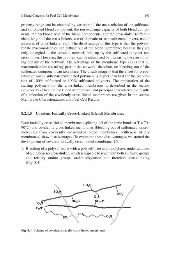
Both ionically cross-linked membranes (splitting-off of the ionic bonds at T = 70 – 90 ° C) and covalently cross-linked membranes (bleeding-out of sulfonated macro-molecules from covalently cross-linked blend membranes, brittleness of dry membranes) show disadvantages. To overcome these disadvantages, we started the development of covalent-ionically cross-linked membranes [60] :
1. Blending of a polysulfonate with a polysulfinate and a polybase, under addition of a dihalogeno cross-linker, which is capable to react with both sulfinate groups and tertiary amino groups under alkylation and therefore cross-linking (Fig. 8.4 )
Fig. 8.4 Scheme of covalent-ionically cross-linked membranes
HO3S
HO3S
SO3-
-O3S
-O3S
SO2SO2
R2N+
NR2H+
O2S
SO3H
194 J. Kerres
2. Blending of a polymer carrying both tertiary amino and sulfinate groups with a polysulfonate under addition of a dihalogeno cross-linker that alkylates both sulfinate and tertiary amino groups
3. Blending of a polymer carrying both sulfinate and sulfonate groups with a poly-base under addition of a dihalogeno cross-linker
We found that the disadvantage of the membrane type 1 is incompatibility between the polysulfinate and polyamine, leading to phase-separated membranes that show unsatisfying mechanical stability and insufficient suppressing of water uptake at elevated temperatures. Although not yet clear, it may be speculated that the incom-patibility of sulfinate and base polymers is due to the repulsion of the base group lone electron pair and the sulfinate group lone electron pair. This disadvantage of type 1 can be avoided with the type 2 membrane, in which the incompatible functional groups are bound to the same backbone in statistical distribution, and with type 3 membranes, in which the repulsion of the basic polymer with the sulfinate groups of the second polymer can be balanced by hydrogen bridges and/or dipole — dipole interaction of the base groups with the sulfonate groups of the second polymer. The membrane types 2 and 3 are transparent to visible light, indicating a homogeneous membrane morphology. One could also think of preparation of a polymer carrying sulfonate groups as well as sulfinate groups and basic groups onto the same back-bone, e.g., by reaction of a lithiated polymer with the three electrophiles SO
2 (for
sulfinate groups), SO 2 Cl
2 (for sulfochloride → sulfonic acid groups), and an aro-
matic carbonyl base (for basic groups). This polymer would inherently form a morphologically homogeneous membrane. However, such a polymer would be very expensive due to the need for careful dosage of the electrophile mixture, possible reaction between the different electrophiles, and reaction at low tempera-tures and under protective atmosphere, so that it probably would not be suitable for mass production.
8.2.1.6 Composite Blend Membranes
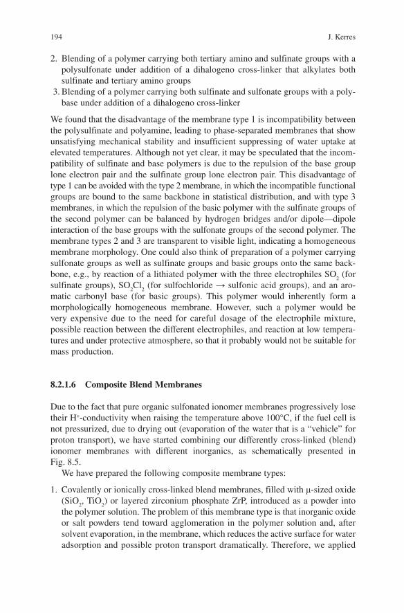
Due to the fact that pure organic sulfonated ionomer membranes progressively lose their H + -conductivity when raising the temperature above 100 ° C, if the fuel cell is not pressurized, due to drying out (evaporation of the water that is a “ vehicle ” for proton transport), we have started combining our differently cross-linked (blend) ionomer membranes with different inorganics, as schematically presented in Fig. 8.5 .
We have prepared the following composite membrane types:
1. Covalently or ionically cross-linked blend membranes, filled with µ -sized oxide (SiO
2 , TiO
2 ) or layered zirconium phosphate ZrP, introduced as a powder into
the polymer solution. The problem of this membrane type is that inorganic oxide or salt powders tend toward agglomeration in the polymer solution and, after solvent evaporation, in the membrane, which reduces the active surface for water adsorption and possible proton transport dramatically. Therefore, we applied
8 Blend Concepts for Fuel Cell Membranes 195
literature-known procedures for formation of in-membrane nanoparticles to our membrane types (particularly, Jones, Rozi è re, Bauer et al. performed pioneering work in this field) [61 – 65] .
2. Covalently or ionically cross-linked blend membranes, filled with layered ZrP by ion-exchange precipitation:
(a) Ion-exchange of the SO 3 H form of the membranes in a ZrOCl
2 solution to
yield the membranes in the (SO 3 )
2 ZrO-form
(b) Immersion of the ion-exchanged membranes in H 3 PO
4 ; during immersion,
the H 3 PO
4 diffuses into the membrane, and by reaction with the ZrO 2+ ions,
the layered ZrP is precipitating in the membrane matrix
3. Ionically cross-linked blend membranes from sulfonated poly(etherketone)s, PBI, and the heteropolyacid tungstenic phosphoric acid (TPA): Heteropolyacids (HPA) are strong Broenstedt acids [66] , and are interesting candidates for blending with ionomer membranes to increase their H + -conductivity. However, HPAs are water-soluble, which leads to concerns that they diffuse out of the ionomer membranes with time, and different authors have reported that indeed partial leaching-out of the HPAs from the membrane takes place [30] . A marked reduction of the leaching-out rate of the HPA molecules could be realized by synthesis of novel HPAs, as reported by Ponce et al. [31] . Our motivation for this develop-ment of ionomer-HPA blend membranes was to answer the question whether the ionical cross-links in ionically cross-linked blend membranes and resulting interactions between HPA molecules and ionomer blend membrane components (ionical cross-linking, H bridges, dipole – dipole interaction) could prevent leaching-out of the HPA.
Fig. 8.5 ICVT strategies for ionomer composite membranes
Covalently cross-linked
membranes
Covalent-ionicallycross-linkedmembranes
Ionicallycross-linkedmembranes
µ-/nano-sizedpowdersporous/nonporous
oxideshydroxidessalts(H+-conductive)
Heteropolyacidsphosphotungsticacid (PTA)other HPAs
Nano-sizedparticlesvia sol-gel(in-membrane)
oxideshydroxidessalts(H+-conductive)
Nano-sizedparticlesvia ion-exchange-precipitation(in-membrane)
oxideshydroxidessalts (H+-cond.)
196 J. Kerres
8.2.2 Polymer Modification for Blend Membranes
8.2.2.1 Synthesis of Sulfonated Polymers
For the synthesis of sulfonated poly(etherketones), well-known procedures were applied that involve sulfonation in 96% sulfonic acid [12 , 67] or oleum [14 , 68] . For the synthesis of sulfochlorinated poly(etherketone)s, the method described in [12] was used. PSU Udel and PPSU Radel R were sulfonated with n -butyllithium, as first described by Guiver [69] . The procedure involves reaction of the lithiated poly(ethersulfone) with SO
2 , yielding PSU/PPSU-sulfinate, followed by oxidation
with NaOCl to the PSU-sulfonate [11] , or reaction of the lithiated poly(ethersulfone) with SO
2 Cl
2 , yielding PSU-SO
2 Cl [70] , followed by hydrolysis to the PSU/PPSU
sulfonic acid.
8.2.2.2 Synthesis of the Sulfinated Polymers
For the synthesis of the PSU/PPSU-sulfinates, the discussed reaction of lithiated polymers with SO
2 was used. For the synthesis of poly(ethersulfones) carrying both
sulfinate and sulfonate groups, we partially oxidized the PSU/PPSU-sulfinates with subportions of NaOCl [71] . Poly(etheretherketone sulfinates) were prepared by reduction of poly(etheretherketone sulfochlorides) with aqueous Na
2 SO
3 [72] .
8.2.2.3 Synthesis of Basic Polymers
Amino groups were introduced into poly(ethersulfone)s by the following methods:
1. Introduction of the NH 2 group ortho to the sulfone bridge of the poly(ethersulfone)
was performed via a method developed by Guiver et al. [73 , 74] . The poly(ether sulfone amine) was then stepwise alkylated to the secondary and the tertiary polymeric amine by sequential addition of n -BuLi and CH
3 I [43] .
2. Introduction of the NH 2 group ortho to the ether bridge of poly(ethersulfone)s
or ortho to the ether bridge of poly(etheretherketone) was done according to [75 , 76] . The poly(ethersulfone) primary amines were then alkylated to the secondary amines by deprotonation with LDA, followed by alkylation with CH
3 I. The poly(ethersulfone) secondary amines were alkylated to the tertiary
amines by reaction with KOH/CH 3 I in DMSO. The poly(etheretherketone)
primary amines were alkylated to the tertiary amines by reaction with KOH/CH
3 I in one step.
3. Poly(ethersulfone)s were modified with tertiary amines by reaction of their lithiated form with basic aromatic aldehydes and ketones [47 , 77 , 78] .
4. Poly(ethersulfones) were modified with tertiary amines also by reaction of their lithiated species with basic aromatic carboxylic acid esters, as shown in [47] .
8 Blend Concepts for Fuel Cell Membranes 197
Interestingly, the created keto bridges of the product polymers are not attacked by residual PSU-Li sites to cross-link the polymer [47 , 77] .
8.2.2.4 Synthesis of Polymers Containing Both Basic and Sulfinate Groups
Poly(ethersulfone)s carrying both sulfinate and basic groups were prepared starting from lithiated poly(ethersulfone) [60 , 79 , 80] .
8.2.2.5 Synthesis of Polymers Containing Both Basic and Sulfonate Groups
Poly(etheretherketone) carrying both primary amino and sulfonate groups was pre-pared by nitration-reduction procedure [48] .
8.2.3 Membrane Characterization and Fuel Cell Results
We review here the dependence of the most important characterization and fuel cell application results of the different membrane types we have developed in our lab on different parameters.
8.2.3.1 Ionically Cross-Linked Blend Membranes
1. Dependence of the membrane properties on size of the repeating unit of the polybase. To ensure complete ionical cross-linking, the repeating units of the acidic and basic blend component should have comparable size and density of functional groups. We compared the extent of formation of ionical cross-links using the same polymeric sulfonic acid (sulfonated PSU, ion-exchange capacity (IEC) = 1.6 mequiv. g − 1 ), and the two polybases polybenzimidazole (PBI, base capacity 6.5 mequiv.g − 1 ) and polyethylenimine (PEI, base capacity 23.2 mequiv.g − 1 ) [81] . When the calculated (from the molar relation acid-base) and experi-mentally obtained IECs of the two acid-base blend membranes were compared, we found that for the SPSU/PBI blends the calculated and experimental IECs were similar, whereas for the SPSU/PEI blends the experimental IECs were much higher than calculated. This led to the conclusion that of the SPSU/PEI blends, from the sterical point of view, it is not possible that every amino group finds its acidic counterpart, due to the extreme difference in functional group densities of SPSU and PEI, respectively. On the contrary, of the SPSU/PBI blends, functional group densities are not that strongly different, as is the case of the SPSU/PEI blends, allowing that every acidic group finds its basic coun-terpart, taking into account the excess in acidic groups in the SPSU/PBI blends and chain segment mobilities of the blend components.
198 J. Kerres
2. Dependence of the membrane properties from the base strength of the base. We investigated to what extent the strength of the polybase influences the percent-age of formation of acid/base cross-links. Calculated and experimental acid/base blend ion exchange capacities were compared using the relatively strong poly-bases PBI (calculated p
k a of its protonated form 5.6), poly(4-vinylpyridine)
(P4VP, calculated p k a of its protonated form 6), and PSU-ortho-ether-diamine
(POSAII, calculated p k a of its protonated form 4) with the IECs of acid-base
blends using the very weak polybase PSU-ortho-sulfone-diamine (POSAI, cal-culated p
k a of its protonated form – 1.5). The results showed very clearly that the
calculated and experimental IECs were very close to each other for the PBI, P4VP-, and POSAII-containing acid-base blends [54 , 75 , 81] , whereas the experi-mental IECs were much higher than the calculated ones for the POSAI acid-base blends [75 , 81] , assuming that at p
k a of the conjugated acids to the respective
bases of < 0 – 2 the formation of acid-base bonds, or, in other words, the protona-tion of the base groups is incomplete. Therefore, for an effective suppression of swelling by ionic cross-links, the chosen base should be strong enough to ensure complete protonation when forming acid-base blends. A very good polybase candidate on that score is PBI, due to its high base strength and excellent chemi-cal stability [82] .
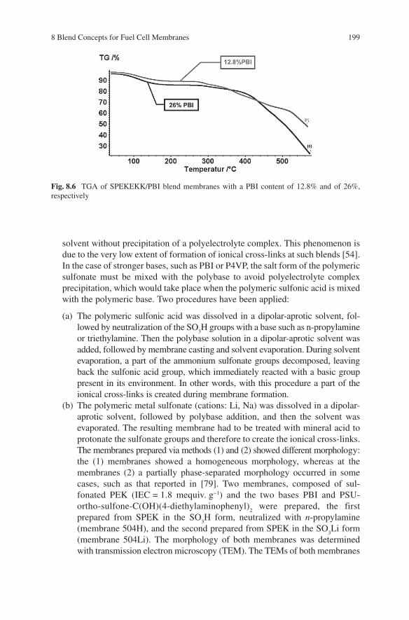
3. Dependence of the membrane properties from the ionical cross-linking density. We recently [68] compared the properties of membranes, composed of sul-fonated poly(etherketoneetherketoneketone) SPEKEKK Ultrapek and PBI, having the same IEC of 1.35 mequiv. SO
3 Hg − 1 , but different ionical cross-linking
densities. The different cross-linking density was obtained by use of sulfonated SPEKEKKs having different IECs ranging from 2.5 to 4.1 mequiv SO
3 Hg − 1 . As
expected, the water uptake of the membranes decreased with increasing cross-linking density: The membrane having the lowest cross-linking density in this series had a swelling value of 260% at 90 ° C, whereas the 90 ° C swelling degree of the membrane with the highest cross-linking density amounted to 90%. Interestingly, in the same membrane series an increase in electrical resistance with increasing cross-linking density was observed (membrane with the lowest cross-linking density: R
sp H+ =5 Ω cm; membrane with the highest cross-linking
density: R sp
H+ =11 Ω cm). An explanation for this finding could be that the ionic cross-links hinder the H + transport through the H + -conducting channels of the membranes by repulsion forces [68] . The thermal stability of all membranes up to ≈240 ° C from this series is comparable. In Fig. 8.6 , the TGA traces of the membranes with the highest and lowest cross-linking density in this series are shown. When the PBI portion of acid-base blend membranes, containing the same sulfonated polymer having the same IEC, is increased, a mass relation is reached in which the amount of acidic groups balance those of basic groups, in other words, where no excess free SO
3 H groups are available. Consequently,
such membranes are no longer H + conductive [54] . 4. Dependence of the membrane properties from the membrane preparation
method. In the case of very weak polybases, such as POSAI, it was possible to mix the polybase with the polymeric sulfonic acid in the same (dipolar-aprotic)
8 Blend Concepts for Fuel Cell Membranes 199
solvent without precipitation of a polyelectrolyte complex. This phenomenon is due to the very low extent of formation of ionical cross-links at such blends [54] . In the case of stronger bases, such as PBI or P4VP, the salt form of the polymeric sulfonate must be mixed with the polybase to avoid polyelectrolyte complex precipitation, which would take place when the polymeric sulfonic acid is mixed with the polymeric base. Two procedures have been applied:
(a) The polymeric sulfonic acid was dissolved in a dipolar-aprotic solvent, fol-lowed by neutralization of the SO
3 H groups with a base such as n -propylamine
or triethylamine. Then the polybase solution in a dipolar-aprotic solvent was added, followed by membrane casting and solvent evaporation. During solvent evaporation, a part of the ammonium sulfonate groups decomposed, leaving back the sulfonic acid group, which immediately reacted with a basic group present in its environment. In other words, with this procedure a part of the ionical cross-links is created during membrane formation.
(b) The polymeric metal sulfonate (cations: Li, Na) was dissolved in a dipolar-aprotic solvent, followed by polybase addition, and then the solvent was evaporated. The resulting membrane had to be treated with mineral acid to protonate the sulfonate groups and therefore to create the ionical cross-links. The membranes prepared via methods (1) and (2) showed different morphology: the (1) membranes showed a homogeneous morphology, whereas at the membranes (2) a partially phase-separated morphology occurred in some cases, such as that reported in [79] . Two membranes, composed of sul-fonated PEK (IEC = 1.8 mequiv. g − 1 ) and the two bases PBI and PSU-ortho-sulfone-C(OH)(4-diethylaminophenyl)
2 were prepared, the first
prepared from SPEK in the SO 3 H form, neutralized with n -propylamine
(membrane 504H), and the second prepared from SPEK in the SO 3 Li form
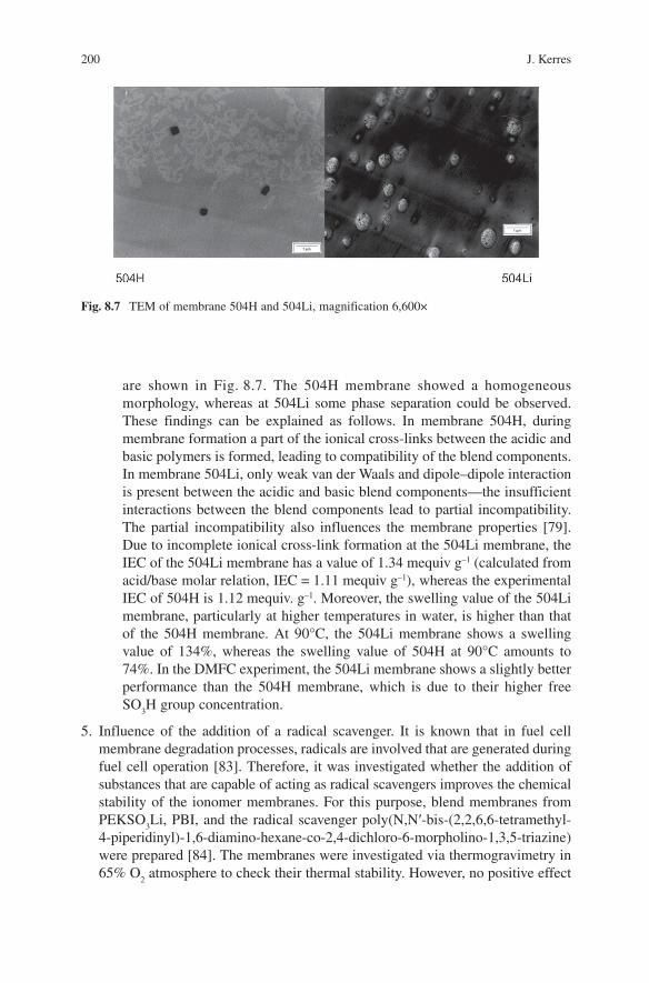
(membrane 504Li). The morphology of both membranes was determined with transmission electron microscopy (TEM). The TEMs of both membranes
Fig. 8.6 TGA of SPEKEKK/PBI blend membranes with a PBI content of 12.8% and of 26%, respectively
200 J. Kerres
are shown in Fig. 8.7 . The 504H membrane showed a homogeneous morphology, whereas at 504Li some phase separation could be observed. These findings can be explained as follows. In membrane 504H, during membrane formation a part of the ionical cross-links between the acidic and basic polymers is formed, leading to compatibility of the blend components. In membrane 504Li, only weak van der Waals and dipole–dipole interaction is present between the acidic and basic blend components — the insufficient interactions between the blend components lead to partial incompatibility. The partial incompatibility also influences the membrane properties [79] . Due to incomplete ionical cross-link formation at the 504Li membrane, the IEC of the 504Li membrane has a value of 1.34 mequiv g –1 (calculated from acid/base molar relation, IEC = 1.11 mequiv g –1 ), whereas the experimental IEC of 504H is 1.12 mequiv. g –1 . Moreover, the swelling value of the 504Li membrane, particularly at higher temperatures in water, is higher than that of the 504H membrane. At 90 ° C, the 504Li membrane shows a swelling value of 134%, whereas the swelling value of 504H at 90 ° C amounts to 74%. In the DMFC experiment, the 504Li membrane shows a slightly better performance than the 504H membrane, which is due to their higher free SO
3 H group concentration.
5. Influence of the addition of a radical scavenger. It is known that in fuel cell membrane degradation processes, radicals are involved that are generated during fuel cell operation [83] . Therefore, it was investigated whether the addition of substances that are capable of acting as radical scavengers improves the chemical stability of the ionomer membranes. For this purpose, blend membranes from PEKSO
3 Li, PBI, and the radical scavenger poly(N,N ′ -bis-(2,2,6,6-tetramethyl-
4-piperidinyl)-1,6-diamino-hexane-co-2,4-dichloro-6-morpholino-1,3,5-triazine) were prepared [84] . The membranes were investigated via thermogravimetry in 65% O
2 atmosphere to check their thermal stability. However, no positive effect
Fig. 8.7 TEM of membrane 504H and 504Li, magnification 6,600 ×
8 Blend Concepts for Fuel Cell Membranes 201
of the radical scavenger onto the thermal stability could be detected from TGA. All the membranes — SPEK/PBI/scavenger, SPEK/PBI, and SPEK/scavenger — had nearly identical thermal stabilities. For all three membranes, the splitting-off of the sulfonic acid group, which is the first step of membrane decomposition, started at around 230 ° C. The membrane decomposition process in the TGA was investigated by a TGA-FTIR coupling setup, which allows the FTIR-analysis of the TGA decomposition gases [84] . On the other hand, direct investigation of these membrane types in a fuel cell, placed in the resonator of an electron reso-nance spectrometer, showed very low radical concentration in the membranes, which is comparable to the radical concentration observed in Nafion membranes placed in the same setup [85] , suggesting good radical stability of these acid-base blend membranes.
6. Dependence of the DMFC performance on DMFC operation parameters. Different ternary acid-base blend membranes, composed of SPEK, PBI, and PSU-C(OH)(4-diethylaminophenyl)
2 , were tested in a DMFC up to temperatures
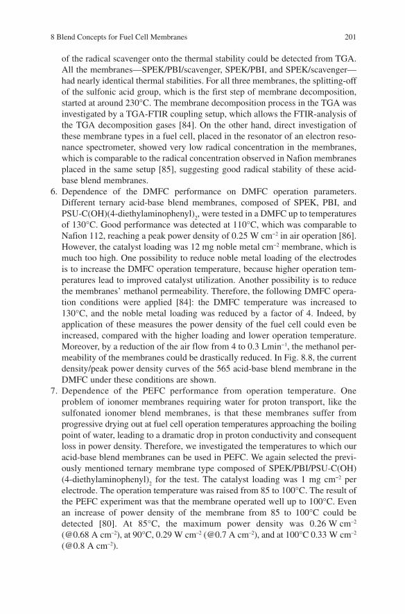
of 130 ° C. Good performance was detected at 110 ° C, which was comparable to Nafion 112, reaching a peak power density of 0.25 W cm − 2 in air operation [86] . However, the catalyst loading was 12 mg noble metal cm − 2 membrane, which is much too high. One possibility to reduce noble metal loading of the electrodes is to increase the DMFC operation temperature, because higher operation tem-peratures lead to improved catalyst utilization. Another possibility is to reduce the membranes’ methanol permeability. Therefore, the following DMFC opera-tion conditions were applied [84] : the DMFC temperature was increased to 130 ° C, and the noble metal loading was reduced by a factor of 4. Indeed, by application of these measures the power density of the fuel cell could even be increased, compared with the higher loading and lower operation temperature. Moreover, by a reduction of the air flow from 4 to 0.3 Lmin − 1 , the methanol per-meability of the membranes could be drastically reduced. In Fig. 8.8 , the current density/peak power density curves of the 565 acid-base blend membrane in the DMFC under these conditions are shown.
7. Dependence of the PEFC performance from operation temperature. One problem of ionomer membranes requiring water for proton transport, like the sulfonated ionomer blend membranes, is that these membranes suffer from progressive drying out at fuel cell operation temperatures approaching the boiling point of water, leading to a dramatic drop in proton conductivity and consequent loss in power density. Therefore, we investigated the temperatures to which our acid-base blend membranes can be used in PEFC. We again selected the previ-ously mentioned ternary membrane type composed of SPEK/PBI/PSU-C(OH)(4-diethylaminophenyl)
2 for the test. The catalyst loading was 1 mg cm − 2 per
electrode. The operation temperature was raised from 85 to 100 ° C. The result of the PEFC experiment was that the membrane operated well up to 100 ° C. Even an increase of power density of the membrane from 85 to 100 ° C could be detected [80] . At 85 ° C, the maximum power density was 0.26 W cm –2 (@0.68 A cm –2 ), at 90 ° C, 0.29 W cm –2 (@0.7 A cm –2 ), and at 100 ° C 0.33 W cm –2 (@0.8 A cm –2 ).
202 J. Kerres
8.2.3.2 Covalently Cross-Linked Blend Membranes
1. Dependence of the membrane properties from the type of cross-linker. It was investigated whether the use of an aromatic cross-linker for sulfinate-S-alkylation in blend membranes of sulfonated poly(etherketone)s with sulfinated poly(ethersulfones) leads to better thermal stability of the membrane. Therefore, blend membranes were prepared from sulfochlorinated poly(etherketone) SPEK (IEC = 3.5 mequiv. g –1 ), sulfinated PSU (1 group per RU), and cross-linkers 1,4-diiodobutane or bis(3-nitro-4-fluorophenyl)sulfone, respectively [87] . After hydrolysis of the SO
2 Cl groups to SO
3 H groups of the membranes, the following
results were obtained. The proton conductivity of the two membranes was nearly identical, the water uptake characteristics were similar, and the thermal stability of the two membranes was nearly the same. To summarize, the use of an aromatic cross-linker does not improve the thermal stability of the membranes.
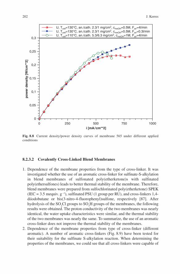
2. Dependence of the membrane properties from type of cross-linker (different aromatic). A number of aromatic cross-linkers (Fig. 8.9 ) have been tested for their suitability for the sulfinate S-alkylation reaction. When determining the properties of the membranes, we could see that all cross-linkers were capable of
0
0,05
0,1
0,15
0,2
0,25
0,3
po
wer
den
sity
[W/c
m**
2]
0 250 500 750 1000i [mA/cm**2]
U, Tcell=130°C, an./cath. 2.3/1 mg/cm2, cmeOH=0.5M, Fair=4l/minU, Tcell=130°C, an./cath. 2.3/1 mg/cm2, cmeOH=0.5M, Fair=0.3l/minU, Tcell=110°C, an./cath. 5.3/6.3 mg/cm2, cmeOH=1M, Fair=4l/min
Fig. 8.8 Current density/power density curves of membrane 565 under different applied conditions
8 Blend Concepts for Fuel Cell Membranes 203
S-alkylating the sulfinate groups of the blend membrane. The properties of all prepared membranes were comparable [87 , 88] , their specific resistance being in the range 8 – 12 cm, which is a value comparable to Nafion. Moreover, their swelling at elevated temperatures (90 ° C) was limited to 40 – 60%, which indicates a high degree of cross-linking. The cross-linking was also confirmed by extrac-tion experiments of the membranes in 90 ° C hot DMAc. The extraction residue was in good accordance with the mass share of the sulfinated and cross-linked blend membrane component. The thermal stability of all investigated blend membranes was in the same range.
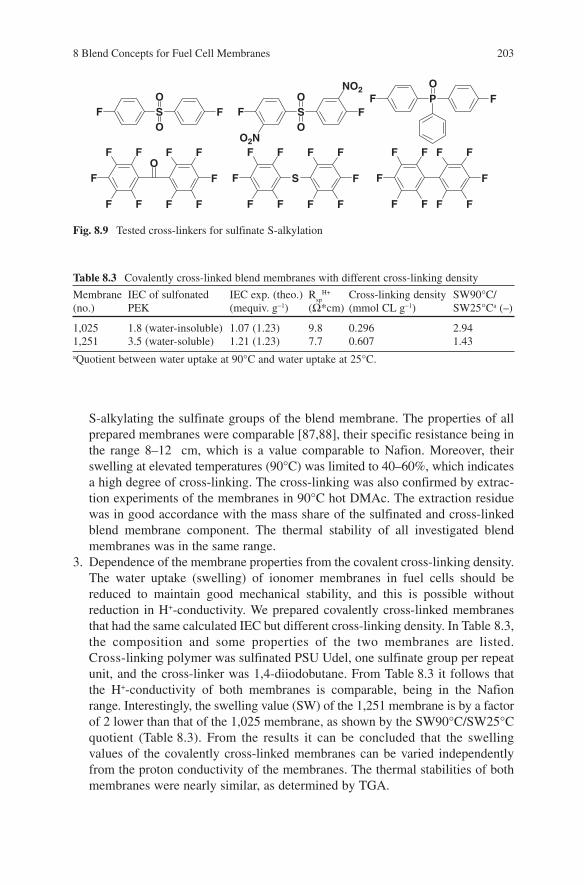
3. Dependence of the membrane properties from the covalent cross-linking density. The water uptake (swelling) of ionomer membranes in fuel cells should be reduced to maintain good mechanical stability, and this is possible without reduction in H + -conductivity. We prepared covalently cross-linked membranes that had the same calculated IEC but different cross-linking density. In Table 8.3 , the composition and some properties of the two membranes are listed. Cross-linking polymer was sulfinated PSU Udel, one sulfinate group per repeat unit, and the cross-linker was 1,4-diiodobutane. From Table 8.3 it follows that the H + -conductivity of both membranes is comparable, being in the Nafion range. Interestingly, the swelling value (SW) of the 1,251 membrane is by a factor of 2 lower than that of the 1,025 membrane, as shown by the SW90 ° C/SW25 ° C quotient (Table 8.3 ). From the results it can be concluded that the swelling values of the covalently cross-linked membranes can be varied independently from the proton conductivity of the membranes. The thermal stabilities of both membranes were nearly similar, as determined by TGA.
Fig. 8.9 Tested cross-linkers for sulfinate S-alkylation
SO
OFF S
O
OFF
NO2
O2N
PO
FF
OFF
FF
F F FF
F F
S FF
FF
F F FF
F F
F
FF
F F
F
FF
F F
Table 8.3 Covalently cross-linked blend membranes with different cross-linking density
Membrane (no.)
IEC of sulfonated PEK
IEC exp. (theo.) (mequiv. g − 1 )
R sp
H+ ( Ω *cm)
Cross-linking density (mmol CL g − 1 )
SW90 ° C/SW25 ° C a ( – )
1,025 1.8 (water-insoluble) 1.07 (1.23) 9.8 0.296 2.94 1,251 3.5 (water-soluble) 1.21 (1.23) 7.7 0.607 1.43
a Quotient between water uptake at 90 ° C and water uptake at 25 ° C.
204 J. Kerres
4. Dependence of the membrane properties from the type of sulfonated poly(etherketone). The three different sulfonated poly(etherketones) SPEK, SPEEK, and SPEKEKK have been used in covalently cross-linked blend membranes as the H+-conductive component. It was found that the properties of the different membranes were very close to one another [87] .
5. Dependence of the membrane properties from the type of sulfinated poly(ethersulfone). The two different poly(ethersulfones), PSU and PPSU, were used as the cross-linking component in the covalently cross-linked blend membranes. The membranes prepared from these polymers showed comparable properties. There are some indications that the thermal and mechanical stability of the membranes from sulfinated PPSU is slightly better than the thermal and mechanical stability of membranes using sulfinated PSU [88] .
6. Dependence of the membrane properties from membrane type (blend/not blend). Covalently cross-linked blend membranes such as those described herein have been compared with covalently cross-linked membranes prepared from sulfochlo-rinated PEEK, which has been partially reduced using Na
2 SO
3 to yield sulfonated-
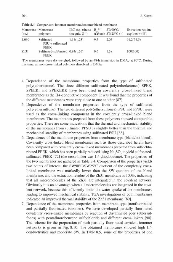
sulfinated PEEK [72] (the cross-linker was 1,4-diiodobutane). The properties of the two membranes are gathered in Table 8.4 . Comparison of the properties yields two points of interest: the SW90 ° C/SW25 ° C quotient of the completely cross-linked membrane was markedly lower than the SW quotient of the blend membrane, and the extraction residue of the Zh31 membrane is 100%, indicating that all macromolecules of the Zh31 are integrated in the covalent network. Obviously it is an advantage when all macromolecules are integrated in the cova-lent network, because this efficiently limits the water uptake of the membranes, leading to improved mechanical stability. TGA investigations of both membranes indicated an improved thermal stability of the Zh31 membrane [89] .
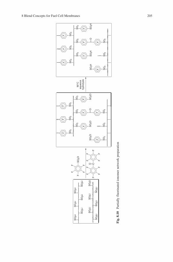
7. Dependence of the membrane properties from membrane type (nonfluorinated and partially fluorinated ionomer). We have developed partially fluorinated covalently cross-linked membranes by reaction of disulfinated poly (ethersul-fones) with pentafluorobenzene sulfochloride and different cross-linkers [90] . The scheme for the preparation of such partially fluorinated covalent ionomer networks is given in Fig. 8.10 . The obtained membranes showed high H + -conductivities and moderate SW. In Table 8.5 , some of the properties of one
Table 8.4 Comparison: ionomer membrane/ionomer blend membrane
Membrane (no.)
Membrane polymers
IEC exp. (theo.) (mequiv. G − 1 )
R sp
H+ ( Ω *cm)
SW90 ° C/SW25 ° C ( − )
Extraction residue exp(theo) a (%)
1,030 Sulfinated PSU + sulfonated PEEK
1.14(1.23) 9.5 2.05 91.2(54.5)
Zh31 Sulfinated-sulfonated PEEK
0.84(1.26) 9.6 1.38 100(100)
a The membranes were dry-weighed, followed by an 48-h immersion in DMAc at 90 ° C. During this time, all non-cross-linked polymers dissolved in DMAc.
8 Blend Concepts for Fuel Cell Membranes 205
Fig
. 8.1
0 Pa
rtia
lly f
luor
inat
ed io
nom
er n
etw
ork
prep
arat
ion
SO2L
i SO2L
iSO2L
i SO2L
iSO2L
i SO2L
iF
F FF
SO2C
l
F COF
F
F
FF
FF
F
FF
SO2L
i
SO2L
i
SO2L
i
SO2L
i
SO2L
i
SO2L
i
SO2
SO2
SO2
SO2
SO2
SO2
SO2C
lSO
2Cl
O
SO2
SO2
SO2
SO2C
l
90°C
aque
ous
hydr
olys
isF
F FF
F
FF
FF
FF
FF
F FF
SO2
SO2
SO2
SO2
SO2
SO2
SO3H
SO3H
O
SO2
SO2
SO2
SO3H
206 J. Kerres
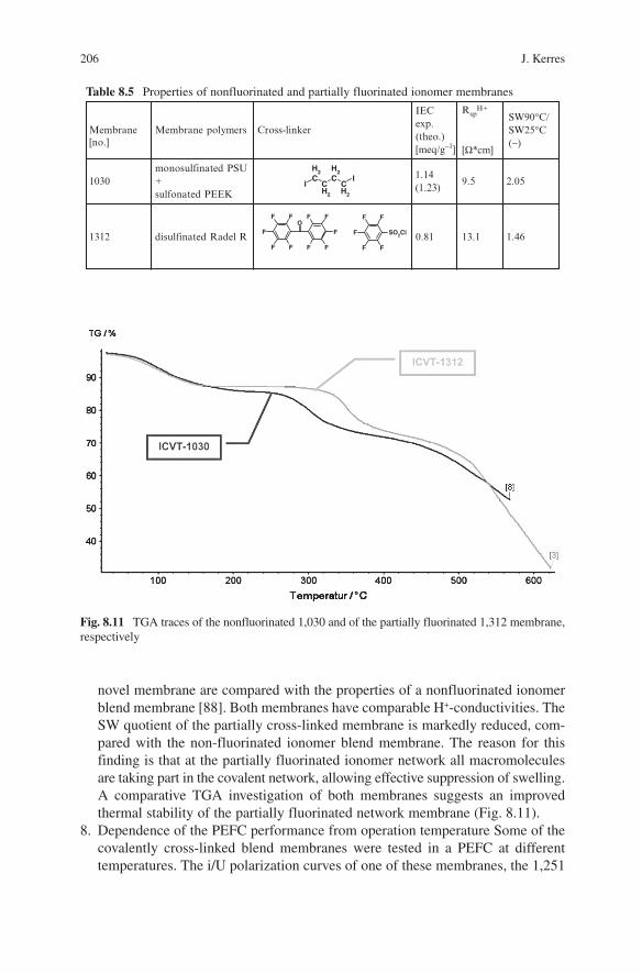
Fig. 8.11 TGA traces of the nonfluorinated 1,030 and of the partially fluorinated 1,312 membrane, respectively
Table 8.5 Properties of nonfluorinated and partially fluorinated ionomer membranes
ICH2
CH2
CH2
CH2
I
IEC exp. (theo.) [meq/g−1]
SW90°C/ SW25°C (−)
1030 monosulfinated PSU+ sulfonated PEEK
1.14 (1.23)
2.05
1312 disulfinated Radel R 0.81 1.46
OFF
FF
F F FF
F F
F
FF
F F
SO2Cl
RspH+
[Ω*cm]
9.5
13.1
Membrane[no.]
Membrane polymers Cross-linker
novel membrane are compared with the properties of a nonfluorinated ionomer blend membrane [88] . Both membranes have comparable H + -conductivities. The SW quotient of the partially cross-linked membrane is markedly reduced, com-pared with the non-fluorinated ionomer blend membrane. The reason for this finding is that at the partially fluorinated ionomer network all macromolecules are taking part in the covalent network, allowing effective suppression of swelling. A comparative TGA investigation of both membranes suggests an improved thermal stability of the partially fluorinated network membrane (Fig. 8.11 ).
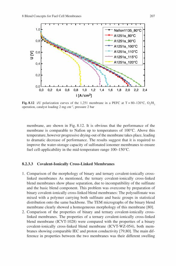
8. Dependence of the PEFC performance from operation temperature Some of the covalently cross-linked blend membranes were tested in a PEFC at different temperatures. The i/U polarization curves of one of these membranes, the 1,251
8 Blend Concepts for Fuel Cell Membranes 207
membrane, are shown in Fig. 8.12 . It is obvious that the performance of the membrane is comparable to Nafion up to temperatures of 100 ° C. Above this temperature, however progressive drying-out of the membrane takes place, leading to dramatic decrease of performance. The results suggest that it is required to improve the water-storage capacity of sulfonated ionomer membranes to ensure fuel cell-applicability in the mid-temperature range 100 – 150 ° C.
8.2.3.3 Covalent-Ionically Cross-Linked Membranes
1. Comparison of the morphology of binary and ternary covalent-ionically cross-linked membranes As mentioned, the ternary covalent-ionically cross-linked blend membranes show phase separation, due to incompatibility of the sulfinate and the basic blend component. This problem was overcome by preparation of binary covalent-ionically cross-linked blend membranes: The polysulfonate was mixed with a polymer carrying both sulfinate and basic groups in statistical distribution onto the same backbone. The TEM micrographs of the binary blend membrane clearly showed a homogeneous morphology of this membrane [80] .
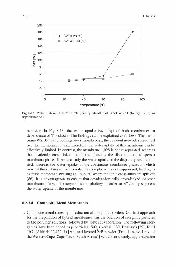
2. Comparison of the properties of binary and ternary covalent-ionically cross-linked membranes. The properties of a ternary covalent-ionically cross-linked blend membrane (ICVT-1028) were compared with the properties of a binary covalent-ionically cross-linked blend membrane (ICVT-WZ-054), both mem-branes showing comparable IEC and proton conductivity [79 , 80] . The main dif-ference in properties between the two membranes was their different swelling
Fig. 8.12 i/U polarization curves of the 1,251 membrane in a PEFC at T = 80 – 120 ° C, O 2 /H
2
operation, catalyst loading 2 mg cm − 2 , pressure 2 bar
0,0 0,2 0,4 0,6 0,8 1,0 1,2 1,4 1,6 1,8 2,0 2,2 2,4
0,2
0,0
0,4
0,6
0,8
1,0 Nafion1135_80°C
A1251a_80°C
A1251a_90°C
A1251a_100°C
A1251a_110°C
A1251a_115°C
A1251a_120°C
U [
V]
0,0 0,2 0,4 0,6 0,8 1,0 1,2 1,4 1,6 1,8 2,0 2,2 2,4
Nafion1135_80°C
A1251a_80°C
A1251a_90°C
A1251a_100°C
A1251a_110°C
A1251a_115°C
A1251a_120°C
Nafion1135_80°C
A1251a_80°C
A1251a_90°C
A1251a_100°C
A1251a_110°C
A1251a_115°C
A1251a_120°C
i [A / cm2]
208 J. Kerres
behavior. In Fig. 8.13 , the water uptake (swelling) of both membranes in dependence of T is shown. The findings can be explained as follows: The mem-brane WZ 054 has a homogeneous morphology, the covalent network spreads all over the membrane matrix. Therefore, the water uptake of this membrane can be effectively limited. In contrast, the membrane 1,028 is phase separated, whereas the covalently cross-linked membrane phase is the discontinuous (disperse) membrane phase. Therefore, only the water uptake of the disperse phase is lim-ited, whereas the water uptake of the continuous membrane phase, in which most of the sulfonated macromolecules are placed, is not suppressed, leading to extreme membrane swelling at T > 60 ° C where the ionic cross-links are split off [86] . It is advantageous to ensure that covalent-ionically cross-linked ionomer membranes show a homogeneous morphology in order to efficiently suppress the water uptake of the membranes.
8.2.3.4 Composite Blend Membranes
1. Composite membranes by introduction of inorganic powders. Our first approach for the preparation of hybrid membranes was the addition of inorganic particles to the polymer solutions, followed by solvent evaporation. The following inor-ganics have been added as µ -particles: SiO
2 (Aerosil 380, Degussa) [79] , Rutil
TiO 2 (Aldrich 22,422 – 7) [80] , and layered ZrP powder (Prof. Linkov, Univ. of
the Western Cape, Cape Town, South Africa) [89] . Unfortunately, agglomeration
Fig. 8.13 Water uptake of ICVT-1028 (ternary blend) and ICVT-WZ-54 (binary blend) in dependence of T
0
20
40
60
80
100
120
140
160
180
200
0 20 40 60 80 100
temperature [°C]
SW
[%
]SW 1028 [%]
SW WZ054 [%]
8 Blend Concepts for Fuel Cell Membranes 209
of the inorganic particles in the membrane matrix took place, leading to large inorganic particles within the membrane morphology that were not effective in adsorption of water, particularly at elevated temperatures of >80 ° C. When applied to DMFC, a strong reduction of MeOH permeability could be realized by addition of SiO
2 particles, but also the DMFC performance was reduced.
Consequently, the fuel cell performance of these membranes was not improved, compared with the pure organomembranes [80] .
2. Comparison of organo blend membranes with ZrP hybrid blend membranes. By the application of the ZrOCl
2 -H
3 PO
4 procedure to the covalently cross-linked
blend membranes, transparent hybrid membranes were obtained, indicating that the size of particles was well below the wavelength of visible light [88] . In Table 8.6 , some of the properties of a covalently cross-linked blend membrane (ICVT-1228) and ZrP hybrid membrane based onto this membrane (ICVT-1228ZrP) are listed. Interestingly, the room temperature proton conductivity of the composite membrane, compared with the organomembrane, is reduced by a factor of two. This finding can be explained by a stricture of the ion-conducting channels by the growth of the inorganic phase, which preferably takes place in the vicinity of the SO
3 H ion-aggregates. In Fig. 8.14 , TEM micrographs of the
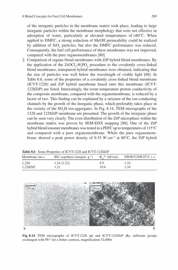
1228 and 1228ZrP membrane are presented. The growth of the inorganic phase can be seen very clearly. The even distribution of the ZrP microphase within the membrane matrix was proven by SEM-EDX mapping [88] . One of the ZrP hybrid blend ionomer membranes was tested in a PEFC up to temperatures of 115 ° C and compared with a pure organomembrane. While the pure organomem-brane showed a peak power density of 0.35 W cm − 2 at 80 ° C, the ZrP hybrid
Table 8.6 Some Properties of ICVT-1228 and ICVT-1228ZrP
Membrane (no.) IEC exp(theo) (mequiv. g − 1 ) R sp
H+ ( Ω *cm) SW90 ° C/SW25 ° C (–)
1,228 1.24 (1.23) 9.5 1.33 1,228ZrP 1,21 19.6 1.24
Fig. 8.14 TEM micrographs of ICVT-1228 (a) and ICVT-1228ZrP (b), sulfonate groups exchanged with Pb 2+ for a better contrast, magnification 52,000 ×

210 J. Kerres
membrane had a peak power density of 0.6 W cm − 2 at 115 ° C, indicating that the ZrP phase had a positive impact on PEFC performance. The improvement of PEFC performance by the ZrP phase could be due to both improvement of water storage ability and the contribution of the ZrP phase to the proton transport at elevated temperatures, as suggested in the literature [63 , 65 , 38] . However, further work has to be done for in-depth clarification of the influence of the ZrP phase to PEFC performance of the hybrid membranes.
3. Properties of composite membranes, repeatedly treated with ZrOCl 2 -H
3 PO
4 .
Blend membranes from sulfonated PEKEKK Ultrapek (IEC = 3 mequiv g − 1 ) and sulfinated PSU Udel (1 group per RU), cross-linked with 1,4-diiodobutane (ICVT-1202), were repeatedly treated with ZrOCl
2 -H
3 PO
4 . The change in mem-
brane properties with the number of treatments of the ICVT-1202 membrane was monitored. In Fig. 8.15 , the IEC and H + -conductivities of the membranes are presented. In Fig. 8.16 , the water uptake of the neat and the ZrOCl
2 -H
3 PO
4 –
Fig. 8.15 IEC and H + -conductivities of the 1,202 membranes
0
5
10
15
20
25
30IEC (direct) [meq/g]Rspecif. [Ohm*cm]
0,79 1,33 1,42 1,31
10 21,4 22,5 26,6
neat1st
treatment2nd
treatment3rd
treatment
Fig. 8.16 Water uptake of the 1,202 membranes in dependence of T
0
10
20
30
40
50
60
70
0 20 40 60 80 100T [°C]
wat
eru
pta
ke[%
]
neat
1st treatment
2nd treatment
3rd treatment
8 Blend Concepts for Fuel Cell Membranes 211
treated membranes are shown. From Figs. 8.15 and 8.16 , the following can be observed: by the ZrP treatment, the H + resistance is increased, supporting the hypothesis that the deposit of ZrP in the ion-conducting channels narrows them, leading to hindrance of H+-transport. Moreover, the water uptake is reduced, which can be explained with (hydrogen bridge, dipole – dipole) interactions between the ZrP phase, which contains Zr(HPO
4 )
2 groups [91] , and the SO
3 H
groups of the organo-ionomer. Repeated treatment of ionically cross-linked blend membranes with ZrOCl
2 /H
3 PO
4 lead to similar results: the H + -resistance
of the membranes was increased, and their water uptake was reduced [91] . 4. Properties of ionically cross-linked membranes containing tungstenic phos-
phoric acid. Blend membranes from sulfonated PEKEKK Ultrapek, PBI Celazole, and tungstenic phosphoric acid (TPA) were prepared [68] . Indeed, by introduction of TPA the proton conductivity of the membranes could be enhanced. We investigated the possible leaching out of HPA molecules from the membrane matrix by post-treatment of the pure organomembrane and the com-posite membranes, initially containing 10, 20, and 40 wt% TPA, in (a) 10%HCl at 90 ° C for 48 h and (b) water at 60 ° C for 48 h, followed by investigation of the posttreated membranes in TGA up to 600 ° C. TPA remains as a residual when the organic membrane part is thermally removed. The pure organo blend membrane was completely decomposed after TGA, whereas the TGA of the composite membranes showed that only a part of the HPA was present in the membrane after the post-treatment (Table 8.7 ). The interactions present in the SPEKEKK-PBI-TPA membranes are not strong enough to prevent leaching out of the TPA ions, and methods must be found for immobilization of the heteropolyacids in the ionomer blend membrane matrix, which could be achieved by generation of chemical bonds between the TPA molecules and the organomembrane.
8.2.4 Comparison of the Properties of the Different Ionomer Membrane Systems
To be able to assess the suitability of the differently cross-linked blend membrane types for the fuel cell application, we compared representative membranes of the different types having comparable calculated IEC with each other.
Table 8.7 TPA Loss in SPEKEKK-PBI-TPA membranes
Content TPA (%) Calc. residuals (dehydrated TPA) (%)
0 0 10 8.56 20 17.12 40 34.24 100 85.6
212 J. Kerres
8.2.4.1 Comparison of the Properties of Differently Cross-Linked Ionomer Membrane Types Having Comparable Calculated IEC
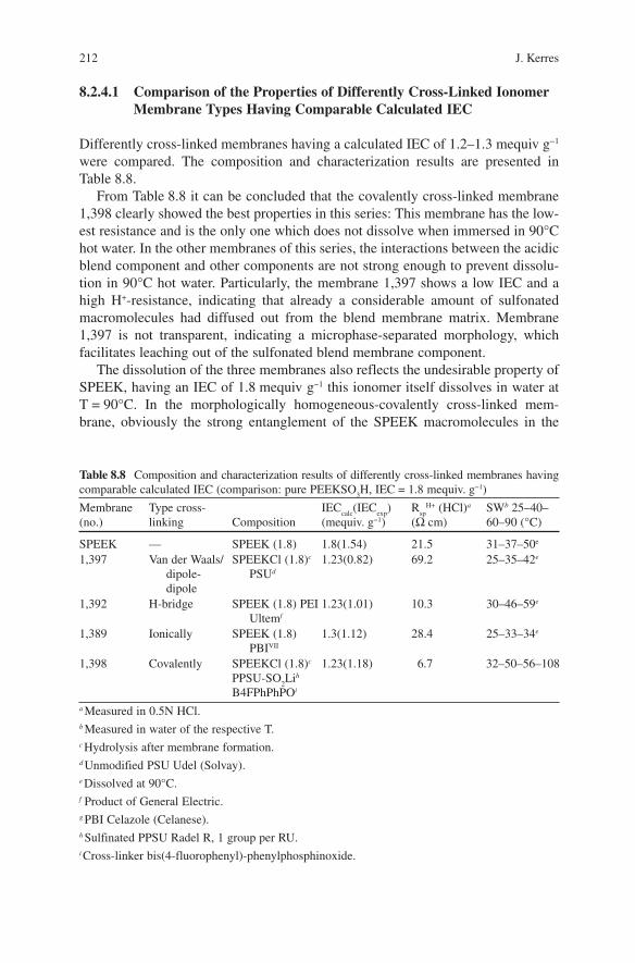
Differently cross-linked membranes having a calculated IEC of 1.2 – 1.3 mequiv g − 1 were compared. The composition and characterization results are presented in Table 8.8 .
From Table 8.8 it can be concluded that the covalently cross-linked membrane 1,398 clearly showed the best properties in this series: This membrane has the low-est resistance and is the only one which does not dissolve when immersed in 90 ° C hot water. In the other membranes of this series, the interactions between the acidic blend component and other components are not strong enough to prevent dissolu-tion in 90 ° C hot water. Particularly, the membrane 1,397 shows a low IEC and a high H + -resistance, indicating that already a considerable amount of sulfonated macromolecules had diffused out from the blend membrane matrix. Membrane 1,397 is not transparent, indicating a microphase-separated morphology, which facilitates leaching out of the sulfonated blend membrane component.
The dissolution of the three membranes also reflects the undesirable property of SPEEK, having an IEC of 1.8 mequiv g − 1 this ionomer itself dissolves in water at T = 90 ° C. In the morphologically homogeneous-covalently cross-linked mem-brane, obviously the strong entanglement of the SPEEK macromolecules in the
Table 8.8 Composition and characterization results of differently cross-linked membranes having comparable calculated IEC (comparison: pure PEEKSO
3 H, IEC = 1.8 mequiv. g − 1 )
Membrane (no.)
Type cross-linking Composition
IEC calc
(IEC exp
) (mequiv. g − 1 )
R sp
H+ (HCl) a ( Ω cm)
SW b 25 – 40 – 60 – 90 ( ° C)
SPEEK — SPEEK (1.8) 1.8(1.54) 21.5 31 – 37 – 50 e 1,397 Van der Waals/
dipole-dipole
SPEEKCl (1.8) c PSU d
1.23(0.82) 69.2 25 – 35 – 42 e
1,392 H-bridge SPEEK (1.8) PEI Ultem f
1.23(1.01) 10.3 30 – 46 – 59 e
1,389 Ionically SPEEK (1.8) PBI VII
1.3(1.12) 28.4 25 – 33 – 34 e
1,398 Covalently SPEEKCl (1.8) c PPSU-SO
2 Li h
B4FPhPhPO i
1.23(1.18) 6.7 32 – 50 – 56 – 108
a Measured in 0.5N HCl.
b Measured in water of the respective T.
c Hydrolysis after membrane formation.
d Unmodified PSU Udel (Solvay).
e Dissolved at 90 ° C.
f Product of General Electric.
g PBI Celazole (Celanese).
h Sulfinated PPSU Radel R, 1 group per RU.
i Cross-linker bis(4-fluorophenyl)-phenylphosphinoxide.
8 Blend Concepts for Fuel Cell Membranes 213
covalent network prevents their leaching out. Interestingly, use of SPEK (IEC = 1.8 mequiv g − 1 ) instead of SPEEK (IEC = 1.8 mequiv g − 1 ) in ionically cross-linked membranes with PBI, having the same IEC as membrane 1,389, prevents dissolution in water at T = 90 ° C [84] . Obviously, in SPEK-PBI blends stronger interactions between the blend components are present than in SPEEK-PBI blends. The reason for this finding is not yet clear. However, due to the higher concentra-tion of carbonyl groups in SPEK, compared with SPEEK, one can speculate that the carbonyl group markedly contributes to the interaction between the macromo-lecular chains by dipole – dipole forces and H-bridges.
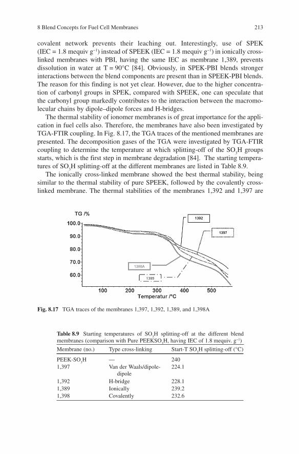
The thermal stability of ionomer membranes is of great importance for the appli-cation in fuel cells also. Therefore, the membranes have also been investigated by TGA-FTIR coupling. In Fig. 8.17 , the TGA traces of the mentioned membranes are presented. The decomposition gases of the TGA were investigated by TGA-FTIR coupling to determine the temperature at which splitting-off of the SO
3 H groups
starts, which is the first step in membrane degradation [84] . The starting tempera-tures of SO
3 H splitting-off at the different membranes are listed in Table 8.9 .
The ionically cross-linked membrane showed the best thermal stability, being similar to the thermal stability of pure SPEEK, followed by the covalently cross-linked membrane. The thermal stabilities of the membranes 1,392 and 1,397 are
Table 8.9 Starting temperatures of SO 3 H splitting-off at the different blend
membranes (comparison with Pure PEEKSO 3 H, having IEC of 1.8 mequiv. g − 1 )
Membrane (no.) Type cross-linking Start-T SO 3 H splitting-off ( ° C)
PEEK-SO 3 H — 240
1,397 Van der Waals/dipole-dipole
224.1
1,392 H-bridge 228.1 1,389 Ionically 239.2 1,398 Covalently 232.6
Fig. 8.17 TGA traces of the membranes 1,397, 1,392, 1,389, and 1,398A
214 J. Kerres
markedly worse. The reason for this finding is not yet clear. In the literature it is reported that in polymer blends in some cases one blend component facilitates the degradation of the other blend component, as was shown for PBI/polyarylate blends [92] . From the obtained results it can be concluded that the covalently and ionically cross-linked blend membrane are interesting candidates for fuel cell application.
8.2.4.2 Comparison of the Properties of Covalently, Ionically, and Covalent-Ionically Cross-Linked Ionomer Membranes Having the Same IEC
To find out which of the ionomer blend membranes are the most promising for the application in membrane fuel cells, if any, we prepared a covalently, covalent-ionically, and ionically cross-linked membrane having comparable IEC [86] . Membranes were obtained that showed nearly identical H + -conductivities and thermal stabilities. However, the membranes showed marked differences in swelling behavior: The covalently cross-linked membrane (ICVT-1025) had a water uptake value of 87% at 90 ° C, whereas the water uptake value of the ionically cross-linked membrane (ICVT-1029) amounted to 190%, and that of the covalent-ionically cross-linked membrane (ICVT-1028) was 181%. As pointed out, the unexpected high swelling of ICVT-1028 can be explained by ineffective covalent cross-linking taking place in the disperse blend membrane phase of the inhomogeneous ICVT-1028 blend membrane, whereas the high swelling value of ICVT-1029 finds its explanation in the splitting-off of the ionical cross-links at elevated temperatures in water [86] . In 2M meOH solution, the swelling behavior of the three membranes is comparable to that in H
2 O [93] : at 90 ° C, the ICVT-1025 swells to 95%, whereas the ICVT-1028
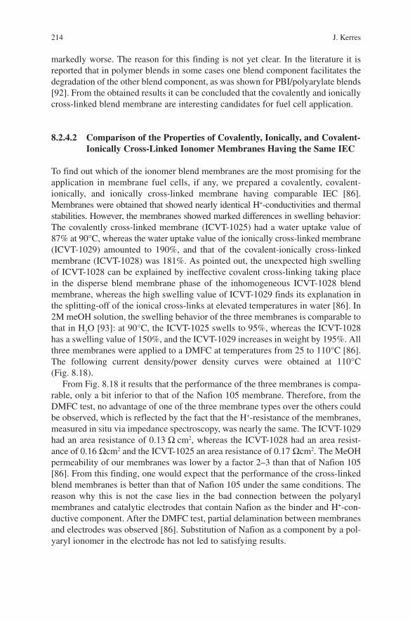
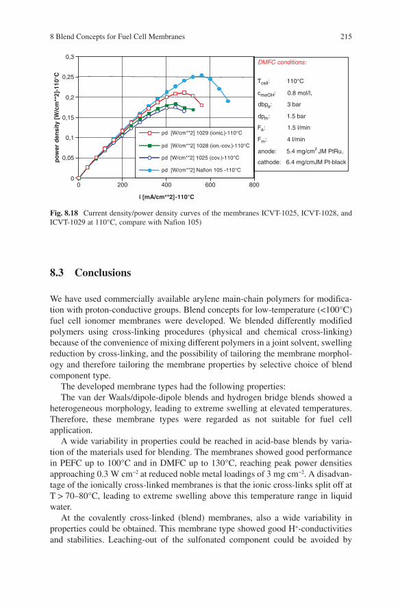
has a swelling value of 150%, and the ICVT-1029 increases in weight by 195%. All three membranes were applied to a DMFC at temperatures from 25 to 110 ° C [86] . The following current density/power density curves were obtained at 110 ° C (Fig. 8.18 ).
From Fig. 8.18 it results that the performance of the three membranes is compa-rable, only a bit inferior to that of the Nafion 105 membrane. Therefore, from the DMFC test, no advantage of one of the three membrane types over the others could be observed, which is reflected by the fact that the H + -resistance of the membranes, measured in situ via impedance spectroscopy, was nearly the same. The ICVT-1029 had an area resistance of 0.13 Ω cm 2 , whereas the ICVT-1028 had an area resist-ance of 0.16 Ω cm 2 and the ICVT-1025 an area resistance of 0.17 Ω cm 2 . The MeOH permeability of our membranes was lower by a factor 2 – 3 than that of Nafion 105 [86] . From this finding, one would expect that the performance of the cross-linked blend membranes is better than that of Nafion 105 under the same conditions. The reason why this is not the case lies in the bad connection between the polyaryl membranes and catalytic electrodes that contain Nafion as the binder and H + -con-ductive component. After the DMFC test, partial delamination between membranes and electrodes was observed [86] . Substitution of Nafion as a component by a pol-yaryl ionomer in the electrode has not led to satisfying results.
8 Blend Concepts for Fuel Cell Membranes 215
8.3 Conclusions
We have used commercially available arylene main-chain polymers for modifica-tion with proton-conductive groups. Blend concepts for low-temperature (<100 ° C) fuel cell ionomer membranes were developed. We blended differently modified polymers using cross-linking procedures (physical and chemical cross-linking) because of the convenience of mixing different polymers in a joint solvent, swelling reduction by cross-linking, and the possibility of tailoring the membrane morphol-ogy and therefore tailoring the membrane properties by selective choice of blend component type.
The developed membrane types had the following properties: The van der Waals/dipole-dipole blends and hydrogen bridge blends showed a
heterogeneous morphology, leading to extreme swelling at elevated temperatures. Therefore, these membrane types were regarded as not suitable for fuel cell application.
A wide variability in properties could be reached in acid-base blends by varia-tion of the materials used for blending. The membranes showed good performance in PEFC up to 100 ° C and in DMFC up to 130 ° C, reaching peak power densities approaching 0.3 W cm − 2 at reduced noble metal loadings of 3 mg cm − 2 . A disadvan-tage of the ionically cross-linked membranes is that the ionic cross-links split off at T > 70 – 80 ° C, leading to extreme swelling above this temperature range in liquid water.
At the covalently cross-linked (blend) membranes, also a wide variability in properties could be obtained. This membrane type showed good H + -conductivities and stabilities. Leaching-out of the sulfonated component could be avoided by
Fig. 8.18 Current density/power density curves of the membranes ICVT-1025, ICVT-1028, and ICVT-1029 at 110 ° C, compare with Nafion 105)
DMFC conditions:
Tcell: 110°C
cmeOH: 0.8 mol/l,
dbpa: 3 bar
dpm: 1.5 bar
Fa: 1.5 l/min
Fm: 4 l/min
anode: 5.4 mg/cm2 JM PtRu,
cathode: 6.4 mg/cmJM Pt-black
0
0,05
0,1
0,15
0,2
0,25
0,3p
ow
erd
ensi
ty [
W/c
m**
2]-1
10°C
0 200 400 600 800
i [mA/cm**2]-110°C
pd [W/cm**2] Nafion 105 -110°C
pd [W/cm**2] 1025 (cov.)-110°C
pd [W/cm**2] 1028 (ion.-cov.)-110°C
pd [W/cm**2] 1029 (ionic.)-110°C
216 J. Kerres
preparation of covalently cross-linked ionomeric networks from polymers carrying both sulfonic and sulfinate groups onto the same backbone. The covalently cross-linked membranes showed good performance in PEFC up to 100 ° C and in DMFC up to 130 ° C. A disadvantage of the covalently cross-linked membranes is that they tend to be brittle when they are drying out.
At the covalent-ionically cross-linked (blend) membranes, a wide range of dif-ferent properties was accessible by variation of the acidic, basic, and cross-linking components. The problem of morphologic heterogeneity and therefore extreme swelling of the ternary membranes at T > 60 – 80 ° C could be overcome by blending polymers carrying different types of functional groups onto the same backbone. The covalent-ionically cross-linked membranes showed good performance in DMFC up to T = 110 ° C.
Differently cross-linked organic-inorganic blend composite membranes were prepared from ionically or covalently cross-linked ionomer blend membranes by adding µ-sized inorganic powders to the solution of the organopolymers or hetero-polyacids to the organopolymer solution, and by ion-exchange of the formed organomembrane SO
3 H protons with metal cations such as ZrO 2+ and TiO 2+ fol-
lowed by immersion of the membrane in phosphoric acid, leading to precipitation of metal phosphates or metal hydrogenphosphates within the membrane matrix.
Blend membranes by mixing inorganic powders into the polymer solutions ended up in composite membranes containing large, agglomerated µ -sized parti-cles. Therefore, no positive effect of the inorganic phase to the H + -conductivity of the membranes could be found. Ionically cross-linked blend membranes prepared by addition of heteropolyacid powders to the polymer solution showed significant heteropolyacid leaching-out during the membrane post-treatment, which disquali-fies this membrane type for application in fuel cells. Blend membranes having a layered zirconium phosphate ZrP phase were transparent, indicating nanosized inorganic particles, and showed good H + -conductivity, and mechanical and thermal stability. Application of one of these composite membranes to a PEFC yielded good performance up to T = 115 ° C.
In the future, we will focus onto the following membrane systems. We will further develop membranes from arylene main-chain polymers carrying
both sulfonate and sulfinate groups onto the same backbone. Moreover, partially fluorinated covalent ionomer networks, which show an improved chemical and thermal stability, compared with non-fluorinated systems, will be prepared. We will concentrate on the further development of blend membranes of sulfonated poly(etherketone)s with stable and strong polybases such as poly(benzimidazole)s, due to their high durability. The development of morphologically homogeneous ionomer membranes by preparation and further development of polyarylenes car-rying several types of functional groups on the same backbone to avoid phase sepa-ration will be continued. Finally, we will concentrate onto the further development of differently cross-linked hybrid membrane systems having ZrP-type inorganic phase. Our objective is to obtain membranes whose inorganic phase is both proton conductive and serves as water storage to allow fuel cell operation in the tempera-ture range 100 – 150 ° C.
8 Blend Concepts for Fuel Cell Membranes 217
References
1. J. Kerres, Development of ionomer membranes for fuel cells, J. Membr. Sci. 185 , 3 – 27 (2001)
2. J. Wei, C. Stone, A. E. Steck, US 5,773,480; June 30, 1998 3. C. Stone, C. L. Q. Hu, T. Daynard, C. Mah, Lecture, 3rd International Symposium on New
Materials for Electrochemical Systems, 4th to 8th July 1999, Montreal, Canada 4. A. E. Steck, C. Stone, in: “ Proceedings of the Second International Symposium on New
Materials for Fuel Cell and Modern Battery Systems ” , Eds. O. Savadogo, P. R. Roberge, Montreal, Canada, July 6 – 10, 1997, p. 792
5. H. P. Brack, D. Ruegg, H. B ü hrer, M. Slaski, S. Alkan, G. G. Scherer, Differential scanning calorimetry and thermogravimetric analysis investigation of the thermal properties and degra-dation of some radiation-grafted films and membranes, J. Polym. Sci. Part B: Polym. Phys. 42 , 2612 – 2624 (2004)
6. P. Gode, J. Ihonen, A. Strandroth, H. Ericson, G. Lindbergh, M. Paronen, F. Sundholm, G. Sundholm, N. Walsby, Membrane durability in a PEM fuel cell studied using PVDF based radiation grafted membranes, Fuel Cells 3 , 21 – 27 (2004)
7. G. D. Alelio, US 2,366,007; December 12,1944 8. N. Ogato, M. Rikukawa, US 5,403,675; April 4, 1995 9. A. Noshay, L. M. Robeson, Sulfonated polysulfone, J. Appl. Polym. Sci. 20 , 1885 – 1903
(1976) 10. B. C. Johnson, I. Yilg ö r, C. Tran, M. Iqbal, J. P. Wightman, D. R. Lloyd, J. E. McGrath,
Synthesis and characterization of sulfonated poly(acrylene ether sulfones), J. Polym. Sci. Polym. Chem. Ed. 22 , 721 – 737 (1984)
11. J. Kerres, W. Cui, S. Reichle, New sulfonated engineering polymers via the metalation route. I. Sulfonated poly(ethersulfone) PSU Udel ® via metalation-sulfination-oxidation, J. Polym. Sci. Part A: Polym. Chem. 34 , 2421 – 2438 (1996)
12. F. Helmer-Metzmann, F. Osan, A. Schneller, H. Ritter, K. Ledjeff, R. Nolte, R. Thorwirth, EP 0574 791 B1, 22.12.1999
13. J. Rozi è re, D. J. Jones, Non-fluorinated polymer materials for proton exchange membrane fuel cells, Annu. Rev. Mater. Res. 33 , 503 – 555 (2003)
14. H. H. Ulrich, G. Rafler, Sulfonated Poly(aryl ether ketone)s, Angew. Makromol. Chem. 263 , 71 – 78 (1998)
15. P. Xing, G. P. Robertson, M. D. Guiver, S. D. Mikhailenko, K. Wang, S. Kaliaguine, Synthesis and characterization of sulfonated poly(ether ether ketone) for proton exchange membranes, J. Membr. Sci. 229 , 95 – 106 (2004)
16. J. Schauer, P. Lopour, J. Vacik, The preparation of ultrafiltration membranes from a moder-ately sulfonated poly(oxy(2,6-Dimethyl-1,4-Phenylene), J. Membr. Sci. 29 , 169 – 175 (1992)
17. S. Percec, G. Li, Chemical modification of poly(2,6-Dimethyl 1,4-Phenylene Oxide) and properties of the resulting copolymers, Polym. Prepr. (Am. Chem. Soc., Div. Polym. Chem.) 27 (2), 19 – 20 (1986)
18. K. Miyatake, H. Iyotani, K. Yamamoto, E. Tsuchida, Synthesis of poly(phenylene sulfide sul-fonic acid) via poly(sulfonium cation) as a thermostable proton-conducting polymer, Macromolecules . 29 , 6969 – 6971 (1996)
19. Q. Guo, P. N. Pintauro, H. Tang, S. O Connor, Sulfonated and crosslinked polyphosphazene-based proton-exchange membranes, J. Membr. Sci. 154 , 175 – 181 (1999)
20. H. R. Allcock, M. A. Hofmann, C. M. Ambler, S. N. Lvov, X. Y. Zhou, E. Chalkova, J. Weston, Phenyl phosphonic acid functionalized poly[aryloxyphosphazenes] as proton-con-ducting membranes for direct methanol fuel cells, J. Membr. Sci. 201 , 47 – 54 (2002)
21. I. Gautier-Luneau, A. Denoyelle, J. Y. Sanchez, C. Poinsignon, Organicinorganic protonic polymer electrolytes as membrane for low-temperature fuel cell, Electrochim. Acta 37 , 1615 – 1618 (1992)
22. K. Tabata, F. Fujibayashi, M. Aimu, US 6,723,464; April 20, 2004
218 J. Kerres
23. M. Murthy, M. Esayian, A. Hobson, S. MacKenzie, W. Lee, J. W. van Zee, Performance of a polymer electrolyte membrane fuel cell exposed to transient CO concentrations, J. Electrochem. Soc. 148 , A1141 – A1147 (2001)
24. R. F. Savinell, M. H. Litt, US 5,525,436; June 11, 1996 25. J. S. Wainright, J.-T. Wang, D. Weng, R. F. Savinell, M. H. Litt, Acid-doped polybenzimida-
zoles: a new polymer electrolyte, J. Electrochem. Soc. 142 , L121 – L123 (1995) 26. G. Calundann, M. Sansone, B. Benicewicz, E. W. Choe, Oe. Uensal, J. Kiefer, DE 10246459
A1, 2004 27. Y. L. Ma, J. S. Wainright, M. H. Litt, R. F. Savinell, Conductivity of PBI membranes for
high-temperature polymer electrolyte fuel cells, J. Electrochem. Soc. 151 (1) A8 – A16 (2004)
28. K. D. Kreuer, On the development of proton conducting polymer membranes for hydrogen and methanol fuel cells, J. Membr. Science 185 , 29 – 39 (2001)
29. M. Schuster, Protonenleitung in imidazolhaltigen Materialien als Modellsysteme f ü r wasserfreie Brennstoffzellenmembranen , Ph.D. Dissertation, University of Mainz 2002; avail-able via Internet: http://archimed.uni-mainz.de/pub/2002/0017/diss.pdf
30. S. M. J. Zaidi, S. D. Mikhailenko, G. P. Robertson, M. D. Guiver, S. Kaliaguine, Proton con-ducting composite membranes from polyether ether ketone and heteropolyacids for fuel cell applications, J. Membr. Sci. 173 , 17 – 34 (2000)
31. M. L. Ponce, L. Prado, B. Ruffmann, K. Richau, R. Mohr, S. P. Nunes, Reduction of methanol permeability in polyetherketone-heteropolyacid membranes, J. Membr. Sci. 217 , 5 – 15 (2003)
32. Y. S. Kim, F. Wang, M. Hickner, T. A. Zawodzinski, T. A. J. E. McGrath, Fabrication and characterization of heteropolyacid (H
3 PW
12 O
40 )/directly polymerized sulfonated poly(arylene
ether sulfone) copolymer composite membranes for higher temperature fuel cell applications, J. Membr. Sci. 212 , 263 – 282 (2002)
33. A. S. Aric ò , P. Cret ì , P. L. Antonucci, V. Antonucci, Comparison of ethanol and methanol oxidation in a liquid-feed solid polymer electrolyte fuel cell at high temperature, Electrochem. Solid-State Lett. 1 (2), 66 – 68 (1998)
34. K. T. Adjemian, S. J. Lee, S. Srinivasan, J. Benziger, A. B. Bocarsly, Silicon oxide Nafion ® composite membranes for proton-exchange membrane fuel cell operation at 80 – 140 ° C, J. Electrochem. Soc. 149 (3), A256 – A261 (2002)
35. I. Honma, H. Nakajima, O. Nishikawa, T. Sugimoto, S. Nomura, Amphiphilic organic/inor-ganic nanohybrid macromolecules for intermediate-temperature proton conducting electrolyte membranes, J. Electrochem. Soc. 149 (10), A1389 – A1392 (2002)
36. K. A. Mauritz, Organic-inorganic hybrid materials: perfluorinated ionomers as sol-gel polym-erization templates for inorganic alkoxides, Mat. Sci. Eng. C6 , 121 – 133 (1998)
37. C. Yang, S. Srinivasan, A. S. Aric ò , P. Creti, V. Baglio, V. Antonucci, Composite Nafion ® /zirconium phosphate membranes for direct methanol fuel cell operation at high temperature, Electrochem. Solid-State Lett. 4 (4), A31 – A34 (2001)
38. G. Alberti, M. Casciola, Composite membranes for medium-temperature PEM fuel cells, Annu. Rev. Mater. Res. 33 (1), 129 – 154 (2003)
39. K. T. Adjemian, S. Srinivasan, J. Benziger, A. B. Bocarsly, Investigation of PEMFC operation above 100 ° C employing perfluorosulfonic acid silicon oxide composite membranes, J. Power Sources 109 (2), 356 – 364 (2002)
40. S. C. Yeo, A. Eisenberg, Physical properties and supermolecular structure of perfluorinated ion-containing (Nafion ® ) polymers, J. Appl. Polym. Sci. 21 , 875 – 898 (1977)
41. X. Ren, T. E. Springer, S. Gottesfeld, Water and methanol uptakes in Nafion ® membranes and membrane effects on direct methanol cell performance, J. Electrochem. Soc. 147 , 92 – 98 (2000)
42. V. M. Barrag á n, C. Ruiz-Bauz á , J. P. G. Villaluenga, B. Seoane, Transport of methanol and water through Nafion ® membranes, J. Power Sources 130 (1 – 2), 22 – 29 (2004)
8 Blend Concepts for Fuel Cell Membranes 219
43. W. Zhang, C. -M. Tang, J. Kerres, Development and characterization of sulfonated-unmodi-fied and sulfonated-aminated PSU Udel ® blend membranes, Sep. Purif. Technol. 22 , 209 – 221 (2001)
44. W. Cui, J. Kerres, G. Eigenberger, Development and characterization of ion-exchange poly-mer blend membranes, Sep. Purif. Technol. 14 , 145 – 154 (1998)
45. J. Kerres, W. Cui, US 6,194,474; 27 Feb 2001 J. Kerres, W. Cui, US 6,300,381; 9 October, 2001 J. Kerres, W. Cui, EP 1,073,690, 14 January, 2004
46. J. Kerres, A. Ullrich, T. H ä ring, EP 1,076,676, 28 January, 2004 J. Kerres, A. Ullrich, T. H ä ring, US 6,723,757, 20 April, 2004
47. J. Kerres, A. Ullrich, T. H ä ring, US 6,590,067, 8 July, 2003 48. W. Cui, J. Kerres, DE Appl. 198 13 613.7; 27 March, 1998 49. C. Manea, M. Mulder, New polymeric electrolyte membranes based on proton donor-proton
acceptor properties for direct methanol fuel cells, Desalination 147 , 179 – 182 (2002) 50. M. Walker, K.-M. Baumg ä rtner, M. Kaiser, J. Kerres, A. Ullrich, E. R ä uchle, Proton conduct-
ing polymers with reduced methanol permeation, J. Appl. Polym. Sci. 74 , 67 – 73 (1999) 51. L. J ö rissen, V. Gogel, J. Kerres, J. Garche, New membranes for direct methanol fuel cells, J.
Power Sources 105 , 267 – 273 (2002) 52. B. Kosmala, J. Schauer, Ion-exchange membranes prepared by blending sulfonated poly(2,6-
dimethyl-1,4-phenylene oxide) with polybenzimidazole, J. Appl. Polym. Sci. 85 , 1118 – 1127 (2002)
53. K. Bouzek, S. Moravcova, Z. Samec, J. Schauer, H + and Na + Ion transport properties of sul-fonated poly(2,6-dimethyl-1,4-phenyleneoxide) membranes, J. Electrochem. Soc. 150 (6) E329 – E336 (2003)
54. J. Kerres, A. Ullrich, T. H. H ä ring, M. Baldauf, U. Gebhardt, W. Preidel, Preparation, charac-erization, and fuel cell application of new acid-base blend membranes, J. New Mater. Electrochem. Syst. 3 , 229 – 239 (2000)
55. S. Motupally, V. Lightner, U. S. Department of Energy, Energy Efficiency and Renewable Energy, Hydrogen, Fuel Cells and Infrastructure Technologies Program, FY 2003 Progress Report, p. 7
56. C. Hasiotis, Q. Li, V. Deimede, J. K. Kallitsis, C. G. Kontoyannis, N. J. Bjerrum, Development and characterization of acid-doped polybenzimidazole/sulfonated polysulfone blend polymer electrolytes for fuel cells, J. Electrochem. Soc. 148 (5) A513 – A519 (2001)
57. R. Nolte, K. Ledjeff, M. Bauer, R. M ü lhaupt, Partially sulfonated poly(arylene ether sulfone) - a versatile proton conducting membrane material for modern energy conversion technolo-gies, J. Membr. Sci. 83 , 211 – 220 (1993)
58. S. D. Mikhailenko, K. Wang, S. Kaliaguine, P. Xing, G. P. Robertson, M. D. Guiver, Proton conducting membranes based on cross-linked sulfonated poly(ether ether ketone) (SPEEK), J. Membr. Sci. 233 , 93 – 99 (2004)
59. J. Kerres, W. Cui, W. Schnurnberger, DE 196 22 237.7; 12 March, 1998, US 6,221,923; 24 April, 2001, US 6,552,135; 22 April, 2003
60. J. Kerres, W. Zhang, C.-M. Tang, DE Appl. 10024576;19 May, 2000, Int. Appl. PCT/EP200105644 from 17th May, 2001
61. D. J. Jones, M. El Haddad, B. Mula, J. Rozi è re, New proton conductors for fuel cell applica-tions , Environmental Research Forum “ Chemistry and Energy ” , C. A. C. Sequeira, Ed., Transtec, 1 – 2, pp. 115 – 126 (1996)
62. J. Rozi è re, D. J. Jones, Inorganic-organic Composite Membranes for PEM Fuel Cells , Handbook of Fuel Cell Technology, W. Vielstich, A. Lamm, H. Gasteiger, Eds., Wiley, Vol. 3, pp. 447 – 455 (2003)
63. B. Bauer, D. J. Jones, J. Rozi è re, L. Tchicaya, G. Alberti, L. Massinelli, M. Casciola, A. Peraio, and E. Ramunni, Hybrid organic-inorganic membranes for a medium temperature fuel cell, J. New Mater. Electrochem. Appl. 3 , 87 – 92 (2000)
64. D. J. Jones, J. Roziere, Recent advances in the functionalisation of polybenzimidazole and polyetherketone for fuel cell applications, J. Membr. Sci. 185 , 41 – 58 (2001)
220 J. Kerres
65. L. Tchicaya-Bouckary, D. J. Jones, J. Rozi è re, Hybrid polyaryletherketone membranes for fuel cell applications, Fuel Cells 2 , 40 – 45 (2002)
66. K. D. Kreuer, Proton conductivity: materials and applications, Chem. Materials 8 , 610 – 641 (1996)
67. S. Kaliuguine, S. D. Mikhailenko, K. P. Wang, P. Xing, G. P. Robertson, M. D. Guiver, Properties of SPEEK based PEMs for fuel cell application, Catalysis Today 82 , 213 – 222 (2003)
68. J. Kerres, C.-M. Tang, C. Graf, Improvement of properties of poly(ether ketone) ionomer membranes by blending and cross-linking, Ind. Eng. Chem. Res. 43 (16), 4571 – 4579 (2004)
69. M. D. Guiver, Aromatic Polysulfones Containing Functional Groups by Synthesis and Chemical Modification , Ph.D. Dissertation, Carletown University 1987
70. J. A. Kerres, A. J. van Zyl, Development of new ionomer blend membranes, their characteri-zation and their application in the perstractive separation of alkenes from alkene-alkane mix-tures. 1. Polymer modification, ionomer blend membrane preparation and characterization, J. Appl. Polym. Sci. 74 , 428 – 438 (1999)
71. J. Kerres, W. Zhang, W. Cui, New sulfonated engineering polymers via the metalation route. 2. Sulfinated-Sulfonated Poly(ethersulfone) PSU Udel ® and its crosslinking, J. Polym. Sci.: Part A: Polym. Chem. 36 , 1441 – 1448 (1998)
72. J. Kerres, W. Zhang, T. Häring, DE Appl. 102 09 784.4 from 28th Febr., 2002, Int. Appl. PCT/DE02/03260 from 2nd Sept., 2002 W. Zhang, V. Gogel, K. A. Friedrich, J. Kerres, Novel covalently cross-linked poly(etheretherketone) ionomer membranes, J. Power Sources 155 (1), 3 – 12 (2006)
73. M. D. Guiver, G. P. Robertson, Chemical modification of polysulfones: a facile method of preparing azide derivatives from lithiated polysulfone intermediates, Macromolecules. 28 , 294 – 301 (1995)
74. M. D. Guiver, G. P. Robertson, S. Foley, Chemical modification of Polysulfones II: an effi-cient method for introducing primary amine groups onto the aromatic chain, Macromolecules 28 , 7612 – 7621 (1995)
75. C. M. Tang, W. Zhang, J. Kerres, Preparation and characterization of ionically cross-linked proton-conducting membranes, J. New Mat. Electrochem. Syst. 7 , 287 – 298 (2004)
76. H. A. Naik, I. W. Parsons, P. T. McGrail, P. D. MacKenzie, Chemical modification of pol-yarylene ether/sulphone polymers: preparation and properties of materials aminated on the main chain, Polymer 32 (1), 140 – 145 (1991)
77. J. Kerres, A. Ullrich, M. Hein, Preparation and characterization of novel basic polysulfone polymers, J. Polym. Sci.: Part A: Polym. Chem. 39 , 2874 – 2888 (2001)
78. J. Kerres, A. Ullrich, Synthesis of novel engineering polymers containing basic side groups and their application in acid-base polymer blend membranes, Sep. Purif. Technol. 22 , 1 – 15 (2001)
79. J. Kerres, W. Zhang, A. Ullrich, C.-M. Tang, M. Hein, V. Gogel, T. Frey, L. J ö rissen, Synthesis and characterization of polyaryl blend membranes having different composition, different covalent and/or ionical cross-linking density, and their application to DMFC, Desalination 147 , 173 – 178 (2002)
80. J. Kerres, M. Hein, W. Zhang, N. Nicoloso, S. Graf, Development of new blend mem-branes for polymer electrolyte fuel cell applications, J. New Mat. Electrochem. Syst. 6 (4), 223 – 229 (2003)
81. J. Kerres, A. Ullrich, F. Meier, Th. H ä ring, Synthesis and characterization of novel acid-base polymer blends for application in membrane fuel cells, Solid State Ionics 125 , 243 – 249 (1999)
82. D. R. Coffin, G. A. Serad, H. L. Hicks, R. T. Montgomery, Properties and applications of celanese PBI-Polybenzimidazole fiber, Textile Res. J. 52 (7), 466 – 472 (1982)
83. A. Panchenko, H. Dilger, J. Kerres, M. Hein, A. Ullrich, T. Kaz, E. Roduner, In-situ spin trap electron paramagnetic resonance study of fuel cell processes, Phys. Chem. Chem. Phys. 6 , 2891 – 2894 (2004)
8 Blend Concepts for Fuel Cell Membranes 221
84. J. Kerres, A. Ullrich, M. Hein, V. Gogel, K. A. Friedrich, L. J ö rissen, Cross-linked polyaryl blend membranes for polymer electrolyte fuel cells, Fuel Cells 4 , 105 – 112 (2004)
85. E. Roduner, A. Panchenko, J. Kerres, unpublished results 86. J. Kerres, W. Zhang, L. J ö rissen, V. Gogel, Application of different types of polyaryl-blend-
membranes in DMFC, J. New Mat. Electrochem. Syst. 5 , 97 – 107 (2002) 87. J. Kerres, M. Hein, W. Zhang, N. Nicoloso, S. Graf, S., Invited lecture (J. Kerres), 5th
International Symposium “ New Materials for Electrochemical Systems ” , 6. to 11. July 2003, Montreal, Canada J. Kerres, W. Zhang, T. H ä ring, Covalently cross-linked ionomer (blend) membranes for fuel cells, J. New Mat. Electrochem. Syst. 7 , 299 – 309 (2004)
88. J. Kerres, Invited Lecture, 204th Meeting of The Electrochemical Society, October 12-October 16, 2003, Orlando, Florida, proceedings submitted
89. J. Kerres, Invited lecture, Symposium “ Advances in Materials for Proton Exchange Membrane Fuel Cell Systems ” , February 23 – 27, 2003, Asilomar, California.
90. J. Kerres, DE Appl. 103 08 462.2 from 19th February, 2003 91. J. Kerres, W. Zhang, unpublished results 92. T. S. Chung, P. N. Chen, Polybenzimidazole (PBI) and polyarylate blends, J. Appl. Polym. Sci.
40 , 1209 – 1222 (1990) 93. F. Meier, J. Kerres, G. Eigenberger, Characterization of polyaryl-blend-membranes for DMFC
application J. New Mat. Electrochem. Syst. 5 , 91 – 96 (2002)


![[PPT]PowerPoint Presentation - Kansas State · Web viewBiodiesel blend, n. -- a blend of biodiesel fuel meeting ASTM D 6751 with petroleum-based diesel fuel designated BXX, where XX](https://img.pdfslide.net/doc/110x75/5ab0c6fb7f8b9ac3348b8f1d/pptpowerpoint-presentation-kansas-state-viewbiodiesel-blend-n-a-blend-of.jpg)