1
Power Electronics Laboratory Switching Power Pole Board BB Board Flyback Forward Board Schematic Flyback Converter Controller Board Buck Converter Circuit Diagram PWM pulses and Inductor Current Boost Converter Circuit Diagram PWM pulses and Input Current Circuit Diagram Forward Converter Circuit Diagram Voltage-Mode Control Transfer function calculated using a perturbation at duty ratio and measuring output voltage perturbation in PSpice Controller is deigned and implemented using an R-C circuit Vendor Information HiRel Systems LLC Lois King Phone: 218-727-3115 Ext. 14 Fax: 218-727-0331 [email protected] Manual, Schematic & other info: http://www.ece.umn.edu/groups/power Budget Power Pole Board: $1145.00 () () o v s ds % % Output voltage response for a step change in load Extends the switching power-pole concept Configurable to perform variety of experiments Input and output current sensors Overvoltage and overcurrent protection Both analog and digital control possible w/o feedback control w/ feedback control Input Current and Primary Switch Voltage Primary and Secondary Winding Currents

Power Electronics Laboratory - University Minnesota System

  • Upload
    others

  • View
    2

  • Download
    0

Embed Size (px)

Citation preview

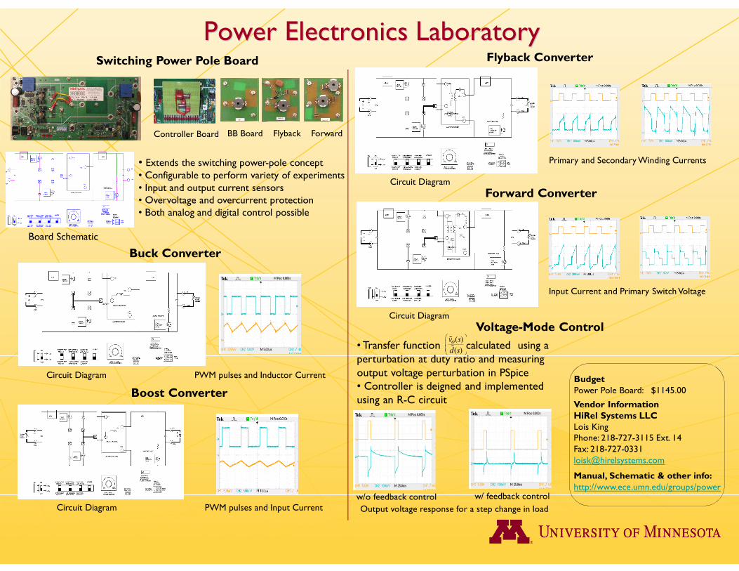
Power Electronics LaboratorySwitching Power Pole Board

BB Board Flyback Forward

Board Schematic

Flyback Converter

Controller Board

Buck Converter

Circuit Diagram PWM pulses and Inductor Current

Boost Converter

Circuit Diagram PWM pulses and Input Current

Circuit Diagram

Forward Converter

Circuit Diagram

Voltage-Mode Control

• Transfer function calculated using a perturbation at duty ratio and measuring output voltage perturbation in PSpice• Controller is deigned and implemented using an R-C circuit Vendor Information

HiRel Systems LLCLois KingPhone: 218-727-3115 Ext. 14Fax: [email protected]

Manual, Schematic & other info:http://www.ece.umn.edu/groups/power

BudgetPower Pole Board: $1145.00

( )

( )

ov s

d s

%

%

Output voltage response for a step change in load

• Extends the switching power-pole concept• Configurable to perform variety of experiments• Input and output current sensors• Overvoltage and overcurrent protection• Both analog and digital control possible

w/o feedback control w/ feedback control

Input Current and Primary Switch Voltage

Primary and Secondary Winding Currents