Embed Size (px)
DESCRIPTION
power flow with FACTS
Citation preview
13
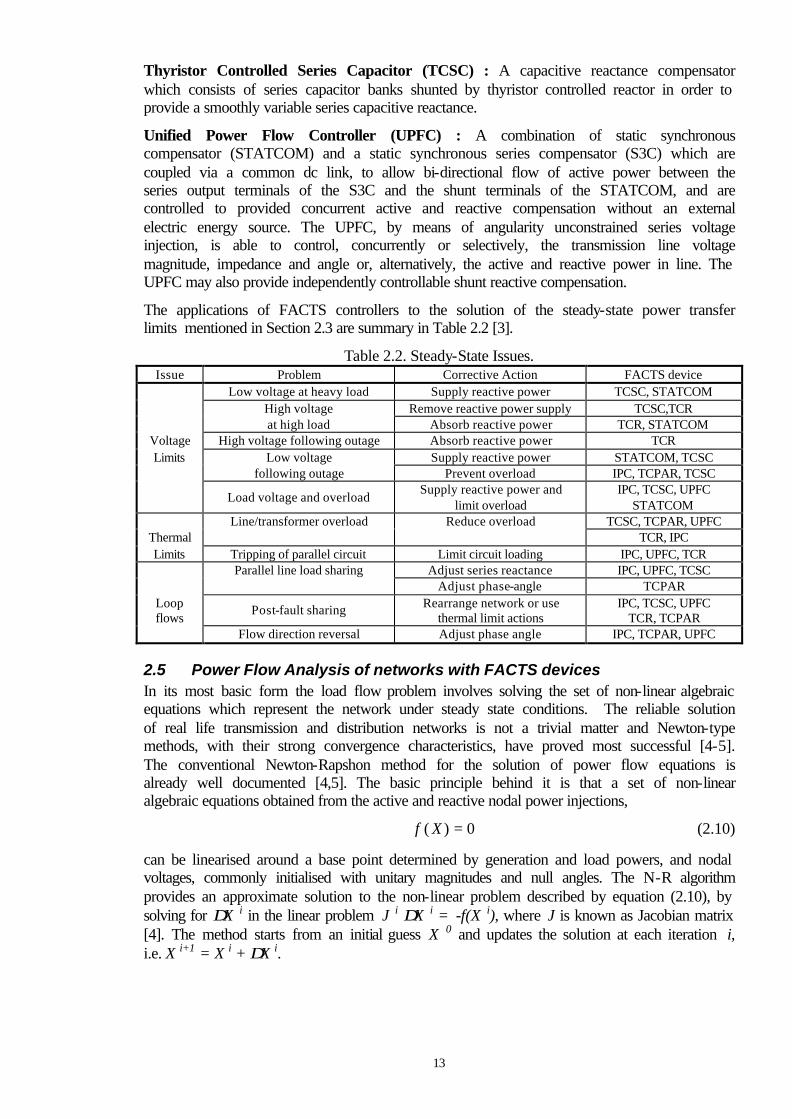
Thyristor Controlled Series Capacitor (TCSC) : A capacitive reactance compensator which consists of series capacitor banks shunted by thyristor controlled reactor in order to provide a smoothly variable series capacitive reactance. Unified Power Flow Controller (UPFC) : A combination of static synchronous compensator (STATCOM) and a static synchronous series compensator (S3C) which are coupled via a common dc link, to allow bi-directional flow of active power between the series output terminals of the S3C and the shunt terminals of the STATCOM, and are controlled to provided concurrent active and reactive compensation without an external electric energy source. The UPFC, by means of angularity unconstrained series voltage injection, is able to control, concurrently or selectively, the transmission line voltage magnitude, impedance and angle or, alternatively, the active and reactive power in line. The UPFC may also provide independently controllable shunt reactive compensation. The applications of FACTS controllers to the solution of the steady-state power transfer limits mentioned in Section 2.3 are summary in Table 2.2 [3].
Table 2.2. Steady-State Issues. Issue Problem Corrective Action FACTS device
Low voltage at heavy load Supply reactive power TCSC, STATCOM High voltage Remove reactive power supply TCSC,TCR at high load Absorb reactive power TCR, STATCOM
Voltage High voltage following outage Absorb reactive power TCR Limits Low voltage Supply reactive power STATCOM, TCSC
following outage Prevent overload IPC, TCPAR, TCSC
Load voltage and overload Supply reactive power and
limit overload IPC, TCSC, UPFC
STATCOM Line/transformer overload Reduce overload TCSC, TCPAR, UPFC
Thermal TCR, IPC Limits Tripping of parallel circuit Limit circuit loading IPC, UPFC, TCR
Parallel line load sharing Adjust series reactance IPC, UPFC, TCSC Adjust phase-angle TCPAR
Loop flows
Post-fault sharing Rearrange network or use
thermal limit actions IPC, TCSC, UPFC
TCR, TCPAR Flow direction reversal Adjust phase angle IPC, TCPAR, UPFC
2.5 Power Flow Analysis of networks with FACTS devices In its most basic form the load flow problem involves solving the set of non-linear algebraic equations which represent the network under steady state conditions. The reliable solution of real life transmission and distribution networks is not a trivial matter and Newton-type methods, with their strong convergence characteristics, have proved most successful [4-5]. The conventional Newton-Rapshon method for the solution of power flow equations is already well documented [4,5]. The basic principle behind it is that a set of non-linear algebraic equations obtained from the active and reactive nodal power injections,
f X( ) = 0 (2.10) can be linearised around a base point determined by generation and load powers, and nodal voltages, commonly initialised with unitary magnitudes and null angles. The N-R algorithm provides an approximate solution to the non-linear problem described by equation (2.10), by solving for ∆X i in the linear problem J i ∆X i = -f(X i), where J is known as Jacobian matrix [4]. The method starts from an initial guess X 0 and updates the solution at each iteration i, i.e. X i+1 = X i + ∆X i.
14
Over the years, special algorithms have been put forward which have addressed the modelling of controllable devices in Newton’s method, such as Load Tap Changing (LTC) and phase shifting transformers, series and shunt variable compensation. The methods used for the modelling of controllable devices can be broadly classified into two main categories: sequential and simultaneous solution method. References [5-11] are just but a few of the long list of published work in this area using sequential methods. However, a major drawback in all these methods is that the nodal voltage magnitudes and angles are the only state variables which are calculated in true Newton fashion, whilst a sub-problem is formulated for updating the state variables of the controllable devices at the end of each Newton-Raphson iteration. These methods are mathematically formulated for a system of non-linear algebraic equations of the form,
f X RnAC nF( , ) = 0 (2.11)
F X RnAC nF( , ) = 0 (2.12) where f(XnAC , RnF)=0 represents the vector functions of nodal AC network equations, F(XnAC , RnF)=0 describes the vector functions of FACTS device equations, XnAC is the vector of all AC system state variables given by the nodal voltage angles and magnitudes, and RnF is the vector of all FACTS devices state variables. These vectors are expressed as,
f f f f nACT= [ , ,..., ]1 2 (2.13)
F F F FnF
T= [ , ,..., ]1 2 (2.14)
X x x xnAC nACT= [ , ,..., ]1 2 (2.15)
R r r rnF nF
T= [ , ,..., ]1 2 (2.16) The sequential solutions start with an initial guess (Xo
nAC, RonF). Equation (2.11) is solved
for X1nAC keeping Ro
nF fixed, then equation (2.12) is solved for R1nF with X1
nAC fixed. The method continues solving sequentially one set of equations after the other with initial values given by the previous solution until a predefined convergence criteria is satisfied for both set of equations. This sequential iterative approach is rather attractive because it is straightforward to implement in existing Newton-Raphson programs but caution has to be exercised because it will yield no quadratic convergence. A fundamentally different approach for the modelling of controllable devices, within the context of the load flow problem, was developed at a very early stage by Peterson and Scott Meyer [12]. It is a highly efficient method which combines simultaneously the state variables corresponding to the controllable devices with the nodal voltage magnitudes and angles of the network in a single frame-of-reference for a unified, iterative solution through a Newton-Rapshon technique. The method retains Newton’s quadratic convergence characteristics. Two types of controllable devices were addressed is that work, namely LTCs and phase-shifting transformers. The method is not necessarily easy to implement. It requires the Jacobian matrix to be modified in order to incorporate the contributions corresponding to LTCs and phase-shifters. In such iterative environment the state variables of LTCs are adjusted automatically so as to satisfy specified voltage magnitudes and the state variables of the phase-shifters are adjusted automatically so as to satisfy specified power flows.
15
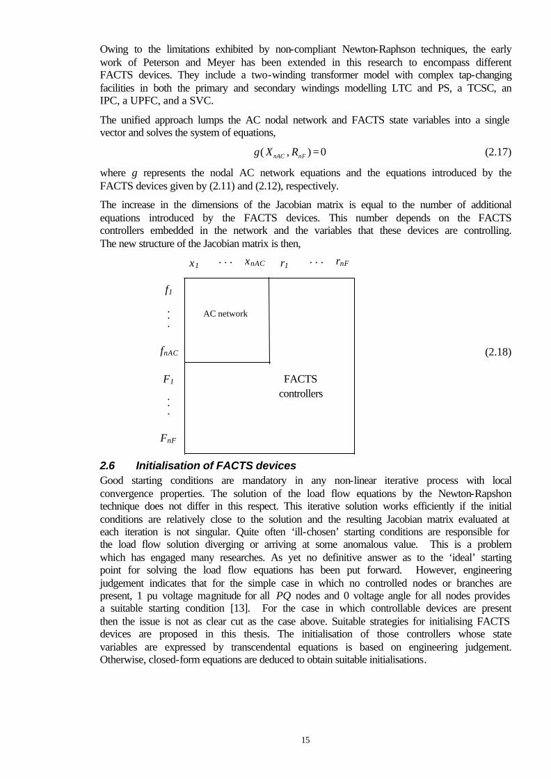
Owing to the limitations exhibited by non-compliant Newton-Raphson techniques, the early work of Peterson and Meyer has been extended in this research to encompass different FACTS devices. They include a two-winding transformer model with complex tap-changing facilities in both the primary and secondary windings modelling LTC and PS, a TCSC, an IPC, a UPFC, and a SVC. The unified approach lumps the AC nodal network and FACTS state variables into a single vector and solves the system of equations,
g X RnAC nF( , ) = 0 (2.17) where g represents the nodal AC network equations and the equations introduced by the FACTS devices given by (2.11) and (2.12), respectively. The increase in the dimensions of the Jacobian matrix is equal to the number of additional equations introduced by the FACTS devices. This number depends on the FACTS controllers embedded in the network and the variables that these devices are controlling. The new structure of the Jacobian matrix is then,
2.6 Initialisation of FACTS devices Good starting conditions are mandatory in any non-linear iterative process with local convergence properties. The solution of the load flow equations by the Newton-Rapshon technique does not differ in this respect. This iterative solution works efficiently if the initial conditions are relatively close to the solution and the resulting Jacobian matrix evaluated at each iteration is not singular. Quite often ‘ill-chosen’ starting conditions are responsible for the load flow solution diverging or arriving at some anomalous value. This is a problem which has engaged many researches. As yet no definitive answer as to the ‘ideal’ starting point for solving the load flow equations has been put forward. However, engineering judgement indicates that for the simple case in which no controlled nodes or branches are present, 1 pu voltage magnitude for all PQ nodes and 0 voltage angle for all nodes provides a suitable starting condition [13]. For the case in which controllable devices are present then the issue is not as clear cut as the case above. Suitable strategies for initialising FACTS devices are proposed in this thesis. The initialisation of those controllers whose state variables are expressed by transcendental equations is based on engineering judgement. Otherwise, closed-form equations are deduced to obtain suitable initialisations.
x1 xnAC . . . r1 rnF . . .
f1
. .
.
fnAC
F1
. .
.
FnF
AC network
FACTS controllers
(2.18)