Embed Size (px)
Citation preview
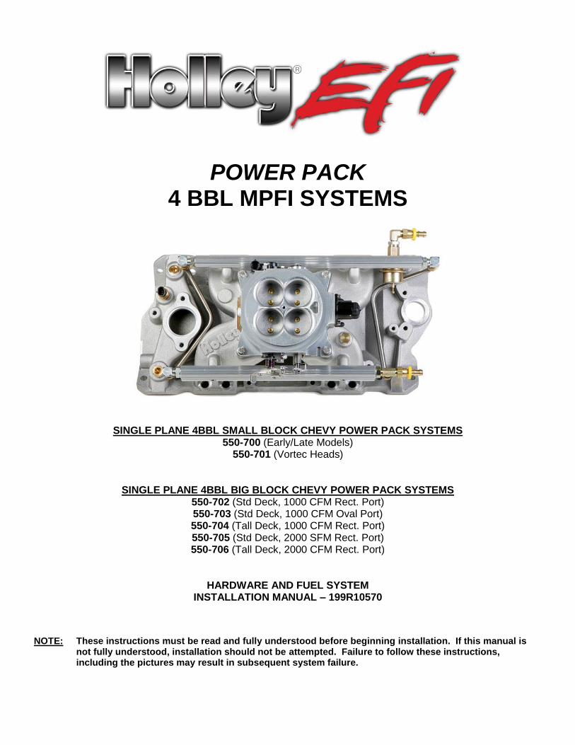
POWER PACK 4 BBL MPFI SYSTEMS
SINGLE PLANE 4BBL SMALL BLOCK CHEVY POWER PACK SYSTEMS 550-700 (Early/Late Models)
550-701 (Vortec Heads)
SINGLE PLANE 4BBL BIG BLOCK CHEVY POWER PACK SYSTEMS 550-702 (Std Deck, 1000 CFM Rect. Port) 550-703 (Std Deck, 1000 CFM Oval Port) 550-704 (Tall Deck, 1000 CFM Rect. Port) 550-705 (Std Deck, 2000 SFM Rect. Port) 550-706 (Tall Deck, 2000 CFM Rect. Port)
HARDWARE AND FUEL SYSTEM INSTALLATION MANUAL – 199R10570
NOTE: These instructions must be read and fully understood before beginning installation. If this manual is
not fully understood, installation should not be attempted. Failure to follow these instructions, including the pictures may result in subsequent system failure.
2
TABLE OF CONTENTS 1.0 INTRODUCTION .............................................................................................................................................................. 2
2.0 BEFORE YOU BEGIN ..................................................................................................................................................... 3
3.0 WARNINGS, NOTES, AND NOTICES ............................................................................................................................ 3
4.0 SKILL LEVEL REQUIRED .............................................................................................................................................. 3
5.0 ADDITIONAL ITEMS REQUIRED FOR INSTALLATION ............................................................................................... 3
6.0 TOOLS REQUIRED FOR INSTALLATION ..................................................................................................................... 4
7.0 POWER PACK EFI SYSTEM OPTIONS ......................................................................................................................... 4
8.0 REMOVAL OF EXISTING FUEL SYSTEM ..................................................................................................................... 4
8.1 Preparing the Manifold for Installation ..................................................................................................................... 4
8.2 Installation of POWER PACK EFI Manifold .............................................................................................................. 4
8.3 Installing the distributor ............................................................................................................................................. 6
8.4 Vacuum Line Connections ......................................................................................................................................... 6
9.0 SUPPLY AND RETURN FUEL SYSTEM INSTALLATION ............................................................................................ 7
9.1 Fuel Supply/Return System Description .................................................................................................................. 7
9.2 Fuel Pressure Regulator ............................................................................................................................................ 7
9.3 Fuel Pump Installation................................................................................................................................................ 8
9.4 Fuel Line Mounting ..................................................................................................................................................... 8
9.5 Fuel Filters ................................................................................................................................................................... 9
9.6 Return Line Installation .............................................................................................................................................. 9
9.7 Oxygen Sensor Installation ..................................................................................................................................... 10
9.7.1 Oxygen Sensor Mounting Procedure (not included) ....................................................................................... 10
10.0 SENSOR WIRING ......................................................................................................................................................... 11
11.0 MECHANICAL CHECKOUT BEFORE STARTING ENGINE ..................................................................................... 11
APPENDIX 1 ENGINE APPLICATION & SELECTION OF FUEL MANAGEMENT SYSTEM COMPONENTS. .............. 12
1.0 INTRODUCTION Holley has written this manual for the installation of the POWER PACK EFI manifold and fuel system. Please read all the WARNINGS, NOTES, and TIPS, as they contain valuable information that can save you time and money. Should you need information or parts
assistance, please contact our technical service department at 1-270-781-9741, Monday through Friday, 8 a.m. to 5 p.m. CST. Please have the part number of the product you purchased when you call. NOTE FOR 550-700 & 550-701: These kits require the use of a small diameter distributor, such as a small cap GM HEI or most MSD
distributors. A large cap GM HEI will not fit with these kits. WARNING! The POWER PACK EFI systems consist of a number of sophisticated components. Failure of any one
component does not constitute, nor does it justify, warranty of the complete system. Individual service items are available for replacement of components. If assistance is required or if you need further warranty clarification, you can call Holley Technical Service at the number shown above.
WARNING! To preserve warranty, these instructions must be read and followed thoroughly and completely before and
during installation. It is important that you become familiar with the parts and the installation of the POWER PACK EFI system before you begin. Failure to read and understand these instructions could result in damage to POWER PACK EFI components that are not covered by the warranty and could result in serious personal injury and property damage.
WARNING! Failure to follow all of the above will result in an improper installation, which may lead to personal injury,
including death, and/or property damage. Improper installation and/or misuse of this or any Holley product will void all warrantees.
3
WARNING! Use of some RTV silicone sealers will destroy the oxygen sensor used with this product. Ensure the RTV silicone sealant you use is compatible with oxygen sensor vehicles. This information should be found on the RTV package.
2.0 BEFORE YOU BEGIN Fuel injection systems have proven to increase engine performance by allowing the engine to operate to the best output it is capable of producing. Make sure your engine is in good basic running order before installing the POWER PACK EFI fuel injection system. Anything that increases the power of your engine demands more from all the components and systems. If your engine is in poor condition before you begin this installation, you won't get the results you want. Fuel injection is more efficient, but also less forgiving than a carburetor. A properly tuned EFI system can disclose hidden problems your carburetor may have concealed. Corroded terminals or a weak battery, alternator or ignition system will not adversely affect your carburetor, but they will interfere with the precision functions of an EFI system.
The engine cooling system must have a working 140F to 210F thermostat. The intake manifold needs to be hot enough to completely vaporize the injected fuel.
3.0 WARNINGS, NOTES, AND NOTICES WARNING! For the safety and protection of you and others, the installation, adjustment, and repair must be performed only
by a trained mechanic having adequate fuel system experience. It is particularly important to remember one of the very basic principles of safety: fuel vapors are heavier than air and tend to collect in low places where an explosive fuel/air mixture may be ignited by any spark or flame resulting in property damage, personal injury and/or death. Extreme caution must be exercised to prevent spillage and thus eliminate the formation of such fuel vapors.
WARNING! These instructions are provided as a general guideline for installation. Each user must use his own judgment to
determine whether his own, or the engine's safety will be endangered by any procedure selected. The user should consult factory engine manuals to ensure compliance with fastener torque and other important specifications unique to each engine.
WARNING! This type of work MUST be performed in a well-ventilated area. Do not smoke or have an open flame present
near gasoline vapors or an explosion may result.
4.0 SKILL LEVEL REQUIRED Installation of the POWER PACK EFI intake system requires approximately the same level of skill and experience to replace or service an induction system consisting of a carburetor and conventional intake manifold. Adequate skills for modifying the vehicle fuel supply are critical, and will vary widely, depending upon the selected components and methods of fuel line plumbing. The most basic level will require the user to plumb a high-pressure supply fuel line and a tank return fuel line to the fuel rails. The most complex level may require the user to modify the fuel tank, re-route or add fuel lines, or mount various combinations of electrical and/or mechanical fuel pumps. Some fabrications may be required, depending on applications, for throttle cable assemblies, throttle cable bracket and thermostat housings. NOTICE: If you are not absolutely certain that you have the skills and experience required to perform these procedures, we
strongly recommend you have this system installed and tested by a technician with specialized training in EFI and fuel systems service.
5.0 ADDITIONAL ITEMS REQUIRED FOR INSTALLATION The following is a list of materials that are needed, depending on the application.
Fuel Injectors (see Appendix 1 for proper selection) 3/8" fuel hose (must meet SAE J30)
Fuel Pump Parts to mount the throttle cable
3/8” steel fuel line (must meet SAE J526) RTV sealant (O2 sensor compatible)
Various Electrical Connectors Selection of 1/2" and 3/8" pipe plugs
PTFE pipe sealing compound Heat Shrink
Mechanical fuel pump block off plate EFI Operating System
0-50 psi fuel gauge (recommended)
4
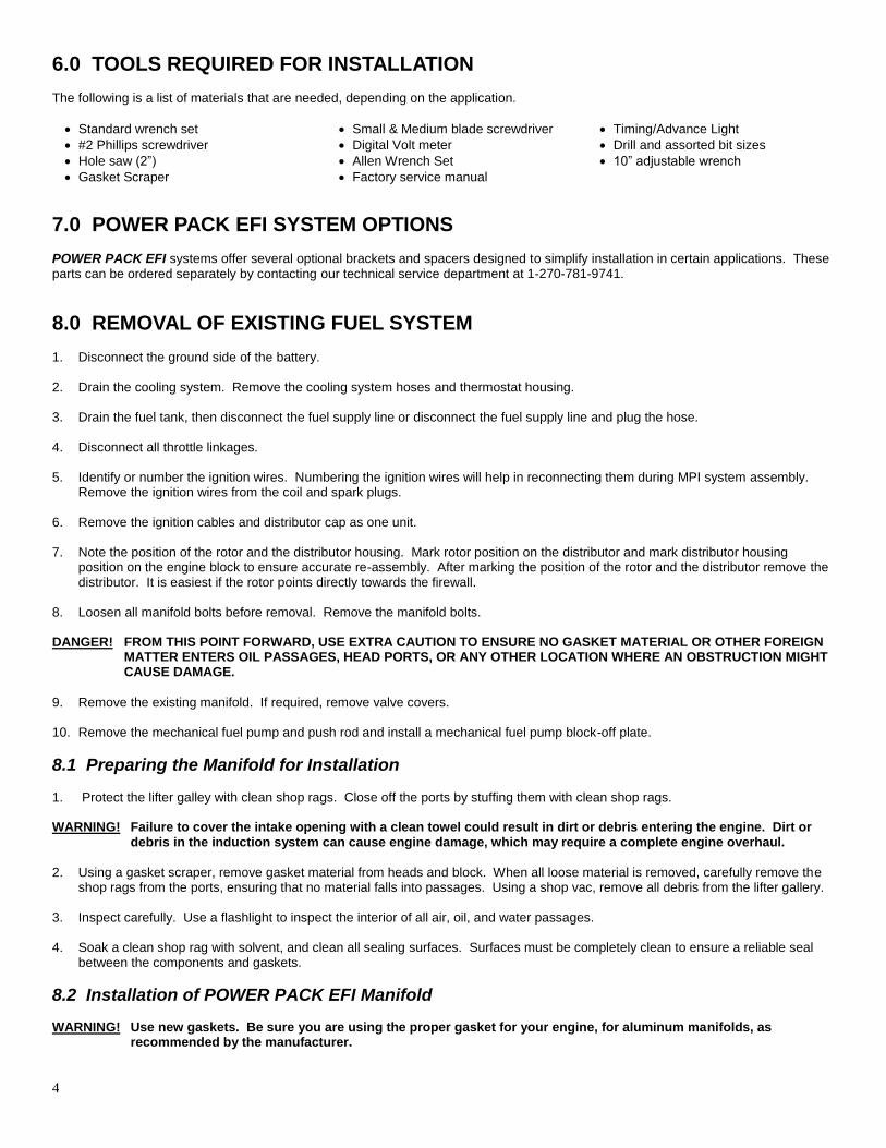
6.0 TOOLS REQUIRED FOR INSTALLATION The following is a list of materials that are needed, depending on the application.
Standard wrench set Small & Medium blade screwdriver Timing/Advance Light
#2 Phillips screwdriver Digital Volt meter Drill and assorted bit sizes
Hole saw (2”) Allen Wrench Set 10” adjustable wrench
Gasket Scraper Factory service manual
7.0 POWER PACK EFI SYSTEM OPTIONS POWER PACK EFI systems offer several optional brackets and spacers designed to simplify installation in certain applications. These parts can be ordered separately by contacting our technical service department at 1-270-781-9741.
8.0 REMOVAL OF EXISTING FUEL SYSTEM 1. Disconnect the ground side of the battery.
2. Drain the cooling system. Remove the cooling system hoses and thermostat housing.
3. Drain the fuel tank, then disconnect the fuel supply line or disconnect the fuel supply line and plug the hose.
4. Disconnect all throttle linkages.
5. Identify or number the ignition wires. Numbering the ignition wires will help in reconnecting them during MPI system assembly.
Remove the ignition wires from the coil and spark plugs.
6. Remove the ignition cables and distributor cap as one unit.
7. Note the position of the rotor and the distributor housing. Mark rotor position on the distributor and mark distributor housing position on the engine block to ensure accurate re-assembly. After marking the position of the rotor and the distributor remove the distributor. It is easiest if the rotor points directly towards the firewall.
8. Loosen all manifold bolts before removal. Remove the manifold bolts. DANGER! FROM THIS POINT FORWARD, USE EXTRA CAUTION TO ENSURE NO GASKET MATERIAL OR OTHER FOREIGN
MATTER ENTERS OIL PASSAGES, HEAD PORTS, OR ANY OTHER LOCATION WHERE AN OBSTRUCTION MIGHT CAUSE DAMAGE.
9. Remove the existing manifold. If required, remove valve covers.
10. Remove the mechanical fuel pump and push rod and install a mechanical fuel pump block-off plate.
8.1 Preparing the Manifold for Installation 1. Protect the lifter galley with clean shop rags. Close off the ports by stuffing them with clean shop rags.
WARNING! Failure to cover the intake opening with a clean towel could result in dirt or debris entering the engine. Dirt or
debris in the induction system can cause engine damage, which may require a complete engine overhaul.
2. Using a gasket scraper, remove gasket material from heads and block. When all loose material is removed, carefully remove the
shop rags from the ports, ensuring that no material falls into passages. Using a shop vac, remove all debris from the lifter gallery.
3. Inspect carefully. Use a flashlight to inspect the interior of all air, oil, and water passages.
4. Soak a clean shop rag with solvent, and clean all sealing surfaces. Surfaces must be completely clean to ensure a reliable seal between the components and gaskets.
8.2 Installation of POWER PACK EFI Manifold WARNING! Use new gaskets. Be sure you are using the proper gasket for your engine, for aluminum manifolds, as
recommended by the manufacturer.
5
1. The manifold comes with the rails, fittings, and crossovers loosely installed in the proper locations. The crossover lines will have to be removed in order to install the intake manifold bolts. The injectors, fittings, rails, and crossovers should be assembled and tightened after the manifold is installed on the engine.
2. Install the manifold gaskets, carefully following the instructions provided by the gasket manufacturer.
3. Use O2 sensor compatible RTV (again following manufacturer's instructions) around all water passages and for end seals if end seal gaskets are not used.
4. Carefully position the manifold on the heads, so the bolt holes in the manifold are centered over bolt hoses in the heads.
5. Hand start all the bolts.
6. Tighten down the manifold bolts in the proper sequence and torque as recommended in the engine manual.
NOTE: Consult your engine manual for proper fastener torque, bolt tightening pattern and other manifold installation specifications.
NOTE: POWER PACK Systems DO NOT include injectors. For injector recommendations, please see Appendix 1.
7. Remove the fuel rails. Install the fuel injectors. Lubricate the fuel injector top and bottom O-rings. Do not use synthetic, animal or
vegetable oils. Use of an O-ring specific lubricant is recommended. Use motor oil if you do not have a good O-ring lubricant. Be careful not to damage the O-rings.
WARNING! Damage of the O-ring can cause fuel leakage. A fuel leak may result in a fire or an explosion hazard, which could cause serious injury or death.
8. Carefully install the injectors into the rails and then install the injectors and both rails into the manifold. Reinstall the four 1/4-20 x
1” Allen head screws that held the rails in place and tighten securely.
9. Make sure that the four end fittings in the fuel rails (they should already be installed but not tightened) are threaded in to an adequate depth.
10. Reattach the front and rear crossover tubes. Tighten completely hand tight.
11. After the crossover tubes are installed, tighten the nut on the four fittings that go into the fuel rails. Tighten securely. 12. Securely tighten the front and rear crossover tubes with a wrench. 13. The regulator should already be installed. Make sure that the two Allen head screws securing it to the fuel rail are tight. Also
check that the regulator fitting it tight and is pointed in the desired direction. Do not overtighten the fitting in the regulator or it will leak.
Figure 1
6
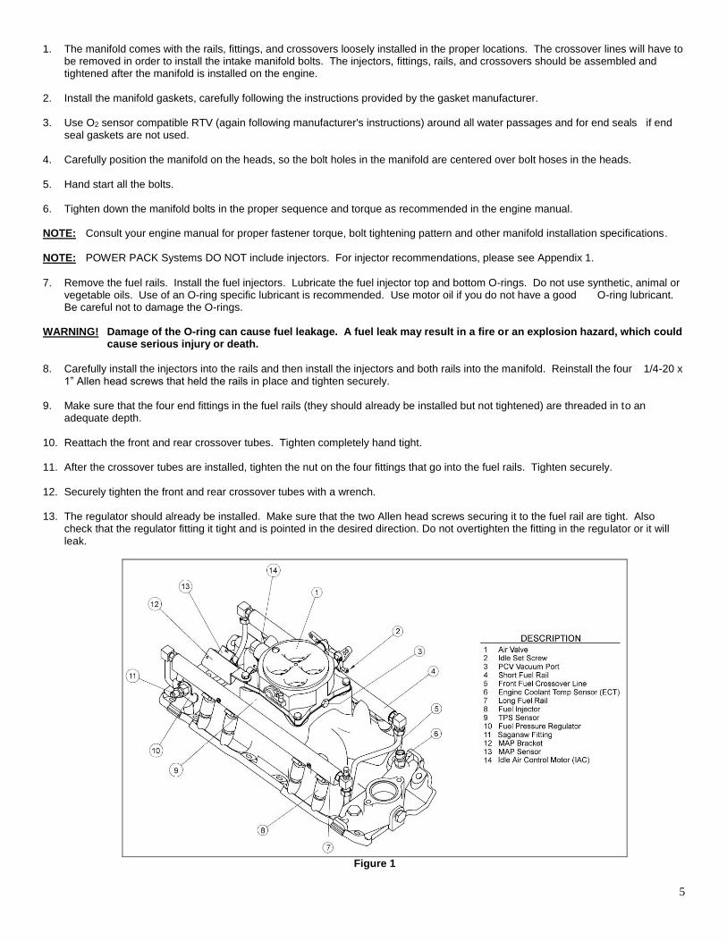
14. Next install the throttle body. The throttle body is in a separate box in the kit, which contains the gaskets needed. First install the gasket that matches the manifold base. Next install the steel plate included with the throttle body. Next install the gasket that matches the plate. Install the throttle body with the 4 5/16-18 bolts and washers included. The MAP sensor bracket is attached by the rear, passenger side bolt. Install the MAP sensor first with the two 10-32 x 1” screws and #10 washers. See Figure 1. The
throttle cable bracket is attached with the rear driver’s side bolt. The bracket in the kit works with most throttle cables and transmission cables.
15. Tighten throttle body bolts securely.
16. Check the front fuel rail cross over tubing. This line may shift during the foregoing operations, so ensure that the line cannot
interfere against the manifold runner or the water cross-over. Adjust if necessary.
17. Install new thermostat housing gasket, replace thermostat housing, replace the coolant hoses and refill the cooling system.
18. Attach the throttle cable.
8.3 Installing the distributor Follow the manufacturer’s recommended procedures for the following steps: 1. Drop in the distributor making sure that the rotor aligns with marks made during disassembly. If you are installing a new distributor,
you will have to make sure it is properly timed.
2. Align distributor housing with marks made on block during disassembly. 3. Ensure the distributor seats properly against manifold. 4. Ensure the distributor shaft is fully engaged in the oil pump.
5. Bolt the distributor hold down clamp to the manifold.
6. Replace the distributor cap.
7. Replace the spark plug wires and check that they are in the correct firing order.
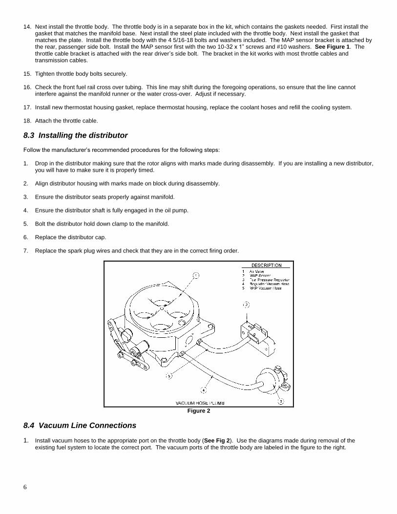
Figure 2
8.4 Vacuum Line Connections
1. Install vacuum hoses to the appropriate port on the throttle body (See Fig 2). Use the diagrams made during removal of the
existing fuel system to locate the correct port. The vacuum ports of the throttle body are labeled in the figure to the right.
7
9.0 SUPPLY AND RETURN FUEL SYSTEM INSTALLATION The MPI fuel system is a fuel metering system based on a time/pressure principle. The longer the injector is open the lager the amount of fuel per fueling event is delivered to the engine. Fuel pressure also plays a direct role in how much fuel is delivered to the engine. The higher the fuel pressure the more fuel is delivered during the fueling event. It is crucial for the proper operation of a high performance MPI system that the fuel system be installed and sized correctly. Unlike a carburetor where low-pressure fuel is delivered at an "as need" rate, the MPI supply system must continuously deliver fuel at the correct high pressure in a volume greater than the engine requires at maximum load. The excess fuel the injectors do not use is returned to the fuel tank. At idle, most of the fuel is returned to the tank, but a wide-open throttle (WOT) under full load nearly all of the fuel is used by the engine and only a small amount is returned to the fuel tank. An improperly installed or sized MPI supply fuel system may deliver enough fuel at low engine speeds but will starve the engine at WOT.
9.1 Fuel Supply/Return System Description NOTE: POWER PACK systems DO NOT include a fuel pump. The installer can select their own in-tank or in-line pump of choice.
Holley offers in-line and in-tank EFI fuel pumps. P/N 12-920 is an in-line pump rated for up to 600-650 HP naturally aspirated engines. It is the recommended in-line pump for Holley Multiport EFI systems for engines under 650 HP. Make sure the fuel pump flow is sufficient to support for the injector size selected.
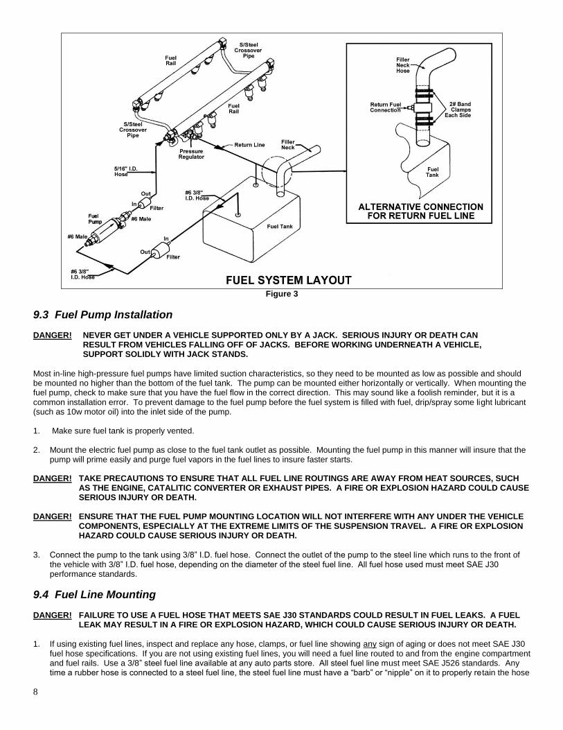
The high pressure fuel supply system consists of the following sub-systems: the fuel pick-up, a coarse fuel pump pre-filter, the high pressure electric fuel pump, the 10 micron high pressure fuel filter and a 3/8” ID fuel line (See Fig.3). The fuel pick-up delivers fuel from the tank to the inlet of the fuel pump filter. From the filter the fuel line supplies filtered fuel to the high pressure pump inlet. The high pressure electric fuel pump delivers pressurized fuel to the 10micron fuel filter, which in turn delivers filtered pressurized fuel to the fuel rails, fuel injectors, and the fuel pressure regulator. The function of the regulator is to maintain a constant fuel pressure of 300kPa (43.5psi). The outlet of the regulator returns the excess fuel back to the fuel tank. The following section covers the installation of an in-line pump such as Holley PN 12-920. If AN lines and fittings are used, obtain AN style filters. AN fittings are available for the 12-920 pump. PN 26-160 contains two -6 pump fittings and PN 26-180 contains two -8 pump fittings. All of the fittings on the intake manifold are -6 AN fittings (except the internal threads of the fuel pressure regulator which have a “Saginaw” thread. There are barbed adapters included that can be installed on the inlet and return fittings that can be used to connect to high pressure rated rubber fuel hose.
9.2 Fuel Pressure Regulator
The function of the fuel pressure regulator is to provide constant fuel pressure for the fuel injectors. Constant fuel pressure is essential to ensure an accurate fuel metering process. The fuel pressure regulator of the system is set to 300kPa (43.5 psi) to match the flow characteristics of the fuel injectors. The pressure regulator is reference to the manifold pressure to ensure the required differential pressure for the metering event. Thus at high manifold vacuum (i.e. idle) the fuel pressure gage will read a fuel pressure that is slightly lower than 300kPa (43.5 psi) because the gage is referenced to atmospheric conditions and not to the intake conditions. The pressure reading at idle will vary with the application as manifold vacuum changes from engine to engine and from application to application. The regulator included is adjustable. To adjust the fuel pressure: remove the vacuum reference line and turn the screw clockwise to increase the pressure (or counter-clockwise to decrease the fuel). Fuel pressure can be lowered slightly or raised to reduce or increase the amount of fuel the injectors add. This is usually only done when the injectors used need to have their flow decreased at idle or increased at wide-open throttle. Make sure you input the actual pressure into the software in the “Engine Parameters” section. NOTE: Increasing the fuel pressure by 10 PSI (43.5 to 53.5) results in a fuel metering increase of about 10%. The same is true when
reducing the fuel pressure. NOTE: If the fuel pressure is changed, make sure to change the “Actual System Pressure” in the Engine Parameters setup in the
software. DANGER! INCREASING THE FUEL PRESSURE BEYOND THE OPERATING POINT OF THE FUEL PUMP MAY RESULT IN
POOR ENGINE PERFORMANCE AND COULD CAUSE FUEL LEAKAGE ON COMPONENTS THAT ARE NOT RATED FOR EXCESSIVE HIGH FUEL PRESSURES. LEAKAGE OR BURSTING OF FUEL SYSTEM COMPONENTS MAY RESULT IN A FIRE OR EXPLOSION HAZARD, WHICH COULD CAUSE SERIOUS INJURY OR DEATH.
8
Figure 3
9.3 Fuel Pump Installation DANGER! NEVER GET UNDER A VEHICLE SUPPORTED ONLY BY A JACK. SERIOUS INJURY OR DEATH CAN RESULT FROM VEHICLES FALLING OFF OF JACKS. BEFORE WORKING UNDERNEATH A VEHICLE, SUPPORT SOLIDLY WITH JACK STANDS.
Most in-line high-pressure fuel pumps have limited suction characteristics, so they need to be mounted as low as possible and should be mounted no higher than the bottom of the fuel tank. The pump can be mounted either horizontally or vertically. When mounting the fuel pump, check to make sure that you have the fuel flow in the correct direction. This may sound like a foolish reminder, but it is a common installation error. To prevent damage to the fuel pump before the fuel system is filled with fuel, drip/spray some light lubricant (such as 10w motor oil) into the inlet side of the pump. 1. Make sure fuel tank is properly vented.
2. Mount the electric fuel pump as close to the fuel tank outlet as possible. Mounting the fuel pump in this manner will insure that the
pump will prime easily and purge fuel vapors in the fuel lines to insure faster starts.
DANGER! TAKE PRECAUTIONS TO ENSURE THAT ALL FUEL LINE ROUTINGS ARE AWAY FROM HEAT SOURCES, SUCH AS THE ENGINE, CATALITIC CONVERTER OR EXHAUST PIPES. A FIRE OR EXPLOSION HAZARD COULD CAUSE SERIOUS INJURY OR DEATH.
DANGER! ENSURE THAT THE FUEL PUMP MOUNTING LOCATION WILL NOT INTERFERE WITH ANY UNDER THE VEHICLE
COMPONENTS, ESPECIALLY AT THE EXTREME LIMITS OF THE SUSPENSION TRAVEL. A FIRE OR EXPLOSION HAZARD COULD CAUSE SERIOUS INJURY OR DEATH.
3. Connect the pump to the tank using 3/8” I.D. fuel hose. Connect the outlet of the pump to the steel line which runs to the front of
the vehicle with 3/8” I.D. fuel hose, depending on the diameter of the steel fuel line. All fuel hose used must meet SAE J30 performance standards.
9.4 Fuel Line Mounting DANGER! FAILURE TO USE A FUEL HOSE THAT MEETS SAE J30 STANDARDS COULD RESULT IN FUEL LEAKS. A FUEL
LEAK MAY RESULT IN A FIRE OR EXPLOSION HAZARD, WHICH COULD CAUSE SERIOUS INJURY OR DEATH.
1. If using existing fuel lines, inspect and replace any hose, clamps, or fuel line showing any sign of aging or does not meet SAE J30
fuel hose specifications. If you are not using existing fuel lines, you will need a fuel line routed to and from the engine compartment and fuel rails. Use a 3/8” steel fuel line available at any auto parts store. All steel fuel line must meet SAE J526 standards. Any time a rubber hose is connected to a steel fuel line, the steel fuel line must have a “barb” or “nipple” on it to properly retain the hose
9
(along with hose clamps). Either use the proper tool to put a “nipple” on the end of the tube (similar to the ends of the fuel filters), or use a compression fitting and a barded fitting adapter that is the proper size for the lines used. Clamping a rubber hose to a steel line that has the end squarely cut off does not ensure a safe connection.
DANGER! FAILURE TO USE STEEL FUEL LINE THAT MEETS SAE J526 STANDARDS COULD RESULT IN FUEL LEAKS. A
FUEL LEAK MAY RESULT IN A FIRE OR EXPLOSION HAZARD, WHICH COULD CAUSE SERIOUS INJURY OR DEATH.
DANGER! TAKE PRECAUTIONS TO ENSURE THAT ALL FUEL LINE ROUTINGS ARE AWAY FROM HEAT SOURCES, SUCH
AS THE ENGINE, CATALYTIC CONVERTER, OR EXHAUST PIPES. A FIRE OR EXPLOSION HAZARD COULD CAUSE SERIOUS INJURY OR DEATH.
DANGER! RIGID FUEL LINE TUBING SHOULD BE USED FOR UNDER VEHICLE RUNS, SUCH AS ALONG VEHICLE FRAME
RAILS OR UNDER FLOOR PANS. FAILURE TO DO SO IS A POTENTIAL FIRE OR EXPLOSION HAZARD, WHICH COULD CAUSE SERIOUS INJURY OR DEATH.
2. Anchor all fuel lines securely to solid chassis members at 1 ½ foot intervals using rubber coated steel clamps. Use of only
approved steel fuel line tubing will afford maximum fuel line protection against road hazards, gravel bombardment and premature wearing due to flexing, temperature extremes, road salt, weather, etc.
9.5 Fuel Filters WARNING! It is very important the fuel filters have the proper flow capacity, burst pressure rating and filter size. The flow
capacity of the filters must at least 60 gallons per hour (gph), and the filter size must be no bigger than 10 microns for the high fuel pressure filter and not bigger than 75 microns for the fuel pump inlet filter. The high-pressure fuel filter should be rated for at least for 150 psi burst pressure.
DANGER! FAILURE TO USE HIGH PRESSURE FUEL FILTER LINE RATED FOR A MINIMUM OF 100 PSI BURST PRESSURE
COULD RESULT IN FUEL LEAKS OR BURSTING OF THE FUEL FILTER. A FUEL LEAK MAY RESULT IN A FIRE OR EXPLOSION HAZARD, WHICH COULD CAUSE SERIOUS INJURY OR DEATH.
The fuel pump inlet filter must be plumbed between the fuel tank and the fuel pump. It should be mounted as close to the fuel tank as possible and should be mounted no higher than the top of the fuel tank. The high-pressure fuel filter should be plumbed between the fuel pump and the fuel rail. It should be mounted as close to the fuel rail as possible but should not be mounted above the fuel rail level. Be careful to ensure the suction part of the fuel system contains no air leaks. Air leaks are caused by holes and/or crevices so small that they will not leak fuel. Just because fuel is not leaking out does not mean air is not leaking in. Common causes of air leaks are not using thread sealing compound on fittings and cracks or holes in fuel lines. Air leaks could potentially cause fuel pump failure and or inadequate fuel supply to the fuel rails.
9.6 Return Line Installation DANGER! DO NOT USE THE VAPOR CANISTER LINES AS A FUEL RETURN LINE. POSSIBLE FUEL LEAKS MAY CREATE A
FIRE OR EXPLOSION HAZARD, CAUSING SERIOUS INJURY OR DEATH.
WARNING! Use only approved steel fuel line. The return fuel line should enter the fuel tank at the “fuel level sending unit
flange” or at the “filler neck”. The connection should be made below the flapper valve of the filler neck. The filler neck or sending unit must be removed from the tank to perform this operation.
DANGER! PROPER INSTALLATION OF THE FUEL RETURN LINE MAY REQUIRE THE COMPLETE REMOVAL OF THE FUEL
TANK. THIS WORK SHOULD BE DONE BY A FUEL TANK SPECIALIST, WHO REGULARLY DOES THIS WORK AND IS FAMILIAR WITH SAFETY REGULATIONS AND PRECAUTIONS NECESSARY TO DO THIS WORK. IF A PERSON ATTEMPTS THIS WORK WHO IS NOT FAMILIAR WITH THE SAFETY REGULATIONS AND PRECAUTIONS, AN EXPLOSION HAZARD MAY RESULT CAUSING SERIOUS INJURY OR DEATH.
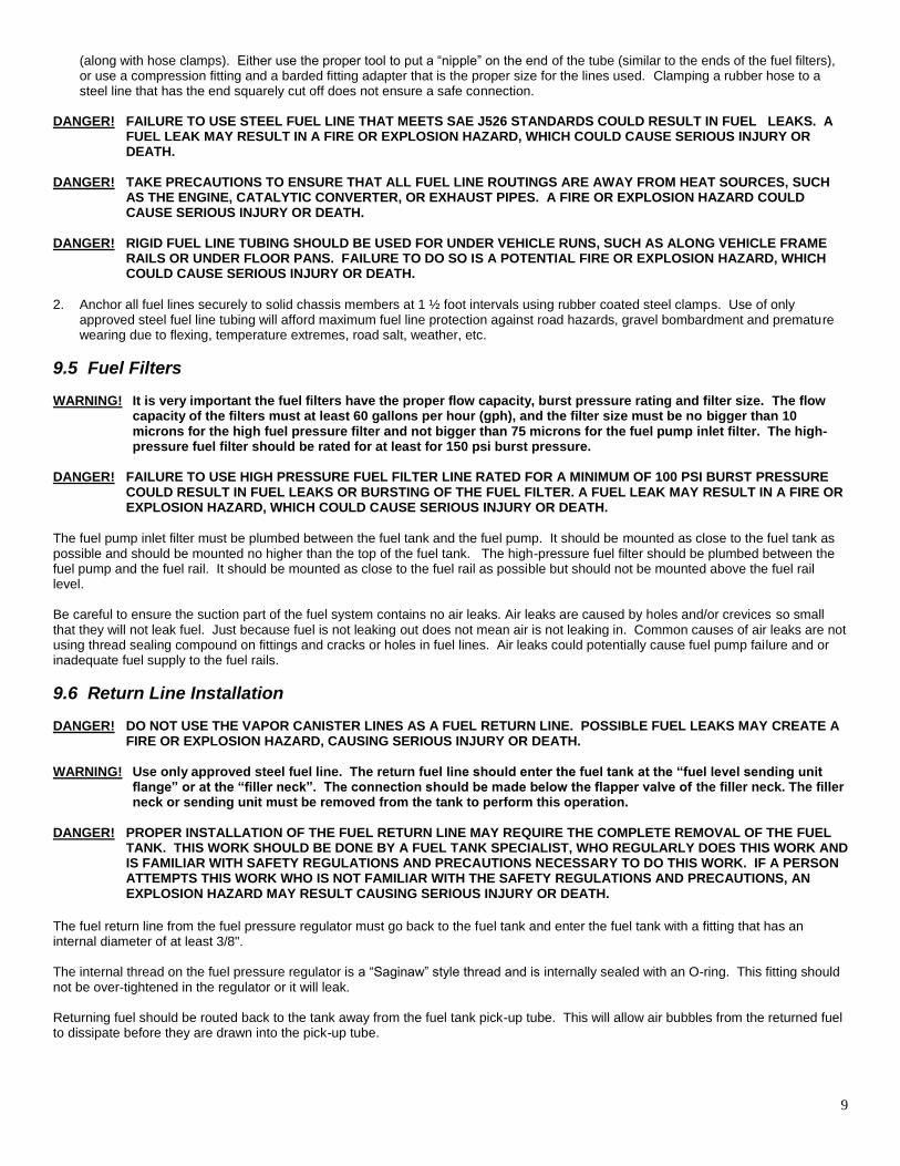
The fuel return line from the fuel pressure regulator must go back to the fuel tank and enter the fuel tank with a fitting that has an internal diameter of at least 3/8". The internal thread on the fuel pressure regulator is a “Saginaw” style thread and is internally sealed with an O-ring. This fitting should not be over-tightened in the regulator or it will leak. Returning fuel should be routed back to the tank away from the fuel tank pick-up tube. This will allow air bubbles from the returned fuel to dissipate before they are drawn into the pick-up tube.
10
Figure 4
There are several options including the following that meet the above criteria for returning the fuel to the fuel tank.
Use a fitting already in the fuel tank
Use the vent fitting. Be very careful not to block the fuel vapor from escaping the tank.
Route the return line into the filler neck. This can be done by cutting the filler neck, Inserting a welded "T" fitting, and securing the neck with multiple clamps.
Drill and weld a new fitting into the tank NOTICE: For best performance of your fuel supply system an in tank pump is recommended. Such an installation can be
achieved by either buying a late model fuel tank or have your tank modified by professional companies that install an in-tank pump with the required swirl pods and baffles.
DANGER! MODIFICATIONS TO FUEL TANKS SHOULD BE DONE BYFUEL TANK SPECIALISTS, WHO REGULARLY DO THIS
WORK AND ARE FAMILIAR WITH THE SAFETY REGULATIONS AND PRECAUTIONS NECESSARY. IF A PERSON ATTEMPTS THIS WORK WHO IS NOT FAMILIAR WITH THE SAFETY REGULATIONS AND PRECAUTIONS, AN EXPLOSION MAY RESULT CAUSING SERIOUS INJURY OR DEATH.
9.7 Oxygen Sensor Installation 9.7.1 Oxygen Sensor Mounting Procedure (not included) NOTE: Someone should install the oxygen sensor boss that has experience welding exhaust systems. Any competent exhaust shop
is able to perform this task at a minimal cost. WARNING! Use of leaded fuels will degrade the oxygen sensor over time and will result in incorrect exhaust gas oxygen-
content readings. WARNING! Use of some RTV silicone sealers will destroy the oxygen sensor used with this product. Ensure the RTV
silicone sealant you use is compatible with oxygen sensor vehicles. This information should be found on the RTV package.
1. Locate a position for the oxygen sensor as close to the engine as possible. If your vehicle has catalytic converters, the oxygen
sensor MUST be located between the engine and the catalytic converters. Good locations are in the drop pipe, or in the “”Y” pipe on single exhaust systems. Pick a location that allows easy installation of the oxygen sensor, but will protect the sensor from road hazards.
NOTE: Vehicles with open exhaust systems will require at least 18-20” of pipe after the sensor to eliminate false readings resulting
from atmospheric reversion. Even then, a false lean reading may occur at idle.
2. Drill a 7/8” hole in the location picked for the sensor. Weld the threaded boss into the 7/8” hole. An old spark plug with matching threads will avoid thread damage during the welding process. Weld all the way around the boss to insure a leak proof connection. Install the oxygen sensor into the threaded boss and tighten securely. It is a good idea to add anti-seize to the threads to aid in removal.
11
3. On vehicles equipped with an AIR pump, the oxygen sensor must be mounted before the AIR injection into the exhaust, or the AIR pump must be disconnected. Holley recommends that if the AIR is injected into both exhaust manifolds, mount the oxygen sensor into the pipe immediately after the exhaust manifold. Disconnect the AIR pump tube from the exhaust manifold and plug both ends. Check with local ordinances for the legality of this procedure in your area.
WARNING! Failure to disconnect the AIR pump or locating the oxygen sensor downstream from AIR injection will result in an
extremely rich mixture which could cause drivability problems and severe engine damage.
10.0 SENSOR WIRING NOTE: Holley offers a sensor connector kit that can be used with any harness – MPFI kits P/N 534-205 & Stealthram kits 534-213.
NOTE: The pin letters designated are the ones on the connector shell.
Throttle Position Sensor (TPS)
The Holley Throttle Body uses a three wire TPS. The following is the correct wiring hookup. Pin A – 5-volt input Pin B – Ground Pin C – Output Manifold Absolute Pressure Sensor (MAP)
The System comes with a 1 BAR MAP sensor. The following is the correct wiring hookup. Pin A – Ground Pin B – Output Pin C – 5-volt input
Air and Coolant Temperature Sensors The System comes with standard General Motor’s two-wire sensors. The sensors can be wired in either direction. Idle Air Control Motor (IAC)
The IAC Motor included is a Chrysler style. The motor contains two circuits that must be both connected properly. If the pins are reversed, the motor will either operate backwards, improperly, or will be damaged. Pins A and D are a circuit. Pins B and C are a circuit. To change from a GM style IAC to the Holley (Chrysler style) IAC, the following pins need to be changed: GM Connector Holley Connector A remains A B changes to D C changes to B D changes to C
11.0 MECHANICAL CHECKOUT BEFORE STARTING ENGINE Before starting engine, review and check off the following items: Are electrical connections correct? Are all fuel lines hooked up and correct? Is throttle linkage hooked up? Have fuel lines been leak checked? Are all vacuum hoses connected? Are all sensors installed and hooked up properly?
1. Reconnect the battery.
2. Make sure all relays and fuses are connected. 3. Make sure that there is no leakage from any fuel lines when the fuel system has been pressurized.
4. Ensure that all vacuum and port connections have been plugged or made. Now install the air cleaner.
12
DANGER! MOVE THE THROTTLE INTO LINKAGE INTO WIDE OPEN CONDITION AND CHECK THAT IT DOES NOT INTERFERE WITH AIR CLEANER OR OTHER COMPONENTS OF THE ENGINE AND MAKE SURE THAT IT RETURNS FREELY TO IDLE CONDITION WHEN RELEASED. THROTTLE RETURN ACTION CAN BE ENHANCED BY ADDING ADDITIONAL SPRINGS THAT PULL THE THROTTLE INTO CLOSED CONDITIONS. FAILURE OF TESTING THROTTLE ACTUATION PERFORMANCE MAY CAUSE UNSAFE DRIVING CONDITIONS, WHICH COULD CAUSE SERIOUS INJURY OR DEATH.
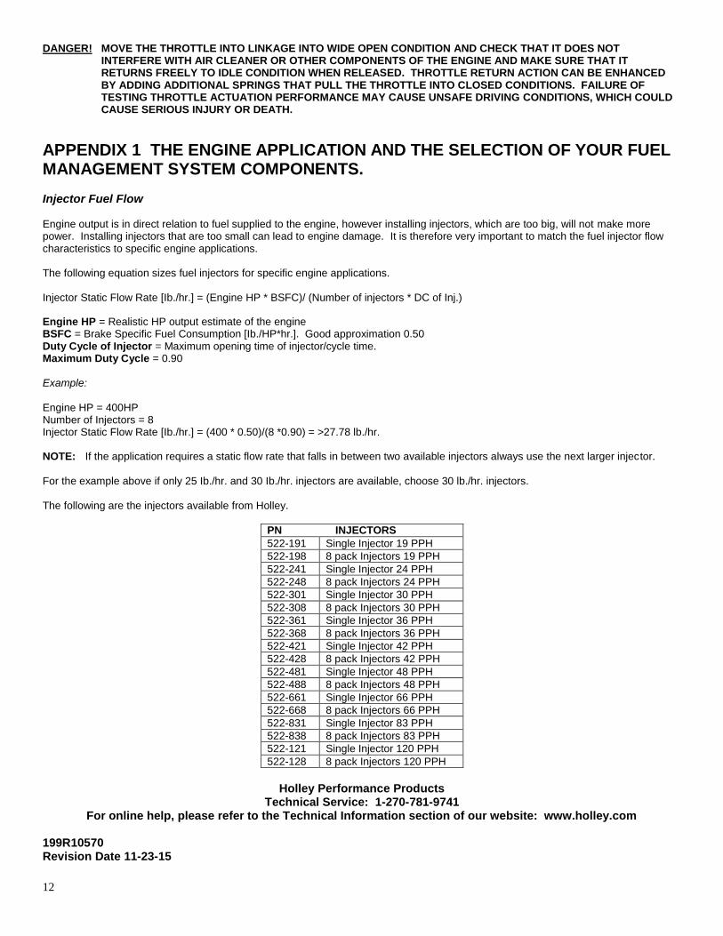
APPENDIX 1 THE ENGINE APPLICATION AND THE SELECTION OF YOUR FUEL MANAGEMENT SYSTEM COMPONENTS. Injector Fuel Flow Engine output is in direct relation to fuel supplied to the engine, however installing injectors, which are too big, will not make more power. Installing injectors that are too small can lead to engine damage. It is therefore very important to match the fuel injector flow characteristics to specific engine applications. The following equation sizes fuel injectors for specific engine applications. Injector Static Flow Rate [Ib./hr.] = (Engine HP * BSFC)/ (Number of injectors * DC of Inj.) Engine HP = Realistic HP output estimate of the engine BSFC = Brake Specific Fuel Consumption [Ib./HP*hr.]. Good approximation 0.50 Duty Cycle of Injector = Maximum opening time of injector/cycle time. Maximum Duty Cycle = 0.90
Example:
Engine HP = 400HP Number of Injectors = 8 Injector Static Flow Rate [Ib./hr.] = (400 * 0.50)/(8 *0.90) = >27.78 lb./hr. NOTE: If the application requires a static flow rate that falls in between two available injectors always use the next larger injector.
For the example above if only 25 Ib./hr. and 30 Ib./hr. injectors are available, choose 30 lb./hr. injectors. The following are the injectors available from Holley.
PN INJECTORS
522-191 Single Injector 19 PPH
522-198 8 pack Injectors 19 PPH
522-241 Single Injector 24 PPH
522-248 8 pack Injectors 24 PPH
522-301 Single Injector 30 PPH
522-308 8 pack Injectors 30 PPH
522-361 Single Injector 36 PPH
522-368 8 pack Injectors 36 PPH
522-421 Single Injector 42 PPH
522-428 8 pack Injectors 42 PPH
522-481 Single Injector 48 PPH
522-488 8 pack Injectors 48 PPH
522-661 Single Injector 66 PPH
522-668 8 pack Injectors 66 PPH
522-831 Single Injector 83 PPH
522-838 8 pack Injectors 83 PPH
522-121 Single Injector 120 PPH
522-128 8 pack Injectors 120 PPH
Holley Performance Products
Technical Service: 1-270-781-9741 For online help, please refer to the Technical Information section of our website: www.holley.com
199R10570 Revision Date 11-23-15