Embed Size (px)
Citation preview
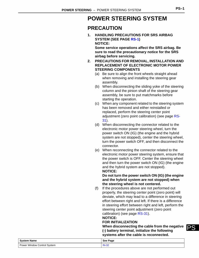
POWER STEERING – POWER STEERING SYSTEM PS–1
PS
POWER STEERING SYSTEMPRECAUTION1. HANDLING PRECAUTIONS FOR SRS AIRBAG
SYSTEM (SEE PAGE RS-1)NOTICE:Some service operations affect the SRS airbag. Be sure to read the precautionary notice for the SRS airbag before servicing.
2. PRECAUTIONS FOR REMOVAL, INSTALLATION AND REPLACEMENT OF ELECTRONIC MOTOR POWER STEERING COMPONENTS(a) Be sure to align the front wheels straight ahead
when removing and installing the steering gear assembly.
(b) When disconnecting the sliding yoke of the steering column and the pinion shaft of the steering gear assembly, be sure to put matchmarks before starting the operation.
(c) When any component related to the steering system has been removed and either reinstalled or replaced, perform the steering center point adjustment (zero point calibration) (see page RS-31).
(d) When disconnecting the connector related to the electronic motor power steering wheel, turn the power switch ON (IG) (the engine and the hybrid system are not stopped), center the steering wheel, turn the power switch OFF, and then disconnect the connector.
(e) When reconnecting the connector related to the electronic motor power steering system, ensure that the power switch is OFF. Center the steering wheel and then turn the power switch ON (IG) (the engine and the hybrid system are not stopped).NOTICE:Do not turn the power switch ON (IG) (the engine and the hybrid system are not stopped) when the steering wheel is not centered.
(f) If the procedures above are not performed out properly, the steering center point (zero point) will deviate, which may lead to a difference in steering effort between right and left. If there is a difference in steering effort between right and left, perform the steering center point adjustment (zero point calibration) (see page RS-31).NOTICE:FOR INITIALIZATIONWhen disconnecting the cable from the negative (-) battery terminal, initialize the following systems after the cable is reconnected.
System Name See Page
Power Window Control System IN-32
PS–2 POWER STEERING – POWER STEERING SYSTEM
PS
NOTICE:FOR HYBRID SYSTEM ACTIVATION• When the warning light is illuminated or the
battery has been disconnected and reconnected, pressing the power switch may not start the system on the first try. If so, press the power switch again.
• With the power switch's power mode changed to ON (IG), disconnect the battery. If the key is not in the key slot during reconnection, DTC B2799 may be output.
POWER STEERING – POWER STEERING SYSTEM PS–3
PS
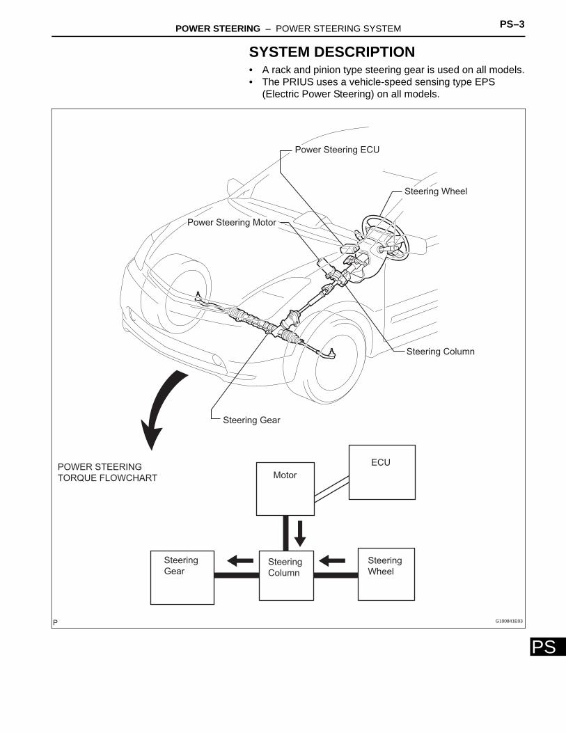
SYSTEM DESCRIPTION• A rack and pinion type steering gear is used on all models.• The PRIUS uses a vehicle-speed sensing type EPS
(Electric Power Steering) on all models.
Power Steering ECU
Steering Wheel
Power Steering Motor
Steering Column
Steering Gear
ECU
Motor
Steering
WheelSteering
Column
Steering
Gear
POWER STEERING
TORQUE FLOWCHART
G100841E03
PS–4 POWER STEERING – POWER STEERING SYSTEM
PS
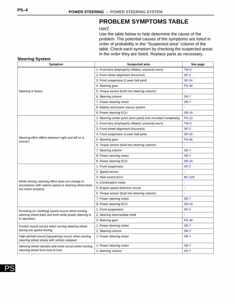
PROBLEM SYMPTOMS TABLEHINT:Use the table below to help determine the cause of the problem. The potential causes of the symptoms are listed in order of probability in the "Suspected area" column of the table. Check each symptom by checking the suspected areas in the order they are listed. Replace parts as necessary.
Steering SystemSymptom Suspected area See page
Steering is heavy.
1. Front tires (improperly inflated, unevenly worn) TW-3
2. Front wheel alignment (Incorrect) SP-2
3. Front suspension (Lower ball joint) SP-24
4. Steering gear PS-49
5. Torque sensor (built into steering column) -
6. Steering column SR-7
7. Power steering motor SR-7
8. Battery and power source system -
9. Power steering ECU SR-16
Steering effort differs between right and left or is uneven.
1. Steering center point (zero point) (not recorded completely) PS-13
2. Front tires (improperly inflated, unevenly worn) TW-3
3. Front wheel alignment (Incorrect) SP-2
4. Front suspension (Lower ball joint) SP-23
5. Steering gear PS-49
6. Torque sensor (built into steering column) -
7. Steering column SR-7
8. Power steering motor SR-7
9. Power steering ECU SR-16
While driving, steering effort does not change in accordance with vehicle speed or steering wheel does not return properly.
1. Front suspension SP-2
2. Speed sensor -
3. Skid control ECU BC-229
4. Combination meter -
5. Engine speed detection circuit -
6. Torque sensor (built into steering column) -
7. Power steering motor SR-7
8. Power steering ECU SR-16
Knocking (or clunking) sound occurs when turning steering wheel back and forth while power steering is in operation.
1. Front suspension SP-2
2. Steering intermediate shaft -
3. Steering gear PS-49
Friction sound occurs when turning steering wheel during low speed driving.
1. Power steering motor SR-7
2. Steering column SR-7
High-pitched sound (squeaking) occurs when turning steering wheel slowly with vehicle stopped.
1. Power steering motor SR-7
Steering wheel vibrates and noise occurs when turning steering wheel from lock to lock.
1. Power steering motor SR-7
2. Steering column SR-7
POWER STEERING – POWER STEERING SYSTEM PS–5
PS
ON-VEHICLE INSPECTION1. CHECK STEERING EFFORT (TORQUE)
NOTICE:Some service operations affect the SRS airbag. Be sure to read the precautionary notice for the SRS airbag before servicing.(a) Stop the vehicle on a level, paved road and align the
wheels straight ahead.(b) Disconnect the cable from the negative (-) battery
terminal.(c) Remove the steering pad (see page RS-267).(d) Connect the cable to the negative (-) battery
terminal.(e) Using a torque wrench, check if the steering wheel
set nut is properly tightened.Torque: 50 N*m (510 kgf*cm, 37 ft.*lbf)
(f) Turn the power switch ON (IG) (the engine and the hybrid system are not operated) so that power steering is ready to operate.
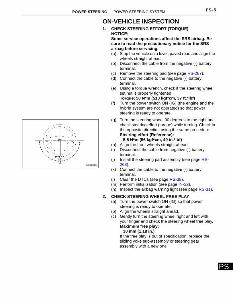
(g) Turn the steering wheel 90 degrees to the right and check steering effort (torque) while turning. Check in the opposite direction using the same procedure.Steering effort (Reference):
5.5 N*m (56 kgf*cm, 49 in.*lbf)(h) Align the front wheels straight ahead.(i) Disconnect the cable from negative (-) battery
terminal.(j) Install the steering pad assembly (see page RS-
268).(k) Connect the cable to the negative (-) battery
terminal.(l) Clear the DTCs (see page RS-38).(m) Perform initialization (see page IN-32).(n) Inspect the airbag warning light (see page RS-31).
2. CHECK STEERING WHEEL FREE PLAY(a) Turn the power switch ON (IG) so that power
steering is ready to operate.(b) Align the wheels straight ahead.(c) Gently turn the steering wheel right and left with
your finger and check the steering wheel free play.Maximum free play:
30 mm (1.18 in.)If the free play is out of specification, replace the sliding yoke sub-assembly or steering gear assembly with a new one.
G029440E02
PS–6 POWER STEERING – ELECTRONIC POWER STEERING SYSTEM
PS
ELECTRONIC POWER STEERING SYSTEMPRECAUTION1. FOR INITIALIZATION
NOTICE:When disconnecting the cable from the negative (-) battery terminal, initialize the following systems after the cable is reconnected.
2. FOR HYBRID SYSTEM ACTIVATIONNOTICE:• When the warning light is illuminated or the battery
has been disconnected and reconnected, pressing the power switch may not start the system on the first try. If so, press the power switch again.
• With the power switch's power mode changed to ON (IG), disconnect the battery. If the key is not in the key slot during reconnection, DTC B2799 may be output.
3. HANDLING PRECAUTIONS(a) When handling the electronic parts:
(1) Avoid any impact to electronic parts such as ECUs and relays. Replace the parts with new ones if dropped or subjected to a severe impact.
(2) Do not expose any electronic parts to high temperature and humidity.
(3) Do not touch the connector terminals in order to prevent deformation or malfunctions due to static electricity.
(4) When the power steering ECU has been replaced with a new one, perform the torque sensor zero point calibration (see page PS-13).
(b) When handling the steering column:(1) Avoid any impact to the steering column,
especially to the motor or torque sensor. Replace the parts with new ones if dropped or subjected to a severe impact.
(2) Do not pull on the wire harness when moving the steering column.
(3) When the steering column has been replaced, perform the torque sensor zero point calibration after initializing the torque sensor zero point calibration signal (see page PS-13).
(c) When disconnecting and reconnecting the connectors:(1) When disconnecting a connector related to the
electric power steering system, turn the power switch ON (IG), center the steering wheel, turn the power switch OFF, and then disconnect the connector.
System Name See procedure
Power Window Control System IN-32
POWER STEERING – ELECTRONIC POWER STEERING SYSTEM PS–7
PS
(2) When reconnecting a connector related to the electric power steering system, ensure that the power switch is OFF. Center the steering wheel and then turn the power switch ON (IG).NOTICE:Do not turn the power switch ON (IG) when the steering wheel is not centered.
(3) If the above operations are not carried out properly, the steering center point (zero point) will deviate, which may lead to a difference in right and left steering effort. If there is a difference in right and left steering effort, perform the torque sensor zero point calibration (see page PS-13).
4. PRECAUTIONS FOR CAN COMMUNICATION(a) CAN communication is used to receive information
from the skid control ECU and to transmit warnings to the meter and the multi-display. When there are any problems in the CAN communication lines, DTCs indicating the communication line malfunctions are output.
(b) Perform troubleshooting for the communication line problems when the CAN communication DTCs are output. Be sure to start troubleshooting on the electronic power steering system when data communication is normal.
(c) A temporary fix or repair with bypass wiring, etc. is impossible because the length and path of each CAN communication line is specific.
PS–8 POWER STEERING – ELECTRONIC POWER STEERING SYSTEM
PS
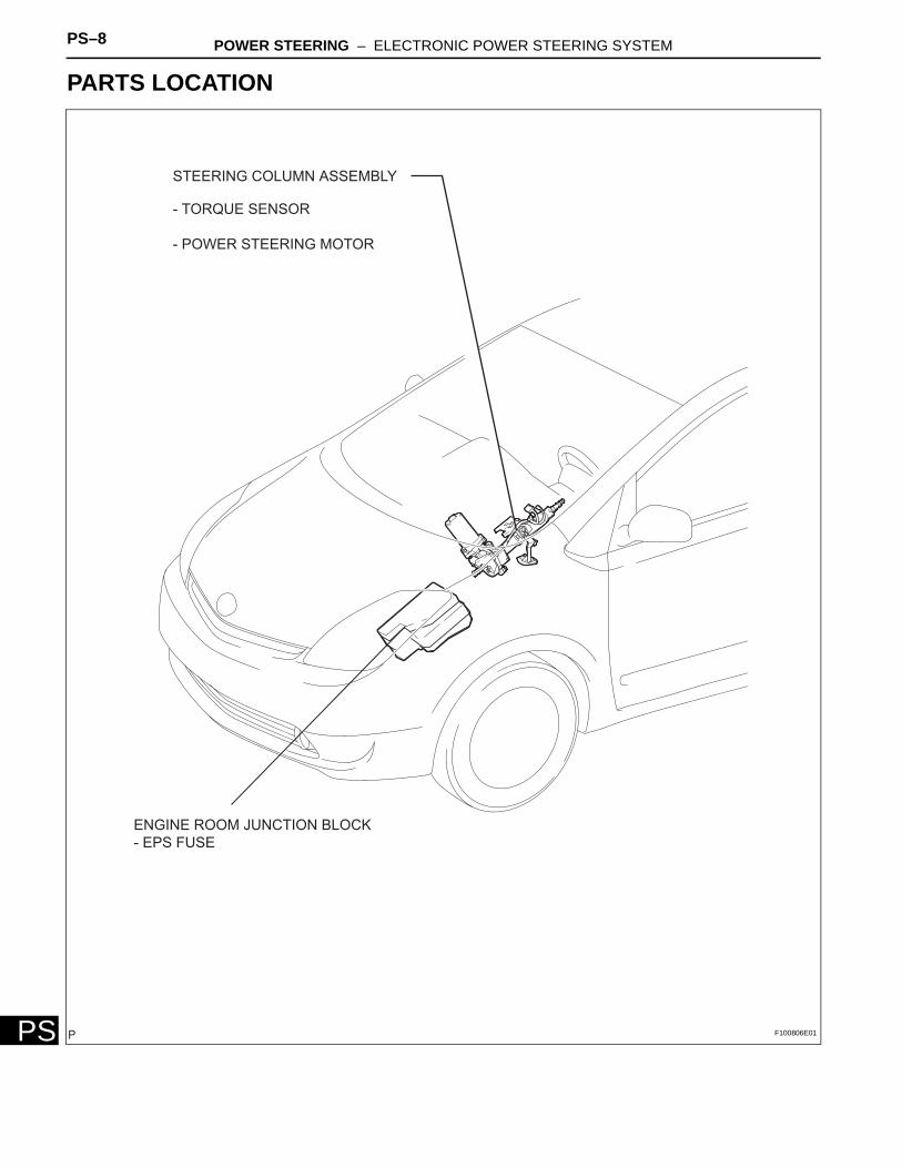
PARTS LOCATION
ENGINE ROOM JUNCTION BLOCK
- EPS FUSE
STEERING COLUMN ASSEMBLY
- TORQUE SENSOR
- POWER STEERING MOTOR
F100806E01
POWER STEERING – ELECTRONIC POWER STEERING SYSTEM PS–9
PS
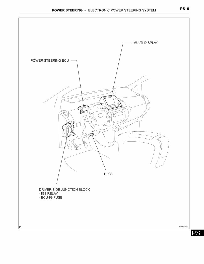
POWER STEERING ECU
MULTI-DISPLAY
DRIVER SIDE JUNCTION BLOCK
- IG1 RELAY
- ECU-IG FUSE
DLC3
F100807E01
PS–10 POWER STEERING – ELECTRONIC POWER STEERING SYSTEM
PS
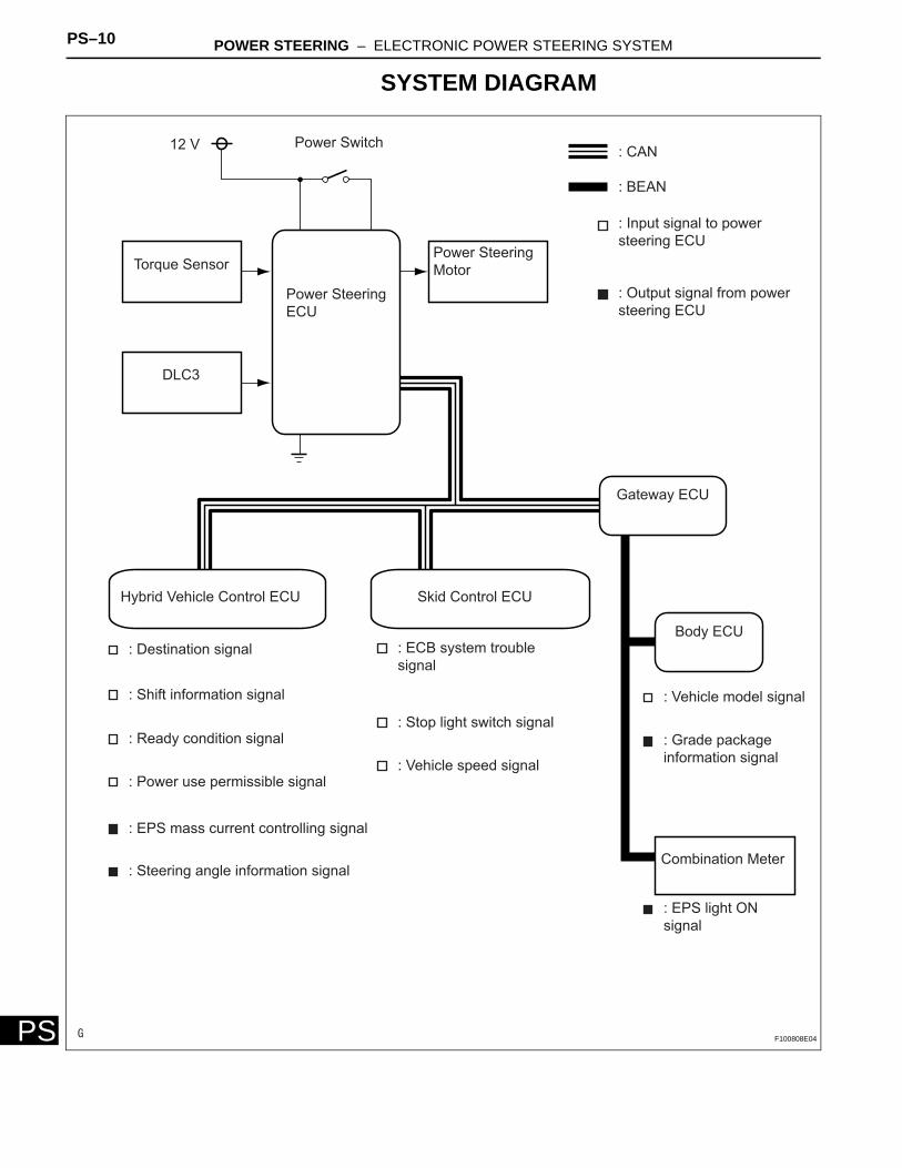
SYSTEM DIAGRAM
12 V Power Switch
Power Steering
Motor
Power Steering
ECU
Torque Sensor
DLC3
: CAN
: BEAN
: Input signal to power
steering ECU
: Output signal from power
steering ECU
: Vehicle model signal
: Grade package
information signal
: Destination signal
: Shift information signal
: Ready condition signal
: Power use permissible signal
: ECB system trouble
signal
: Stop light switch signal
: Vehicle speed signal
: EPS mass current controlling signal
: Steering angle information signal
: EPS light ON
signal
Hybrid Vehicle Control ECU Skid Control ECU
Gateway ECU
Body ECU
Combination Meter
F100808E04
POWER STEERING – ELECTRONIC POWER STEERING SYSTEM PS–11
PS
SYSTEM DESCRIPTION1. DESCRIPTION
(a) The electronic power steering system generates torque through the operation of the motor and the reduction gear installed on the column shaft in order to assist steering effort.Directions and amount of assisting power are determined by signals from the torque sensor built into the steering column assembly and by the power steering ECU, and controlled in accordance with vehicle speed. As a result, steering effort is controlled to be light during low speed driving and moderately high during high speed driving.(1) Power steering ECU:
The power steering ECU calculates assisting power based on a steering torque signal from the torque sensor and a vehicle speed signal from the skid control ECU. It generates specified assisting torque by controlling current to the motor.
(2) Torque sensor:The torque sensor detects steering effort generated when the steering wheel is turned and converts it to an electrical signal.
(3) Power steering motor:The power steering motor is activated by the current from the power steering ECU and generates torque to assist steering effort.
PS–12 POWER STEERING – ELECTRONIC POWER STEERING SYSTEM
PS
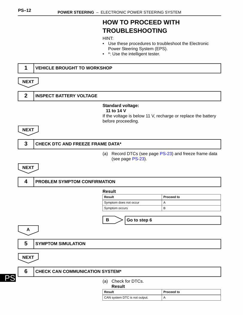
HOW TO PROCEED WITH TROUBLESHOOTINGHINT:• Use these procedures to troubleshoot the Electronic
Power Steering System (EPS).• *: Use the intelligent tester.
NEXT
Standard voltage:11 to 14 V
If the voltage is below 11 V, recharge or replace the battery before proceeding.
NEXT
(a) Record DTCs (see page PS-23) and freeze frame data (see page PS-23).
NEXT
Result
B
A
NEXT
(a) Check for DTCs.Result
1 VEHICLE BROUGHT TO WORKSHOP
2 INSPECT BATTERY VOLTAGE
3 CHECK DTC AND FREEZE FRAME DATA*
4 PROBLEM SYMPTOM CONFIRMATION
Result Proceed to
Symptom does not occur A
Symptom occurs B
Go to step 6
5 SYMPTOM SIMULATION
6 CHECK CAN COMMUNICATION SYSTEM*
Result Proceed to
CAN system DTC is not output. A
POWER STEERING – ELECTRONIC POWER STEERING SYSTEM PS–13
PS
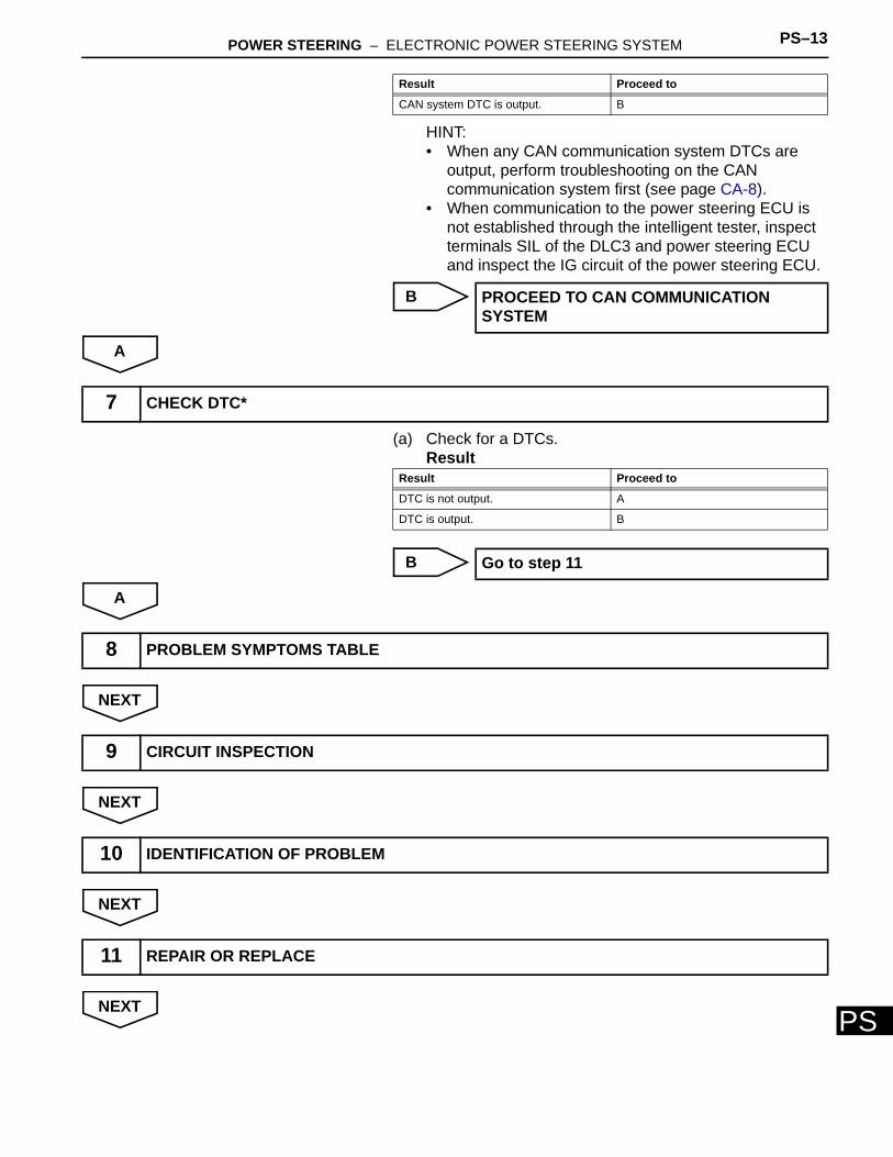
HINT:• When any CAN communication system DTCs are
output, perform troubleshooting on the CAN communication system first (see page CA-8).
• When communication to the power steering ECU is not established through the intelligent tester, inspect terminals SIL of the DLC3 and power steering ECU and inspect the IG circuit of the power steering ECU.
B
A
(a) Check for a DTCs.Result
B
A
NEXT
NEXT
NEXT
NEXT
CAN system DTC is output. B
PROCEED TO CAN COMMUNICATION SYSTEM
Result Proceed to
7 CHECK DTC*
Result Proceed to
DTC is not output. A
DTC is output. B
Go to step 11
8 PROBLEM SYMPTOMS TABLE
9 CIRCUIT INSPECTION
10 IDENTIFICATION OF PROBLEM
11 REPAIR OR REPLACE
PS–14 POWER STEERING – ELECTRONIC POWER STEERING SYSTEM
PS
NEXT
12 CONFIRMATION TEST
END
POWER STEERING – ELECTRONIC POWER STEERING SYSTEM PS–15
PS
CALIBRATION1. INITIALIZATION OF TORQUE SENSOR ZERO POINT
CALIBRATION SIGNALNOTICE:Under the following conditions, perform the torque sensor zero point calibration after initializing the torque sensor zero point calibration signal in the ECU:• The steering column (containing the torque
sensor) has been replaced.• The power steering ECU has been replaced.• The steering wheel has been replaced.• The steering gear assembly has been replaced.• There is a difference in right and left steering
effort.(a) Center the steering wheel and align the front wheels
straight ahead.(b) Connect the intelligent tester (with CAN VIM) to the
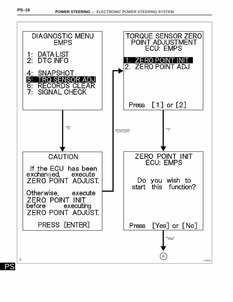
DLC3.(c) Turn the power switch ON (IG) and then initialize the
torque sensor zero point calibration signal by following the directions on the tester screen.NOTICE:Do not turn the steering wheel while initializing the zero point calibration signal.
(d) Perform steering zero point calibration after turning the power switch OFF.NOTICE:Zero point calibration cannot be carried out with the power switch ON (IG) after initialization of the zero point calibration signal is completed.
PS–16 POWER STEERING – ELECTRONIC POWER STEERING SYSTEM
PSF100818

POWER STEERING – ELECTRONIC POWER STEERING SYSTEM PS–17
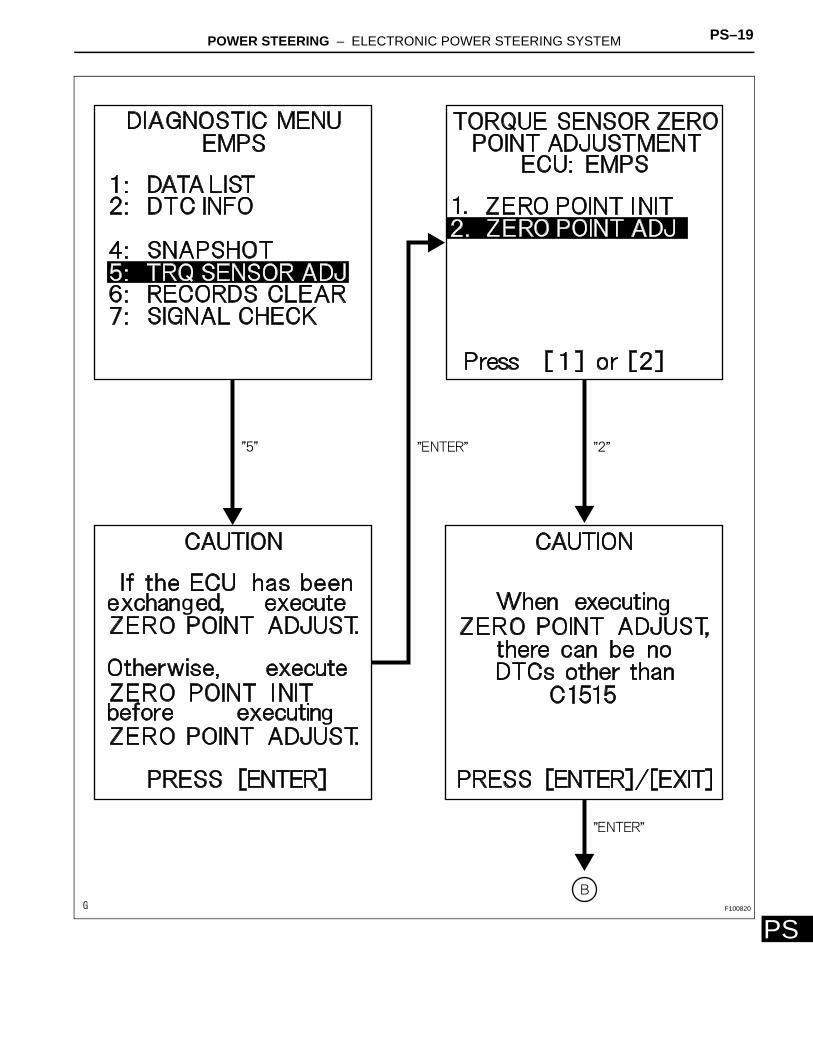
PS2. TORQUE SENSOR ZERO POINT CALIBRATION(a) Center the steering wheel and align the front wheels
straight ahead.(b) Connect the intelligent tester (with CAN VIM) to the
DLC3.
F100819
PS–18 POWER STEERING – ELECTRONIC POWER STEERING SYSTEM
PS
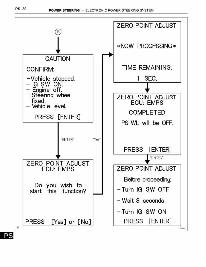
(c) Turn the power switch ON (IG) and then perform the zero point calibration by following the directions on the tester screen.NOTICE:• The vehicle is stopped.• Do not start the engine. (Do not turn the
power switch ON (READY).)• Do not turn the steering wheel.• The vehicle is on level ground.
(d) Confirm that no DTCs are output after completing the operation.(1) When DTC C1515 is output, refer to the
following procedures (see page PS-32).(2) When DTC C1516 is output, refer to the
following procedures (see page PS-33).(3) When DTC C1534 is output, refer to the
following procedures (see page PS-36).
POWER STEERING – ELECTRONIC POWER STEERING SYSTEM PS–19
PSF100820
PS–20 POWER STEERING – ELECTRONIC POWER STEERING SYSTEM
PSF100821
POWER STEERING – ELECTRONIC POWER STEERING SYSTEM PS–21
PS
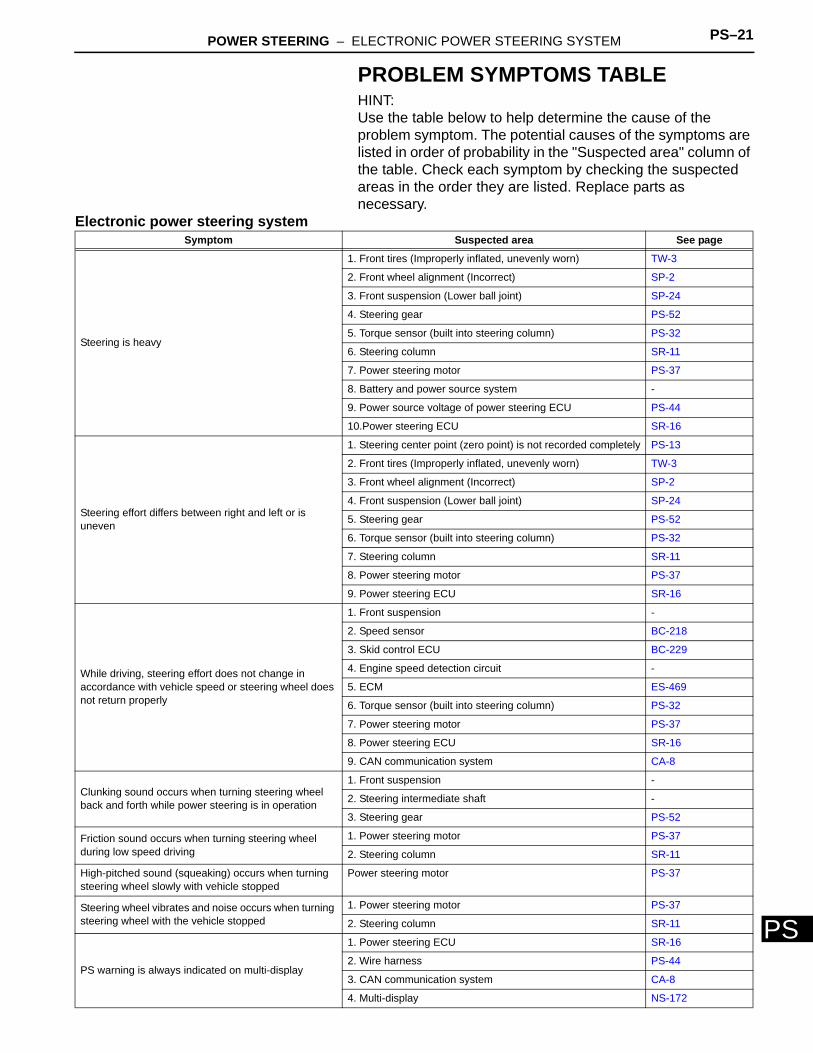
PROBLEM SYMPTOMS TABLEHINT:Use the table below to help determine the cause of the problem symptom. The potential causes of the symptoms are listed in order of probability in the "Suspected area" column of the table. Check each symptom by checking the suspected areas in the order they are listed. Replace parts as necessary.
Electronic power steering systemSymptom Suspected area See page
Steering is heavy
1. Front tires (Improperly inflated, unevenly worn) TW-3
2. Front wheel alignment (Incorrect) SP-2
3. Front suspension (Lower ball joint) SP-24
4. Steering gear PS-52
5. Torque sensor (built into steering column) PS-32
6. Steering column SR-11
7. Power steering motor PS-37
8. Battery and power source system -
9. Power source voltage of power steering ECU PS-44
10.Power steering ECU SR-16
Steering effort differs between right and left or is uneven
1. Steering center point (zero point) is not recorded completely PS-13
2. Front tires (Improperly inflated, unevenly worn) TW-3
3. Front wheel alignment (Incorrect) SP-2
4. Front suspension (Lower ball joint) SP-24
5. Steering gear PS-52
6. Torque sensor (built into steering column) PS-32
7. Steering column SR-11
8. Power steering motor PS-37
9. Power steering ECU SR-16
While driving, steering effort does not change in accordance with vehicle speed or steering wheel does not return properly
1. Front suspension -
2. Speed sensor BC-218
3. Skid control ECU BC-229
4. Engine speed detection circuit -
5. ECM ES-469
6. Torque sensor (built into steering column) PS-32
7. Power steering motor PS-37
8. Power steering ECU SR-16
9. CAN communication system CA-8
Clunking sound occurs when turning steering wheel back and forth while power steering is in operation
1. Front suspension -
2. Steering intermediate shaft -
3. Steering gear PS-52
Friction sound occurs when turning steering wheel during low speed driving
1. Power steering motor PS-37
2. Steering column SR-11
High-pitched sound (squeaking) occurs when turning steering wheel slowly with vehicle stopped
Power steering motor PS-37
Steering wheel vibrates and noise occurs when turning steering wheel with the vehicle stopped
1. Power steering motor PS-37
2. Steering column SR-11
PS warning is always indicated on multi-display
1. Power steering ECU SR-16
2. Wire harness PS-44
3. CAN communication system CA-8
4. Multi-display NS-172
PS–22 POWER STEERING – ELECTRONIC POWER STEERING SYSTEM
PS
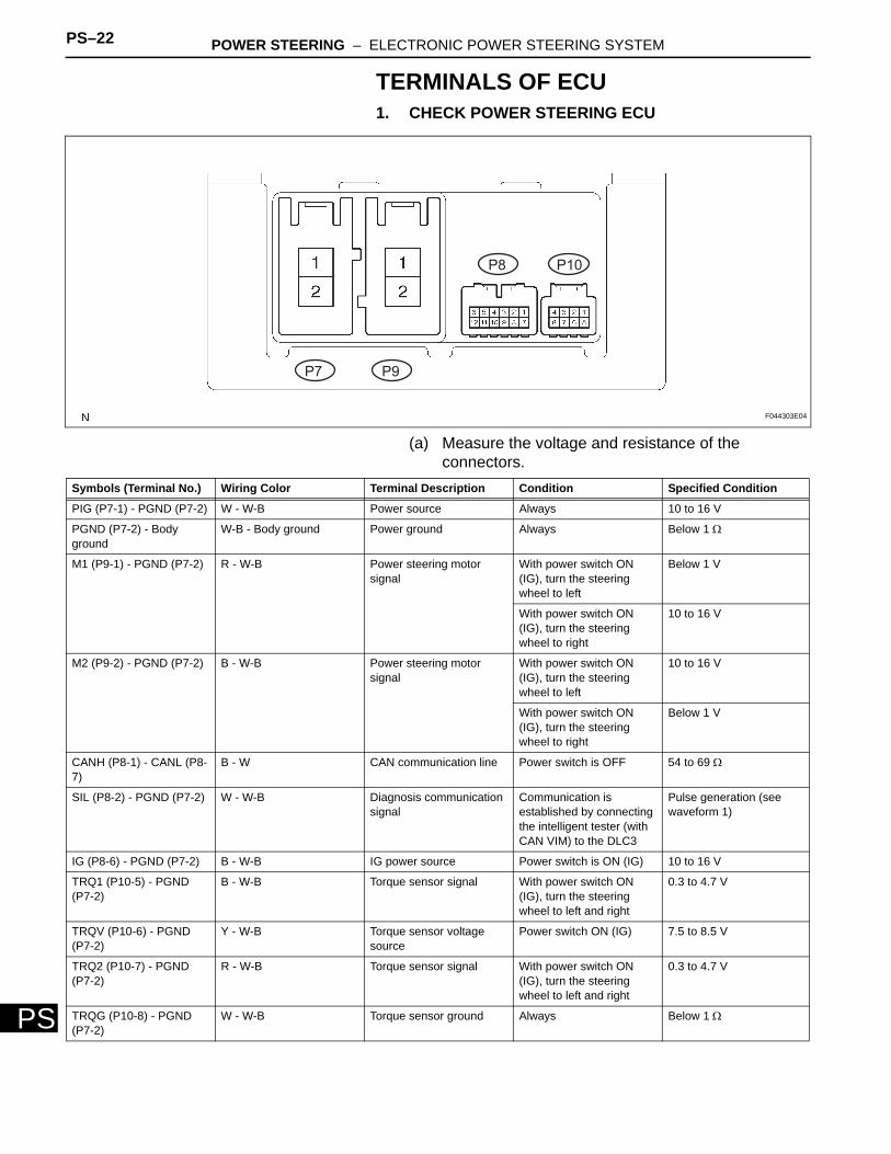
TERMINALS OF ECU1. CHECK POWER STEERING ECU
(a) Measure the voltage and resistance of the connectors.
P7
P8
P9
P10
F044303E04
Symbols (Terminal No.) Wiring Color Terminal Description Condition Specified Condition
PIG (P7-1) - PGND (P7-2) W - W-B Power source Always 10 to 16 V
PGND (P7-2) - Body ground
W-B - Body ground Power ground Always Below 1 Ω
M1 (P9-1) - PGND (P7-2) R - W-B Power steering motor signal
With power switch ON (IG), turn the steering wheel to left
Below 1 V
With power switch ON (IG), turn the steering wheel to right
10 to 16 V
M2 (P9-2) - PGND (P7-2) B - W-B Power steering motor signal
With power switch ON (IG), turn the steering wheel to left
10 to 16 V
With power switch ON (IG), turn the steering wheel to right
Below 1 V
CANH (P8-1) - CANL (P8-7)
B - W CAN communication line Power switch is OFF 54 to 69 Ω
SIL (P8-2) - PGND (P7-2) W - W-B Diagnosis communication signal
Communication is established by connecting the intelligent tester (with CAN VIM) to the DLC3
Pulse generation (see waveform 1)
IG (P8-6) - PGND (P7-2) B - W-B IG power source Power switch is ON (IG) 10 to 16 V
TRQ1 (P10-5) - PGND (P7-2)
B - W-B Torque sensor signal With power switch ON (IG), turn the steering wheel to left and right
0.3 to 4.7 V
TRQV (P10-6) - PGND (P7-2)
Y - W-B Torque sensor voltage source
Power switch ON (IG) 7.5 to 8.5 V
TRQ2 (P10-7) - PGND (P7-2)
R - W-B Torque sensor signal With power switch ON (IG), turn the steering wheel to left and right
0.3 to 4.7 V
TRQG (P10-8) - PGND (P7-2)
W - W-B Torque sensor ground Always Below 1 Ω
POWER STEERING – ELECTRONIC POWER STEERING SYSTEM PS–23
PS
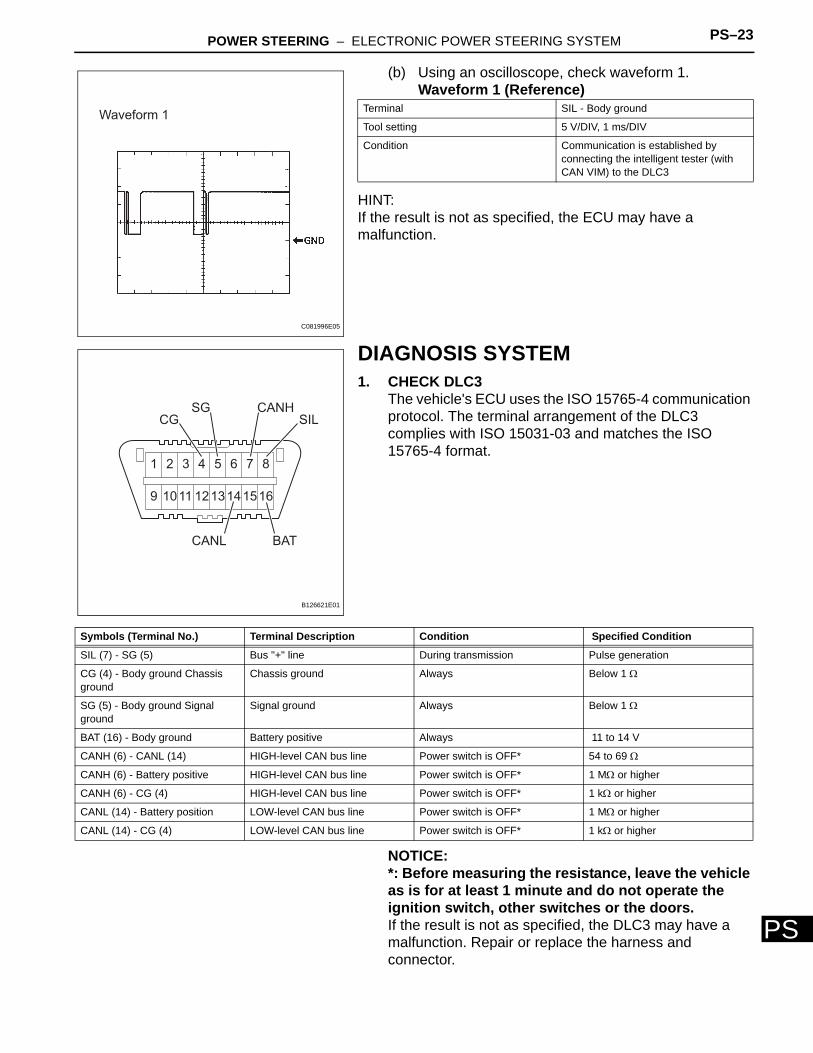
(b) Using an oscilloscope, check waveform 1.Waveform 1 (Reference)
HINT:If the result is not as specified, the ECU may have a malfunction.
DIAGNOSIS SYSTEM1. CHECK DLC3
The vehicle's ECU uses the ISO 15765-4 communication protocol. The terminal arrangement of the DLC3 complies with ISO 15031-03 and matches the ISO 15765-4 format.
NOTICE:*: Before measuring the resistance, leave the vehicle as is for at least 1 minute and do not operate the ignition switch, other switches or the doors.If the result is not as specified, the DLC3 may have a malfunction. Repair or replace the harness and connector.
Waveform 1
C081996E05
Terminal SIL - Body ground
Tool setting 5 V/DIV, 1 ms/DIV
Condition Communication is established by connecting the intelligent tester (with CAN VIM) to the DLC3
1 2 3 4 5 6 7 8
9 1011 1213141516
CGSG CANH
CANL BAT
SIL
B126621E01
Symbols (Terminal No.) Terminal Description Condition Specified Condition
SIL (7) - SG (5) Bus "+" line During transmission Pulse generation
CG (4) - Body ground Chassis ground
Chassis ground Always Below 1 Ω
SG (5) - Body ground Signal ground
Signal ground Always Below 1 Ω
BAT (16) - Body ground Battery positive Always 11 to 14 V
CANH (6) - CANL (14) HIGH-level CAN bus line Power switch is OFF* 54 to 69 Ω
CANH (6) - Battery positive HIGH-level CAN bus line Power switch is OFF* 1 MΩ or higher
CANH (6) - CG (4) HIGH-level CAN bus line Power switch is OFF* 1 kΩ or higher
CANL (14) - Battery position LOW-level CAN bus line Power switch is OFF* 1 MΩ or higher
CANL (14) - CG (4) LOW-level CAN bus line Power switch is OFF* 1 kΩ or higher
PS–24 POWER STEERING – ELECTRONIC POWER STEERING SYSTEM
PS
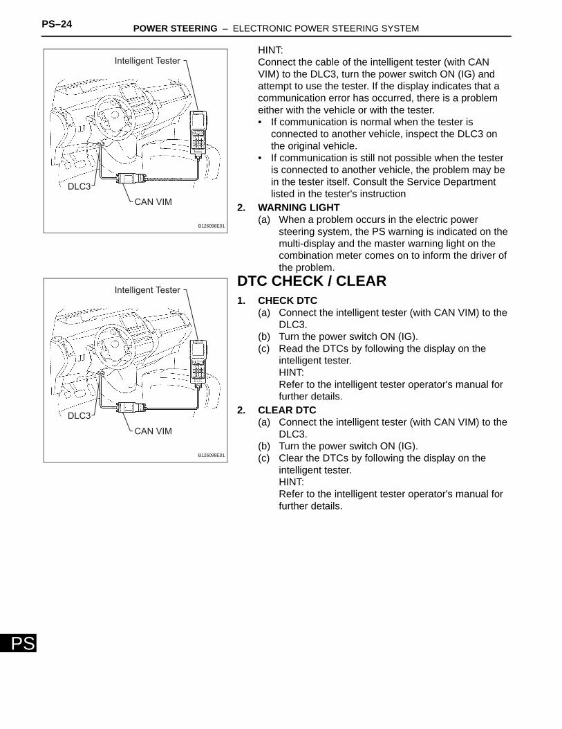
HINT:Connect the cable of the intelligent tester (with CAN VIM) to the DLC3, turn the power switch ON (IG) and attempt to use the tester. If the display indicates that a communication error has occurred, there is a problem either with the vehicle or with the tester.• If communication is normal when the tester is
connected to another vehicle, inspect the DLC3 on the original vehicle.
• If communication is still not possible when the tester is connected to another vehicle, the problem may be in the tester itself. Consult the Service Department listed in the tester's instruction
2. WARNING LIGHT(a) When a problem occurs in the electric power
steering system, the PS warning is indicated on the multi-display and the master warning light on the combination meter comes on to inform the driver of the problem.
DTC CHECK / CLEAR1. CHECK DTC
(a) Connect the intelligent tester (with CAN VIM) to the DLC3.
(b) Turn the power switch ON (IG).(c) Read the DTCs by following the display on the
intelligent tester.HINT:Refer to the intelligent tester operator's manual for further details.
2. CLEAR DTC(a) Connect the intelligent tester (with CAN VIM) to the
DLC3.(b) Turn the power switch ON (IG).(c) Clear the DTCs by following the display on the
intelligent tester.HINT:Refer to the intelligent tester operator's manual for further details.
DLC3
CAN VIM
Intelligent Tester
B126098E01
DLC3
CAN VIM
Intelligent Tester
B126098E01
POWER STEERING – ELECTRONIC POWER STEERING SYSTEM PS–25
PS
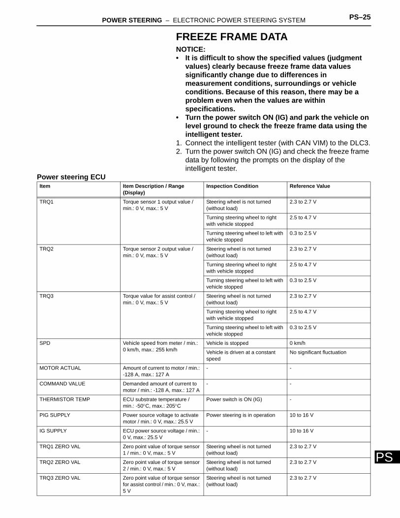
FREEZE FRAME DATANOTICE:• It is difficult to show the specified values (judgment
values) clearly because freeze frame data values significantly change due to differences in measurement conditions, surroundings or vehicle conditions. Because of this reason, there may be a problem even when the values are within specifications.
• Turn the power switch ON (IG) and park the vehicle on level ground to check the freeze frame data using the intelligent tester.
1. Connect the intelligent tester (with CAN VIM) to the DLC3.2. Turn the power switch ON (IG) and check the freeze frame
data by following the prompts on the display of the intelligent tester.
Power steering ECUItem Item Description / Range
(Display)Inspection Condition Reference Value
TRQ1 Torque sensor 1 output value / min.: 0 V, max.: 5 V
Steering wheel is not turned (without load)
2.3 to 2.7 V
Turning steering wheel to right with vehicle stopped
2.5 to 4.7 V
Turning steering wheel to left with vehicle stopped
0.3 to 2.5 V
TRQ2 Torque sensor 2 output value / min.: 0 V, max.: 5 V
Steering wheel is not turned (without load)
2.3 to 2.7 V
Turning steering wheel to right with vehicle stopped
2.5 to 4.7 V
Turning steering wheel to left with vehicle stopped
0.3 to 2.5 V
TRQ3 Torque value for assist control / min.: 0 V, max.: 5 V
Steering wheel is not turned (without load)
2.3 to 2.7 V
Turning steering wheel to right with vehicle stopped
2.5 to 4.7 V
Turning steering wheel to left with vehicle stopped
0.3 to 2.5 V
SPD Vehicle speed from meter / min.: 0 km/h, max.: 255 km/h
Vehicle is stopped 0 km/h
Vehicle is driven at a constant speed
No significant fluctuation
MOTOR ACTUAL Amount of current to motor / min.: -128 A, max.: 127 A
- -
COMMAND VALUE Demanded amount of current to motor / min.: -128 A, max.: 127 A
- -
THERMISTOR TEMP ECU substrate temperature / min.: -50°C, max.: 205°C
Power switch is ON (IG) -
PIG SUPPLY Power source voltage to activate motor / min.: 0 V, max.: 25.5 V
Power steering is in operation 10 to 16 V
IG SUPPLY ECU power source voltage / min.: 0 V, max.: 25.5 V
- 10 to 16 V
TRQ1 ZERO VAL Zero point value of torque sensor 1 / min.: 0 V, max.: 5 V
Steering wheel is not turned (without load)
2.3 to 2.7 V
TRQ2 ZERO VAL Zero point value of torque sensor 2 / min.: 0 V, max.: 5 V
Steering wheel is not turned (without load)
2.3 to 2.7 V
TRQ3 ZERO VAL Zero point value of torque sensor for assist control / min.: 0 V, max.: 5 V
Steering wheel is not turned (without load)
2.3 to 2.7 V
PS–26 POWER STEERING – ELECTRONIC POWER STEERING SYSTEM
PS
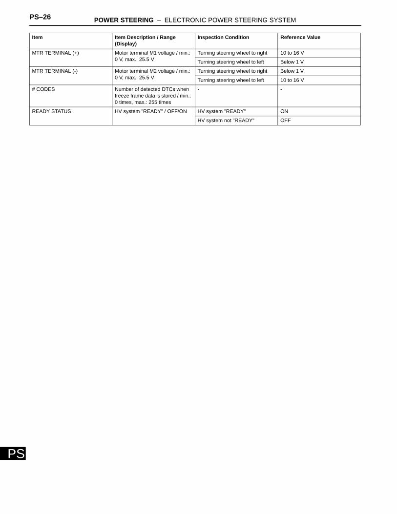
MTR TERMINAL (+) Motor terminal M1 voltage / min.: 0 V, max.: 25.5 V
Turning steering wheel to right 10 to 16 V
Turning steering wheel to left Below 1 V
MTR TERMINAL (-) Motor terminal M2 voltage / min.: 0 V, max.: 25.5 V
Turning steering wheel to right Below 1 V
Turning steering wheel to left 10 to 16 V
# CODES Number of detected DTCs when freeze frame data is stored / min.: 0 times, max.: 255 times
- -
READY STATUS HV system "READY" / OFF/ON HV system "READY" ON
HV system not "READY" OFF
Item Item Description / Range (Display)
Inspection Condition Reference Value
POWER STEERING – ELECTRONIC POWER STEERING SYSTEM PS–27
PS
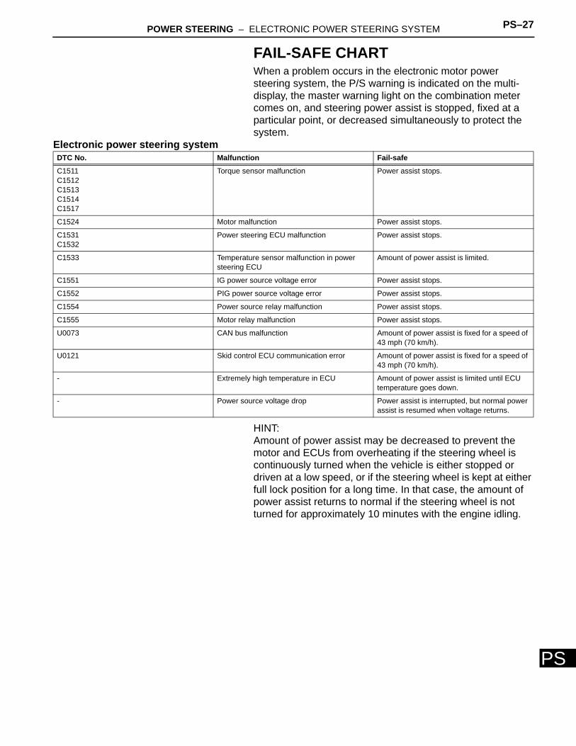
FAIL-SAFE CHARTWhen a problem occurs in the electronic motor power steering system, the P/S warning is indicated on the multi-display, the master warning light on the combination meter comes on, and steering power assist is stopped, fixed at a particular point, or decreased simultaneously to protect the system.
Electronic power steering system
HINT:Amount of power assist may be decreased to prevent the motor and ECUs from overheating if the steering wheel is continuously turned when the vehicle is either stopped or driven at a low speed, or if the steering wheel is kept at either full lock position for a long time. In that case, the amount of power assist returns to normal if the steering wheel is not turned for approximately 10 minutes with the engine idling.
DTC No. Malfunction Fail-safe
C1511C1512C1513C1514C1517
Torque sensor malfunction Power assist stops.
C1524 Motor malfunction Power assist stops.
C1531C1532
Power steering ECU malfunction Power assist stops.
C1533 Temperature sensor malfunction in power steering ECU
Amount of power assist is limited.
C1551 IG power source voltage error Power assist stops.
C1552 PIG power source voltage error Power assist stops.
C1554 Power source relay malfunction Power assist stops.
C1555 Motor relay malfunction Power assist stops.
U0073 CAN bus malfunction Amount of power assist is fixed for a speed of 43 mph (70 km/h).
U0121 Skid control ECU communication error Amount of power assist is fixed for a speed of 43 mph (70 km/h).
- Extremely high temperature in ECU Amount of power assist is limited until ECU temperature goes down.
- Power source voltage drop Power assist is interrupted, but normal power assist is resumed when voltage returns.
PS–28 POWER STEERING – ELECTRONIC POWER STEERING SYSTEM
PS
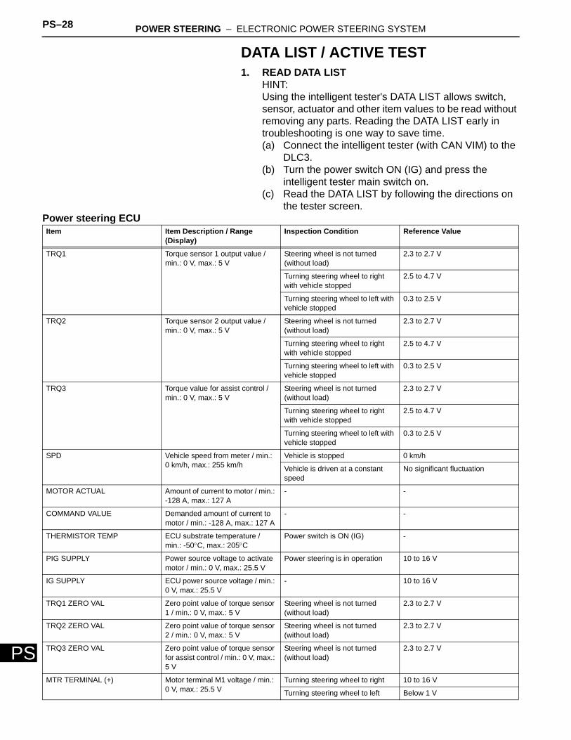
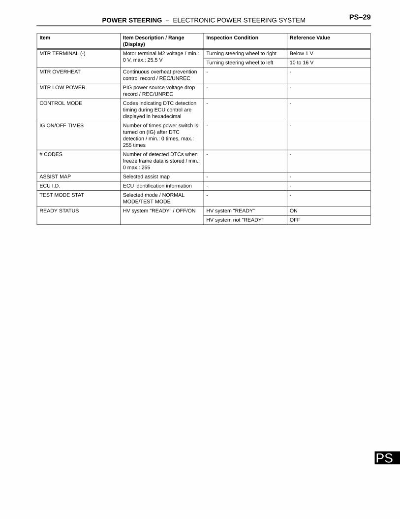
DATA LIST / ACTIVE TEST1. READ DATA LIST
HINT:Using the intelligent tester's DATA LIST allows switch, sensor, actuator and other item values to be read without removing any parts. Reading the DATA LIST early in troubleshooting is one way to save time.(a) Connect the intelligent tester (with CAN VIM) to the
DLC3.(b) Turn the power switch ON (IG) and press the
intelligent tester main switch on.(c) Read the DATA LIST by following the directions on
the tester screen.Power steering ECUItem Item Description / Range
(Display)Inspection Condition Reference Value
TRQ1 Torque sensor 1 output value / min.: 0 V, max.: 5 V
Steering wheel is not turned (without load)
2.3 to 2.7 V
Turning steering wheel to right with vehicle stopped
2.5 to 4.7 V
Turning steering wheel to left with vehicle stopped
0.3 to 2.5 V
TRQ2 Torque sensor 2 output value / min.: 0 V, max.: 5 V
Steering wheel is not turned (without load)
2.3 to 2.7 V
Turning steering wheel to right with vehicle stopped
2.5 to 4.7 V
Turning steering wheel to left with vehicle stopped
0.3 to 2.5 V
TRQ3 Torque value for assist control / min.: 0 V, max.: 5 V
Steering wheel is not turned (without load)
2.3 to 2.7 V
Turning steering wheel to right with vehicle stopped
2.5 to 4.7 V
Turning steering wheel to left with vehicle stopped
0.3 to 2.5 V
SPD Vehicle speed from meter / min.: 0 km/h, max.: 255 km/h
Vehicle is stopped 0 km/h
Vehicle is driven at a constant speed
No significant fluctuation
MOTOR ACTUAL Amount of current to motor / min.: -128 A, max.: 127 A
- -
COMMAND VALUE Demanded amount of current to motor / min.: -128 A, max.: 127 A
- -
THERMISTOR TEMP ECU substrate temperature / min.: -50°C, max.: 205°C
Power switch is ON (IG) -
PIG SUPPLY Power source voltage to activate motor / min.: 0 V, max.: 25.5 V
Power steering is in operation 10 to 16 V
IG SUPPLY ECU power source voltage / min.: 0 V, max.: 25.5 V
- 10 to 16 V
TRQ1 ZERO VAL Zero point value of torque sensor 1 / min.: 0 V, max.: 5 V
Steering wheel is not turned (without load)
2.3 to 2.7 V
TRQ2 ZERO VAL Zero point value of torque sensor 2 / min.: 0 V, max.: 5 V
Steering wheel is not turned (without load)
2.3 to 2.7 V
TRQ3 ZERO VAL Zero point value of torque sensor for assist control / min.: 0 V, max.: 5 V
Steering wheel is not turned (without load)
2.3 to 2.7 V
MTR TERMINAL (+) Motor terminal M1 voltage / min.: 0 V, max.: 25.5 V
Turning steering wheel to right 10 to 16 V
Turning steering wheel to left Below 1 V
POWER STEERING – ELECTRONIC POWER STEERING SYSTEM PS–29
PS
MTR TERMINAL (-) Motor terminal M2 voltage / min.: 0 V, max.: 25.5 V
Turning steering wheel to right Below 1 V
Turning steering wheel to left 10 to 16 V
MTR OVERHEAT Continuous overheat prevention control record / REC/UNREC
- -
MTR LOW POWER PIG power source voltage drop record / REC/UNREC
- -
CONTROL MODE Codes indicating DTC detection timing during ECU control are displayed in hexadecimal
- -
IG ON/OFF TIMES Number of times power switch is turned on (IG) after DTC detection / min.: 0 times, max.: 255 times
- -
# CODES Number of detected DTCs when freeze frame data is stored / min.: 0 max.: 255
- -
ASSIST MAP Selected assist map - -
ECU I.D. ECU identification information - -
TEST MODE STAT Selected mode / NORMAL MODE/TEST MODE
- -
READY STATUS HV system "READY" / OFF/ON HV system "READY" ON
HV system not "READY" OFF
Item Item Description / Range (Display)
Inspection Condition Reference Value
PS–30 POWER STEERING – ELECTRONIC POWER STEERING SYSTEM
PS
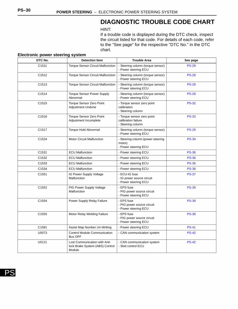
DIAGNOSTIC TROUBLE CODE CHARTHINT:If a trouble code is displayed during the DTC check, inspect the circuit listed for that code. For details of each code, refer to the "See page" for the respective "DTC No." in the DTC chart.
Electronic power steering systemDTC No. Detection Item Trouble Area See page
C1511 Torque Sensor Circuit Malfunction - Steering column (torque sensor)- Power steering ECU
PS-29
C1512 Torque Sensor Circuit Malfunction - Steering column (torque sensor)- Power steering ECU
PS-29
C1513 Torque Sensor Circuit Malfunction - Steering column (torque sensor)- Power steering ECU
PS-29
C1514 Torque Sensor Power Supply Abnormal
- Steering column (torque sensor)- Power steering ECU
PS-29
C1515 Torque Sensor Zero Point Adjustment Undone
- Torque sensor zero point calibration- Steering column
PS-32
C1516 Torque Sensor Zero Point Adjustment Incomplete
- Torque sensor zero point calibration failure- Steering column
PS-33
C1517 Torque Hold Abnormal - Steering column (torque sensor)- Power steering ECU
PS-29
C1524 Motor Circuit Malfunction - Steering column (power steering motor)- Power steering ECU
PS-34
C1531 ECU Malfunction - Power steering ECU PS-36
C1532 ECU Malfunction - Power steering ECU PS-36
C1533 ECU Malfunction - Power steering ECU PS-36
C1534 ECU Malfunction - Power steering ECU PS-36
C1551 IG Power Supply Voltage Malfunction
- ECU-IG fuse- IG power source circuit- Power steering ECU
PS-37
C1552 PIG Power Supply Voltage Malfunction
- EPS fuse- PIG power source circuit- Power steering ECU
PS-39
C1554 Power Supply Relay Failure - EPS fuse- PIG power source circuit- Power steering ECU
PS-39
C1555 Motor Relay Welding Failure - EPS fuse- PIG power source circuit- Power steering ECU
PS-39
C1581 Assist Map Number Un-Writing - Power steering ECU PS-41
U0073 Control Module Communication Bus OFF
- CAN communication system PS-42
U0121 Lost Communication with Anti-lock Brake System (ABS) Control Module
- CAN communication system- Skid control ECU
PS-42
POWER STEERING – ELECTRONIC POWER STEERING SYSTEM PS–31
PS
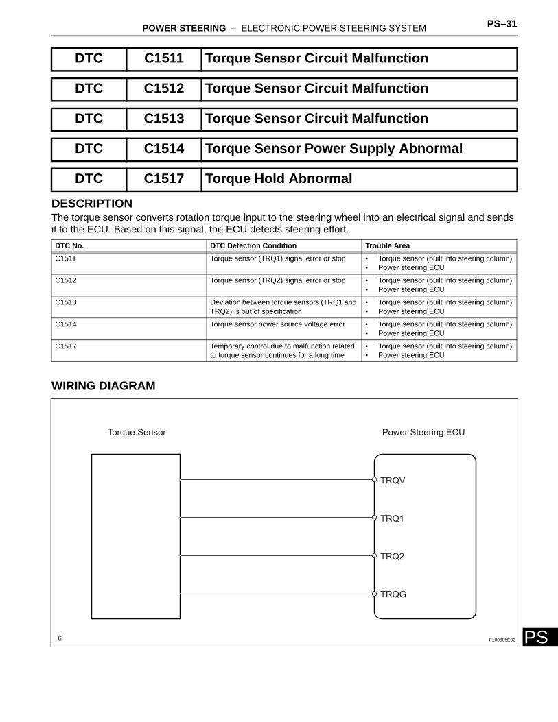
DESCRIPTIONThe torque sensor converts rotation torque input to the steering wheel into an electrical signal and sends it to the ECU. Based on this signal, the ECU detects steering effort.
WIRING DIAGRAM
DTC C1511 Torque Sensor Circuit Malfunction
DTC C1512 Torque Sensor Circuit Malfunction
DTC C1513 Torque Sensor Circuit Malfunction
DTC C1514 Torque Sensor Power Supply Abnormal
DTC C1517 Torque Hold Abnormal
DTC No. DTC Detection Condition Trouble Area
C1511 Torque sensor (TRQ1) signal error or stop • Torque sensor (built into steering column)• Power steering ECU
C1512 Torque sensor (TRQ2) signal error or stop • Torque sensor (built into steering column)• Power steering ECU
C1513 Deviation between torque sensors (TRQ1 and TRQ2) is out of specification
• Torque sensor (built into steering column)• Power steering ECU
C1514 Torque sensor power source voltage error • Torque sensor (built into steering column)• Power steering ECU
C1517 Temporary control due to malfunction related to torque sensor continues for a long time
• Torque sensor (built into steering column)• Power steering ECU
Torque Sensor Power Steering ECU
TRQV
TRQ1
TRQ2
TRQG
F100805E02
PS–32 POWER STEERING – ELECTRONIC POWER STEERING SYSTEM
PS
INSPECTION PROCEDURE
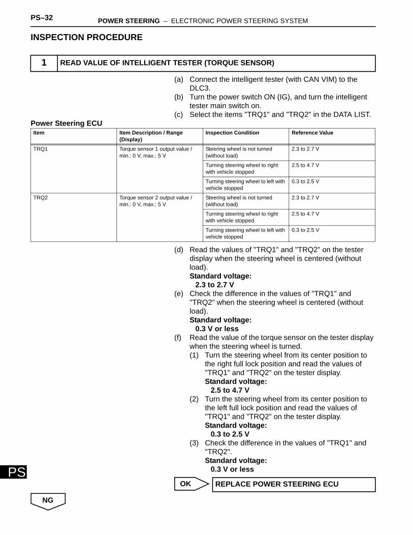
(a) Connect the intelligent tester (with CAN VIM) to the DLC3.
(b) Turn the power switch ON (IG), and turn the intelligent tester main switch on.
(c) Select the items "TRQ1" and "TRQ2" in the DATA LIST.Power Steering ECU
(d) Read the values of "TRQ1" and "TRQ2" on the tester display when the steering wheel is centered (without load).Standard voltage:
2.3 to 2.7 V(e) Check the difference in the values of "TRQ1" and
"TRQ2" when the steering wheel is centered (without load).Standard voltage:
0.3 V or less(f) Read the value of the torque sensor on the tester display
when the steering wheel is turned.(1) Turn the steering wheel from its center position to
the right full lock position and read the values of "TRQ1" and "TRQ2" on the tester display.Standard voltage:
2.5 to 4.7 V(2) Turn the steering wheel from its center position to
the left full lock position and read the values of "TRQ1" and "TRQ2" on the tester display.Standard voltage:
0.3 to 2.5 V(3) Check the difference in the values of "TRQ1" and
"TRQ2".Standard voltage:
0.3 V or less
OK
NG
1 READ VALUE OF INTELLIGENT TESTER (TORQUE SENSOR)
Item Item Description / Range (Display)
Inspection Condition Reference Value
TRQ1 Torque sensor 1 output value / min.: 0 V, max.: 5 V
Steering wheel is not turned (without load)
2.3 to 2.7 V
Turning steering wheel to right with vehicle stopped
2.5 to 4.7 V
Turning steering wheel to left with vehicle stopped
0.3 to 2.5 V
TRQ2 Torque sensor 2 output value / min.: 0 V, max.: 5 V
Steering wheel is not turned (without load)
2.3 to 2.7 V
Turning steering wheel to right with vehicle stopped
2.5 to 4.7 V
Turning steering wheel to left with vehicle stopped
0.3 to 2.5 V
REPLACE POWER STEERING ECU
POWER STEERING – ELECTRONIC POWER STEERING SYSTEM PS–33
PS
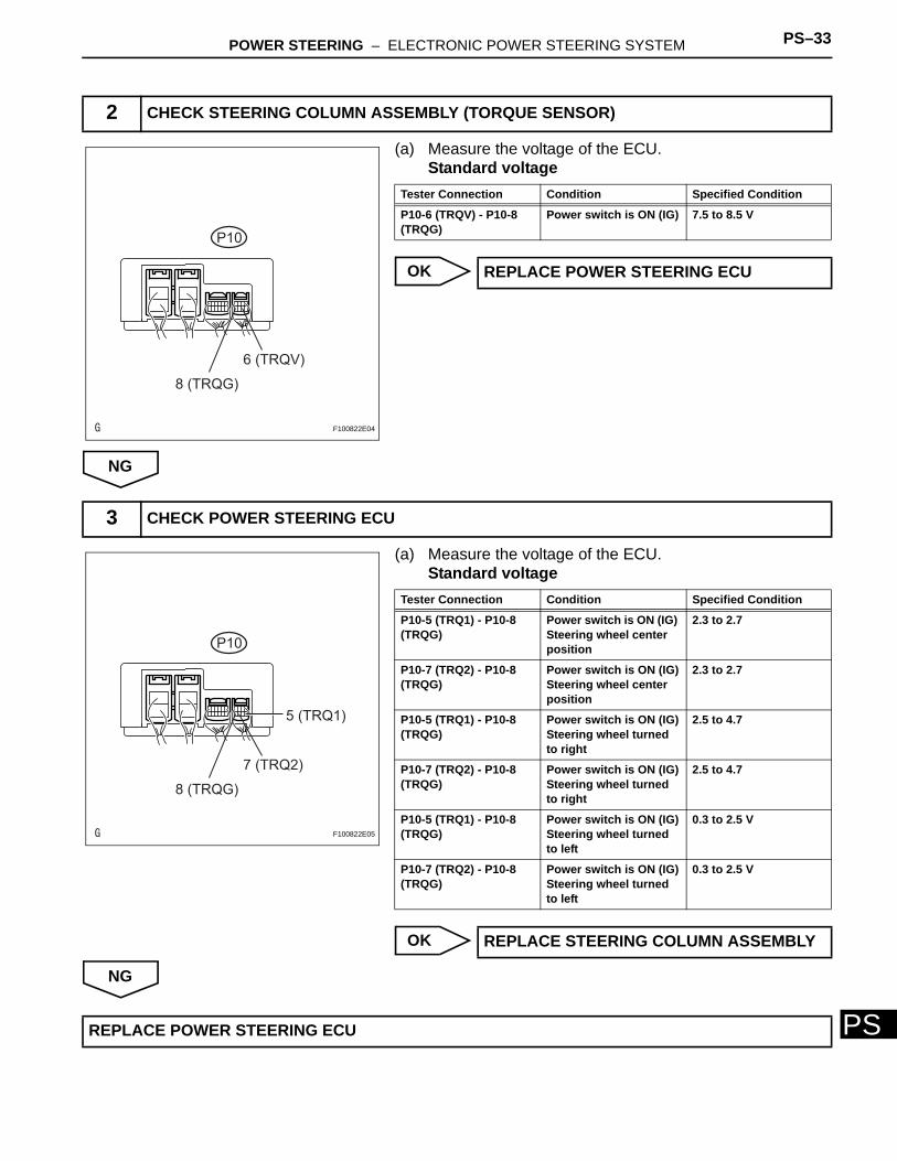
(a) Measure the voltage of the ECU.Standard voltage
OK
NG
(a) Measure the voltage of the ECU.Standard voltage
OK
NG
2 CHECK STEERING COLUMN ASSEMBLY (TORQUE SENSOR)
P10
6 (TRQV)
8 (TRQG)
F100822E04
Tester Connection Condition Specified Condition
P10-6 (TRQV) - P10-8 (TRQG)
Power switch is ON (IG) 7.5 to 8.5 V
REPLACE POWER STEERING ECU
3 CHECK POWER STEERING ECU
P10
7 (TRQ2)
5 (TRQ1)
8 (TRQG)
F100822E05
Tester Connection Condition Specified Condition
P10-5 (TRQ1) - P10-8 (TRQG)
Power switch is ON (IG) Steering wheel center position
2.3 to 2.7
P10-7 (TRQ2) - P10-8 (TRQG)
Power switch is ON (IG)Steering wheel center position
2.3 to 2.7
P10-5 (TRQ1) - P10-8 (TRQG)
Power switch is ON (IG)Steering wheel turned to right
2.5 to 4.7
P10-7 (TRQ2) - P10-8 (TRQG)
Power switch is ON (IG)Steering wheel turned to right
2.5 to 4.7
P10-5 (TRQ1) - P10-8 (TRQG)
Power switch is ON (IG)Steering wheel turned to left
0.3 to 2.5 V
P10-7 (TRQ2) - P10-8 (TRQG)
Power switch is ON (IG)Steering wheel turned to left
0.3 to 2.5 V
REPLACE STEERING COLUMN ASSEMBLY
REPLACE POWER STEERING ECU
PS–34 POWER STEERING – ELECTRONIC POWER STEERING SYSTEM
PS
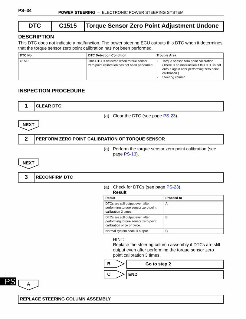
DESCRIPTIONThis DTC does not indicate a malfunction. The power steering ECU outputs this DTC when it determines that the torque sensor zero point calibration has not been performed.
INSPECTION PROCEDURE
(a) Clear the DTC (see page PS-23).
NEXT
(a) Perform the torque sensor zero point calibration (see page PS-13).
NEXT
(a) Check for DTCs (see page PS-23).Result
HINT:Replace the steering column assembly if DTCs are still output even after performing the torque sensor zero point calibration 3 times.
B
C
A
DTC C1515 Torque Sensor Zero Point Adjustment Undone
DTC No. DTC Detection Condition Trouble Area
C1515 This DTC is detected when torque sensor zero point calibration has not been performed.
• Torque sensor zero point calibration(There is no malfunction if this DTC is not output again after performing zero point calibration.)
• Steering column
1 CLEAR DTC
2 PERFORM ZERO POINT CALIBRATION OF TORQUE SENSOR
3 RECONFIRM DTC
Result Proceed to
DTCs are still output even after performing torque sensor zero point calibration 3 times.
A
DTCs are still output even after performing torque sensor zero point calibration once or twice.
B
Normal system code is output. C
Go to step 2
END
REPLACE STEERING COLUMN ASSEMBLY
POWER STEERING – ELECTRONIC POWER STEERING SYSTEM PS–35
PS
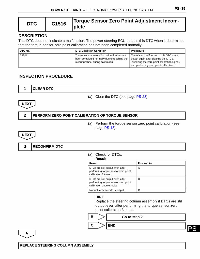
DESCRIPTIONThis DTC does not indicate a malfunction. The power steering ECU outputs this DTC when it determines that the torque sensor zero point calibration has not been completed normally.
INSPECTION PROCEDURE
(a) Clear the DTC (see page PS-23).
NEXT
(a) Perform the torque sensor zero point calibration (see page PS-13).
NEXT
(a) Check for DTCs.Result
HINT:Replace the steering column assembly if DTCs are still output even after performing the torque sensor zero point calibration 3 times.
B
C
A
DTC C1516 Torque Sensor Zero Point Adjustment Incom-plete
DTC No. DTC Detection Condition Procedure
C1516 Torque sensor zero point calibration has not been completed normally due to touching the steering wheel during calibration.
There is no malfunction if this DTC is not output again after clearing the DTCs, initializing the zero point calibration signal, and performing zero point calibration.
1 CLEAR DTC
2 PERFORM ZERO POINT CALIBRATION OF TORQUE SENSOR
3 RECONFIRM DTC
Result Proceed to
DTCs are still output even after performing torque sensor zero point calibration 3 times.
A
DTCs are still output even after performing torque sensor zero point calibration once or twice.
B
Normal system code is output. C
Go to step 2
END
REPLACE STEERING COLUMN ASSEMBLY
PS–36 POWER STEERING – ELECTRONIC POWER STEERING SYSTEM
PS
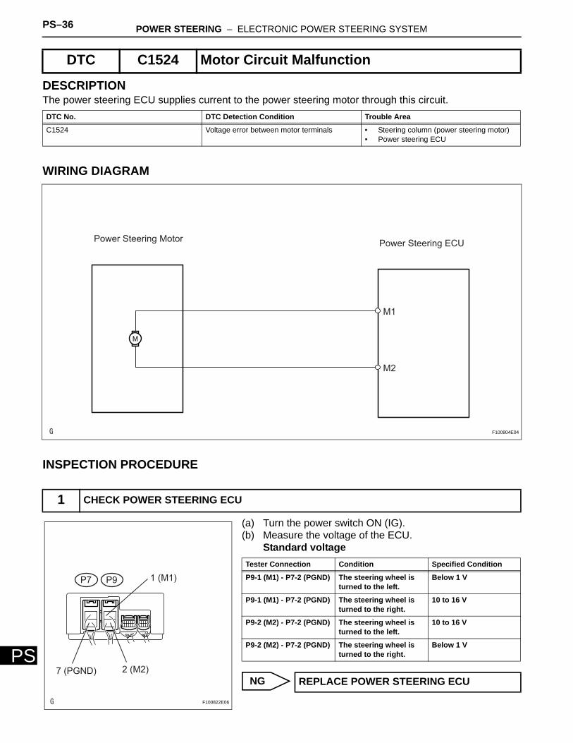
DESCRIPTIONThe power steering ECU supplies current to the power steering motor through this circuit.
WIRING DIAGRAM
INSPECTION PROCEDURE
(a) Turn the power switch ON (IG).(b) Measure the voltage of the ECU.
Standard voltage
NG
DTC C1524 Motor Circuit Malfunction
DTC No. DTC Detection Condition Trouble Area
C1524 Voltage error between motor terminals • Steering column (power steering motor)• Power steering ECU
1 CHECK POWER STEERING ECU
Power Steering MotorPower Steering ECU
M1
M2
F100804E04
P7 P9 1 (M1)
2 (M2)7 (PGND)
F100822E06
Tester Connection Condition Specified Condition
P9-1 (M1) - P7-2 (PGND) The steering wheel is turned to the left.
Below 1 V
P9-1 (M1) - P7-2 (PGND) The steering wheel is turned to the right.
10 to 16 V
P9-2 (M2) - P7-2 (PGND) The steering wheel is turned to the left.
10 to 16 V
P9-2 (M2) - P7-2 (PGND) The steering wheel is turned to the right.
Below 1 V
REPLACE POWER STEERING ECU
POWER STEERING – ELECTRONIC POWER STEERING SYSTEM PS–37
PS
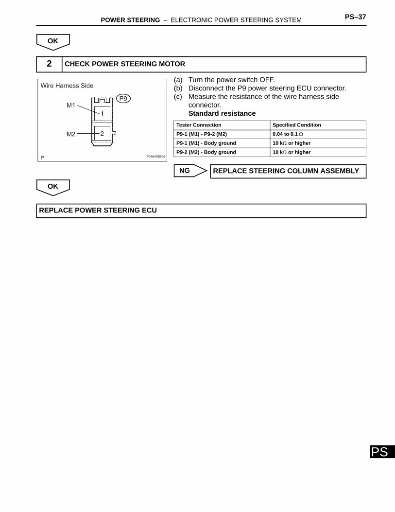
OK
(a) Turn the power switch OFF.(b) Disconnect the P9 power steering ECU connector.(c) Measure the resistance of the wire harness side
connector.Standard resistance
NG
OK
2 CHECK POWER STEERING MOTOR
M1
M2
P9
Wire Harness Side
F046435E06
Tester Connection Specified Condition
P9-1 (M1) - P9-2 (M2) 0.04 to 0.1 Ω
P9-1 (M1) - Body ground 10 kΩ or higher
P9-2 (M2) - Body ground 10 kΩ or higher
REPLACE STEERING COLUMN ASSEMBLY
REPLACE POWER STEERING ECU
PS–38 POWER STEERING – ELECTRONIC POWER STEERING SYSTEM
PS
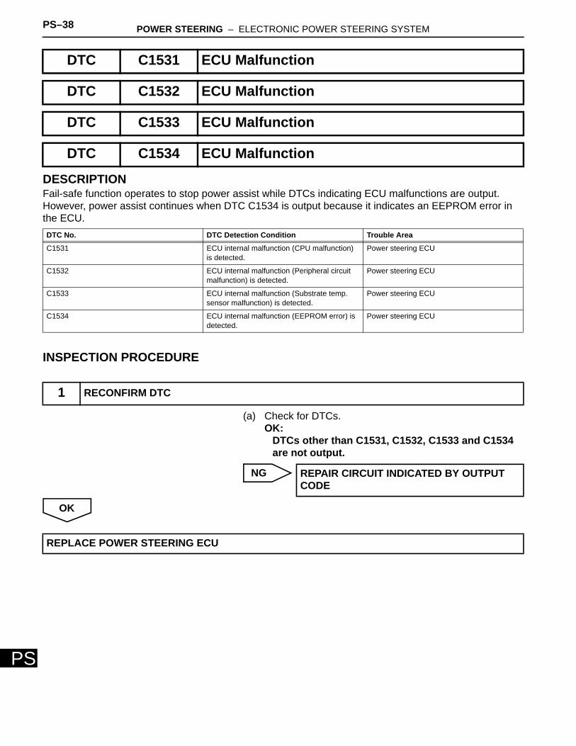
DESCRIPTIONFail-safe function operates to stop power assist while DTCs indicating ECU malfunctions are output. However, power assist continues when DTC C1534 is output because it indicates an EEPROM error in the ECU.
INSPECTION PROCEDURE
(a) Check for DTCs.OK:
DTCs other than C1531, C1532, C1533 and C1534 are not output.
NG
OK
DTC C1531 ECU Malfunction
DTC C1532 ECU Malfunction
DTC C1533 ECU Malfunction
DTC C1534 ECU Malfunction
DTC No. DTC Detection Condition Trouble Area
C1531 ECU internal malfunction (CPU malfunction) is detected.
Power steering ECU
C1532 ECU internal malfunction (Peripheral circuit malfunction) is detected.
Power steering ECU
C1533 ECU internal malfunction (Substrate temp. sensor malfunction) is detected.
Power steering ECU
C1534 ECU internal malfunction (EEPROM error) is detected.
Power steering ECU
1 RECONFIRM DTC
REPAIR CIRCUIT INDICATED BY OUTPUT CODE
REPLACE POWER STEERING ECU
POWER STEERING – ELECTRONIC POWER STEERING SYSTEM PS–39
PS
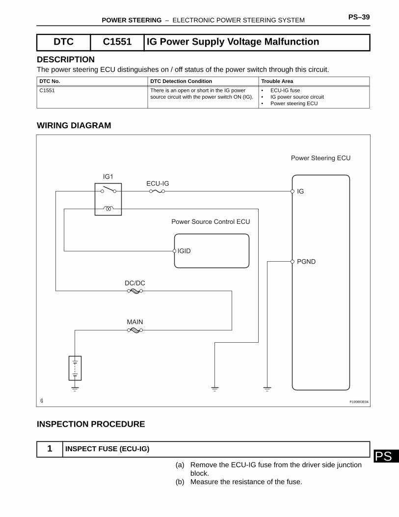
DESCRIPTIONThe power steering ECU distinguishes on / off status of the power switch through this circuit.
WIRING DIAGRAM
INSPECTION PROCEDURE
(a) Remove the ECU-IG fuse from the driver side junction block.
(b) Measure the resistance of the fuse.
DTC C1551 IG Power Supply Voltage Malfunction
DTC No. DTC Detection Condition Trouble Area
C1551 There is an open or short in the IG power source circuit with the power switch ON (IG).
• ECU-IG fuse• IG power source circuit• Power steering ECU
1 INSPECT FUSE (ECU-IG)
Power Steering ECU
IG
PGND
Power Source Control ECU
IG1ECU-IG
DC/DC
MAIN
IGID
F100803E04
PS–40 POWER STEERING – ELECTRONIC POWER STEERING SYSTEM
PS
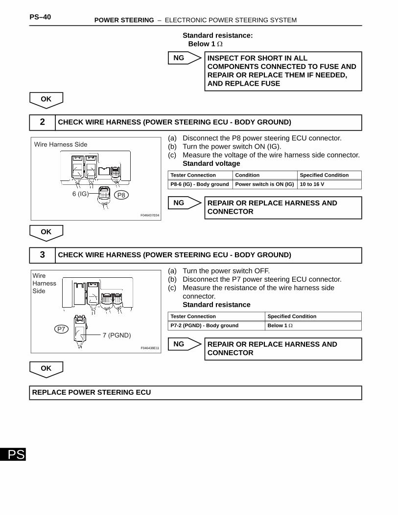
Standard resistance:Below 1 Ω
NG
OK
(a) Disconnect the P8 power steering ECU connector.(b) Turn the power switch ON (IG).(c) Measure the voltage of the wire harness side connector.
Standard voltage
NG
OK
(a) Turn the power switch OFF.(b) Disconnect the P7 power steering ECU connector.(c) Measure the resistance of the wire harness side
connector.Standard resistance
NG
OK
INSPECT FOR SHORT IN ALL COMPONENTS CONNECTED TO FUSE AND REPAIR OR REPLACE THEM IF NEEDED, AND REPLACE FUSE
2 CHECK WIRE HARNESS (POWER STEERING ECU - BODY GROUND)
6 (IG) P8
Wire Harness Side
F046437E04
Tester Connection Condition Specified Condition
P8-6 (IG) - Body ground Power switch is ON (IG) 10 to 16 V
REPAIR OR REPLACE HARNESS AND CONNECTOR
3 CHECK WIRE HARNESS (POWER STEERING ECU - BODY GROUND)
7 (PGND)P7
Wire
Harness
Side
F046438E11
Tester Connection Specified Condition
P7-2 (PGND) - Body ground Below 1 Ω
REPAIR OR REPLACE HARNESS AND CONNECTOR
REPLACE POWER STEERING ECU
POWER STEERING – ELECTRONIC POWER STEERING SYSTEM PS–41
PS
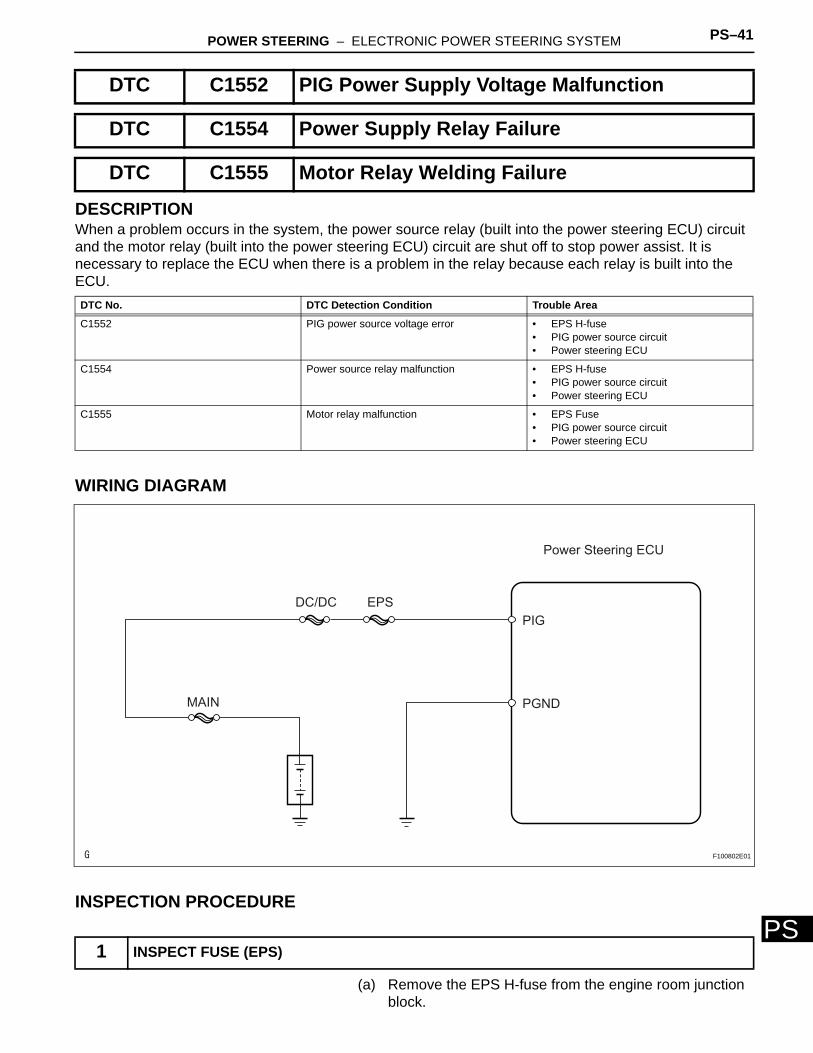
DESCRIPTIONWhen a problem occurs in the system, the power source relay (built into the power steering ECU) circuit and the motor relay (built into the power steering ECU) circuit are shut off to stop power assist. It is necessary to replace the ECU when there is a problem in the relay because each relay is built into the ECU.
WIRING DIAGRAM
INSPECTION PROCEDURE
(a) Remove the EPS H-fuse from the engine room junction block.
DTC C1552 PIG Power Supply Voltage Malfunction
DTC C1554 Power Supply Relay Failure
DTC C1555 Motor Relay Welding Failure
DTC No. DTC Detection Condition Trouble Area
C1552 PIG power source voltage error • EPS H-fuse• PIG power source circuit• Power steering ECU
C1554 Power source relay malfunction • EPS H-fuse• PIG power source circuit• Power steering ECU
C1555 Motor relay malfunction • EPS Fuse• PIG power source circuit• Power steering ECU
1 INSPECT FUSE (EPS)
Power Steering ECU
PIG
PGNDMAIN
EPSDC/DC
F100802E01
PS–42 POWER STEERING – ELECTRONIC POWER STEERING SYSTEM
PS
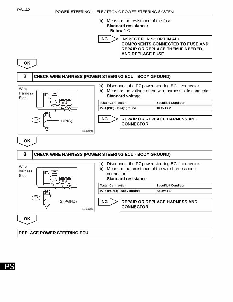
(b) Measure the resistance of the fuse.Standard resistance:
Below 1 Ω
NG
OK
(a) Disconnect the P7 power steering ECU connector.(b) Measure the voltage of the wire harness side connector.
Standard voltage
NG
OK
(a) Disconnect the P7 power steering ECU connector.(b) Measure the resistance of the wire harness side
connector.Standard resistance
NG
OK
INSPECT FOR SHORT IN ALL COMPONENTS CONNECTED TO FUSE AND REPAIR OR REPLACE THEM IF NEEDED, AND REPLACE FUSE
2 CHECK WIRE HARNESS (POWER STEERING ECU - BODY GROUND)
1 (PIG)P7
Wire
Harness
Side
F046438E12
Tester Connection Specified Condition
P7-1 (PIG) - Body ground 10 to 16 V
REPAIR OR REPLACE HARNESS AND CONNECTOR
3 CHECK WIRE HARNESS (POWER STEERING ECU - BODY GROUND)
2 (PGND)P7
Wire
harness
Side
F046438E06
Tester Connection Specified Condition
P7-2 (PGND) - Body ground Below 1 Ω
REPAIR OR REPLACE HARNESS AND CONNECTOR
REPLACE POWER STEERING ECU
POWER STEERING – ELECTRONIC POWER STEERING SYSTEM PS–43
PS
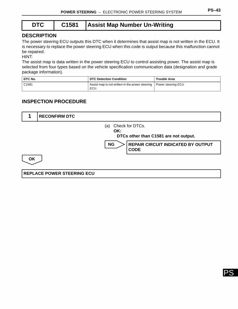
DESCRIPTIONThe power steering ECU outputs this DTC when it determines that assist map is not written in the ECU. It is necessary to replace the power steering ECU when this code is output because this malfunction cannot be repaired.HINT:The assist map is data written in the power steering ECU to control assisting power. The assist map is selected from four types based on the vehicle specification communication data (designation and grade package information).
INSPECTION PROCEDURE
(a) Check for DTCs.OK:
DTCs other than C1581 are not output.
NG
OK
DTC C1581 Assist Map Number Un-Writing
DTC No. DTC Detection Condition Trouble Area
C1581 Assist map is not written in the power steering ECU.
Power steering ECU
1 RECONFIRM DTC
REPAIR CIRCUIT INDICATED BY OUTPUT CODE
REPLACE POWER STEERING ECU
PS–44 POWER STEERING – ELECTRONIC POWER STEERING SYSTEM
PS
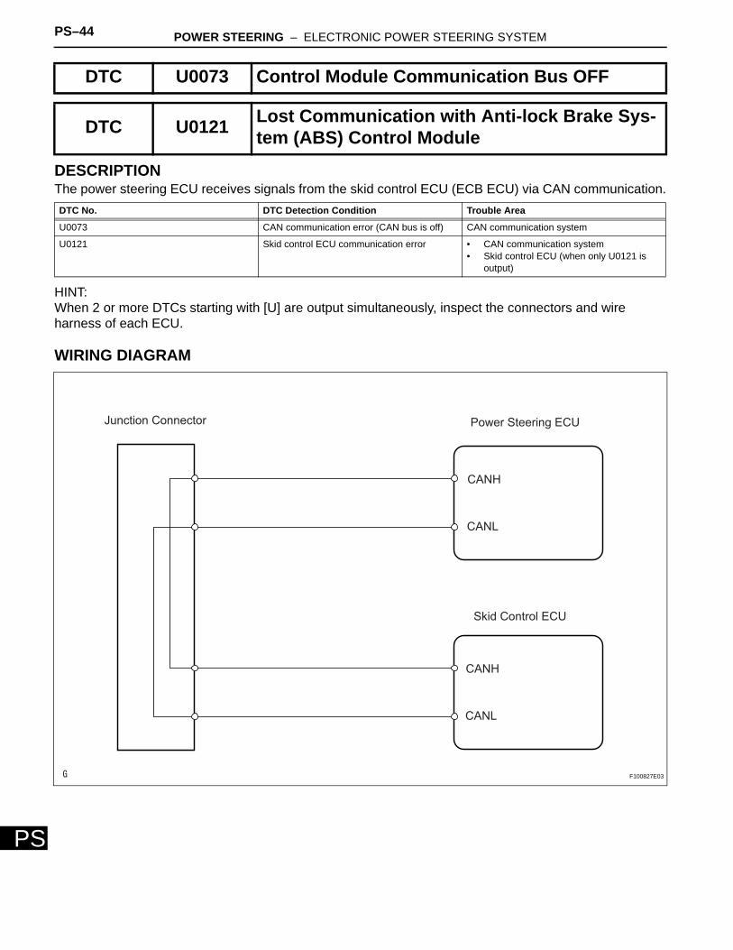
DESCRIPTIONThe power steering ECU receives signals from the skid control ECU (ECB ECU) via CAN communication.
HINT:When 2 or more DTCs starting with [U] are output simultaneously, inspect the connectors and wire harness of each ECU.
WIRING DIAGRAM
DTC U0073 Control Module Communication Bus OFF
DTC U0121 Lost Communication with Anti-lock Brake Sys-tem (ABS) Control Module
DTC No. DTC Detection Condition Trouble Area
U0073 CAN communication error (CAN bus is off) CAN communication system
U0121 Skid control ECU communication error • CAN communication system• Skid control ECU (when only U0121 is
output)
Junction Connector Power Steering ECU
Skid Control ECU
CANH
CANL
CANH
CANL
F100827E03
POWER STEERING – ELECTRONIC POWER STEERING SYSTEM PS–45
PS
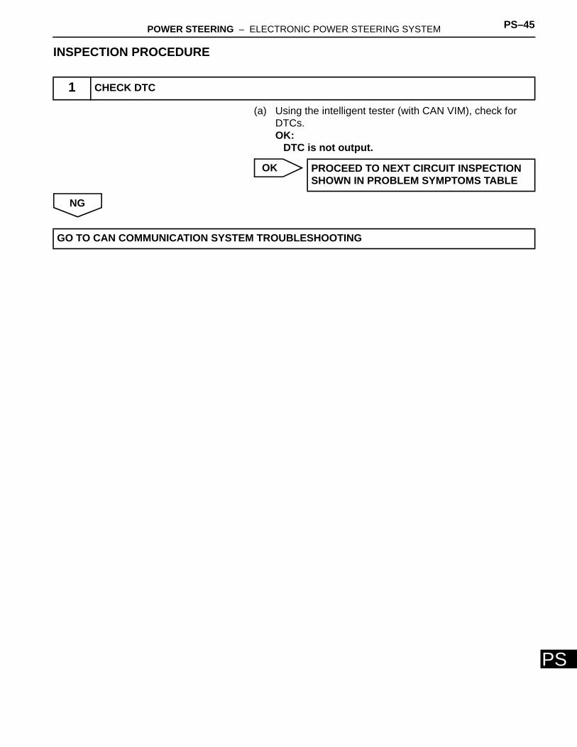
INSPECTION PROCEDURE
(a) Using the intelligent tester (with CAN VIM), check for DTCs.OK:
DTC is not output.
OK
NG
1 CHECK DTC
PROCEED TO NEXT CIRCUIT INSPECTION SHOWN IN PROBLEM SYMPTOMS TABLE
GO TO CAN COMMUNICATION SYSTEM TROUBLESHOOTING
PS–46 POWER STEERING – ELECTRONIC POWER STEERING SYSTEM
PS
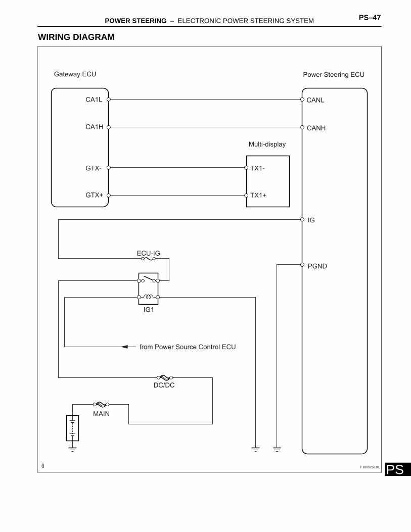
DESCRIPTIONThe troubleshooting procedure for a situation when no DTCs are output but a PS warning is always indicated is specified here. The PS warning remains on when there is an open in the IG circuit that inputs power source voltage to the power steering ECU.
PS Warning is Always Shown on Multi-Display
POWER STEERING – ELECTRONIC POWER STEERING SYSTEM PS–47
PS
WIRING DIAGRAM
IG1
DC/DC
ECU-IG
MAIN
PGND
IG
CANL
CANH
TX1-
TX1+
Multi-display
Power Steering ECU
CA1L
CA1H
GTX-
GTX+
Gateway ECU
from Power Source Control ECU
F100925E01
PS–48 POWER STEERING – ELECTRONIC POWER STEERING SYSTEM
PS
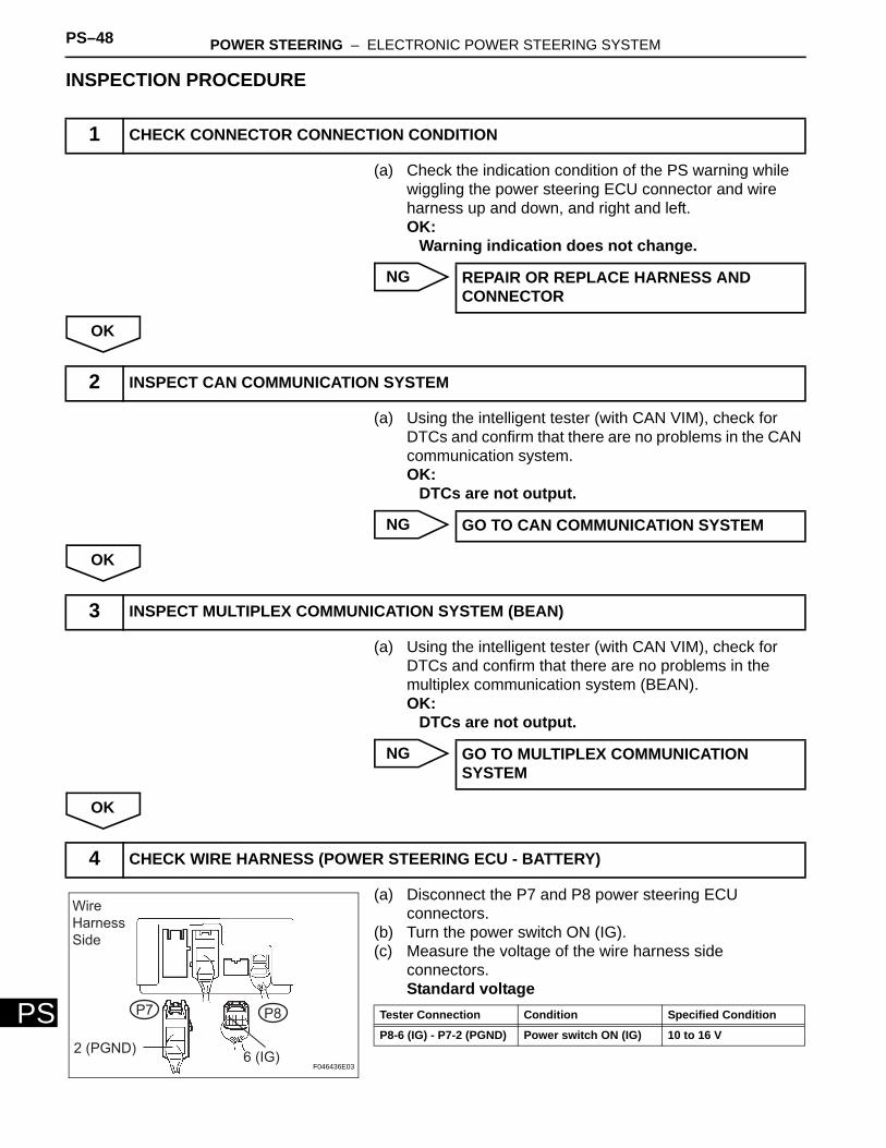
INSPECTION PROCEDURE
(a) Check the indication condition of the PS warning while wiggling the power steering ECU connector and wire harness up and down, and right and left.OK:
Warning indication does not change.
NG
OK
(a) Using the intelligent tester (with CAN VIM), check for DTCs and confirm that there are no problems in the CAN communication system.OK:
DTCs are not output.
NG
OK
(a) Using the intelligent tester (with CAN VIM), check for DTCs and confirm that there are no problems in the multiplex communication system (BEAN).OK:
DTCs are not output.
NG
OK
(a) Disconnect the P7 and P8 power steering ECU connectors.
(b) Turn the power switch ON (IG).(c) Measure the voltage of the wire harness side
connectors.Standard voltage
1 CHECK CONNECTOR CONNECTION CONDITION
REPAIR OR REPLACE HARNESS AND CONNECTOR
2 INSPECT CAN COMMUNICATION SYSTEM
GO TO CAN COMMUNICATION SYSTEM
3 INSPECT MULTIPLEX COMMUNICATION SYSTEM (BEAN)
GO TO MULTIPLEX COMMUNICATION SYSTEM
4 CHECK WIRE HARNESS (POWER STEERING ECU - BATTERY)
2 (PGND)6 (IG)
P7 P8
Wire
Harness
Side
F046436E03
Tester Connection Condition Specified Condition
P8-6 (IG) - P7-2 (PGND) Power switch ON (IG) 10 to 16 V
POWER STEERING – ELECTRONIC POWER STEERING SYSTEM PS–49
PS
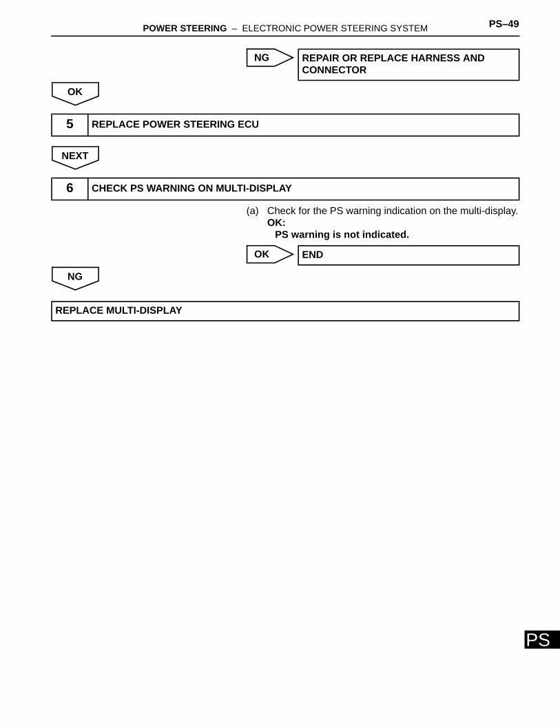
NG
OK
NEXT
(a) Check for the PS warning indication on the multi-display.OK:
PS warning is not indicated.
OK
NG
REPAIR OR REPLACE HARNESS AND CONNECTOR
5 REPLACE POWER STEERING ECU
6 CHECK PS WARNING ON MULTI-DISPLAY
END
REPLACE MULTI-DISPLAY
PS–48 POWER STEERING – STEERING GEAR
PS
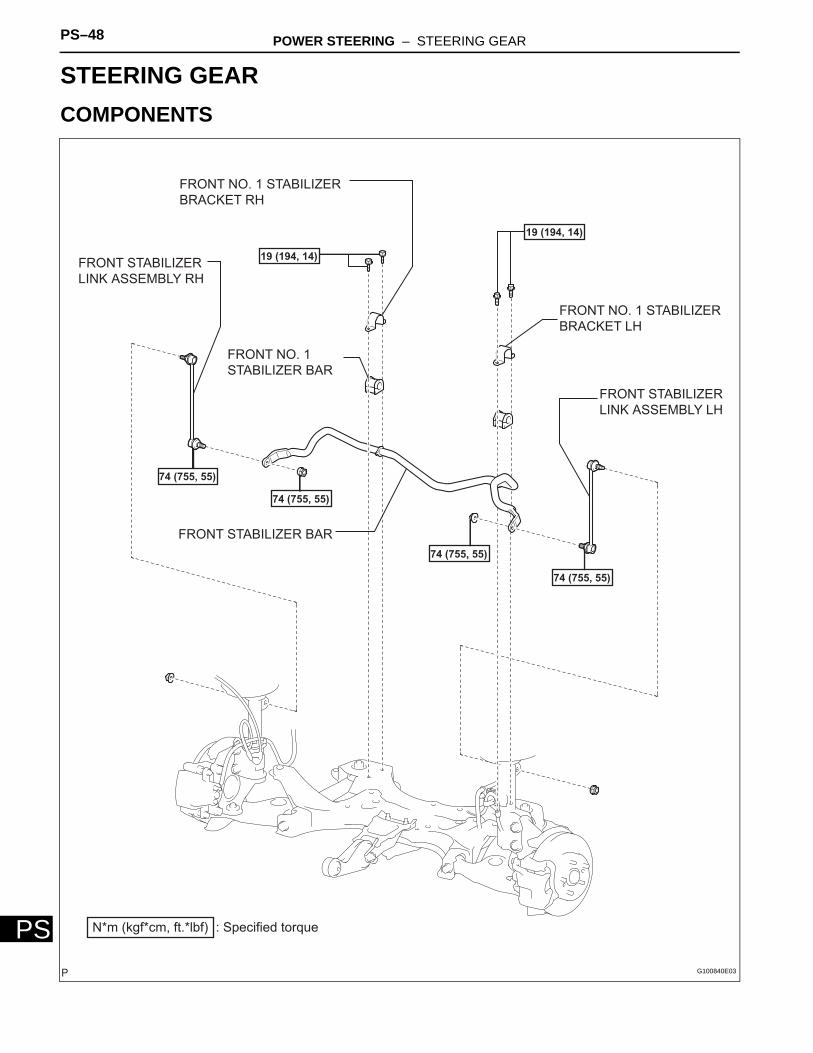
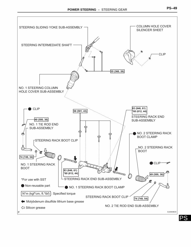
STEERINGPOWER STEERINGSTEERING GEARCOMPONENTS
: Specified torqueN*m (kgf*cm, ft.*lbf)
19 (194, 14)FRONT STABILIZER
LINK ASSEMBLY RH
FRONT NO. 1
STABILIZER BAR
74 (755, 55)
74 (755, 55)
74 (755, 55)
74 (755, 55)
FRONT STABILIZER BAR
19 (194, 14)
FRONT STABILIZER
LINK ASSEMBLY LH
FRONT NO. 1 STABILIZER
BRACKET LH
FRONT NO. 1 STABILIZER
BRACKET RH
G100840E03
POWER STEERING – STEERING GEAR PS–49
PS
STEERING SLIDING YOKE SUB-ASSEMBLY
STEERING INTERMEDIATE SHAFT
COLUMN HOLE COVER
SILENCER SHEET
CLIP
Non-reusable part
: Specified torqueN*m (kgf*cm, ft.*lbf)
35 (360, 26)
58 (591, 43)CLIP
49 (500, 36)
74 (749, 54)
STEERING RACK BOOT CLIP
*For use with SST
Molybdenum disulfide lithium base grease
Silicon grease
STEERING RACK END SUB-ASSEMBLY
83 (846, 61)
*60 (612, 44)
74 (749, 54)
49 (500, 36)
STEERING RACK END
SUB-ASSEMBLY
83 (846, 61)
*60 (612, 44)
CLIP
STEERING RACK BOOT CLIP
NO. 1 STEERING COLUMN
HOLE COVER SUB-ASSEMBLY
NO. 1 STEERING RACK
BOOT
NO. 1 STEERING RACK BOOT CLAMP
NO. 2 STEERING RACK
BOOT
NO. 2 STEERING RACK
BOOT CLAMP
NO. 1 TIE ROD END
SUB-ASSEMBLY
NO. 2 TIE ROD END SUB-ASSEMBLY
G100839E04
PS–50 POWER STEERING – STEERING GEAR
PS
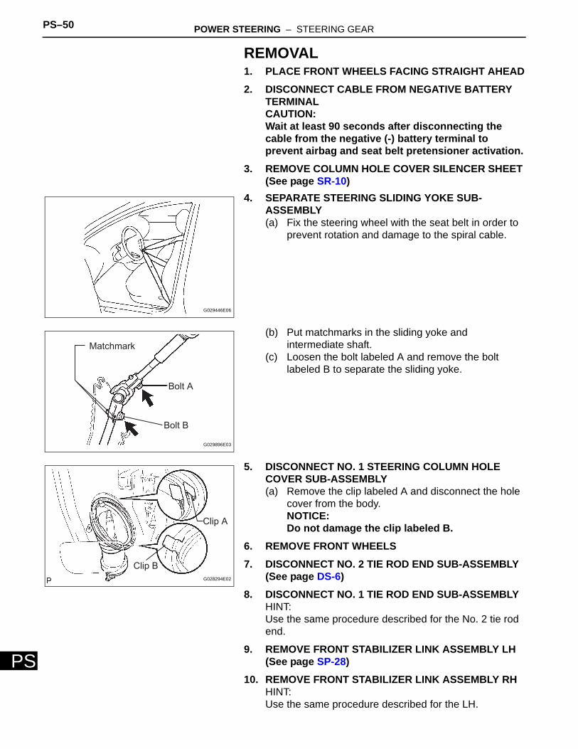
REMOVAL1. PLACE FRONT WHEELS FACING STRAIGHT AHEAD2. DISCONNECT CABLE FROM NEGATIVE BATTERY
TERMINALCAUTION:Wait at least 90 seconds after disconnecting the cable from the negative (-) battery terminal to prevent airbag and seat belt pretensioner activation.
3. REMOVE COLUMN HOLE COVER SILENCER SHEET (See page SR-10)
4. SEPARATE STEERING SLIDING YOKE SUB-ASSEMBLY(a) Fix the steering wheel with the seat belt in order to
prevent rotation and damage to the spiral cable.
(b) Put matchmarks in the sliding yoke and intermediate shaft.
(c) Loosen the bolt labeled A and remove the bolt labeled B to separate the sliding yoke.
5. DISCONNECT NO. 1 STEERING COLUMN HOLE COVER SUB-ASSEMBLY(a) Remove the clip labeled A and disconnect the hole
cover from the body.NOTICE:Do not damage the clip labeled B.
6. REMOVE FRONT WHEELS7. DISCONNECT NO. 2 TIE ROD END SUB-ASSEMBLY
(See page DS-6)8. DISCONNECT NO. 1 TIE ROD END SUB-ASSEMBLY
HINT:Use the same procedure described for the No. 2 tie rod end.
9. REMOVE FRONT STABILIZER LINK ASSEMBLY LH (See page SP-28)
10. REMOVE FRONT STABILIZER LINK ASSEMBLY RHHINT:Use the same procedure described for the LH.
G029446E06
Matchmark
Bolt A
Bolt B
G029896E03
Clip A
Clip B
G028294E02
POWER STEERING – STEERING GEAR PS–51
PS
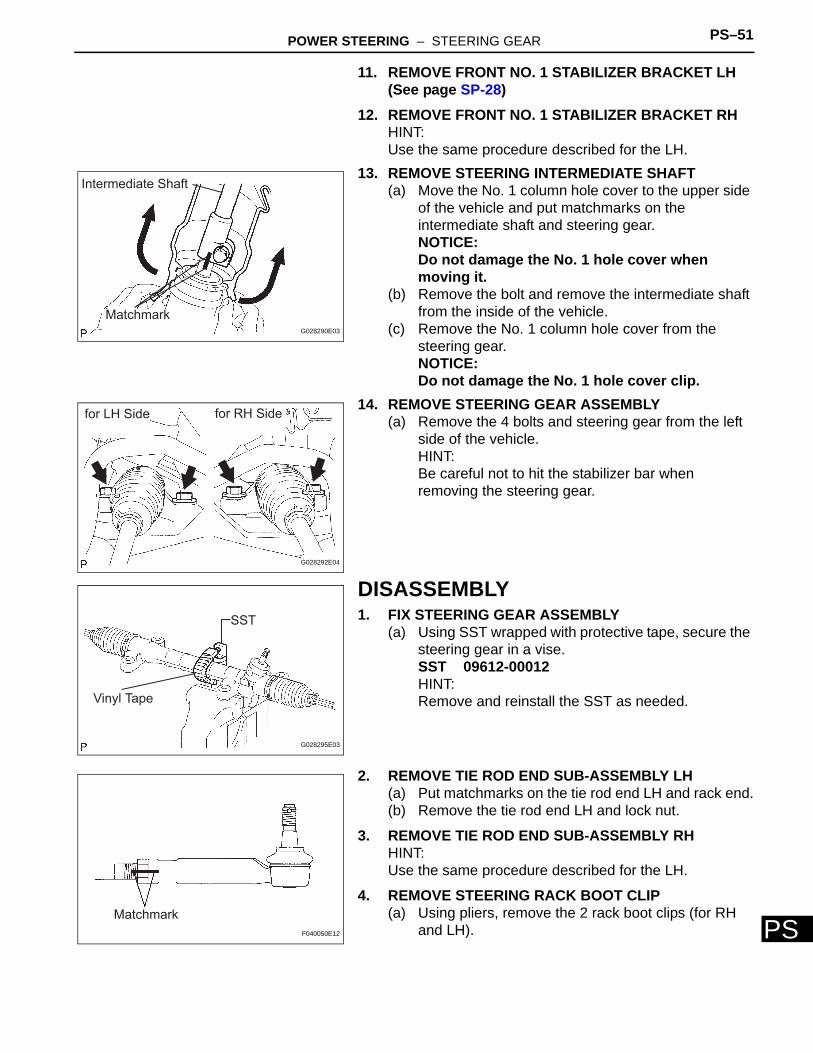
11. REMOVE FRONT NO. 1 STABILIZER BRACKET LH (See page SP-28)
12. REMOVE FRONT NO. 1 STABILIZER BRACKET RHHINT:Use the same procedure described for the LH.
13. REMOVE STEERING INTERMEDIATE SHAFT(a) Move the No. 1 column hole cover to the upper side
of the vehicle and put matchmarks on the intermediate shaft and steering gear.NOTICE:Do not damage the No. 1 hole cover when moving it.
(b) Remove the bolt and remove the intermediate shaft from the inside of the vehicle.
(c) Remove the No. 1 column hole cover from the steering gear.NOTICE:Do not damage the No. 1 hole cover clip.
14. REMOVE STEERING GEAR ASSEMBLY(a) Remove the 4 bolts and steering gear from the left
side of the vehicle.HINT:Be careful not to hit the stabilizer bar when removing the steering gear.
DISASSEMBLY1. FIX STEERING GEAR ASSEMBLY
(a) Using SST wrapped with protective tape, secure the steering gear in a vise.SST 09612-00012HINT:Remove and reinstall the SST as needed.
2. REMOVE TIE ROD END SUB-ASSEMBLY LH(a) Put matchmarks on the tie rod end LH and rack end.(b) Remove the tie rod end LH and lock nut.
3. REMOVE TIE ROD END SUB-ASSEMBLY RHHINT:Use the same procedure described for the LH.
4. REMOVE STEERING RACK BOOT CLIP(a) Using pliers, remove the 2 rack boot clips (for RH
and LH).
Intermediate Shaft
MatchmarkG028290E03
for LH Side for RH Side
G028292E04
SST
Vinyl Tape
G028295E03
Matchmark
F040050E12
PS–52 POWER STEERING – STEERING GEAR
PS
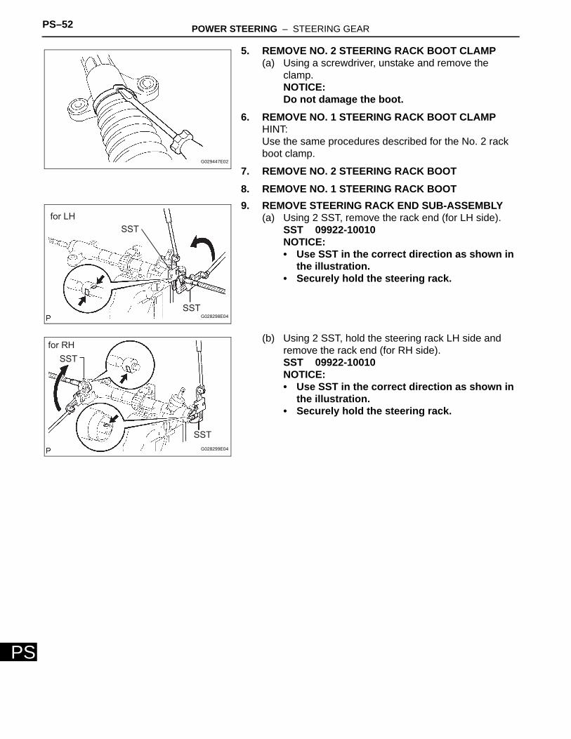
5. REMOVE NO. 2 STEERING RACK BOOT CLAMP(a) Using a screwdriver, unstake and remove the
clamp.NOTICE:Do not damage the boot.
6. REMOVE NO. 1 STEERING RACK BOOT CLAMPHINT:Use the same procedures described for the No. 2 rack boot clamp.
7. REMOVE NO. 2 STEERING RACK BOOT8. REMOVE NO. 1 STEERING RACK BOOT9. REMOVE STEERING RACK END SUB-ASSEMBLY
(a) Using 2 SST, remove the rack end (for LH side).SST 09922-10010NOTICE:• Use SST in the correct direction as shown in
the illustration.• Securely hold the steering rack.
(b) Using 2 SST, hold the steering rack LH side and remove the rack end (for RH side).SST 09922-10010NOTICE:• Use SST in the correct direction as shown in
the illustration.• Securely hold the steering rack.
G029447E02
for LH
SST
SSTG028298E04
for RH
SST
SST
G028299E04
POWER STEERING – STEERING GEAR PS–53
PS
INSPECTION1. INSPECT TIE ROD END SUB-ASSEMBLY LH
(a) Secure the tie rod end LH boll join in a vise through aluminum plates.NOTICE:Do not overtighten the vise.
(b) Install the castle nut to the stud bolt.(c) Flip the ball joint back and forth 5 times or more.(d) Set a torque wrench to the nut, turn the ball joint
continuously at a rate of 3 to 5 seconds per turn, and check the turning torque on the 5th turn.Standard turning torque:
2.0 N*m (20.4 kgf*cm, 18 in. lbf) or lessIf turning torque is out of specification, replace the tie rod end LH with a new one.
2. INSPECT TIE ROD END SUB-ASSEMBLY RHHINT:Use the same procedures described for the LH side.
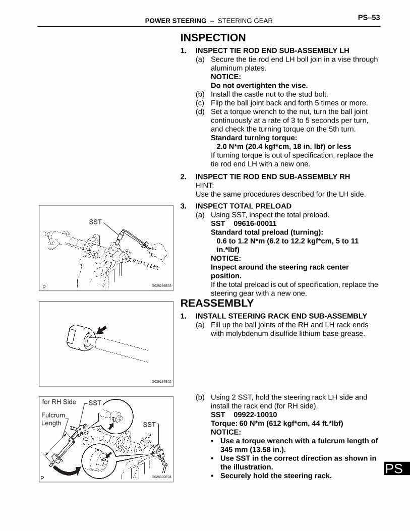
3. INSPECT TOTAL PRELOAD(a) Using SST, inspect the total preload.
SST 09616-00011Standard total preload (turning):
0.6 to 1.2 N*m (6.2 to 12.2 kgf*cm, 5 to 11 in.*lbf)
NOTICE:Inspect around the steering rack center position.If the total preload is out of specification, replace the steering gear with a new one.
REASSEMBLY1. INSTALL STEERING RACK END SUB-ASSEMBLY
(a) Fill up the ball joints of the RH and LH rack ends with molybdenum disulfide lithium base grease.
(b) Using 2 SST, hold the steering rack LH side and install the rack end (for RH side).SST 09922-10010Torque: 60 N*m (612 kgf*cm, 44 ft.*lbf)NOTICE:• Use a torque wrench with a fulcrum length of
345 mm (13.58 in.).• Use SST in the correct direction as shown in
the illustration.• Securely hold the steering rack.
SST
G028296E03
G029137E02
for RH Side SST
Fulcrum
Length SST
G028300E04
PS–54 POWER STEERING – STEERING GEAR
PS
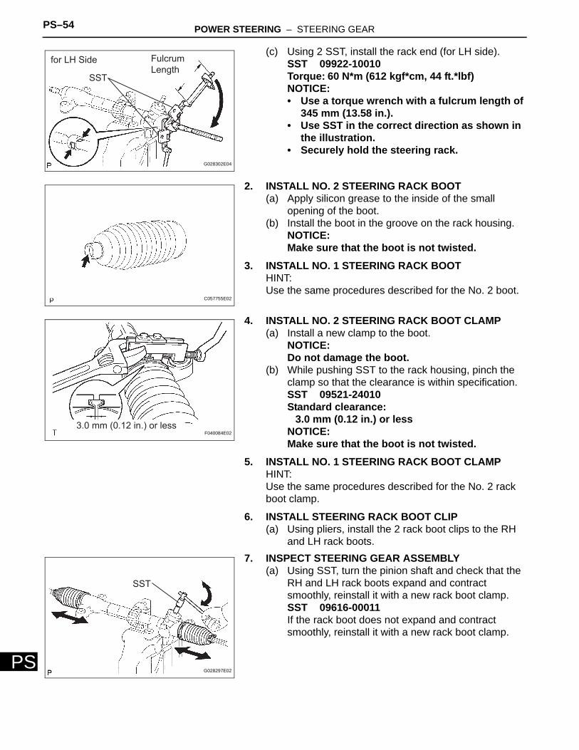
(c) Using 2 SST, install the rack end (for LH side).SST 09922-10010Torque: 60 N*m (612 kgf*cm, 44 ft.*lbf)NOTICE:• Use a torque wrench with a fulcrum length of
345 mm (13.58 in.).• Use SST in the correct direction as shown in
the illustration.• Securely hold the steering rack.
2. INSTALL NO. 2 STEERING RACK BOOT(a) Apply silicon grease to the inside of the small
opening of the boot.(b) Install the boot in the groove on the rack housing.
NOTICE:Make sure that the boot is not twisted.
3. INSTALL NO. 1 STEERING RACK BOOTHINT:Use the same procedures described for the No. 2 boot.
4. INSTALL NO. 2 STEERING RACK BOOT CLAMP(a) Install a new clamp to the boot.
NOTICE:Do not damage the boot.
(b) While pushing SST to the rack housing, pinch the clamp so that the clearance is within specification.SST 09521-24010Standard clearance:
3.0 mm (0.12 in.) or lessNOTICE:Make sure that the boot is not twisted.
5. INSTALL NO. 1 STEERING RACK BOOT CLAMPHINT:Use the same procedures described for the No. 2 rack boot clamp.
6. INSTALL STEERING RACK BOOT CLIP(a) Using pliers, install the 2 rack boot clips to the RH
and LH rack boots.7. INSPECT STEERING GEAR ASSEMBLY
(a) Using SST, turn the pinion shaft and check that the RH and LH rack boots expand and contract smoothly, reinstall it with a new rack boot clamp.SST 09616-00011If the rack boot does not expand and contract smoothly, reinstall it with a new rack boot clamp.
for LH Side
SST
Fulcrum
Length
G028302E04
C057755E02
3.0 mm (0.12 in.) or lessF040084E02
SST
G028297E02
POWER STEERING – STEERING GEAR PS–55
PS
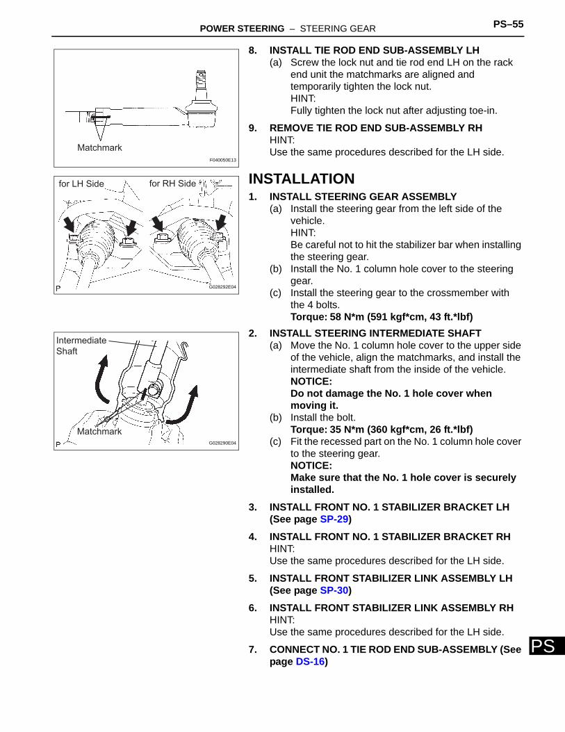
8. INSTALL TIE ROD END SUB-ASSEMBLY LH(a) Screw the lock nut and tie rod end LH on the rack
end unit the matchmarks are aligned and temporarily tighten the lock nut.HINT:Fully tighten the lock nut after adjusting toe-in.
9. REMOVE TIE ROD END SUB-ASSEMBLY RHHINT:Use the same procedures described for the LH side.
INSTALLATION1. INSTALL STEERING GEAR ASSEMBLY
(a) Install the steering gear from the left side of the vehicle.HINT:Be careful not to hit the stabilizer bar when installing the steering gear.
(b) Install the No. 1 column hole cover to the steering gear.
(c) Install the steering gear to the crossmember with the 4 bolts.Torque: 58 N*m (591 kgf*cm, 43 ft.*lbf)
2. INSTALL STEERING INTERMEDIATE SHAFT(a) Move the No. 1 column hole cover to the upper side
of the vehicle, align the matchmarks, and install the intermediate shaft from the inside of the vehicle.NOTICE:Do not damage the No. 1 hole cover when moving it.
(b) Install the bolt.Torque: 35 N*m (360 kgf*cm, 26 ft.*lbf)
(c) Fit the recessed part on the No. 1 column hole cover to the steering gear.NOTICE:Make sure that the No. 1 hole cover is securely installed.
3. INSTALL FRONT NO. 1 STABILIZER BRACKET LH (See page SP-29)
4. INSTALL FRONT NO. 1 STABILIZER BRACKET RHHINT:Use the same procedures described for the LH side.
5. INSTALL FRONT STABILIZER LINK ASSEMBLY LH (See page SP-30)
6. INSTALL FRONT STABILIZER LINK ASSEMBLY RHHINT:Use the same procedures described for the LH side.
7. CONNECT NO. 1 TIE ROD END SUB-ASSEMBLY (See page DS-16)
Matchmark
F040050E13
for LH Side for RH Side
G028292E04
Intermediate
Shaft
MatchmarkG028290E04
PS–56 POWER STEERING – STEERING GEAR
PS
8. CONNECT NO. 2 TIE ROD END SUB-ASSEMBLYHINT:Use the same procedures described for the No. 1 tie rod end.
9. INSTALL FRONT WHEELTorque: 103 N*m (1,050 kgf*cm, 76 ft.*lbf)
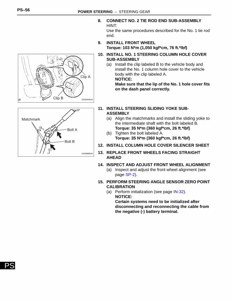
10. INSTALL NO. 1 STEERING COLUMN HOLE COVER SUB-ASSEMBLY(a) Install the clip labeled B to the vehicle body and
install the No. 1 column hole cover to the vehicle body with the clip labeled A.NOTICE:Make sure that the lip of the No. 1 hole cover fits on the dash panel correctly.
11. INSTALL STEERING SLIDING YOKE SUB-ASSEMBLY(a) Align the matchmarks and install the sliding yoke to
the intermediate shaft with the bolt labeled B.Torque: 35 N*m (360 kgf*cm, 26 ft.*lbf)
(b) Tighten the bolt labeled A.Torque: 35 N*m (360 kgf*cm, 26 ft.*lbf)
12. INSTALL COLUMN HOLE COVER SILENCER SHEET13. REPLACE FRONT WHEELS FACING STRAIGHT
AHEAD14. INSPECT AND ADJUST FRONT WHEEL ALIGNMENT
(a) Inspect and adjust the front wheel alignment (see page SP-2).
15. PERFORM STEERING ANGLE SENSOR ZERO POINT CALIBRATION(a) Perform initialization (see page IN-32).
NOTICE:Certain systems need to be initialized after disconnecting and reconnecting the cable from the negative (-) battery terminal.
Clip A
Clip B G028294E03
Bolt A
Bolt B
Matchmark
G029896E04