Embed Size (px)
Citation preview

OPERATING INSTRUCTIONS
POwER SUPPly mANAGER
VX-3000DS CEVX-3000DS CE-GB
Thank you for purchasing TOA’s Power Supply Manager.Please carefully follow the instructions in this manual to ensure long, trouble-free use of your equipment.
2
TABlE OF CONTENTS
1. SAFETy PRECAUTIONS ............................................................................. 3
2. FEATURES ............................................................................................................ 4
3. NOmENClATURE AND FUNCTIONS ................................................. 5Front ............................................................................................................................. 5Front (with the front panel removed) ............................................................................ 6Rear ............................................................................................................................. 7
4. INSTAllATION .................................................................................................. 84.1. Installing the VX-3000DS in the Cabinet Rack ...................................................... 84.2. Battery Installation ................................................................................................ 8
5. CONNECTIONS ............................................................................................... 135.1. Connecting the VX-3000DS to VX-2000 System ................................................ 135.2. Connecting the VX-3000DS to SX-2000 System ................................................ 145.3. Connecting the VX-3000DS to VM-3000 System ............................................... 17
6. CABlE USAGE TABlE ............................................................................... 21
7. SwITCHING OFF SySTEm POwER (DC) ....................................... 22
8. BlOCk DIAGRAm ......................................................................................... 23
9. APPENDIX: Recommendations to the Power Supply Installation ............................................................................. 24
10. SPECIFICATIONS ........................................................................................ 29 Accessories .............................................................................................................. 29
3
1. SAFETy PRECAUTIONS• Before installationoruse,besure tocarefully readall the instructions in thissection forcorrectandsafe
operation.• Besuretofollowalltheprecautionaryinstructionsinthissection,whichcontainimportantwarningsand/or
cautions regarding safety.• Afterreading,keepthismanualhandyforfuturereference.
Safety Symbol and message Conventions Safety symbols and messages described below are used in this manual to prevent bodily injury and property damage which could result from mishandling. Before operating your product, read this manual first andunderstand the safety symbols and messages so you are thoroughly aware of the potential safety hazards.
Indicates a potentially hazardous situation which, if mishandled, could result in death or serious personal injury.
Indicates a potentially hazardous situation which, if mishandled, could resultinmoderateorminorpersonalinjury,and/orpropertydamage.
wARNINGCAUTION
when Installing the Unit
• Donotexpose theunit to rainor anenvironmentwhere it may be splashed by water or other liquids, asdoingsomayresultinfireorelectricshock.
• Use the unit only with the voltage specified ontheunit.Usingavoltagehigherthanthatwhichisspecifiedmayresultinfireorelectricshock.
• Do not cut, kink, otherwise damage nor modifythe power supply cord. In addition, avoid using the powercordincloseproximitytoheaters,andneverplace heavy objects -- including the unit itself -- on the power cord, as doing somay result in fire orelectric shock.
when the Unit is in Use
• Should the following irregularity be found duringuse, immediately switch off the main power, (or circuit breaker), disconnect the battery, and contact your nearest TOA dealer. Make no further attempt to operate the unit in this condition as this may causefireorelectricshock.
· If you detect smoke or a strange smell coming from the unit.
· If water or any metallic object gets into the unit · If the unit falls, or the unit case breaks · Ifthepowersupplycordisdamaged(exposureof
the core, disconnection, etc.)· If it is malfunctioning (no tone sounds.)
• Topreventafireorelectricshock,neveropentheunit case nor modify the unit. Refer all servicing to qualifiedservicepersonnel.
• Do not place cups, bowls, or other containers ofliquid or metallic objects on top of the unit. If they accidentallyspillintotheunit,thismaycauseafireor electric shock.
• Donotinsertnordropmetallicobjectsorflammablematerials in the ventilation slots of the unit’s cover asthismayresultinfireorelectricshock.
• Donot touchapowersupplyplugduring thunderand lightning, as this may result in electric shock.
• When replacing the AC fuse, be sure to use thesuppliedone(T8AH).Usinganyother fuse thansuppliedmaycausefireorelectricshock.
• Handleorusethebatteriesproperly. Doingotherwisemay cause leakageor explosionof thebatteries,resulting inafire,personal injury,damage to peripheral equipment, or contamination of environment.
when Installing the Unit
• Never plug in nor remove the power supply plugwith wet hands, as doing so may cause electric shock.
• Whenunpluggingthepowersupplycord,besuretograsp the power supply plug; never pull on the cord itself. Operating the unit with a damaged power supplycordmaycauseafireorelectricshock.
• Donotblocktheventilationslotsintheunit’scover.Doing so may cause heat to build up inside the unit andresultinfire.
wARNING
CAUTION
4
• Avoidinstallingtheunitinhumidordustylocations,inlocationsexposedtothedirectsunlight,neartheheaters, or in locations generating sooty smoke or steamas doing otherwisemay result in fire orelectric shock.
• System units (except remote microphones) aredesignedexclusivelytobemountedinanequipmentrack. Be sure observe the following instructions when rack-mounting the unit. Failure to do so may causeafireorpersonalinjury.· Installtheequipmentrackonastable,hardfloor.Fixitwithanchorboltsortakeotherarrangementsto prevent it from falling down.
· The supplied rack-mounting screws can be used for the TOA equipment rack only. Do not use them for other racks.
• Note correct polarity (positive and negativeorientation) when connecting the power supply cord. Reversed polarity connections will cause damage to the system.
when the Unit is in Use
• Usethespecifiedpowersupplyunitforthesystem.Note that theuseofotherpowersupplyunitmaycauseafire.
• Make sure to observe the following handlingprecautions so that a fire or personal injury doesnotresultfromleakageorexplosionofthebattery.
· Do not short, disassemble, heat nor put the battery intoafire.
· Avoid using both new and old batteries together.· Neverchargebatteriesofthetypewhicharenot
rechargeable. · Do not solder a battery directly.· Besuretousethespecifiedtypeofbatteries.·Note correct polarity (positive and negative
orientation) when connecting a battery to the unit.· Avoid locations exposed to the direct sunlight,
high temperature and high humidity when storing batteries.
2. FEATURES•InternaldualpowersupplysuppliesDCpowertoindividualcomponents.
•AutomaticallyswitchestothebackuppowersupplywhentheACMainspowersupplyisinterrupted.
•Detectschargingcircuitryorbatteryfailures,andtransmitsfailuresignalstotheDSLINKoftheTOAVoiceEvacuation Systems (VX-2000, SX-2000, and VM-3000).
•Keepsa 2 x 12V sealed lead-acid battery chargedwhilemaintaining temperature compensation for thecharging voltage.
•Automaticallydisconnectsthebatteryifitsvoltagereachesadischargefinallevel.
5
3. NOmENClATURE AND FUNCTIONS[Front]
1 2 3
4 5 6
AC POWER BATTERYIN1
IN2
POWER
CONNECT
CONDITION
POWER SUPPLY MANAGER VX-3000DS
CHECK
CHARGING
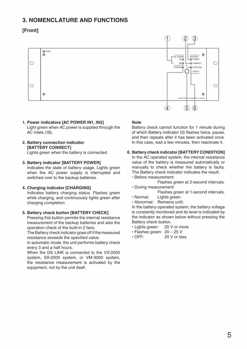
1. Power indicators [AC POwER IN1, IN2]LightgreenwhenACpowerissuppliedthroughtheAC inlets (18).
2. Battery connection indicator [BATTERy CONNECT]Lightsgreenwhenthebatteryisconnected.
3. Battery indicator [BATTERy POwER]Indicatesthestateofbatteryusage.Lightsgreenwhen the AC power supply is interrupted and switched over to the backup batteries.
4. Charging indicator [CHARGING]Indicates battery charging status. Flashes green while charging, and continuously lights green after charging completion.
5. Battery check button [BATTERy CHECk]Pressing this button permits the internal resistance measurement of the backup batteries and also the operation check of the built-in 2 fans.The Battery check indicator goes off if the measured resistanceexceedsthespecifiedvalue.In automatic mode, the unit performs battery check every 3 and a half hours.When theDSLINK isconnected to theVX-2000system, SX-2000 system, or VM-3000 system, the resistance measurement is activated by the equipment, not by the unit itself.
NoteBattery check cannot function for 1 minute during ofwhichBatteryindicator(3)flashestwice,pause,and then repeats after it has been activated once. In this case, wait a few minutes, then reactivate it.
6. Battery check indicator [BATTERy CONDITION] In the AC operated system, the internal resistance value of the battery is measured automatically or manually to check whether the battery is faulty. The Battery check indicator indicates the result.•Beforemeasurement: Flashes green at 2-second intervals.•Duringmeasurement: Flashes green at 1-second intervals.•Normal: Lightsgreen.•Abnormal: Remainsunlit.In the battery-operated system, the battery voltage is constantly monitored and its level is indicated by the indicator as shown below without pressing the Battery check button.•Lightsgreen: 25Vormore•Flashesgreen:20–25V•OFF: 20Vorless
6
[Fault indication]If any of the following indicators on the front panel remains unlit, the unit is judged failed. In such cases, remove the cause of the failure, and restore the unit to normal operation.•Powerindicators[ACPOWERIN1,IN2]•Batteryconnectionindicator[BATTERYCONNECT]•Chargingindicator[CHARGING]•Batterycheckindicator[BATTERYCONDITION]
NoteEvenifanyoftheseindicatorsflashes,thisdoesnotindicatemalfunction.
[Front (with the front panel removed)]
97 8
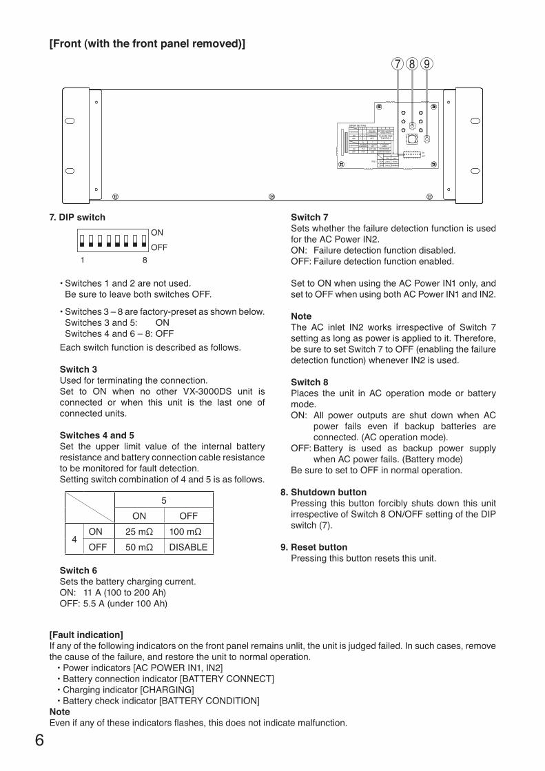
7. DIP switch
8 1
ON
OFF
•Switches1and2arenotused. Be sure to leave both switches OFF.
•Switches3–8arefactory-presetasshownbelow. Switches3and5: ON Switches4and6–8:OFFEach switch function is described as follows.
Switch 3Usedforterminatingtheconnection.Set to ON when no other VX-3000DS unit isconnected or when this unit is the last one of connected units.
Switches 4 and 5Set the upper limit value of the internal battery resistance and battery connection cable resistance to be monitored for fault detection.Setting switch combination of 4 and 5 is as follows.
5ON OFF
4ON 25mΩ 100mΩOFF 50mΩ DISABLE
Switch 6Sets the battery charging current.ON: 11A(100to200Ah)OFF:5.5A(under100Ah)
Switch 7Sets whether the failure detection function is used fortheACPowerIN2.ON: Failuredetectionfunctiondisabled.OFF:Failuredetectionfunctionenabled.
SettoONwhenusingtheACPowerIN1only,andsettoOFFwhenusingbothACPowerIN1andIN2.
NoteThe AC inlet IN2 works irrespective of Switch 7setting as long as power is applied to it. Therefore, be sure to set Switch 7 to OFF (enabling the failure detectionfunction)wheneverIN2isused.
Switch 8Places the unit in AC operation mode or battery mode.ON: All power outputs are shut down when AC
power fails even if backup batteries are connected. (AC operation mode).
OFF:Battery is used as backup power supplywhen AC power fails. (Battery mode)
Be sure to set to OFF in normal operation.
8. Shutdown buttonPressing this button forcibly shuts down this unit irrespectiveofSwitch8ON/OFFsettingoftheDIPswitch (7).
9. Reset buttonPressing this button resets this unit.
7
[Rear]
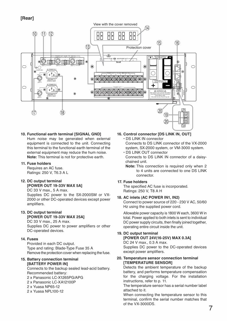
10. Functional earth terminal [SIGNAl GND]Hum noise may be generated when externalequipment is connected to the unit. Connecting this terminal to the functional earth terminal of the externalequipmentmayreducethehumnoise.Note: This terminal is not for protective earth.
11. Fuse holdersRequires an AC fuse.Ratings:250V,T6.3AL
12. DC output terminal [POwER OUT 19-33V mAX 5A]
DC33Vmax.,5Amax.Supplies DC power to the SX-2000SM or VX-2000orotherDC-operateddevicesexceptpoweramplifiers.
13. DC output terminal [POwER OUT 19-33V mAX 25A]
DC33Vmax.,25Amax.SuppliesDCpower topoweramplifiersorotherDC-operated devices.
14. FusesProvided in each DC output.Typeandrating:Blade-TypeFuse35ARemove the protection cover when replacing the fuse.
15. Battery connection terminal [BATTERy POwER IN]
Connects to the backup sealed lead-acid battery.Recommendedbattery:2xPanasonicLC-X1265PG/APG2xPanasonicLC-XA12100P2xYuasaNP65-122xYuasaNPL100-12
16. Control connector [DS lINk IN, OUT]•DSLINKINconnectorConnectstoDSLINKconnectoroftheVX-2000system, SX-2000 system, or VM-3000 system.•DSLINKOUTconnectorConnects toDSLINKINconnectorofadaisy-chainedunit.Note: This connection is required only when 2
to4unitsareconnectedtooneDSLINKconnector.
17. Fuse holdersThespecifiedACfuseisincorporated.Ratings:250V,T8AH
18. AC inlets (AC POwER IN1, IN2)Connecttopowersourceof220-230VAC,50/60Hz using the supplied power cord.Allowablepowercapacityis1800Weach,3600Wintotal. Power applied to both inlets is sent to individual DCpowersupplycircuits,thenfinallyjoinedtogether,operating entire circuit inside the unit.
19. DC output terminal [POwER OUT 24V(16-25V) mAX 0.3A]
DC24Vmax.,0.3Amax.Supplies DC power to the DC-operated devices exceptpoweramplifiers.
20. Temperature sensor connection terminal [TEmPERATURE SENSOR]Detects the ambient temperature of the backup battery, and performs temperature compensation for the charging voltage. For the installation instructions, refer to p. 11.The temperature sensor has a serial number label attached to it. Whenconnectingthetemperaturesensortothisterminal,confirmtheserialnumbermatchesthatof the VX-3000DS.
1016
Protection cover
12
17
1513
11
18
TEM
PER
ATU
RE
SEN
SOR
24V(
16-2
5V)
POW
ER O
UT
MAX
0.3
A
INO
UT
DS
LIN
K
View with the cover removed14
2019
20
8
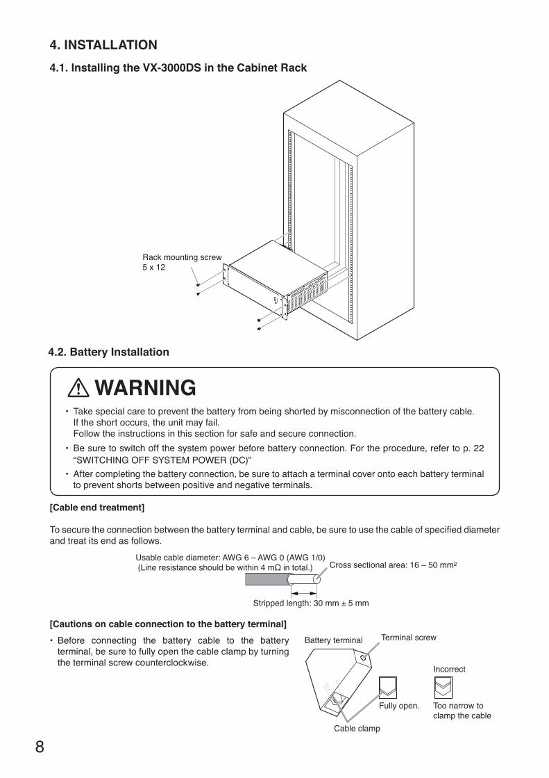
4. INSTAllATION4.1. Installing the VX-3000DS in the Cabinet Rack
4.2. Battery Installation
• Takespecialcaretopreventthebatteryfrombeingshortedbymisconnectionofthebatterycable. If the short occurs, the unit may fail. Follow the instructions in this section for safe and secure connection.• Besuretoswitchoffthesystempowerbeforebatteryconnection.Fortheprocedure,referto p. 22 “SWITCHINGOFFSYSTEMPOWER(DC)”
• Aftercompletingthebatteryconnection,besuretoattachaterminalcoverontoeachbatteryterminalto prevent shorts between positive and negative terminals.
[Cable end treatment]
Tosecuretheconnectionbetweenthebatteryterminalandcable,besuretousethecableofspecifieddiameterand treat its end as follows.
Usable cable diameter: AWG 6 – AWG 0 (AWG 1/0) (Line resistance should be within 4 mΩ in total.)
Stripped length: 30 mm ± 5 mm
Cross sectional area: 16 – 50 mm2
[Cautions on cable connection to the battery terminal]• Before connecting the battery cable to the battery
terminal, be sure to fully open the cable clamp by turning the terminal screw counterclockwise.
Battery terminal Terminal screw
Cable clamp
Fully open. Too narrow toclamp the cable
Incorrect
Rack mounting screw5 x 12
wARNING
9
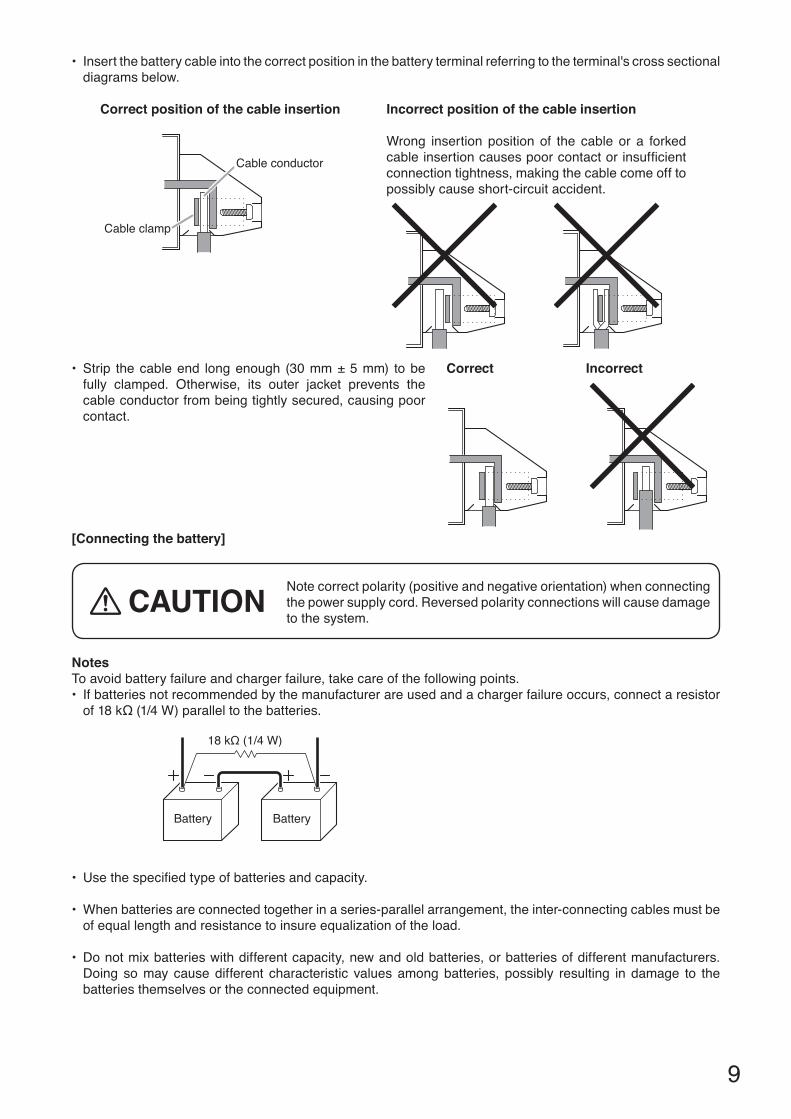
• Strip thecableend longenough (30mm±5mm) tobefully clamped. Otherwise, its outer jacket prevents the cable conductor from being tightly secured, causing poor contact.
[Connecting the battery]
Notecorrectpolarity(positiveandnegativeorientation)whenconnectingthe power supply cord. Reversed polarity connections will cause damage to the system.
• Insertthebatterycableintothecorrectpositioninthebatteryterminalreferringtotheterminal'scrosssectionaldiagrams below.
18 kΩ (1/4 W)
Battery Battery
NotesTo avoid battery failure and charger failure, take care of the following points.• Ifbatteriesnotrecommendedbythemanufacturerareusedandachargerfailureoccurs,connectaresistorof18kΩ(1/4W)paralleltothebatteries.
• Usethespecifiedtypeofbatteriesandcapacity.
• Whenbatteriesareconnectedtogetherinaseries-parallelarrangement,theinter-connectingcablesmustbeof equal length and resistance to insure equalization of the load.
• Donotmixbatterieswithdifferentcapacity,newandoldbatteries,orbatteriesofdifferentmanufacturers.Doing so may cause different characteristic values among batteries, possibly resulting in damage to the batteries themselves or the connected equipment.
CAUTION
Correct position of the cable insertion Incorrect position of the cable insertion
Wrong insertion position of the cable or a forkedcableinsertioncausespoorcontactorinsufficientconnection tightness, making the cable come off to possibly cause short-circuit accident.
Correct Incorrect
Cable conductor
Cable clamp
10
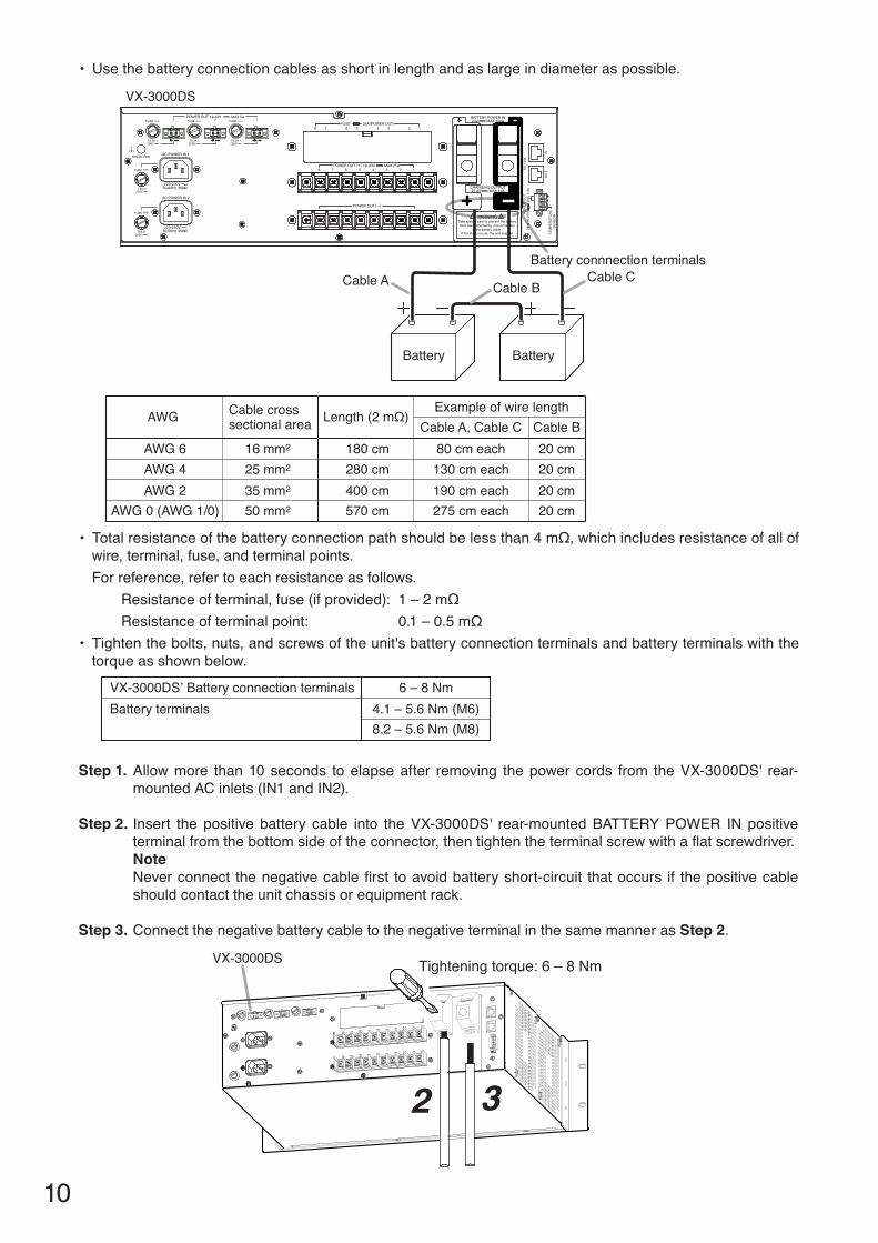
Step 1. Allowmore than10seconds toelapseafter removing thepowercords from theVX-3000DS' rear-mountedACinlets(IN1andIN2).
Step 2. Insert thepositivebattery cable into theVX-3000DS' rear-mountedBATTERYPOWER INpositiveterminalfromthebottomsideoftheconnector,thentightentheterminalscrewwithaflatscrewdriver.NoteNeverconnect thenegativecablefirst toavoidbatteryshort-circuit thatoccurs if thepositivecableshould contact the unit chassis or equipment rack.
Step 3. Connect the negative battery cable to the negative terminal in the same manner as Step 2.
VX-3000DS Tightening torque: 6 – 8 Nm
32
Cable cross sectional area
16 mm2
25 mm2
35 mm2
50 mm2
180 cm280 cm400 cm570 cm
AWG 6AWG 4AWG 2
AWG 0 (AWG 1/0)
80 cm each130 cm each190 cm each275 cm each
20 cm20 cm20 cm20 cm
Length (2 mΩ)AWGExample of wire length
Cable A, Cable C Cable B
VX-3000DS’ Battery connection terminalsBattery terminals
6 – 8 Nm4.1 – 5.6 Nm (M6)8.2 – 5.6 Nm (M8)
• Usethebatteryconnectioncablesasshortinlengthandaslargeindiameteraspossible.
Battery connnection terminals
Battery
Cable A Cable CCable B
Battery
VX-3000DS
TEM
PER
ATU
RE
SEN
SOR
24V(
16-2
5V)
POW
ER O
UT
MAX
0.3
A
INO
UT
DS
LIN
K
• Totalresistanceofthebatteryconnectionpathshouldbelessthan4mΩ,whichincludesresistanceofallofwire, terminal, fuse, and terminal points.For reference, refer to each resistance as follows.
Resistanceofterminal,fuse(ifprovided): 1–2mΩResistanceofterminalpoint: 0.1–0.5mΩ
• Tightenthebolts,nuts,andscrewsoftheunit'sbatteryconnectionterminalsandbatteryterminalswiththetorque as shown below.
11
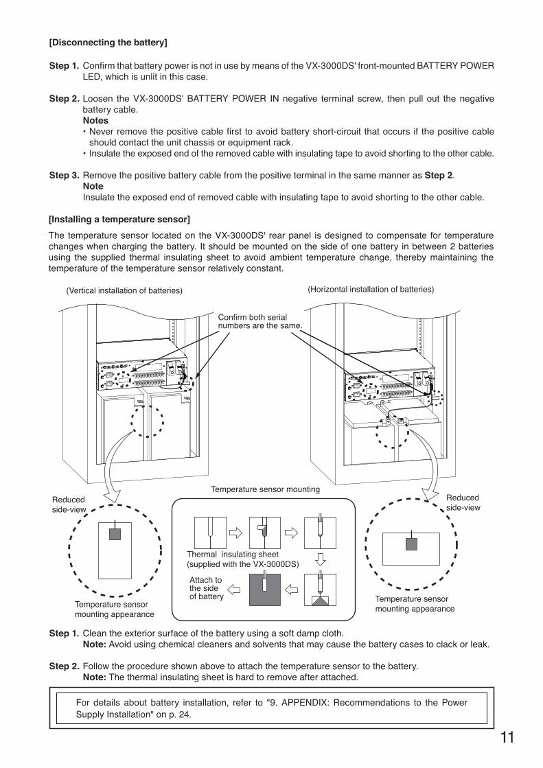
Step 1. ConfirmthatbatterypowerisnotinusebymeansoftheVX-3000DS'front-mountedBATTERYPOWERLED,whichisunlitinthiscase.
Step 2. Loosen theVX-3000DS'BATTERYPOWER INnegative terminal screw, thenpull out thenegativebattery cable.Notes•Neverremovethepositivecablefirst toavoidbatteryshort-circuit thatoccurs if thepositivecable
should contact the unit chassis or equipment rack.•Insulatetheexposedendoftheremovedcablewithinsulatingtapetoavoidshortingtotheothercable.
Step 3. Remove the positive battery cable from the positive terminal in the same manner as Step 2.NoteInsulatetheexposedendofremovedcablewithinsulatingtapetoavoidshortingtotheothercable.
[Disconnecting the battery]
[Installing a temperature sensor]The temperaturesensor locatedon theVX-3000DS' rearpanel isdesigned tocompensate for temperaturechanges when charging the battery. It should be mounted on the side of one battery in between 2 batteries using the supplied thermal insulating sheet to avoid ambient temperature change, thereby maintaining the temperature of the temperature sensor relatively constant.
For details about battery installation, refer to "9.APPENDIX:Recommendations to thePowerSupply Installation" on p. 24.
Reducedside-view
Reducedside-view
Thermal insulating sheet(supplied with the VX-3000DS)
Attach to the sideof battery
Temperature sensor mounting
Temperature sensormounting appearance
Temperature sensormounting appearance
Confirm both serial numbers are the same.
(Horizontal installation of batteries)(Vertical installation of batteries)
Step 1. Cleantheexteriorsurfaceofthebatteryusingasoftdampcloth.Note: Avoid using chemical cleaners and solvents that may cause the battery cases to clack or leak.
Step 2. Follow the procedure shown above to attach the temperature sensor to the battery.Note: The thermal insulating sheet is hard to remove after attached.
12
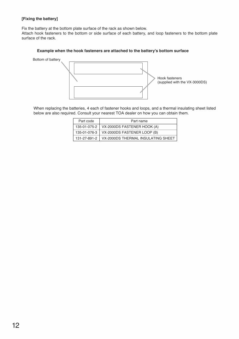
[Fixing the battery]
Fixthebatteryatthebottomplatesurfaceoftherackasshownbelow.Attach hook fasteners to the bottom or side surface of each battery, and loop fasteners to the bottom plate surface of the rack.
Hook fasteners(supplied with the VX-3000DS)
Bottom of battery
135-01-075-2135-01-076-3
VX-2000DS FASTENER HOOK (A)VX-2000DS FASTENER LOOP (B)
131-27-891-2 VX-2000DS THERMAL INSULATING SHEET
Part code Part name
When replacing the batteries, 4 each of fastener hooks and loops, and a thermal insulating sheet listed below are also required. Consult your nearest TOA dealer on how you can obtain them.
Example when the hook fasteners are attached to the battery's bottom surface
13
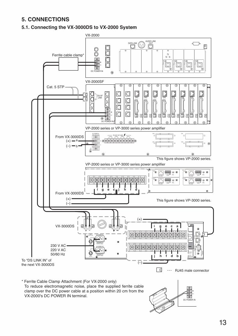
5. CONNECTIONS5.1. Connecting the VX-3000DS to VX-2000 System
DS-SFLINK
1
2
28 V 4.8 ADC POWER IN CH3 CH1
CH4 CH2
PA OUT (SP LINE)
C HCH1
C HCH2
C HCH3
C HCH4
DATA LINK
DC POWER IN
AUDIO LINK OUT
DC POWER IN
FUSE 35A (POWER OUT)BATTERY POWER IN24V MAX 150A
POWER OUT(-)
1234567POWER OUT(+) 19-33V MAX 25A
WARNINGTake special care to prevent the batteryfrom being shorted by misconnection
of the battery cable. If the shore occurs, the unit may fail.
OU
T
DS
LIN
K24
V(16
-25V
)M
AX 0
.3A
POW
ER O
UT
TEM
PER
ATU
RE
SEN
SOR
8
IN
(–)(+)
(–)(+)
RJ45 male connector
VX-2000SF
VX-2000
VP-2000 series or VP-3000 series power amplifier
VP-2000 series or VP-3000 series power amplifier
VX-3000DS
This figure shows VP-2000 series.
This figure shows VP-3000 series.
From VX-3000DS
From VX-3000DS
230 V AC220 V AC50/60 Hz
To “DS LINK IN” ofthe next VX-3000DS
a
Ferrite cable clamp*
i ag ce
j bh df
i g ce j h df
12
b
(–)
(+)
Cat. 5 STP
* Ferrite Cable Clamp Attachment (For VX-2000 only)To reduce electromagnetic noise, place the supplied ferrite cable clamp over the DC power cable at a position within 20 cm from the VX-2000'sDCPOWERINterminal.
DC POWER IN
14
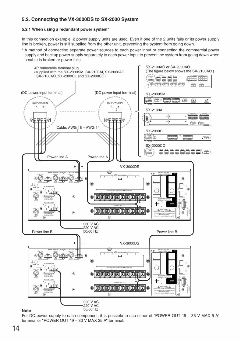
5.2. Connecting the VX-3000DS to SX-2000 System
5.2.1 when using a redundant power system*
Inthisconnectionexample,2powersupplyunitsareused.Evenifoneofthe2unitsfailsoritspowersupplyline is broken, power is still supplied from the other unit, preventing the system from going down.* A method of connecting separate power sources to each power input or connecting the commercial power
supply and backup power supply separately to each power input to prevent the system from going down when a cable is broken or power fails.
SX-2100AI
SX-2100AO or SX-2000AO(The figure below shows the SX-2100AO.)
Cable: AWG 18 – AWG 14
VX-3000DS
VX-3000DS
4P removable terminal plug (supplied with the SX-2000SM, SX-2100AI, SX-2000AO SX-2100AO, SX-2000CI, and SX-2000CO)
SX-2000SM
SX-2000CI
SX-2000CO
(DC power input terminal)
Power line BPower line B
Power line APower line A
(DC power input terminal)
230 V AC220 V AC50/60 Hz
230 V AC220 V AC50/60 Hz
+–
+–
TEM
PER
ATU
RE
SEN
SOR
24V(
16-2
5V)
POW
ER O
UT
MAX
0.3
A
INO
UT
DS
LIN
K
TEM
PER
ATU
RE
SEN
SOR
24V(
16-2
5V)
POW
ER O
UT
MAX
0.3
A
INO
UT
DS
LIN
K
+ -
+ -
NoteForDCpowersupplytoeachcomponent,it ispossibletouseeitherof"POWEROUT19–33VMAX5A"terminalor"POWEROUT19–33VMAX25A"terminal.
15
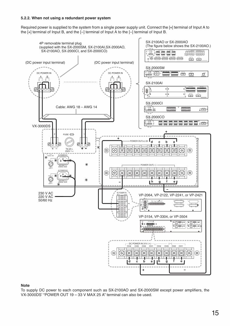
5.2.2. when not using a redundant power system
Requiredpowerissuppliedtothesystemfromasinglepowersupplyunit.Connectthe[+]terminalofInputAtothe[+]terminalofInputB,andthe[–]terminalofInputAtothe[–]terminalofInputB.
28 V 4.8 ADC POWER IN CH3 CH1
CH4 CH2
PA OUT (SP LINE)
C HCH1
C HCH2
C HCH3
C HCH4
28 V 4.8 ADC POWER IN
FUSE 35A (POWER OUT)BATTERY POWER IN24V MAX 150A
POWER OUT(-)
1234567POWER OUT(+) 19-33V MAX 25A
WARNINGTake special care to prevent the batteryfrom being shorted by misconnection
of the battery cable. If the shore occurs, the unit may fail.
OU
T
DS
LIN
K16
-24V
MAX
0.3
APO
WER
OU
T
TEM
PER
ATU
RE
SEN
SOR
8
IN
POWER OUT(-)
POWER OUT(+) 20
CH4 CH3 CH2 CH1 CH4 CH3 CH2 CH1
h g efd c ab
FUSE
250V
2 1
T6.3A L
d c ab
h g ef
VX-3000DS
4P removable terminal plug (supplied with the SX-2000SM, SX-2100AI,SX-2000AO, SX-2100AO, SX-2000CI, and SX-2000CO)
(DC power input terminal) (DC power input terminal)
SX-2100AI
SX-2100AO or SX-2000AO(The figure below shows the SX-2100AO.)
SX-2000SM
SX-2000CI
SX-2000CO
+
+
+
-
-
-
VP-2064, VP-2122, VP-2241, or VP-2421
VP-3154, VP-3304, or VP-3504
230 V AC220 V AC50/60 Hz
Cable: AWG 18 – AWG 14
NoteTosupplyDCpowertoeachcomponentsuchasSX-2100AOandSX-2000SMexceptpoweramplifiers,theVX-3000DS’“POWEROUT19–33VMAX25A”terminalcanalsobeused.
16
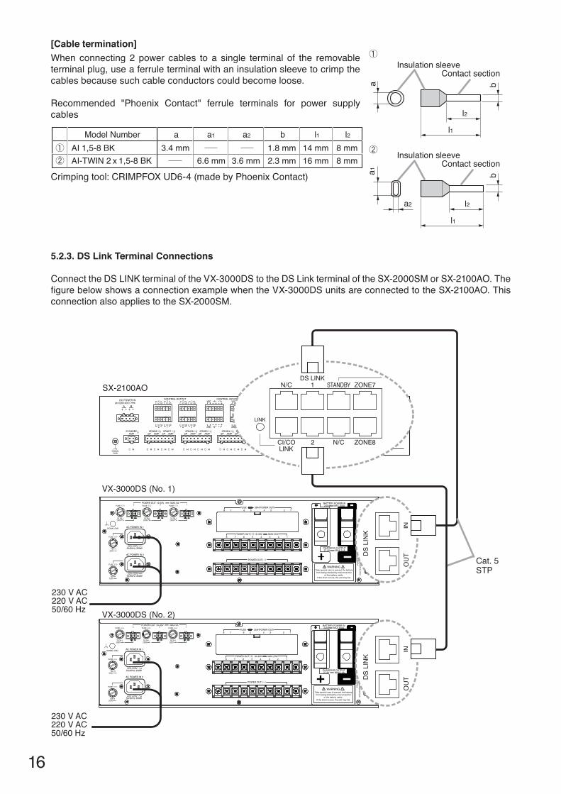
[Cable termination]Whenconnecting2power cables to a single terminal of the removableterminal plug, use a ferrule terminal with an insulation sleeve to crimp the cables because such cable conductors could become loose.
Recommended "Phoenix Contact" ferrule terminals for power supplycables
Crimpingtool:CRIMPFOXUD6-4(madebyPhoenixContact)
a
l2
a1
a2
l1
l2
l1
bb
Insulation sleeveContact section
Insulation sleeveContact section
5.2.3. DS link Terminal Connections
ConnecttheDSLINKterminaloftheVX-3000DStotheDSLinkterminaloftheSX-2000SMorSX-2100AO.ThefigurebelowshowsaconnectionexamplewhentheVX-3000DSunitsareconnectedtotheSX-2100AO.Thisconnection also applies to the SX-2000SM.
TEM
PER
ATU
RE
SEN
SOR
24V(
16-2
5V)
POW
ER O
UT
MAX
0.3
A
INO
UT
DS
LIN
K
TEM
PER
ATU
RE
SEN
SOR
24V(
16-2
5V)
POW
ER O
UT
MAX
0.3
A
INO
UT
DS
LIN
K
DS
LIN
K
INO
UT
DS
LIN
K
INO
UT
SX-2100AO
VX-3000DS (No. 1)
VX-3000DS (No. 2)
230 V AC220 V AC50/60 Hz
230 V AC220 V AC50/60 Hz
Cat. 5STP
Model Number a1 l1 l2AI 1,5-8 BKAI-TWIN 2 x 1,5-8 BK 6.6 mm
a2
3.6 mm14 mm16 mm2.3 mm
8 mm8 mm
a3.4 mm
b1.8 mm
17
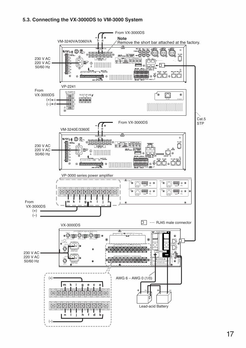
5.3. Connecting the VX-3000DS to Vm-3000 System
VX-3000DS
VP-2241
PA LINK VP-200VX
28 V 4.8 ADC POWER IN
PA OUT (SP LINE)C H
TEM
PER
ATU
RE
SEN
SOR
24V(
16-2
5V)
POW
ER O
UT
MAX
0.3
A
INO
UT
DS
LIN
K
RJ45 male connector
AWG 6 – AWG 0 (1/0)
VM-3240VA/3360VA
FromVX-3000DS
From VX-3000DS
From VX-3000DS
Note Remove the short bar attached at the factory.
230 V AC220 V AC50/60 Hz
230 V AC220 V AC50/60 Hz
230 V AC220 V AC50/60 Hz
Lead-acid Battery
(–)(+)
+
VP-3000 series power amplifier
VM-3240E/3360E
-
+-Cat.5STP
a
ef
cd
b
(–)(+)
From VX-3000DS
m k gi n l hj
ikm ag ce
jln bh df
(–)
(+)
18
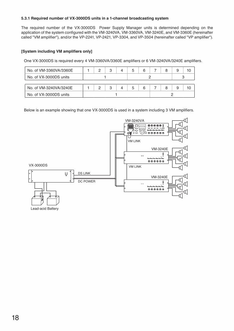
5.3.1 Required number of VX-3000DS units in a 1-channel broadcasting system
The required number of the VX-3000DS Power Supply Manager units is determined depending on the applicationofthesystemconfiguredwiththeVM-3240VA,VM-3360VA,VM-3240E,andVM-3360E(hereinaftercalled"VMamplifier"),and/ortheVP-2241,VP-2421,VP-3304,andVP-3504(hereinaftercalled"VPamplifier").
[System including Vm amplifiers only]
OneVX-3000DSisrequiredevery4VM-3360VA/3360Eamplifiersor6VM-3240VA/3240Eamplifiers.
BelowisanexampleshowingthatoneVX-3000DSisusedinasystemincluding3VMamplifiers.
No.ofVM-3360VA/3360E 1 2 3 4 5 6 7 8 9 10No.ofVX-3000DSunits 1 2 3
VM LINK
DC POWER
DS LINK
VM-3240VA
VM-3240E
VM-3240E
Lead-acid Battery
VX-3000DS VM LINK
No.ofVM-3240VA/3240E 1 2 3 4 5 6 7 8 9 10No.ofVX-3000DSunits 1 2
19
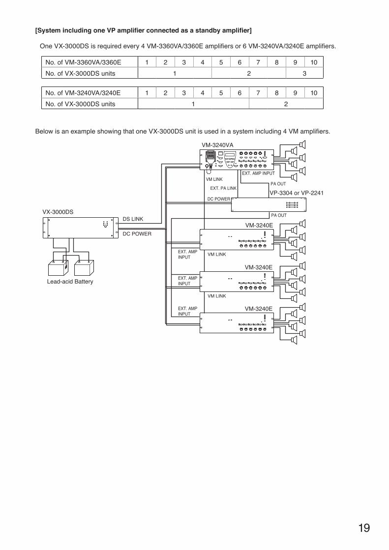
[System including one VP amplifier connected as a standby amplifier]
OneVX-3000DSisrequiredevery4VM-3360VA/3360Eamplifiersor6VM-3240VA/3240Eamplifiers.
BelowisanexampleshowingthatoneVX-3000DSunitisusedinasystemincluding4VMamplifiers.
VM-3240VA
VX-3000DS
VP-3304 or VP-2241
EXT. AMP INPUT
EXT. PA LINK
DC POWER
VM LINK
DC POWER
DS LINK
PA OUT
PA OUT
VM-3240E
VM-3240E
VM-3240E
EXT. AMP INPUT
EXT. AMP INPUT
VM LINK
VM LINK
EXT. AMP INPUTLead-acid Battery
No.ofVM-3360VA/3360E 1 2 3 4 5 6 7 8 9 10No.ofVX-3000DSunits 1 2 3
No.ofVM-3240VA/3240E 1 2 3 4 5 6 7 8 9 10No.ofVX-3000DSunits 1 2
20
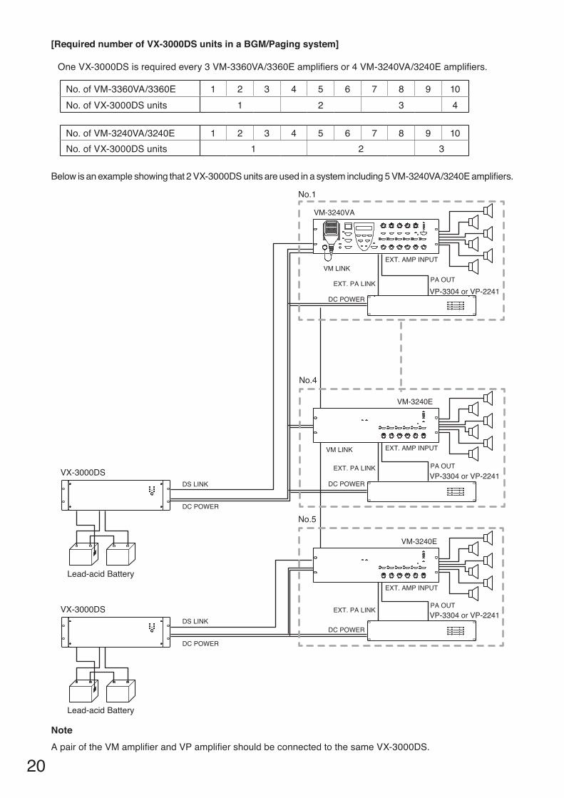
Belowisanexampleshowingthat2VX-3000DSunitsareusedinasystemincluding5VM-3240VA/3240Eamplifiers.
[Required number of VX-3000DS units in a BGm/Paging system]
OneVX-3000DSisrequiredevery3VM-3360VA/3360Eamplifiersor4VM-3240VA/3240Eamplifiers.
VM-3240E
VM-3240E
VM-3240VA
VP-3304 or VP-2241
VP-3304 or VP-2241
EXT. AMP INPUT
EXT. PA LINK
DC POWER
VM LINK
DC POWER
DS LINK
DC POWER
DS LINK
VM LINK
PA OUT
EXT. AMP INPUT
EXT. PA LINK PA OUT
EXT. AMP INPUT
EXT. PA LINK PA OUT
DC POWER
DC POWER
VP-3304 or VP-2241
VX-3000DS
VX-3000DS
No.4
No.1
Lead-acid Battery
Lead-acid Battery
No.5
NoteApairoftheVMamplifierandVPamplifiershouldbeconnectedtothesameVX-3000DS.
No.ofVM-3360VA/3360E 1 2 3 4 5 6 7 8 9 10No.ofVX-3000DSunits 1 2 3 4
No.ofVM-3240VA/3240E 1 2 3 4 5 6 7 8 9 10No.ofVX-3000DSunits 1 2 3
21
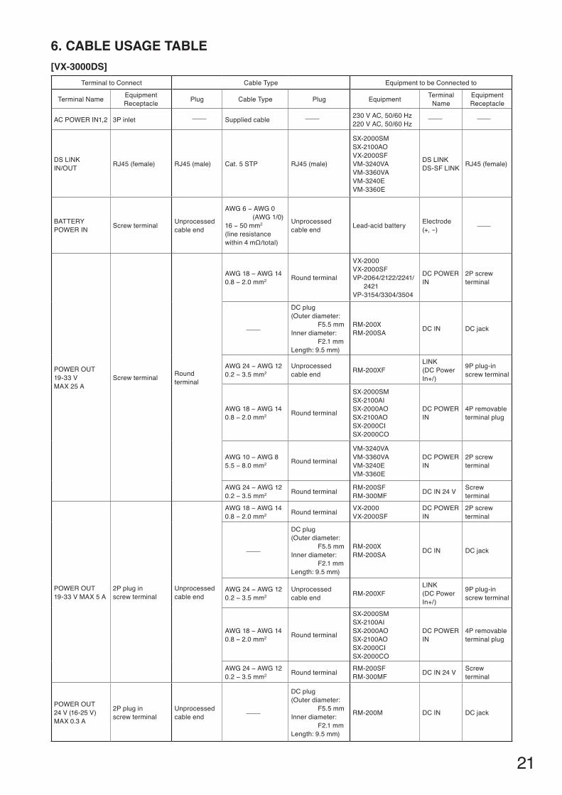
6. CABlE USAGE TABlE[VX-3000DS]
Terminal to Connect Cable Type Equipment to be Connected to
TerminalName Equipment Receptacle Plug Cable Type Plug Equipment Terminal
NameEquipment Receptacle
ACPOWERIN1,2 3P inlet Supplied cable 230VAC,50/60Hz220VAC,50/60Hz
DSLINKIN/OUT RJ45 (female) RJ45 (male) Cat. 5 STP RJ45 (male)
SX-2000SMSX-2100AOVX-2000SFVM-3240VAVM-3360VAVM-3240EVM-3360E
DSLINKDS-SFLINK RJ45 (female)
BATTERYPOWERIN Screw terminal Unprocessed
cable end
AWG6−AWG0(AWG1/0)16−50mm2
(line resistance within4mΩ/total)
Unprocessedcable end Lead-acidbattery Electrode
(+,-)
POWEROUT19-33 V MAX 25 A
Screw terminal Round terminal
AWG18−AWG140.8−2.0mm2 Round terminal
VX-2000VX-2000SFVP-2064/2122/2241/ 2421VP-3154/3304/3504
DCPOWERIN
2P screw terminal
DC plug(Outerdiameter: F5.5 mmInnerdiameter: F2.1 mmLength:9.5mm)
RM-200XRM-200SA DCIN DC jack
AWG24−AWG120.2−3.5mm2
Unprocessedcable end RM-200XF
LINK(DC Power In+/)
9P plug-in screw terminal
AWG18−AWG140.8−2.0mm2 Round terminal
SX-2000SMSX-2100AISX-2000AOSX-2100AOSX-2000CISX-2000CO
DCPOWERIN
4P removable terminal plug
AWG10−AWG85.5−8.0mm2 Round terminal
VM-3240VAVM-3360VAVM-3240EVM-3360E
DCPOWERIN
2P screw terminal
AWG24−AWG120.2−3.5mm2 Round terminal RM-200SF
RM-300MF DCIN24V Screw terminal
POWEROUT19-33 V MAX 5 A
2P plug inscrew terminal
Unprocessedcable end
AWG18−AWG140.8−2.0mm2 Round terminal VX-2000
VX-2000SFDCPOWERIN
2P screw terminal
DC plug(Outerdiameter: F5.5 mmInnerdiameter: F2.1 mmLength:9.5mm)
RM-200XRM-200SA DCIN DC jack
AWG24−AWG120.2−3.5mm2
Unprocessedcable end RM-200XF
LINK(DC Power In+/)
9P plug-in screw terminal
AWG18−AWG140.8−2.0mm2 Round terminal
SX-2000SMSX-2100AISX-2000AOSX-2100AOSX-2000CISX-2000CO
DCPOWERIN
4P removable terminal plug
AWG24−AWG120.2−3.5mm2 Round terminal RM-200SF
RM-300MF DCIN24V Screw terminal
POWEROUT24 V (16-25 V)MAX 0.3 A
2P plug inscrew terminal
Unprocessedcable end
DC plug(Outerdiameter: F5.5 mmInnerdiameter: F2.1 mmLength:9.5mm)
RM-200M DCIN DC jack
22
7. SwITCHING OFF SySTEm POwER (DC)
Connector Name
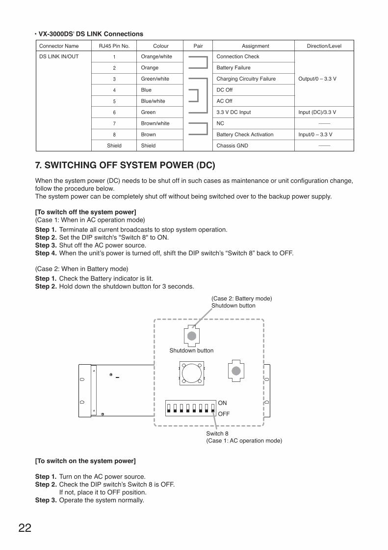
• VX-3000DS' DS LINK Connections
DS LINK IN/OUT
RJ45 Pin No.
Orange/white
Shield
Brown
Brown/white
Green
Blue/white
Blue
Green/white
Input/0 – 3.3 V
Input (DC)/3.3 V
Output/0 – 3.3 V
Orange
Connection Check
Chassis GND
Battery Check Activation
NC
3.3 V DC Input
AC Off
DC Off
Charging Circuitry Failure
Battery Failure
Colour Pair Assignment Direction/Level
Shield
1
2
3
4
5
6
7
8
Whenthesystempower(DC)needstobeshutoffinsuchcasesasmaintenanceorunitconfigurationchange,follow the procedure below.The system power can be completely shut off without being switched over to the backup power supply.
[To switch off the system power](Case1:WheninACoperationmode) Step 1. Terminate all current broadcasts to stop system operation. Step 2. SettheDIPswitch's"Switch8"toON. Step 3. Shut off the AC power source. Step 4. Whentheunit’spoweristurnedoff,shifttheDIPswitch’s“Switch8”backtoOFF.
(Case2:WheninBatterymode) Step 1. Check the Battery indicator is lit. Step 2. Hold down the shutdown button for 3 seconds.
[To switch on the system power]
Step 1. Turn on the AC power source. Step 2. Check the DIP switch’s Switch 8 is OFF.
If not, place it to OFF position. Step 3. Operate the system normally.
DIPSW SETTING
CHARGECURRENT
11A5.5A
BATTERY INTERNALRESISTANCE
Plesae seea lower part.
TERMINATETERMINATE
OFF
AC POWERIN2
NOT USEUSE
AC POWERLOSS
SHUTDOWNBATTERY MODE
FUNCTION
ONOFF
25mΩONON
4 50mΩOFF100mΩ
OFF
DISABLE
DS LINK1 2 3 4 5 6 7 8
5
Switch 8 (Case 1: AC operation mode)
ON
(Case 2: Battery mode) Shutdown button
Shutdown button
OFF
23
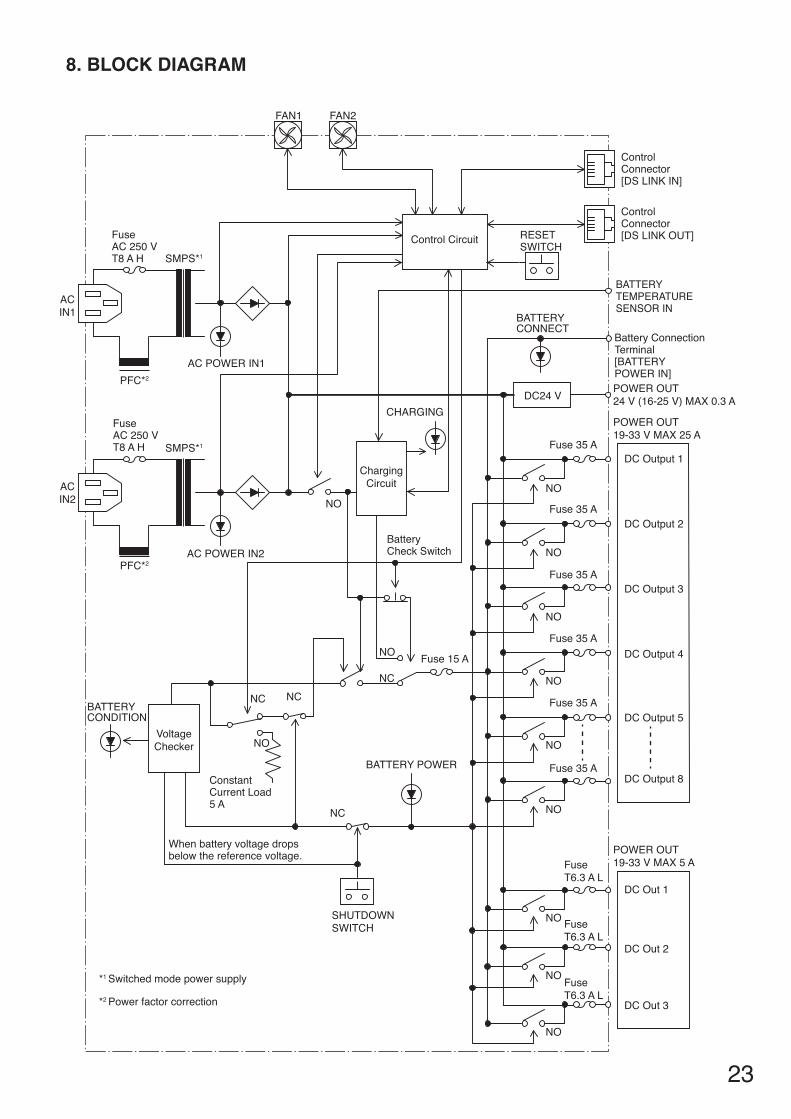
8. BlOCk DIAGRAm
Fuse T6.3 A L
Fuse T6.3 A L
Fuse T6.3 A L
DC Out 3
DC Out 2
DC Out 1
POWER OUT 19-33 V MAX 5 A
DC Output 3
DC Output 2
DC Output 1
POWER OUT 19-33 V MAX 25 A
POWER OUT 24 V (16-25 V) MAX 0.3 A
DC Output 8
DC Output 5
DC Output 4
DC24 V
Fuse 35 A
Fuse 35 A
Fuse 35 A
Fuse 35 A
Fuse 35 A
Fuse 35 A
Control Circuit
ChargingCircuit
CHARGING
Fuse 15 ANO
VoltageChecker
BATTERYCONDITION
BATTERY POWER
NC
NC NCNC
NO
BatteryCheck Switch
When battery voltage dropsbelow the reference voltage.
ACIN1
ACIN2
ControlConnector[DS LINK IN]
Control Connector[DS LINK OUT]
FAN2FAN1
AC POWER IN1
AC POWER IN2
FuseAC 250 VT8 A H
FuseAC 250 VT8 A H
NO
NO
NO
NO
NO
NO
Constant Current Load5 A
NO
BATTERY TEMPERATURESENSOR IN
Battery ConnectionTerminal [BATTERY POWER IN]
BATTERYCONNECT
SHUTDOWNSWITCH
RESETSWITCH
SMPS*1
SMPS*1
PFC*2
PFC*2
*1 Switched mode power supply
*2 Power factor correction
NO
NO
NO
24
9. APPENDIX: Recommendations to the Power Supply Installation
Incorrect installations of the power supply manager VX-3000DS and its related equipment as batteries can cause unnecessary fault indications. This information sheet gives you helpful hints and recommendations to avoid it.
Please also take care on the battery handling hints.
BatteryStorage
The recommended storage conditions (duration, temperature) of charged and uncharged batteries must not be exceededtoavoidatotaldischargethatdestroysthebattery.Considerthestoragetimeslistedbelow:
1. storage in factory, distributor, dealer and own company 2. in the project, when the VA system is installed but not in use, respective not powered, so that the
batteries will not be trickle charged´
The storage and discharge duration depend on the ambient temperatures and can be found in the battery data sheets.Themaximumstoragedurationsare:
Ambient temperature Maximumtimebeforere-chargeLessthan20°C 12 months20°C–30°C 9 months20°C–40°C 6 months
The production date is usually printed on the battery. In case you do not know the storage conditions of the dealer or distributor, then it is preferable consider the worst case.
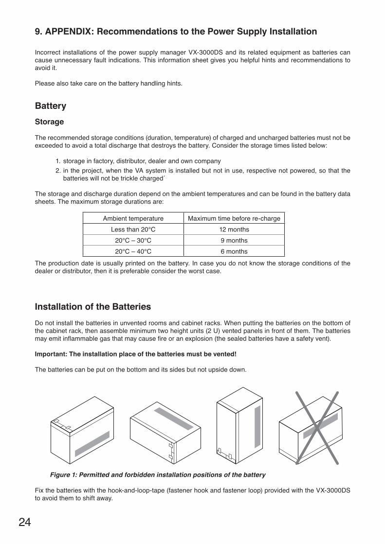
Installation of the BatteriesDonotinstallthebatteriesinunventedroomsandcabinetracks.Whenputtingthebatteriesonthebottomofthecabinetrack,thenassembleminimumtwoheightunits(2U)ventedpanelsinfrontofthem.Thebatteriesmayemitinflammablegasthatmaycausefireoranexplosion(thesealedbatterieshaveasafetyvent).
Important: The installation place of the batteries must be vented!
The batteries can be put on the bottom and its sides but not upside down.
Fixthebatterieswiththehook-and-loop-tape(fastenerhookandfastenerloop)providedwiththeVX-3000DSto avoid them to shift away.
Figure 1: Permitted and forbidden installation positions of the battery
25
Battery Connection
Clean Contacts
Take care that the connection terminals are clean before connecting the cables. Clean them if necessary.
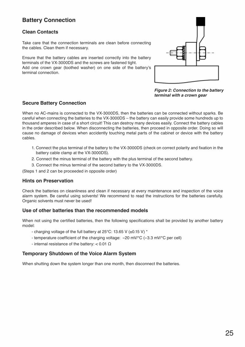
Ensure that the battery cables are inserted correctly into the battery terminals of the VX-3000DS and the screws are fastened tight.Add one crown gear (toothed washer) on one side of the battery’s terminal connection.
Secure Battery Connection
WhennoAC-mainsisconnectedtotheVX-3000DS,thenthebatteriescanbeconnectedwithoutsparks.BecarefulwhenconnectingthebatteriestotheVX-3000DS–thebatterycaneasilyprovidesomehundredsuptothousand amperes in case of a short circuit! This can destroy many devices easily. Connect the battery cables intheorderdescribedbelow.Whendisconnectingthebatteries,thenproceedinoppositeorder.Doingsowillcause no damage of devices when accidently touching metal parts of the cabinet or device with the battery cables.
1.ConnecttheplusterminalofthebatterytotheVX-3000DS(checkoncorrectpolarityandfixationinthebattery cable clamp at the VX-3000DS).
2. Connect the minus terminal of the battery with the plus terminal of the second battery.3. Connect the minus terminal of the second battery to the VX-3000DS.
(Steps 1 and 2 can be proceeded in opposite order)
Hints on Preservation
Check the batteries on cleanliness and clean if necessary at every maintenance and inspection of the voice alarmsystem.Becarefulusingsolvents!Werecommendtoreadthe instructionsfor thebatteriescarefully.Organic solvents must never be used!
Use of other batteries than the recommended models
Whennotusingthecertifiedbatteries,thenthefollowingspecificationsshallbeprovidedbyanotherbatterymodel:
-chargingvoltageofthefullbatteryat25°C:13.65V(±0.15V)*-temperaturecoefficientofthechargingvoltage: -20mV/°C(-3.3mV/°Cpercell)-internalresistanceofthebattery:<0.01Ω
Temporary Shutdown of the Voice Alarm System
Whenshuttingdownthesystemlongerthanonemonth,thendisconnectthebatteries.
Figure 2: Connection to the battery terminal with a crown gear
26
VX-3000DS
The power manager VX-3000DS monitors the availability of the AC power and switches on the battery in case of a total loss of that power.
WhentheACpowerisavailable,thenthebatterieswillbecharged.Thechargecurrentismonitored,andwhenitisbelow2mA,thenachargerfaultwillbeenteredintothelogfileofthesystem.Theindications“BATTERYCONNECT“and“CHARGING“donotlight.
The battery surveillance of the VX-3000DS measures the resistance of the battery circuit at the set intervals. A battery fault will be logged when this resistance is higher than the initial value set by the DIP switch (p. 6). Theindication“BATTERYCONDITION“extinguishes.Thebatterytestcanbeproceededbypushingthebutton“BATTERYCHECK“.
The VX-3000DS should be installed at a low position in the cabinet rack.
Temperature SensorPurpose and CharacteristicsThe temperature sensor measures the ambient temperature of the battery to control the charging voltage. Whenthevoltageistoohigh,thenthebatterycanproducegasthatcancausethebatterytobreak.Thegascanleakthroughthepressurecontrolvalveanddevelopanexplosivegas,thereforethecabinetrackandtheroommustbevented.Thebatterycannotbechargedfullywhenthechargingvoltageistoolow.Whenthecurrentintothebatteryislessthan2mA,thenachargererrorwillbeloggedandthe“Charge”LEDextinguishes.
The temperature sensor must not be disconnected during charging of the battery because then the charging voltagebecomeshighcausingthedangeroussituationsexplainedabove.Whenexchangingthetemperaturesensor, the charging voltage of the VX-3000DS must be re-adjusted by TOA dealer.
Installation
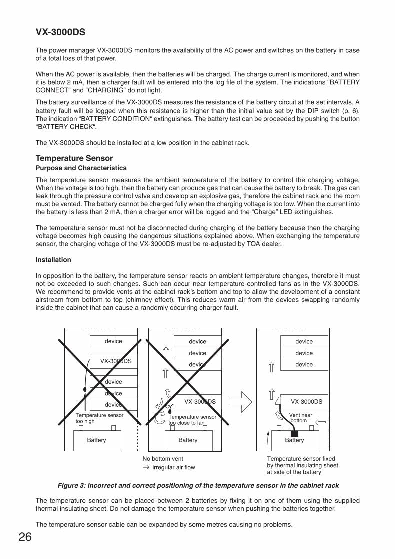
In opposition to the battery, the temperature sensor reacts on ambient temperature changes, therefore it must notbeexceededtosuchchanges.Suchcanoccurneartemperature-controlledfansas intheVX-3000DS.Werecommendtoprovideventsatthecabinetrack’sbottomandtoptoallowthedevelopmentofaconstantairstream from bottom to top (chimney effect). This reduces warm air from the devices swapping randomly inside the cabinet that can cause a randomly occurring charger fault.
device
device
deviceTemperature sensortoo high
device
Battery
VX-3000DS
No bottom vent irregular air flow
Temperature sensor fixed by thermal insulating sheet at side of the battery
Temperature sensortoo close to fan
device
device
device
Battery
VX-3000DS
Vent near bottom
device
device
device
Battery
VX-3000DS
Figure 3: Incorrect and correct positioning of the temperature sensor in the cabinet rack
The temperaturesensor canbeplacedbetween2batteriesbyfixing it ononeof themusing thesuppliedthermal insulating sheet. Do not damage the temperature sensor when pushing the batteries together.
Thetemperaturesensorcablecanbeexpandedbysomemetrescausingnoproblems.
27
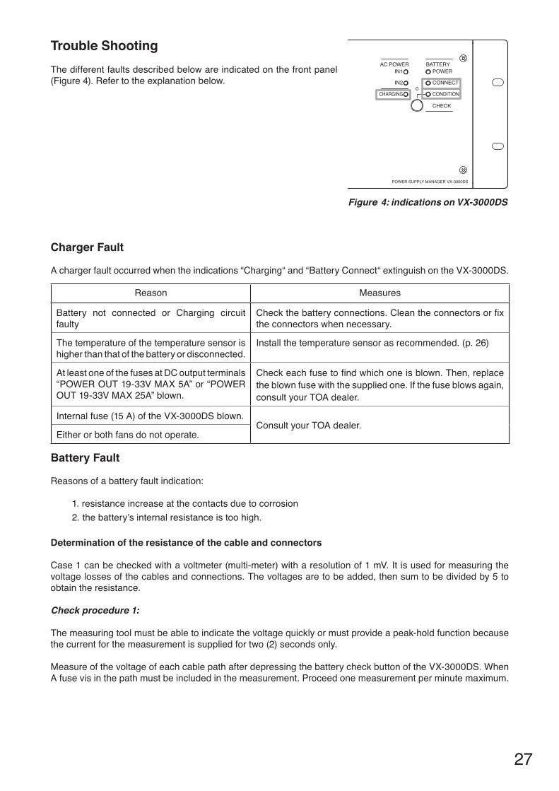
Trouble ShootingThe different faults described below are indicated on the front panel (Figure4).Refertotheexplanationbelow.
AC POWER BATTERYIN1
IN2
POWER
CONNECT
CONDITION
POWER SUPPLY MANAGER VX-3000DS
CHECK
CHARGING
Figure 4: indications on VX-3000DS
Charger Fault
Achargerfaultoccurredwhentheindications“Charging“and“BatteryConnect“extinguishontheVX-3000DS.
Reason Measures
Battery not connected or Charging circuit faulty
Checkthebatteryconnections.Cleantheconnectorsorfixthe connectors when necessary.
The temperature of the temperature sensor is higher than that of the battery or disconnected.
Install the temperature sensor as recommended. (p. 26)
At least one of the fuses at DC output terminals “POWEROUT19-33VMAX5A”or“POWEROUT19-33VMAX25A”blown.
Checkeachfusetofindwhichoneisblown.Then,replacethe blown fuse with the supplied one. If the fuse blows again, consult your TOA dealer.
Internal fuse (15 A) of the VX-3000DS blown.Consult your TOA dealer.
Either or both fans do not operate.
Battery Fault
Reasonsofabatteryfaultindication:
1. resistance increase at the contacts due to corrosion 2. the battery’s internal resistance is too high.
Determination of the resistance of the cable and connectors
Case 1 can be checked with a voltmeter (multi-meter) with a resolution of 1 mV. It is used for measuring the voltage losses of the cables and connections. The voltages are to be added, then sum to be divided by 5 to obtain the resistance.
Check procedure 1:
The measuring tool must be able to indicate the voltage quickly or must provide a peak-hold function because the current for the measurement is supplied for two (2) seconds only.
MeasureofthevoltageofeachcablepathafterdepressingthebatterycheckbuttonoftheVX-3000DS.WhenAfusevisinthepathmustbeincludedinthemeasurement.Proceedonemeasurementperminutemaximum.
28
Check procedure 2:
This measurement can be done with a slow voltmeter.
DisconnecttheVAunit’spowersupplyfromtheDCoutputfromtheVX-3000DSandconnectaloadof5-6Ω/600WtotheDCoutput(whenthecurrentoftheconnectedsystemcomponentsisknown),thentakecarethatthetotalcurrentisapproximately5A.Donotmeasureatoolongtimetoavoidreducingthebattery’scapacitytoo much.
Measure the voltage of each cable path while the load is connected.
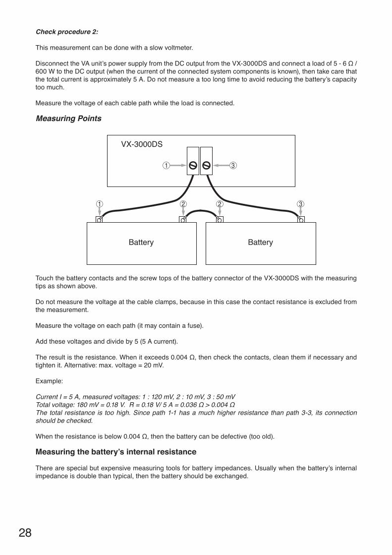
measuring Points
Touch the battery contacts and the screw tops of the battery connector of the VX-3000DS with the measuring tips as shown above.
Donotmeasurethevoltageatthecableclamps,becauseinthiscasethecontactresistanceisexcludedfromthe measurement.
Measure the voltage on each path (it may contain a fuse).
Add these voltages and divide by 5 (5 A current).
Theresultistheresistance.Whenitexceeds0.004Ω,thencheckthecontacts,cleanthemifnecessaryandtightenit.Alternative:max.voltage=20mV.
Example:
CurrentI=5A,measuredvoltages:1:120mV,2:10mV,3:50mVTotalvoltage:180mV=0.18V.R=0.18V/5A=0.036Ω>0.004ΩThe total resistance is too high. Since path 1-1 has a much higher resistance than path 3-3, its connection should be checked.
Whentheresistanceisbelow0.004Ω,thenthebatterycanbedefective(tooold).
measuring the battery’s internal resistance
Therearespecialbutexpensivemeasuringtoolsforbatteryimpedances.Usuallywhenthebattery’sinternalimpedanceisdoublethantypical,thenthebatteryshouldbeexchanged.
1
2 2
3
31
Battery
VX-3000DS
Battery
29
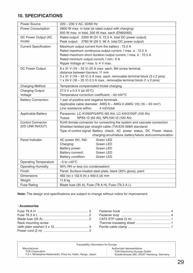
Power Source 220–230VAC,50/60HzPower Consumption 2800Wmax.intotal(atratedoutputwithcharging)
650Wmax.intotal,350Wmax.each(EN60065)DC Power Output (AC mode)
Ratedoutput:2300W(31V,72.5A,totalDCpoweroutput)Peakoutput: 2780W(29V,96A,totalDCpoweroutput)
CurrentSpecification Maximumoutputcurrentfromthebattery:72.5ARatedmaximumcontinuousoutputcurrent,Imax.a:72.5ARatedmaximumshortdurationoutputcurrent,Imax.b:72.5ARatedminimumoutputcurrent,Imin.:0ARippleVoltageatImax.b:4Vmax.
DC Power Output 8x31V(19–33V)25Amax.each,M4screwterminal,distancebetweenbarriers:11mm3x31V(19–33V)5Amax.each,removableterminalblock(3x2pins)1x24V(16–25V)0.3Amax.,removableterminalblock(1x2pins)
Charging Method Temperature compensated trickle chargingCharging Output Voltage
27.3V±0.3V(at25°C)Temperaturecorrectioncoefficient:–40mV/°C
Battery Connection 1 pair of positive and negative terminalsApplicablecablediameter:AWG6−AWG0(AWG1/0)(16–50mm2)Lineresistancewithin: 4mΩ/total
Applicable Battery Panasonic:LC-X1265PG/APG(65Ah),LC-XA12100P(100Ah)Yuasa: NP65-12(65Ah),NPL100-12(100Ah)
Control Connector(DSLINKIN/OUT)
RJ45 female connector for connecting the system and cascade connectionShieldedtwisted-pairstraightcable(TIA/EIA-568Astandard)Typeofcontrolsignal:Battery check, AC power status, DC Power status,
charging circuit failure, battery failure, and communicationPanel Indicator ACpowerIN1,IN2: GreenLED
Charging: GreenLEDBatterypower: GreenLEDBatteryconnect: GreenLEDBatterycondition: GreenLED
Operating Temperature –5to+45°COperating Humidity 90% RH or less (no condensation)Finish Panel:Surface-treatedsteelplate,black(30%gloss),paintDimensions 482(w)x132.6(h)x400.5(d)mmWeight 11.8 kgFuse Rating Bladefuse(35A),Fuse(T8AH),Fuse(T6.3AL)
Fuse T8 A H ......................................................... 2FuseT6.3AL ....................................................... 2Blade fuse (35 A) ................................................... 2 Rack mounting screw (withplainwasher)5x12 ...................................... 4Power cord (2 m) .................................................. 2
Fastener hook ...................................................... 4Fastener loop ....................................................... 4CAT5 STP cable (3 m) .......................................... 1Thermal insulating sheet ...................................... 1Ferrite cable clamp ............................................... 1
Note: Thedesignandspecificationsaresubjecttochangewithoutnoticeforimprovement.
10. SPECIFICATIONS
• Accessories
Traceability Information for EuropeManufacturer:
TOA Corporation7-2-1,Minatojima-Nakamachi,Chuo-ku,Kobe,Hyogo,Japan
Authorizedrepresentative:TOAElectronicsEuropeGmbHSuederstrasse282,20537Hamburg,Germany
URL:http://www.toa.jp/133-22-402-50