Embed Size (px)
Citation preview
USA401 York AvenueDuryea, PA 18642
Canada5096 South Service RoadBeamsville, Ontario L0R 1B3
UK32 Wedgwood RoadBicester, Oxfordshire OX26 4ULwww.quantumrehab.co.uk
Australia20-24 Apollo DriveHallam, Victoria 3803www.quantumrehab.com.au
New Zealand38 Lansford CrescentAvondaleAuckland, New Zealand 1007www.pridemobility.co.nz
ItalyVia del Progresso, ang. Via del LavoroLoc. Prato della Corte00065 Fiano Romano (RM)www.quantumrehab-italia.it
B.V.Castricummer Werf 261901 RW CastricumThe Netherlandswww.quantumrehab.eu
www.quantumrehab.com
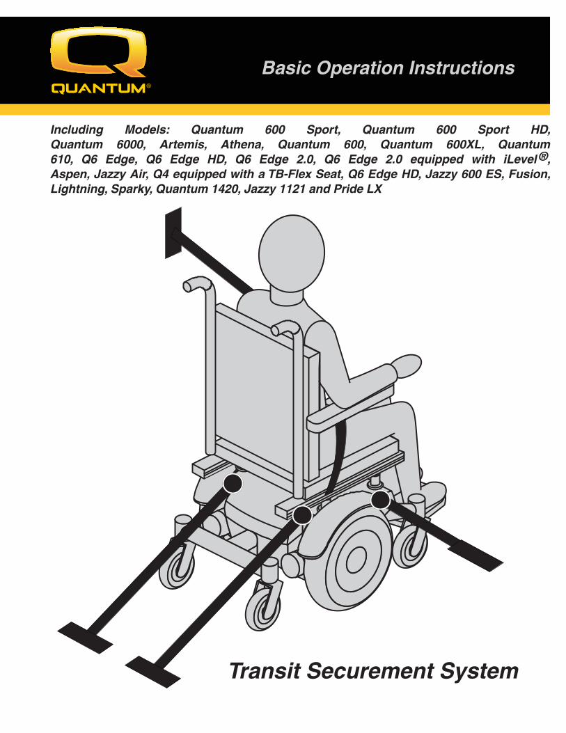
Basic Operation Instructions
Transit Securement System
Including Models: Quantum 600 Sport, Quantum 600 Sport HD, Quantum 6000, Artemis, Athena, Quantum 600, Quantum 600XL, Quantum 610, Q6 Edge, Q6 Edge HD, Q6 Edge 2.0, Q6 Edge 2.0 equipped with iLevel ®, Aspen, Jazzy Air, Q4 equipped with a TB-Flex Seat, Q6 Edge HD, Jazzy 600 ES, Fusion, Lightning, Sparky, Quantum 1420, Jazzy 1121 and Pride LX
54 Contents
Copyright 2016INFMANU3661/Rev I/October 2016
Introduction .........................................................................................................................................3
Label Information ...............................................................................................................................4
Defi nitions ............................................................................................................................................4
User Safety Information ......................................................................................................................5
Protocols and Procedures ...................................................................................................................5
Securing the Power Chair ....................................................................................................................6
Occupied Transit.....................................................................................................................................12
Transit Securement System ..............................................................................................................16
Important Points to Remember .........................................................................................................16
Appendix: Declarations .....................................................................................................................17
3Introduction
MANDATORY! The following information pertains to power chairs equipped with a factory-installed Pride Transit Securement Package. Read this information in its entirety before use in a motor vehicle. If you have any questions about this information or about using your power chair as a seat in a motor vehicle, contact your authorised Pride Dealer/Quantum Dealer.
The Pride Transit Securement Package conforms with the standard of ISO 7176-19 for the purpose of enabling power chairs to be secured in certain types of motor vehicles. The Transit Securement Package, including manufacturer-installed front and rear securement brackets, has been crash tested in accordance with ISO 7176-19, Frontal Impact Test, with a 76.2-kg (168-lb.) surrogate occupant corresponding to a user weight range of 52.16–95.25 kg (115–210 lbs.).
Notwithstanding this standard and testing conformance, many government transportation agencies, at the time of publication, have not approved any securement system of an occupied power chair in a motor vehicle. Therefore, it is the position of Pride Mobility Products that the Transit Securement Package should only be utilised to secure an occupied power chair being transported in a motor vehicle at the user’s discretion and in accordance with ISO 7176-19 standards, which are intended to increase safety, but do not suggest that compliance with the standards will necessarily prevent serious injury or death of a secured power chair occupant during motor vehicle transport.
In accordance with ISO 7176-19 standards, the power chair user should transfer into the vehicle seat and use the vehicle-installed belt restraint system if and whenever feasible. The Transit Securement Package is only available when factory-installed on new power chairs, and cannot be retrofi tted on existing power chairs or serviced in the fi eld.
PROHIBITED! Do not modify your power chair in any way not authorised by Pride/Quantum. Do not make alterations or substitutions to power chair structural parts or frame components without consulting Pride/Quantum.
4
Defi nintions ISO: International Standards Organization Transit Securement Package: Equipment installed on the power chair which allows the power
chair to be anchored in a motor vehicle. The equipment consists of tie-down anchor points and may include a pelvic belt.
Wheelchair Tie-down and Occupant Restraint System (WTORS): Equipment installed in a motor vehicle which allows a power chair and/or a power chair-seated occupant to be anchored in the motor vehicle for limiting occupant movement in a motor vehicle crash. The equipment consists of a system or device for securing the power chair and a belt-type restraint system.
Securement Points: Specifi c structural points on the power chair base or seat frame that are designed for attachment of a WTORS. These securement points are indicated by anchor symbols.
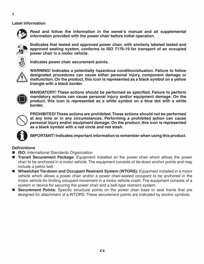
Label Information
Read and follow the information in the owner’s manual and all supplemental information provided with the power chair before initial operation.
IIndicates that tested and approved power chair, with similarly labeled tested and approved seating system, conforms to ISO 7176-19 for transport of an occupied power chair in a motor vehicle.
Indicates power chair securement points.
WARNING! Indicates a potentially hazardous condition/situation. Failure to follow designated procedures can cause either personal injury, component damage or malfunction. On the product, this icon is represented as a black symbol on a yellow triangle with a black border.
MANDATORY! These actions should be performed as specifi ed. Failure to perform mandatory actions can cause personal injury and/or equipment damage. On the product, this icon is represented as a white symbol on a blue dot with a white border.
PROHIBITED! These actions are prohibited. These actions should not be performed at any time or in any circumstances. Performing a prohibited action can cause personal injury and/or equipment damage. On the product, this icon is represented as a black symbol with a red circle and red slash.
IMPORTANT! Indicates important information to remember when using this product.
5
User Safety Information
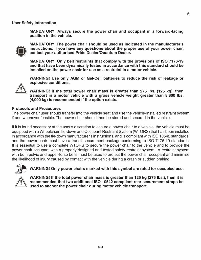
MANDATORY! Always secure the power chair and occupant in a forward-facing position in the vehicle.
MANDATORY! The power chair should be used as indicated in the manufacturer’s instructions. If you have any questions about the proper use of your power chair, contact your authorised Pride Dealer/Quantum Dealer.
MANDATORY! Only belt restraints that comply with the provisions of ISO 7176-19 and that have been dynamically tested in accordance with this standard should be installed on the power chair for use as a restraint in a motor vehicle.
WARNING! Use only AGM or Gel-Cell batteries to reduce the risk of leakage or explosive conditions.
WARNING! If the total power chair mass is greater than 275 lbs. (125 kg), then transport in a motor vehicle with a gross vehicle weight greater than 8,800 lbs. (4,000 kg) is recommended if the option exists.
Protocols and ProceduresThe power chair user should transfer into the vehicle seat and use the vehicle-installed restraint system if and whenever feasible. The power chair should then be stored and secured in the vehicle.
If it is found necessary at the user’s discretion to secure a power chair to a vehicle, the vehicle must be equipped with a Wheelchair Tie-down and Occupant Restraint System (WTORS) that has been installed in accordance with the tie-down manufacturer’s instructions, and is compliant with ISO 10542 standards, and the power chair must have a transit securement package conforming to ISO 7176-19 standards. It is essential to use a complete WTORS to secure the power chair to the vehicle and to provide the power chair occupant with a properly designed and tested safety restraint system. A restraint system with both pelvic and upper-torso belts must be used to protect the power chair occupant and minimise the likelihood of injury caused by contact with the vehicle during a crash or sudden braking.
WARNING! Only power chairs marked with this symbol are rated for occupied use.
WARNING! If the total power chair mass is greater than 125 kg (275 lbs.), then it is recommended that two additional ISO 10542 compliant rear securement straps be used to anchor the power chair during motor vehicle transport.
6
Securing the Power Chair
NOTE: In addition to following the general guidelines below, be sure to follow all recommendations and instructions provided by the WTORS manufacturer.
Always secure the power chair in a forward-facing position in the vehicle. Attach the four, six, or eight tie-down straps only to designated, labeled transit securement points
indicated by anchor symbols on the power chair. See fi gures 3 through 12. Tighten the straps to suffi ciently remove all slack.
Never attach tie-downs to adjustable, moving, or removable parts of the power chair such as armrests, front riggings and wheels.
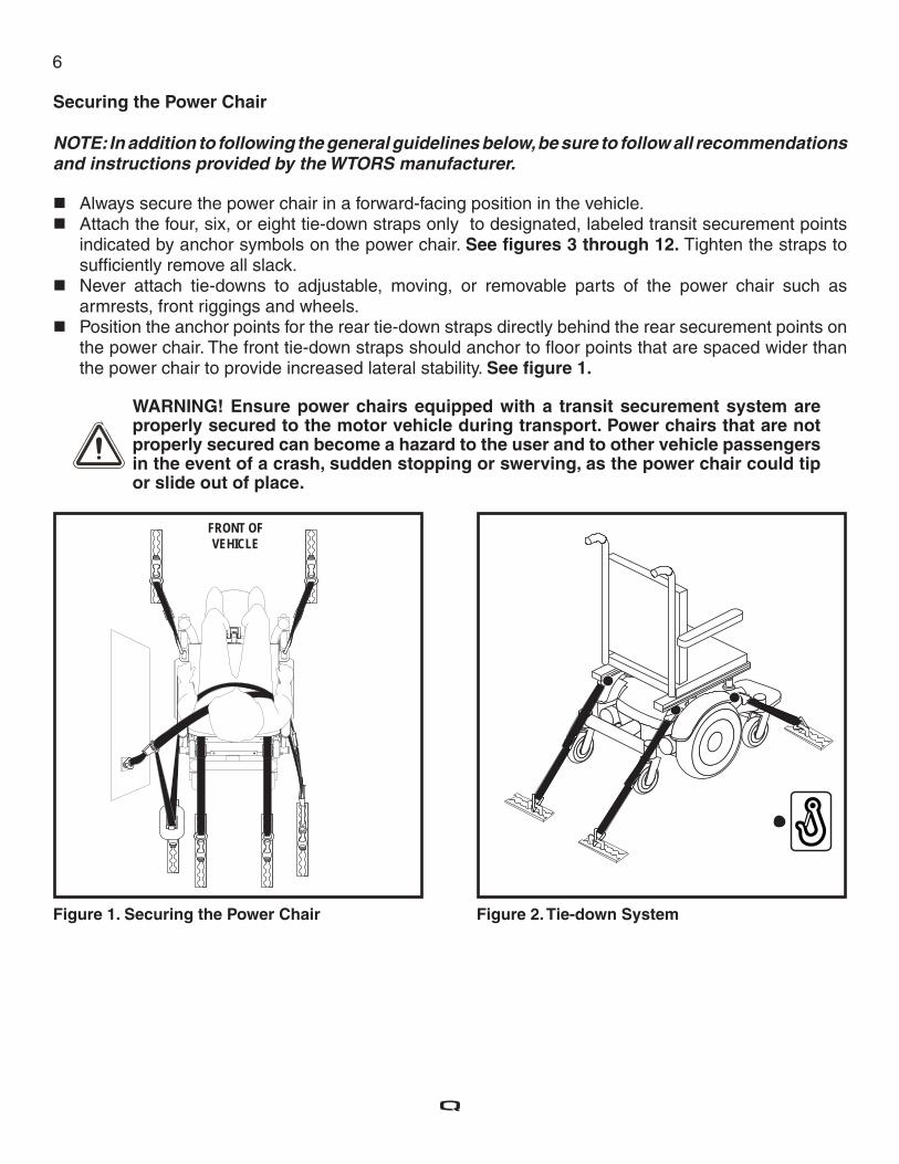
Position the anchor points for the rear tie-down straps directly behind the rear securement points on the power chair. The front tie-down straps should anchor to fl oor points that are spaced wider than the power chair to provide increased lateral stability. See fi gure 1.
WARNING! Ensure power chairs equipped with a transit securement system are properly secured to the motor vehicle during transport. Power chairs that are not properly secured can become a hazard to the user and to other vehicle passengers in the event of a crash, sudden stopping or swerving, as the power chair could tip or slide out of place.
FRONT OF VEHICLE
Figure 1. Securing the Power Chair Figure 2. Tie-down System
7
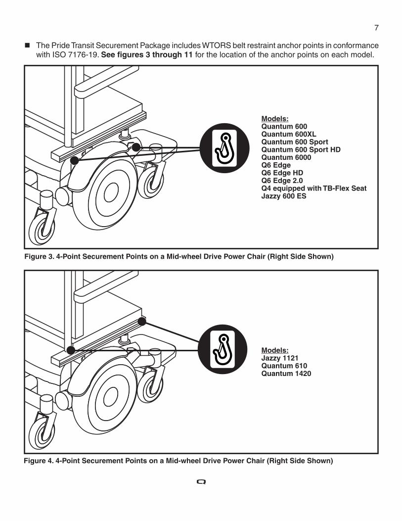
The Pride Transit Securement Package includes WTORS belt restraint anchor points in conformance with ISO 7176-19. See fi gures 3 through 11 for the location of the anchor points on each model.
Figure 4. 4-Point Securement Points on a Mid-wheel Drive Power Chair (Right Side Shown)
Figure 3. 4-Point Securement Points on a Mid-wheel Drive Power Chair (Right Side Shown)
Models: Quantum 600Quantum 600XLQuantum 600 SportQuantum 600 Sport HDQuantum 6000Q6 EdgeQ6 Edge HDQ6 Edge 2.0Q4 equipped with TB-Flex SeatJazzy 600 ES
Models: Jazzy 1121Quantum 610 Quantum 1420
8
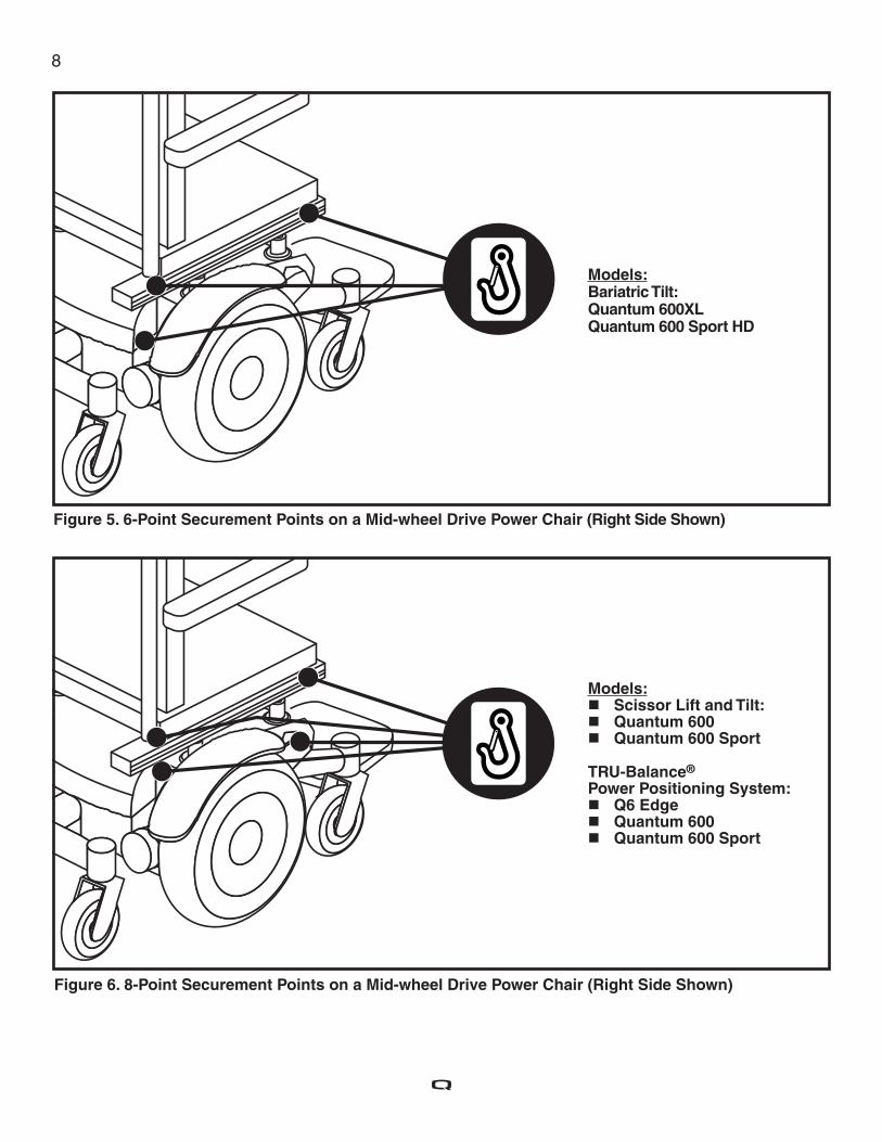
Figure 6. 8-Point Securement Points on a Mid-wheel Drive Power Chair (Right Side Shown)
Figure 5. 6-Point Securement Points on a Mid-wheel Drive Power Chair (Right Side Shown)
Models: Bariatric Tilt: Quantum 600XLQuantum 600 Sport HD
Models: Scissor Lift and Tilt: Quantum 600 Quantum 600 Sport
TRU-Balance® Power Positioning System:
Q6 Edge Quantum 600 Quantum 600 Sport
9
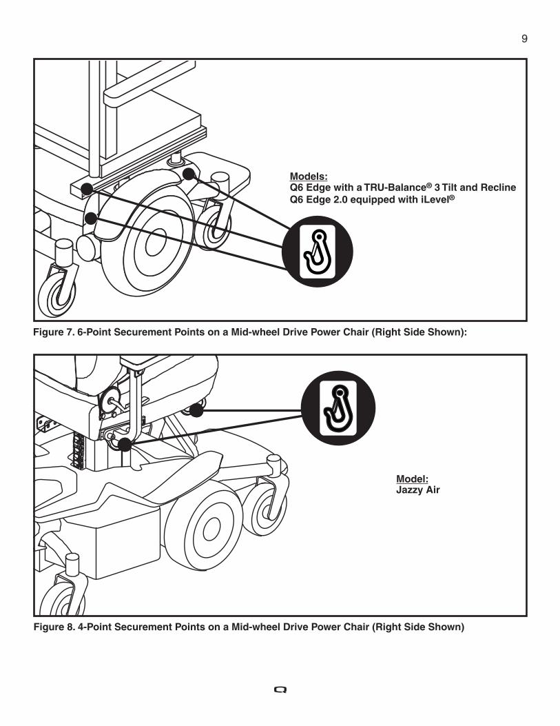
Figure 8. 4-Point Securement Points on a Mid-wheel Drive Power Chair (Right Side Shown)
Figure 7. 6-Point Securement Points on a Mid-wheel Drive Power Chair (Right Side Shown):
Models: Q6 Edge with a TRU-Balance® 3 Tilt and ReclineQ6 Edge 2.0 equipped with iLevel®
Model: Jazzy Air
10
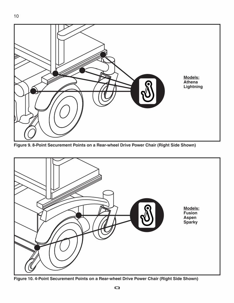
Figure 9. 8-Point Securement Points on a Rear-wheel Drive Power Chair (Right Side Shown)
Figure 10. 4-Point Securement Points on a Rear-wheel Drive Power Chair (Right Side Shown)
Models: AthenaLightning
Models: FusionAspen Sparky
11
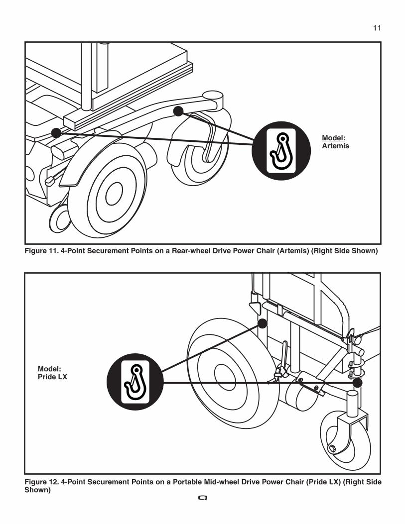
Figure 11. 4-Point Securement Points on a Rear-wheel Drive Power Chair (Artemis) (Right Side Shown)
Figure 12. 4-Point Securement Points on a Portable Mid-wheel Drive Power Chair (Pride LX) (Right Side Shown)
Model: Artemis
Model: Pride LX
12
Occupied TransitSecuring the Power Chair Occupant (Applies Only to Transit Systems Rated for Occupied Use) Once the power chair has been properly secured, it is essential that the power chair occupant be protected for transport.
WARNING! The power chair occupant must be secured with dynamically crash-tested and approved pelvic and upper-torso belts or with a fi ve-point child restraint harness as part of WTORS.
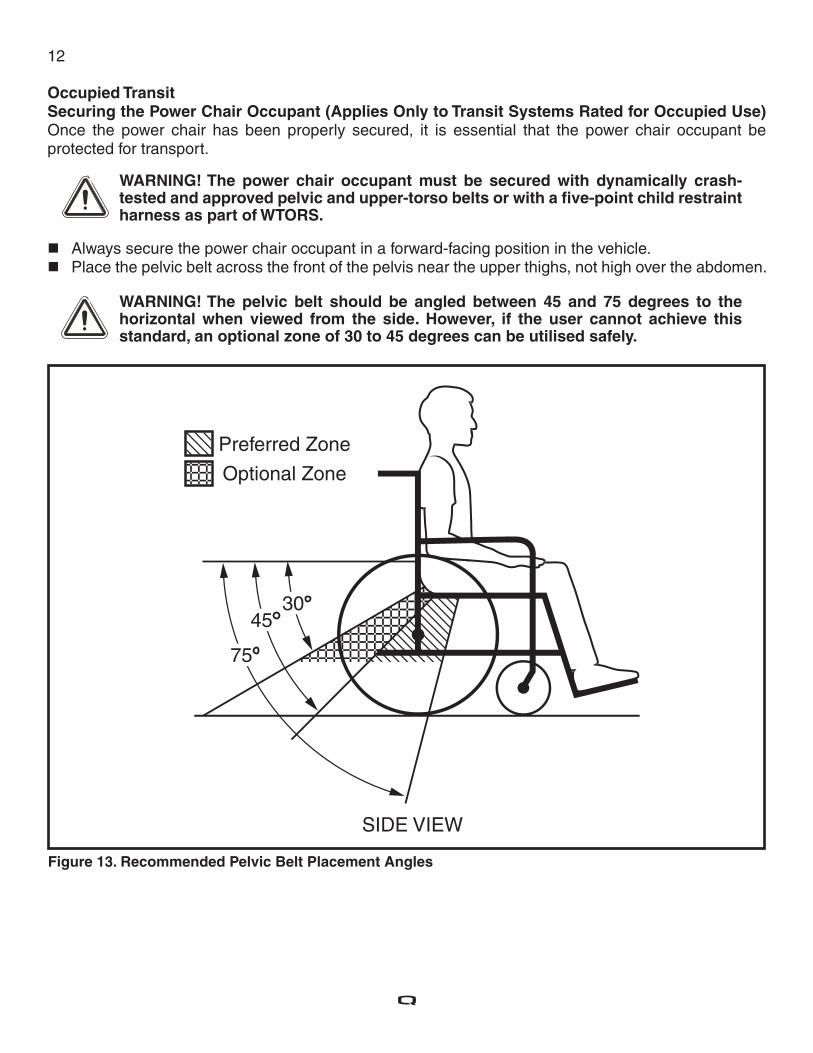
Always secure the power chair occupant in a forward-facing position in the vehicle. Place the pelvic belt across the front of the pelvis near the upper thighs, not high over the abdomen.
WARNING! The pelvic belt should be angled between 45 and 75 degrees to the horizontal when viewed from the side. However, if the user cannot achieve this standard, an optional zone of 30 to 45 degrees can be utilised safely.
Figure 13. Recommended Pelvic Belt Placement Angles
13
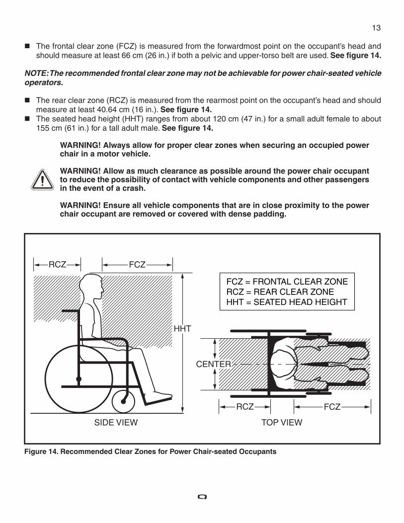
The frontal clear zone (FCZ) is measured from the forwardmost point on the occupant’s head and should measure at least 66 cm (26 in.) if both a pelvic and upper-torso belt are used. See fi gure 14.
NOTE: The recommended frontal clear zone may not be achievable for power chair-seated vehicle operators.
The rear clear zone (RCZ) is measured from the rearmost point on the occupant’s head and should measure at least 40.64 cm (16 in.). See fi gure 14.
The seated head height (HHT) ranges from about 120 cm (47 in.) for a small adult female to about 155 cm (61 in.) for a tall adult male. See fi gure 14.
WARNING! Always allow for proper clear zones when securing an occupied power chair in a motor vehicle.
WARNING! Allow as much clearance as possible around the power chair occupant to reduce the possibility of contact with vehicle components and other passengers in the event of a crash.
WARNING! Ensure all vehicle components that are in close proximity to the power chair occupant are removed or covered with dense padding.
Figure 14. Recommended Clear Zones for Power Chair-seated Occupants
14
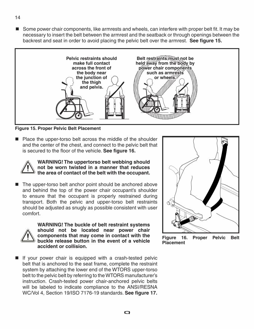
Some power chair components, like armrests and wheels, can interfere with proper belt fi t. It may be necessary to insert the belt between the armrest and the seatback or through openings between the backrest and seat in order to avoid placing the pelvic belt over the armrest. See fi gure 15.
Pelvic restraints shouldmake full contact
across the front ofthe body nearthe junction of
the thighand pelvis.
Belt restraints must not beheld away from the body by
power chair componentssuch as armrests
or wheels.
Belt restraints must not beheld away from the body by
power chair componentssuch as armrests
or wheels.
Figure 15. Proper Pelvic Belt Placement
Figure 16. Proper Pelvic Belt Placement
Place the upper-torso belt across the middle of the shoulder and the center of the chest, and connect to the pelvic belt that is secured to the fl oor of the vehicle. See fi gure 16.
WARNING! The uppertorso belt webbing shouldnot be worn twisted in a manner that reduces the area of contact of the belt with the occupant.
The upper-torso belt anchor point should be anchored above and behind the top of the power chair occupant’s shoulder to ensure that the occupant is properly restrained during transport. Both the pelvic and upper-torso belt restraints should be adjusted as snugly as possible consistent with user comfort.
WARNING! The buckle of belt restraint systems should not be located near power chair components that may come in contact with the buckle release button in the event of a vehicle accident or collision.
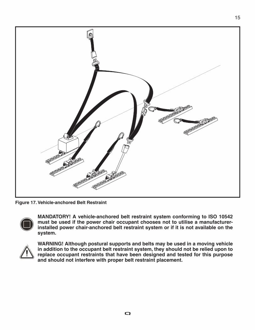
If your power chair is equipped with a crash-tested pelvic belt that is anchored to the seat frame, complete the restraint system by attaching the lower end of the WTORS upper-torso belt to the pelvic belt by referring to the WTORS manufacturer’s instruction. Crash-tested power chair-anchored pelvic belts will be labeled to indicate compliance to the ANSI/RESNA WC/Vol 4, Section 19/ISO 7176-19 standards. See fi gure 17.
15
MANDATORY! A vehicle-anchored belt restraint system conforming to ISO 10542 must be used if the power chair occupant chooses not to utilise a manufacturer-installed power chair-anchored belt restraint system or if it is not available on the system.
WARNING! Although postural supports and belts may be used in a moving vehicle in addition to the occupant belt restraint system, they should not be relied upon to replace occupant restraints that have been designed and tested for this purpose and should not interfere with proper belt restraint placement.
Figure 17. Vehicle-anchored Belt Restraint
16
Important Points to Remember
MANDATORY! Read and follow all manufacturer’s instructions, including the product owner’s manual.
MANDATORY! Any WTORS or power chair involved in a vehicle crash should be replaced.
WARNING! The power chair seatback should be positioned at an angle of no more than 30 degrees to the vertical. If a greater recline angle is required, the upper-torso belt anchor point should be moved rearward along the vehicle’s sidewall to ensure that the belt maintains contact with the power chair occupant’s shoulder and chest.
WARNING! Visually inspect all WTORS equipment according to WTORS manufacturer’s instructions on a regular basis, and have worn or broken components replaced immediately. Ensure anchorage track is free of dirt and debris.
WARNING! Remove hard trays and stow or secure them elsewhere in the vehicle to reduce the chance of power chair occupant injury from contact with the tray.
WARNING! Consider using foam trays in place of rigid trays during vehicle transport. If that is not possible, place dense foam padding between the power chair occupant and the tray, and make sure that the tray is securely attached to the power chair so that it will not break loose and cause injury to other occupants in a crash.
WARNING! Ensure the power chair occupant is properly positioned to protect the neck during rear impact.
WARNING! Secure all removable accessories, including clothing guards, medical and other equipment to the power chair or vehicle, to prevent injury during a crash.
WARNING! If head and neck support is required during travel, use a soft, light neck collar as they are less likely to cause neck injury in a crash. Do not attach the soft collar to the power chair or seating system.
Transit Securement SystemThe following components of the transit securement package must be compliant to ISO 10542 standards and must be installed according to the manufacturer’s instructions.
Wheelchair Tie-down and Occupant Restraint System (WTORS) 4-point power chair tie-down system with an integrated 3-point occupant restraint Tie-down end fi ttings WTORS securement points Occupant restraint securement points
NOTE: To obtain a copy of ISO 7176-19 or ISO 10542 visit www.iso.org.
17
Pride Transit Securement Package Declarations
MANDATORY! A belt restraint system with both pelvic and upper-torso belts must be used to protect the power chair occupant and minimise the likelihood of injury caused by contact with the vehicle during a crash or sudden braking.
The occupied power chair was dynamically tested in a forward-facing position with the surrogate occupant restrained by both pelvic and upper-torso belts and conforms with ISO 10542 requirements.
Appendix: Declarations

18 Notes

54 Contents
Copyright 2016INFMANU3661/Rev I/October 2016
Introduction .........................................................................................................................................3
Label Information ...............................................................................................................................4
Defi nitions ............................................................................................................................................4
User Safety Information ......................................................................................................................5
Protocols and Procedures ...................................................................................................................5
Securing the Power Chair ....................................................................................................................6
Occupied Transit.....................................................................................................................................12
Transit Securement System ..............................................................................................................16
Important Points to Remember .........................................................................................................16
Appendix: Declarations .....................................................................................................................17
USA401 York AvenueDuryea, PA 18642
Canada5096 South Service RoadBeamsville, Ontario L0R 1B3
UK32 Wedgwood RoadBicester, Oxfordshire OX26 4ULwww.quantumrehab.co.uk
Australia20-24 Apollo DriveHallam, Victoria 3803www.quantumrehab.com.au
New Zealand38 Lansford CrescentAvondaleAuckland, New Zealand 1007www.pridemobility.co.nz
ItalyVia del Progresso, ang. Via del LavoroLoc. Prato della Corte00065 Fiano Romano (RM)www.quantumrehab-italia.it
B.V.Castricummer Werf 261901 RW CastricumThe Netherlandswww.quantumrehab.eu
www.quantumrehab.com
Basic Operation Instructions
Transit Securement System
Including Models: Quantum 600 Sport, Quantum 600 Sport HD, Quantum 6000, Artemis, Athena, Quantum 600, Quantum 600XL, Quantum 610, Q6 Edge, Q6 Edge HD, Q6 Edge 2.0, Q6 Edge 2.0 equipped with iLevel ®, Aspen, Jazzy Air, Q4 equipped with a TB-Flex Seat, Q6 Edge HD, Jazzy 600 ES, Fusion, Lightning, Sparky, Quantum 1420, Jazzy 1121 and Pride LX


![Powerline Communication - planet.com.t1].pdf · PLANET makes no commitment to update or keep current the information in this User’s Manual, and reserves the right to make improvements](https://img.pdfslide.net/doc/110x75/5f249ba7076a0477bc57ad2b/powerline-communication-1pdf-planet-makes-no-commitment-to-update-or-keep.jpg)