Embed Size (px)
Citation preview
7/28/2019 PP 134-138 Simulation & Analysis of Sigma-Delta AD Converter Using VHDL-AMS
http://slidepdf.com/reader/full/pp-134-138-simulation-analysis-of-sigma-delta-ad-converter-using-vhdl-ams 1/5
International Journal of Scientific Engineering and Technology (ISSN : 2277-1581)
www.ijset.com, Volume No.1, Issue No.2 pg:134-138 01 April 2012
134
Simulation & Analysis of Sigma-Delta A/D Converter using VHDL-AMS
Prerna Gupta, Head & Prof. Rita Jain
Dept. of Electronics & Telecommunication Engg. LNCT Bhopal (M.P.) India
Abstract: Analog to digital converter is a
fundamental component for digital processors
since every signal which needs to be processed
using digi tal algor ithms requir es the digi tal data.
There are many dif ferent types of A/D converters
are available but the sigma delta A/D converter
has their unique advantage over others as they
have onl y 10 to 15 percent analog components and
rest are digi tal . This makes it good candidate when
the A/D needs to in tegrate with the DSP in single
chip, but the integration of two domains creates
diff icul ty to evaluate the behavior of A/D using
normal simulators hence special simulators call ed
analog and mixed signal simulators are required
in this paper we presented the detail simulation
and analysis of sigma delta A/D using VHDL -
AMS.
Keywords: sigma delta A/D Converters, VHDL -
AMS.
1. Introduction
Signal processing is needed for almost every
electronic system, & the techniques of processing
can be broadly divided into two parts analog anddigital, the analog systems are relative bulkier, less
flexible and more sensitive to environmental
conditions in the past they were the only possible
choice because they don’t need the complex
processors and other related components which
were difficult to manufacture at that time, but the
advancements in chip manufacturing technology
making it possible to design powerful processors on
single chip and at cheaper cost. Nowadays the
digital processing is preferred because it can
overcome almost every problem faced by the analog
processing.
The Digital Processing requires the signal in digital
form hence for Digital Signal Processors needs
internal or external A/D converters for external it
could be of any type but for internal it is a totally
different case because it requires compatibility with
VLSI technology, in order to provide for monolithic
integration of both the analog and digital sections
on a single die. Since the Sigma Delta A/D
converters are based on digital filtering techniques
almost 90% of the die is implemented in digital
circuitry which enhances the prospect of
compatibility [1].
2. Sigma Delta A/D Converter
This section describes the different technical terms
and working of sigma delta A/D converter.
2.1 Sigma Delta Modulation
The work on sigma-delta modulation was developed
as an extension to the well established delta
modulation.
7/28/2019 PP 134-138 Simulation & Analysis of Sigma-Delta AD Converter Using VHDL-AMS
http://slidepdf.com/reader/full/pp-134-138-simulation-analysis-of-sigma-delta-ad-converter-using-vhdl-ams 2/5
International Journal of Scientific Engineering and Technology (ISSN : 2277-1581)
www.ijset.com, Volume No.1, Issue No.2 pg:134-138 01 April 2012
135
The arrangement shown in Figure 1 is called a
Sigma-Delta Modulator [1]. This structure, besides
being simpler, can be considered as being a
“smoothed version” of a 1-bit delta modulator.
Figure 1: Sigma Delta A/D Modulator.
The name Sigma-Delta modulator comes from
putting the integrator (sigma) in front of the delta
modulator. The quantization noise like delta
modulators, the S-D modulators use a simple coarse
quantizer (comparator). However, unlike delta
modulators, these systems encode the integral of the
signal itself and thus their performance is
insensitive to the rate of change of the signal.
Figure 2: Sigma Delta A/D Modulator Practical
Diagram.
2.2 Oversampling
The sigma delta A/D is an oversampling A/D
converter because the signal is sampled at much
higher than the Nyquist rate. The oversampling not
only helps for tracking the original signal but also
spreads the quantization noise over a larger band
which helps in reducing the noise and designing of
LPF the example can be considered as shown in
figure.
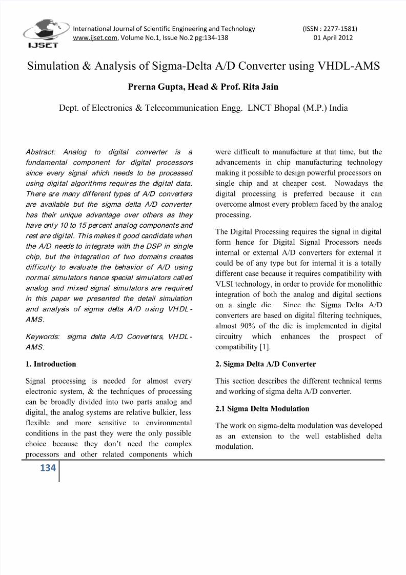
Figure 3: A sine wave of 500Hz is sampled at 1
Ks/s rate.
Figure 4: A sine wave of 500Hz is sampled at 100
Ks/s rate.
Now from figure 3 and 4 (without considering the
harmonic distortion) it is clear that the noise floor at
2Fs sampling rate is about 0.25 and reduces to 0.05
at 100Fs. It should be remember that the
oversampling not reducing the total error energy but
it distributes it over larger band.
2.3 Noise shaping
The noise shaping is a way of shaping the noise
spectrum. In sigma delta A/D it is used to shift the
7/28/2019 PP 134-138 Simulation & Analysis of Sigma-Delta AD Converter Using VHDL-AMS
http://slidepdf.com/reader/full/pp-134-138-simulation-analysis-of-sigma-delta-ad-converter-using-vhdl-ams 3/5
International Journal of Scientific Engineering and Technology (ISSN : 2277-1581)
www.ijset.com, Volume No.1, Issue No.2 pg:134-138 01 April 2012
136
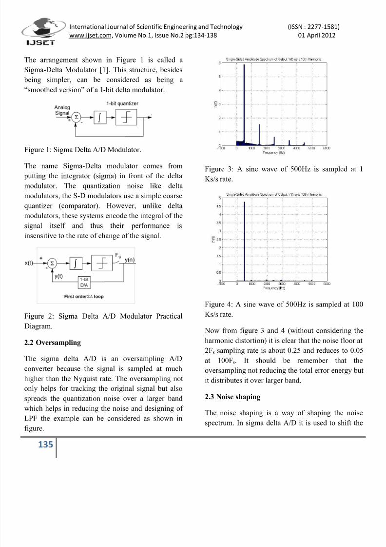
noise at spectrum at higher end. It is done by the
integrator present in the forward path of converter.
Figure 5: Descriptive Diagram of A/D converter.
The behavior of integrator as noise shaping element
can better understand by figure 5 here the
comparator is assumed as a noise producing
element. Now the effect of integrator for both inputs
X(s) and N(s) can be estimated by calculating the
transfer function for each input separately.
Transfer function when looking from X(s) and
considering N(s) = 0.
The equation 1 can be simplified to
This clearly shows the low-pass filter,
The transfer function when looking from N(s) and
considering X(s) = 0.
Simplifying the equation 3
This is high-pass filter.
The equations (1) and (4) shows that the integrator
acts differently for both and shifts the noise
spectrum towards high frequency.
2.4 Decimation
The process of decimation is used in a sigma delta
converter to eliminate redundant data at the output
The sampling theorem tells us that the sample rate
only needs to be 2 times the input signal bandwidth
in order to reliably reconstruct the input signa
without distortion. However, the input signal was
grossly oversampled by the sigma delta modulatorin order to reduce the quantization noise. Therefore
there is redundant data that can be eliminated
without introducing distortion to the conversion
result [2].
Figure 6: shows the decimation process by down
sampling the original signal in time domain.
Figure 7: shows the decimation process in
frequency domain.
7/28/2019 PP 134-138 Simulation & Analysis of Sigma-Delta AD Converter Using VHDL-AMS
http://slidepdf.com/reader/full/pp-134-138-simulation-analysis-of-sigma-delta-ad-converter-using-vhdl-ams 4/5
International Journal of Scientific Engineering and Technology (ISSN : 2277-1581)
www.ijset.com, Volume No.1, Issue No.2 pg:134-138 01 April 2012
137
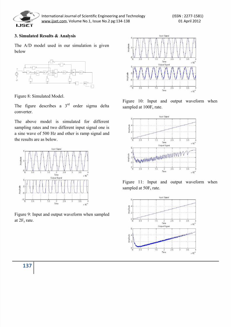
3. Simulated Results & Analysis
The A/D model used in our simulation is given
below
Figure 8: Simulated Model.
The figure describes a 3rd
order sigma delta
converter.
The above model is simulated for different
sampling rates and two different input signal one is
a sine wave of 500 Hz and other is ramp signal and
the results are as below.
Figure 9: Input and output waveform when sampled
at 2Fs rate.
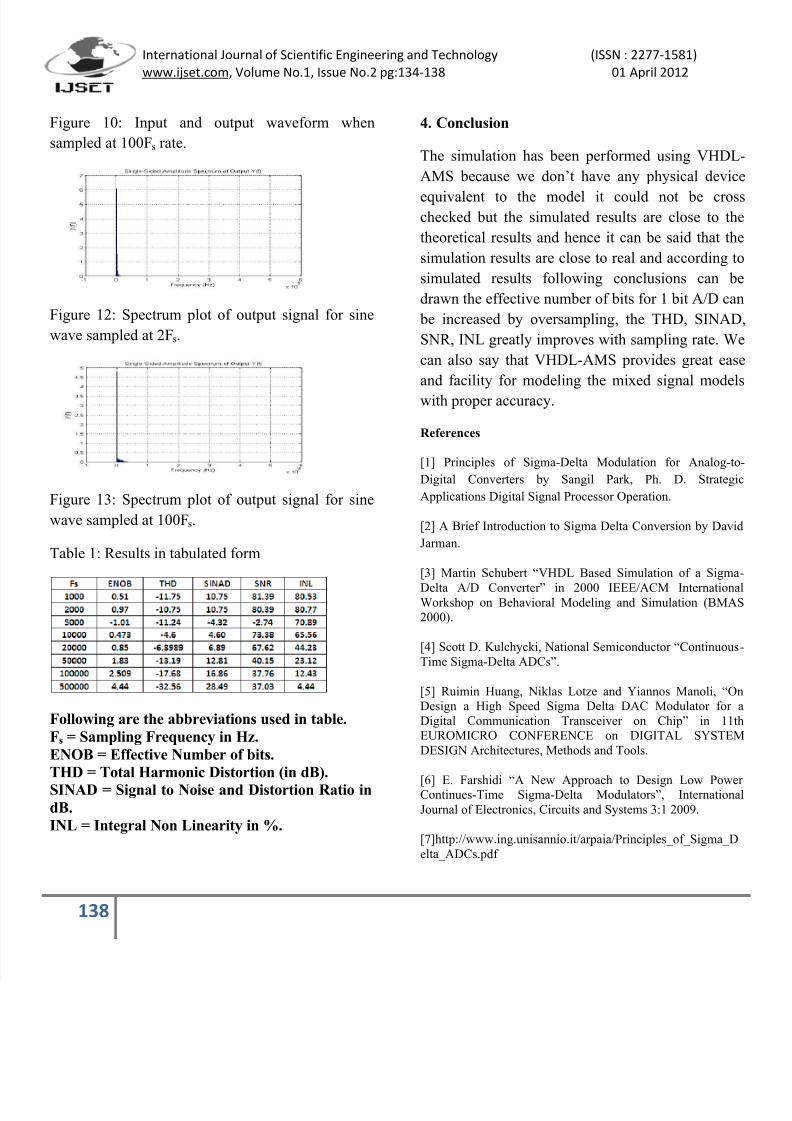
Figure 10: Input and output waveform when
sampled at 100Fs rate.
Figure 11: Input and output waveform when
sampled at 50Fs rate.
7/28/2019 PP 134-138 Simulation & Analysis of Sigma-Delta AD Converter Using VHDL-AMS
http://slidepdf.com/reader/full/pp-134-138-simulation-analysis-of-sigma-delta-ad-converter-using-vhdl-ams 5/5
International Journal of Scientific Engineering and Technology (ISSN : 2277-1581)
www.ijset.com, Volume No.1, Issue No.2 pg:134-138 01 April 2012
138
Figure 10: Input and output waveform when
sampled at 100Fs rate.
Figure 12: Spectrum plot of output signal for sine
wave sampled at 2Fs.
Figure 13: Spectrum plot of output signal for sine
wave sampled at 100Fs.
Table 1: Results in tabulated form
Following are the abbreviations used in table.
Fs = Sampling Frequency in Hz.
ENOB = Effective Number of bits.
THD = Total Harmonic Distortion (in dB).
SINAD = Signal to Noise and Distortion Ratio indB.
INL = Integral Non Linearity in %.
4. Conclusion
The simulation has been performed using VHDL-
AMS because we don’t have any physical device
equivalent to the model it could not be crosschecked but the simulated results are close to the
theoretical results and hence it can be said that the
simulation results are close to real and according to
simulated results following conclusions can be
drawn the effective number of bits for 1 bit A/D can
be increased by oversampling, the THD, SINAD
SNR, INL greatly improves with sampling rate. We
can also say that VHDL-AMS provides great ease
and facility for modeling the mixed signal models
with proper accuracy.
References
[1] Principles of Sigma-Delta Modulation for Analog-to
Digital Converters by Sangil Park, Ph. D. Strategic
Applications Digital Signal Processor Operation.
[2] A Brief Introduction to Sigma Delta Conversion by David
Jarman.
[3] Martin Schubert “VHDL Based Simulation of a Sigma
Delta A/D Converter” in 2000 IEEE/ACM InternationalWorkshop on Behavioral Modeling and Simulation (BMAS
2000).
[4] Scott D. Kulchycki, National Semiconductor “Continuous
Time Sigma-Delta ADCs”.
[5] Ruimin Huang, Niklas Lotze and Yiannos Manoli, “On
Design a High Speed Sigma Delta DAC Modulator for a
Digital Communication Transceiver on Chip” in 11th
EUROMICRO CONFERENCE on DIGITAL SYSTEM
DESIGN Architectures, Methods and Tools.
[6] E. Farshidi “A New Approach to Design Low PowerContinues-Time Sigma-Delta Modulators”, Internationa
Journal of Electronics, Circuits and Systems 3:1 2009.
[7]http://www.ing.unisannio.it/arpaia/Principles_of_Sigma_D
elta_ADCs.pdf

![ATA6560 - CAN Transceiver VHDL-AMS Model (Level 2)ww1.microchip.com/...9396_ATA6560-CAN-Transceiver-VHDL-AMS-M… · ATAN0132 [APPLICATION NOTE] 3 9396A–AUTO–06/15 1. Implementation](https://img.pdfslide.net/doc/110x75/5b88e79e7f8b9a435b8ec162/ata6560-can-transceiver-vhdl-ams-model-level-2ww1-atan0132-application.jpg)


![VHDL-AMS based modeling and simulation of mixed …technology problems is VHDL-AMS [6–8]. This high-level hardware description language is an IEEE standard and extension of a digital](https://img.pdfslide.net/doc/110x75/5e4e0bacbd0d724aef12c29f/vhdl-ams-based-modeling-and-simulation-of-mixed-technology-problems-is-vhdl-ams.jpg)