Embed Size (px)
Citation preview
1
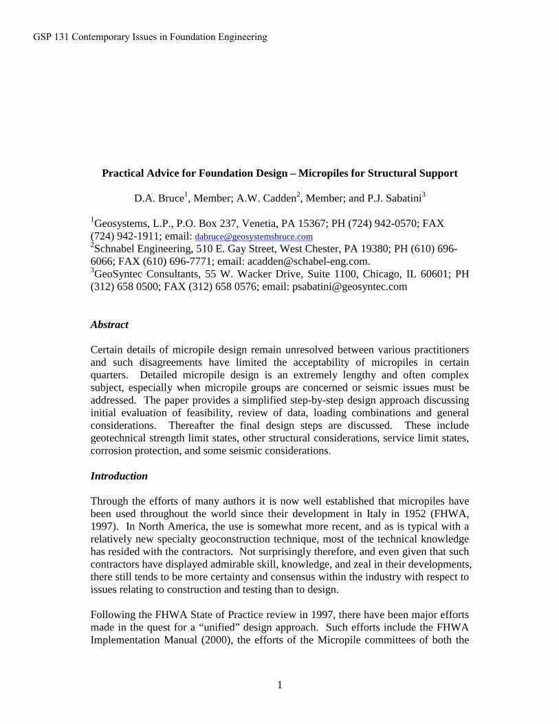
Practical Advice for Foundation Design – Micropiles for Structural Support
D.A. Bruce1, Member; A.W. Cadden2, Member; and P.J. Sabatini3
1Geosystems, L.P., P.O. Box 237, Venetia, PA 15367; PH (724) 942-0570; FAX (724) 942-1911; email: [email protected] Engineering, 510 E. Gay Street, West Chester, PA 19380; PH (610) 696-6066; FAX (610) 696-7771; email: [email protected] Consultants, 55 W. Wacker Drive, Suite 1100, Chicago, IL 60601; PH (312) 658 0500; FAX (312) 658 0576; email: [email protected]
Abstract
Certain details of micropile design remain unresolved between various practitioners and such disagreements have limited the acceptability of micropiles in certain quarters. Detailed micropile design is an extremely lengthy and often complex subject, especially when micropile groups are concerned or seismic issues must be addressed. The paper provides a simplified step-by-step design approach discussing initial evaluation of feasibility, review of data, loading combinations and general considerations. Thereafter the final design steps are discussed. These include geotechnical strength limit states, other structural considerations, service limit states, corrosion protection, and some seismic considerations.
Introduction
Through the efforts of many authors it is now well established that micropiles have been used throughout the world since their development in Italy in 1952 (FHWA, 1997). In North America, the use is somewhat more recent, and as is typical with a relatively new specialty geoconstruction technique, most of the technical knowledge has resided with the contractors. Not surprisingly therefore, and even given that such contractors have displayed admirable skill, knowledge, and zeal in their developments, there still tends to be more certainty and consensus within the industry with respect to issues relating to construction and testing than to design.
Following the FHWA State of Practice review in 1997, there have been major efforts made in the quest for a “unified” design approach. Such efforts include the FHWA Implementation Manual (2000), the efforts of the Micropile committees of both the
GSP 131 Contemporary Issues in Foundation Engineering
2
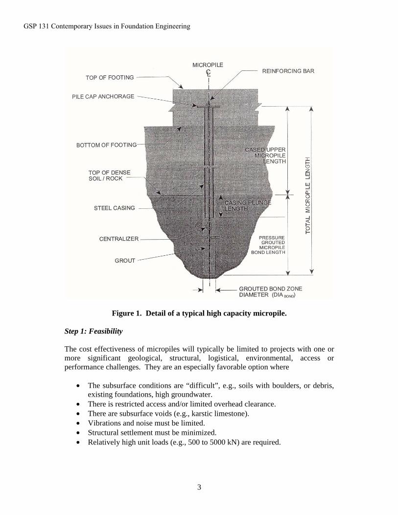
ADSC (International Association of Foundation Drilling), and DFI (The Deep Foundations Institute), and the work products of the IWM (International Workshop on Micropiles) meetings in Seattle (1997), Ube (1998), Turku (2000), Lille (2001), Venice (2002), and Seattle again (2003). This brief presentation of a practical design approach is drawn from a new manual being prepared as a basis for a micropile short course to be taught to the various Departments of Transportation nationwide. It follows the multi-step approach shown in Table 1, and relates to the typical composite high capacity pile shown schematically in Figure 1.
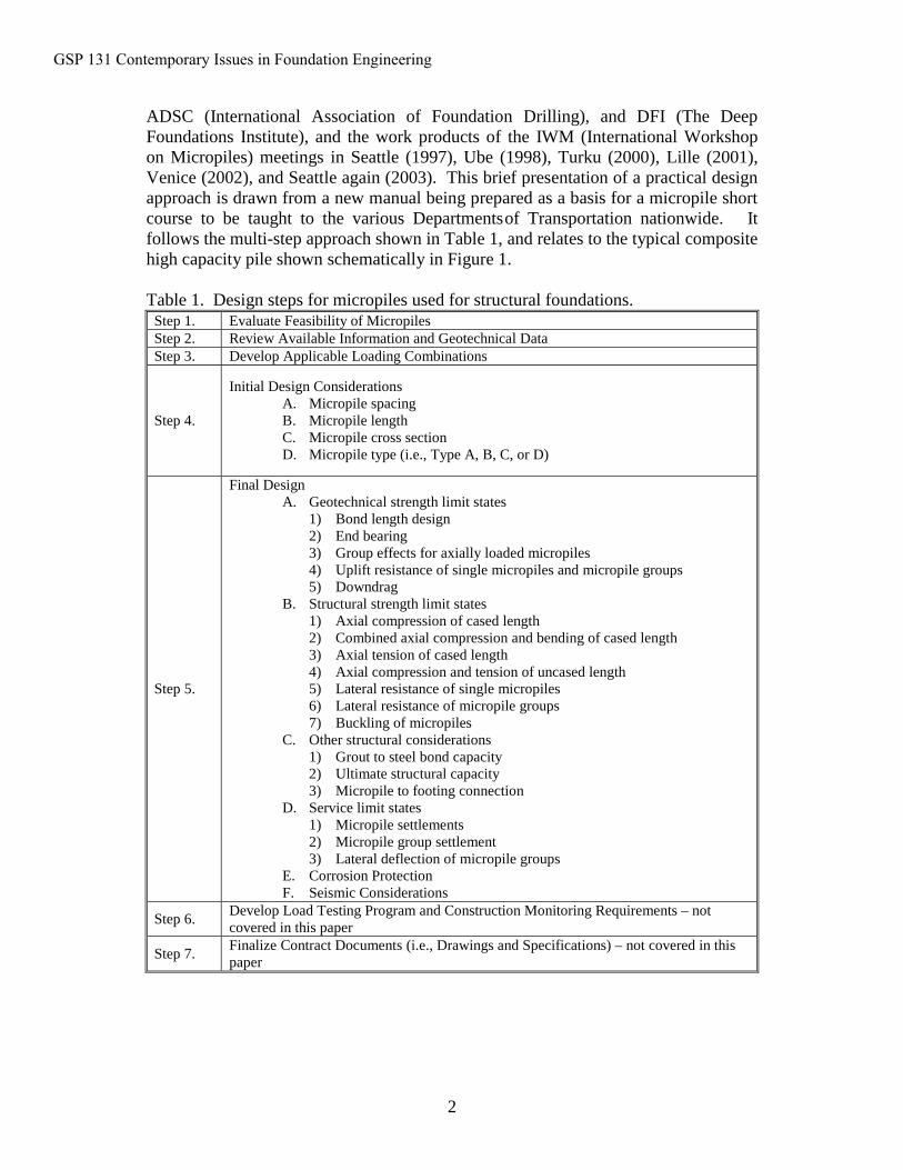
Table 1. Design steps for micropiles used for structural foundations.Step 1. Evaluate Feasibility of Micropiles Step 2. Review Available Information and Geotechnical DataStep 3. Develop Applicable Loading Combinations
Step 4.
Initial Design ConsiderationsA. Micropile spacingB. Micropile lengthC. Micropile cross sectionD. Micropile type (i.e., Type A, B, C, or D)
Step 5.
Final DesignA. Geotechnical strength limit states
1) Bond length design2) End bearing3) Group effects for axially loaded micropiles4) Uplift resistance of single micropiles and micropile groups5) Downdrag
B. Structural strength limit states1) Axial compression of cased length2) Combined axial compression and bending of cased length3) Axial tension of cased length4) Axial compression and tension of uncased length5) Lateral resistance of single micropiles6) Lateral resistance of micropile groups7) Buckling of micropiles
C. Other structural considerations1) Grout to steel bond capacity2) Ultimate structural capacity 3) Micropile to footing connection
D. Service limit states1) Micropile settlements2) Micropile group settlement3) Lateral deflection of micropile groups
E. Corrosion ProtectionF. Seismic Considerations
Step 6. Develop Load Testing Program and Construction Monitoring Requirements – not covered in this paper
Step 7. Finalize Contract Documents (i.e., Drawings and Specifications) – not covered in this paper
GSP 131 Contemporary Issues in Foundation Engineering
3
Figure 1. Detail of a typical high capacity micropile.
Step 1: Feasibility
The cost effectiveness of micropiles will typically be limited to projects with one or more significant geological, structural, logistical, environmental, access or performance challenges. They are an especially favorable option where
• The subsurface conditions are “difficult”, e.g., soils with boulders, or debris, existing foundations, high groundwater.
• There is restricted access and/or limited overhead clearance.• There are subsurface voids (e.g., karstic limestone).• Vibrations and noise must be limited.• Structural settlement must be minimized.• Relatively high unit loads (e.g., 500 to 5000 kN) are required.
GSP 131 Contemporary Issues in Foundation Engineering
4
Step 2: Review All Available Project Information and Geotechnical Data
Such data are well known to all foundation engineers and represent the same scope as for micropiles. For guidance regarding the planning and execution of subsurface exploration programs (AASHTO (1988), FHWA/NHI (2001), and FHWA (2002) documents apply. Particular care should be paid to studying the project-specific factors, e.g., liquefiable zones, expansive/dispersive soil deposits, and hazardous materials. Minimum guidelines for boring spacings are provided – as a first step – in Table 2.
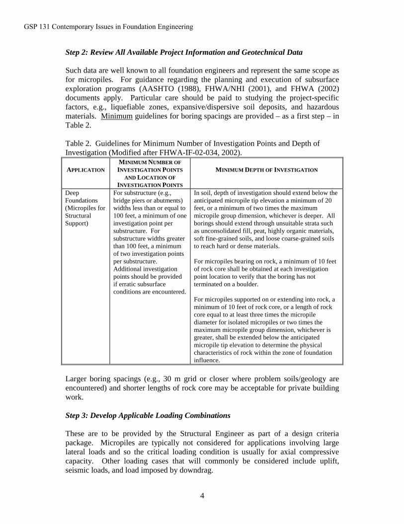
Table 2. Guidelines for Minimum Number of Investigation Points and Depth of Investigation (Modified after FHWA-IF-02-034, 2002).
APPLICATIONMINIMUM NUMBER OF INVESTIGATION POINTS
AND LOCATION OF INVESTIGATION POINTS
MINIMUM DEPTH OF INVESTIGATION
Deep Foundations(Micropiles for Structural Support)
For substructure (e.g., bridge piers or abutments) widths less than or equal to 100 feet, a minimum of one investigation point per substructure. For substructure widths greater than 100 feet, a minimum of two investigation points per substructure. Additional investigation points should be provided if erratic subsurface conditions are encountered.
In soil, depth of investigation should extend below the anticipated micropile tip elevation a minimum of 20 feet, or a minimum of two times the maximum micropile group dimension, whichever is deeper. All borings should extend through unsuitable strata such as unconsolidated fill, peat, highly organic materials, soft fine-grained soils, and loose coarse-grained soils to reach hard or dense materials.
For micropiles bearing on rock, a minimum of 10 feet of rock core shall be obtained at each investigation point location to verify that the boring has not terminated on a boulder.
For micropiles supported on or extending into rock, a minimum of 10 feet of rock core, or a length of rock core equal to at least three times the micropile diameter for isolated micropiles or two times the maximum micropile group dimension, whichever is greater, shall be extended below the anticipated micropile tip elevation to determine the physical characteristics of rock within the zone of foundation influence.
Larger boring spacings (e.g., 30 m grid or closer where problem soils/geology are encountered) and shorter lengths of rock core may be acceptable for private buildingwork.
Step 3: Develop Applicable Loading Combinations
These are to be provided by the Structural Engineer as part of a design criteria package. Micropiles are typically not considered for applications involving large lateral loads and so the critical loading condition is usually for axial compressive capacity. Other loading cases that will commonly be considered include uplift, seismic loads, and load imposed by downdrag.
GSP 131 Contemporary Issues in Foundation Engineering
5
Step 4: Initial Design Considerations
4.1 Section of Spacing. Whether used for small unit loads (e.g., through existing foundations) or higher unit loads (e.g., for a new footing), the minimum spacing should be at least 3 micropile diameters. This criterion was originally developed for driven piles, and it allows for potential deviations in drilling over significant depthsand eliminates negative group effects between adjacent micropiles.
4.2 Selection of Length. A minimum bond length may be prescribed in the Contract Documents. However, as for ground anchors, the actual bond stresses mobilized are sensitive to the construction technique, inter al., and so the actual bond length is often determined by the Contractor. The bond length must, however, be subject to satisfactory load testing results prior to production.
If lateral loads are present, analyses will be necessary to establish the required depth to provide fixity. Total length will also be controlled by the depths necessary to resistdowndrag and uplift forces, and to provide additional lateral resistance if scour is a consideration.
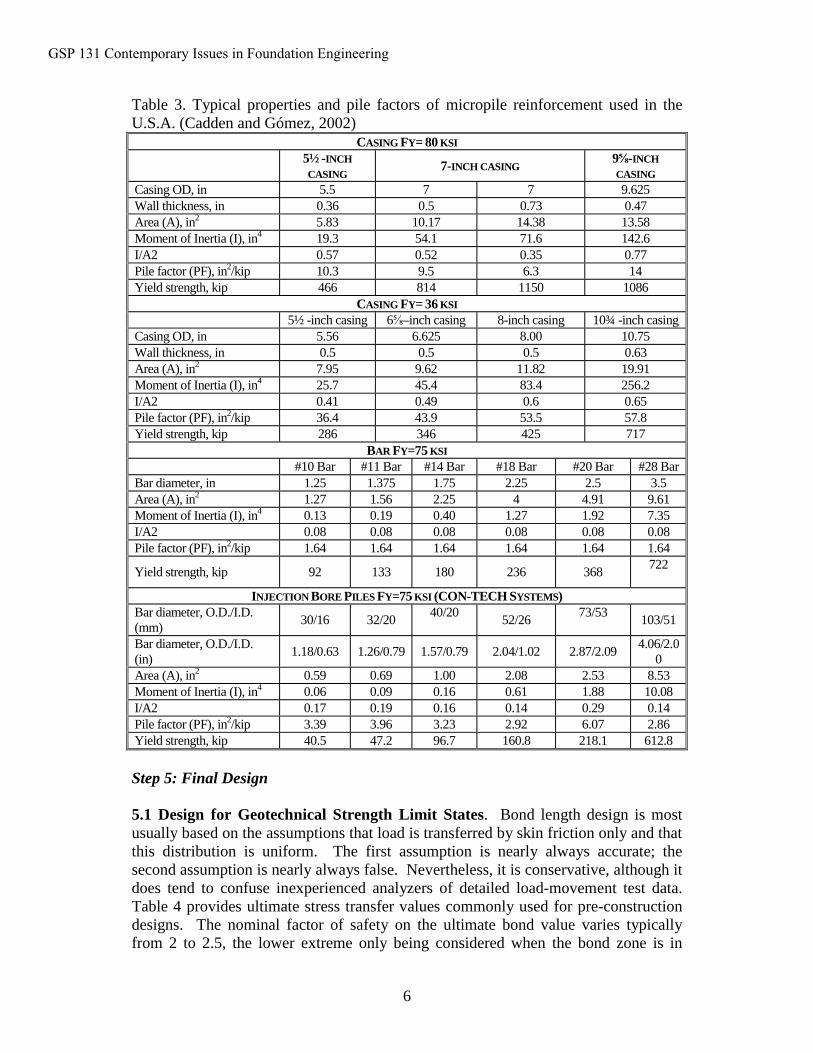
4.3 Selection of Micropile Cross Section. For preliminary sizing, the micropile cross section will be selected based on a rough estimate of the required structural section capable of resisting the design loads. Also, the use of common casing sizes ispreferred to avoid delays associated with material availability. Currently, the most common casing sizes in the U.S. are 141 mm (5½ in) and 178 mm (7 in) with a nominal yield stress of 552 MPa (80 ksi) with the 178-mm (7-inch) casing being the most common. These sizes refer to the outside diameter of the casing. Table 3provides a summary of material properties for common micropile reinforcement. Other sizes are also available.
4.4 Selection of Micropile Type. A description of the various micropile types (Type A, B, C, and D) is provided in other publications (e.g., Bruce et al., 1997). The selection of the micropile type will usually be left to the discretion of the contractor. As part of the request for bid, however, the Owner must insist that the Contractor provide information on their proposed methods of drilling and grouting. Based on previous project experience, the Owner may wish to disallow certain drilling techniques based on project-specific constraints. For example, the need to limit surface ground movements for a project involving cohesionless ground may preclude the use of certain drilling techniques known to increase the potential for soil caving.
The Owner should provide specific performance criteria (e.g., permissible movements of structures) as part of the bid package so that the Contractor can select an appropriate drilling and grouting procedure, as well as pile stiffness, to satisfy the overall project goals.
GSP 131 Contemporary Issues in Foundation Engineering
6
Table 3. Typical properties and pile factors of micropile reinforcement used in the U.S.A. (Cadden and Gómez, 2002)
CASING FY= 80 KSI
5½ -INCH CASING
7-INCH CASING9⅝-INCH CASING
Casing OD, in 5.5 7 7 9.625Wall thickness, in 0.36 0.5 0.73 0.47Area (A), in2 5.83 10.17 14.38 13.58Moment of Inertia (I), in4 19.3 54.1 71.6 142.6I/A2 0.57 0.52 0.35 0.77Pile factor (PF), in2/kip 10.3 9.5 6.3 14Yield strength, kip 466 814 1150 1086
CASING FY= 36 KSI
5½ -inch casing 6⅝–inch casing 8-inch casing 10¾ -inch casingCasing OD, in 5.56 6.625 8.00 10.75Wall thickness, in 0.5 0.5 0.5 0.63Area (A), in2 7.95 9.62 11.82 19.91Moment of Inertia (I), in4 25.7 45.4 83.4 256.2I/A2 0.41 0.49 0.6 0.65Pile factor (PF), in2/kip 36.4 43.9 53.5 57.8Yield strength, kip 286 346 425 717
BAR FY=75 KSI
#10 Bar #11 Bar #14 Bar #18 Bar #20 Bar #28 BarBar diameter, in 1.25 1.375 1.75 2.25 2.5 3.5Area (A), in2 1.27 1.56 2.25 4 4.91 9.61Moment of Inertia (I), in4 0.13 0.19 0.40 1.27 1.92 7.35I/A2 0.08 0.08 0.08 0.08 0.08 0.08Pile factor (PF), in2/kip 1.64 1.64 1.64 1.64 1.64 1.64
Yield strength, kip 92 133 180 236 368722
INJECTION BORE PILES FY=75 KSI (CON-TECH SYSTEMS)Bar diameter, O.D./I.D. (mm)
30/16 32/2040/20
52/2673/53
103/51
Bar diameter, O.D./I.D. (in)
1.18/0.63 1.26/0.79 1.57/0.79 2.04/1.02 2.87/2.094.06/2.0
0Area (A), in2 0.59 0.69 1.00 2.08 2.53 8.53Moment of Inertia (I), in4 0.06 0.09 0.16 0.61 1.88 10.08I/A2 0.17 0.19 0.16 0.14 0.29 0.14Pile factor (PF), in2/kip 3.39 3.96 3.23 2.92 6.07 2.86Yield strength, kip 40.5 47.2 96.7 160.8 218.1 612.8
Step 5: Final Design
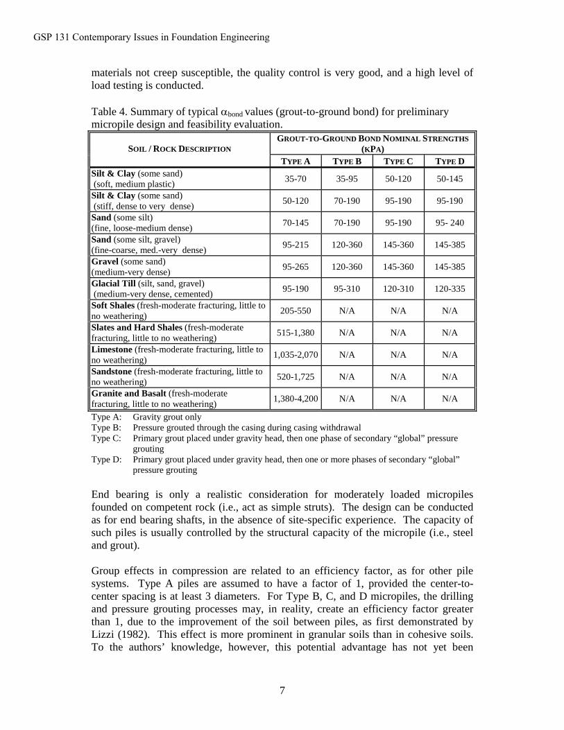
5.1 Design for Geotechnical Strength Limit States. Bond length design is most usually based on the assumptions that load is transferred by skin friction only and that this distribution is uniform. The first assumption is nearly always accurate; the second assumption is nearly always false. Nevertheless, it is conservative, although it does tend to confuse inexperienced analyzers of detailed load-movement test data. Table 4 provides ultimate stress transfer values commonly used for pre-construction designs. The nominal factor of safety on the ultimate bond value varies typically from 2 to 2.5, the lower extreme only being considered when the bond zone is in
GSP 131 Contemporary Issues in Foundation Engineering
7
materials not creep susceptible, the quality control is very good, and a high level of load testing is conducted.
Table 4. Summary of typical αbond values (grout-to-ground bond) for preliminary micropile design and feasibility evaluation.
GROUT-TO-GROUND BOND NOMINAL STRENGTHS (KPA)SOIL / ROCK DESCRIPTION
TYPE A TYPE B TYPE C TYPE DSilt & Clay (some sand) (soft, medium plastic)
35-70 35-95 50-120 50-145
Silt & Clay (some sand) (stiff, dense to very dense)
50-120 70-190 95-190 95-190
Sand (some silt)(fine, loose-medium dense)
70-145 70-190 95-190 95- 240
Sand (some silt, gravel)(fine-coarse, med.-very dense)
95-215 120-360 145-360 145-385
Gravel (some sand)(medium-very dense)
95-265 120-360 145-360 145-385
Glacial Till (silt, sand, gravel) (medium-very dense, cemented)
95-190 95-310 120-310 120-335
Soft Shales (fresh-moderate fracturing, little to no weathering)
205-550 N/A N/A N/A
Slates and Hard Shales (fresh-moderate fracturing, little to no weathering)
515-1,380 N/A N/A N/A
Limestone (fresh-moderate fracturing, little to no weathering)
1,035-2,070 N/A N/A N/A
Sandstone (fresh-moderate fracturing, little to no weathering)
520-1,725 N/A N/A N/A
Granite and Basalt (fresh-moderate fracturing, little to no weathering)
1,380-4,200 N/A N/A N/A
Type A: Gravity grout onlyType B: Pressure grouted through the casing during casing withdrawalType C: Primary grout placed under gravity head, then one phase of secondary “global” pressure
groutingType D: Primary grout placed under gravity head, then one or more phases of secondary “global”
pressure grouting
End bearing is only a realistic consideration for moderately loaded micropilesfounded on competent rock (i.e., act as simple struts). The design can be conducted as for end bearing shafts, in the absence of site-specific experience. The capacity of such piles is usually controlled by the structural capacity of the micropile (i.e., steel and grout).
Group effects in compression are related to an efficiency factor, as for other pile systems. Type A piles are assumed to have a factor of 1, provided the center-to-center spacing is at least 3 diameters. For Type B, C, and D micropiles, the drilling and pressure grouting processes may, in reality, create an efficiency factor greater than 1, due to the improvement of the soil between piles, as first demonstrated by Lizzi (1982). This effect is more prominent in granular soils than in cohesive soils. To the authors’ knowledge, however, this potential advantage has not yet been
GSP 131 Contemporary Issues in Foundation Engineering
8
exploited in North American practice, since this is a very complex issue which so far has not been rationalized to a sufficient degree.Uplift resistance calculations for single piles follow the same logic as for compression piles, given the “skin friction” load transfer mechanism. The value of load testing is particularly relevant in these considerations, especially when nominal safety factors approach 2. The design of groups of piles subject to uplift follows the method described by FHWA (1996) for driven piles (cohesionless soils) and driven piles (cohesive soils) to consider the group performance: these are well recognized and utilized procedures.
5.2 Design for Structural Strength Limit States. Although the structural design of micropiles is sufficiently different from more conventional drilled shafts or driven piles, local construction regulations and/or building codes may indirectly address micropile design and therefore need to be considered by the design engineer. However, the comprehensive structural design of micropiles will likely not be provided in these sources. Efforts are underway by organizations such as ADSC to add micropile-specific code sections in both the AASHTO and International Building Code (IBC).
The calculation of the allowable compression and bending capacity and calculation of the allowable tension capacity for the upper cased length of the micropile is discussed here. Since it is common for the upper cased length of the micropile to be located in a relatively weak upper soil zone, consideration of a laterally unsupported length is included in determination of the compression capacity of the micropile. This evaluation is consistent with methods used in structural steel ASD for beam-columns. Buckling of micropiles may be an important consideration for specific project conditions.
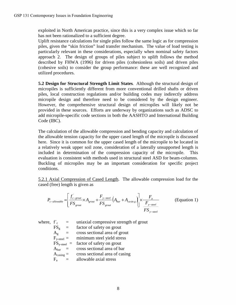
5.2.1 Axial Compression of Cased Length. The allowable compression load for the cased (free) length is given as
( )steely
steely
agcabar
grout
steelygrout
grout
groutcallowablec
FS
FF
AAFS
FA
FS
fP
−
−
−−− ×
++×= sin
'
(Equation 1)
where, f´c = uniaxial compressive strength of groutFSg = factor of safety on groutAg = cross sectional area of grout Fy-steel = minimum steel yield stressFSy-steel = factor of safety on groutAbar = cross sectional area of barAcasing = cross sectional area of casingFa = allowable axial stress
GSP 131 Contemporary Issues in Foundation Engineering
9
FSg as used in private work is typically 1/0.33, based on historical building codes. FHWA currently allows 1/0.4. FSsteel is taken typically as 0.4 by private bulding codes, and up to 0.47 by FHWA documents.
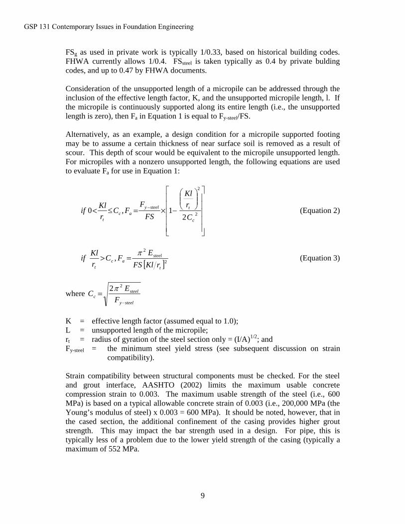
Consideration of the unsupported length of a micropile can be addressed through the inclusion of the effective length factor, K, and the unsupported micropile length, l. If the micropile is continuously supported along its entire length (i.e., the unsupported length is zero), then Fa in Equation 1 is equal to Fy-steel/FS.
Alternatively, as an example, a design condition for a micropile supported footing may be to assume a certain thickness of near surface soil is removed as a result of scour. This depth of scour would be equivalent to the micropile unsupported length. For micropiles with a nonzero unsupported length, the following equations are used to evaluate Fa for use in Equation 1:
−×=≤< −2
2
21,0
c
tsteelyac
t C
r
Kl
FS
FFC
r
Klif (Equation 2)
[ ]2
2
,t
steelac
t rKlFS
EFC
r
Klif
π=> (Equation 3)
where steely
steelc F
EC
−
=22π
K = effective length factor (assumed equal to 1.0);L = unsupported length of the micropile;rt = radius of gyration of the steel section only = (I/A)1/2; andFy-steel = the minimum steel yield stress (see subsequent discussion on strain
compatibility).
Strain compatibility between structural components must be checked. For the steel and grout interface, AASHTO (2002) limits the maximum usable concrete compression strain to 0.003. The maximum usable strength of the steel (i.e., 600 MPa) is based on a typical allowable concrete strain of 0.003 (i.e., 200,000 MPa (the Young’s modulus of steel) x 0.003 = 600 MPa). It should be noted, however, that inthe cased section, the additional confinement of the casing provides higher grout strength. This may impact the bar strength used in a design. For pipe, this is typically less of a problem due to the lower yield strength of the casing (typically a maximum of 552 MPa.
GSP 131 Contemporary Issues in Foundation Engineering
10
Regarding casing and bar, the area of the former is typically much larger than the latter. Thus the majority of the load (in the cased length) will be supported by the casing, requiring that the allowable yield stress of the bar be further reduced for strain compatibility between the pile elements.
In summary, strain compatibility requirements dictate that a smaller yield stress be used for the steel reinforcing bar and casing in the calculations. For compression loadings, this yield stress value (i.e., Fy-steel in Equation 1) should be the lesser of: (1) the yield stress of the reinforcing bar; (2) the yield stress of the steel casing; or (3) 600 MPa. A higher compression ultimate capacity could be utilized for the cased portion if documentation were to be provided to show that the grout within the casing could sustain strains larger than 0.003. Research is currently being sponsored by ADSC on this question.
An alternative method for computing allowable loads utilizing the transformed section of the micropile could be used. Such a method is beyond the scope of thispaper, but includes estimating allowable strains for each of the component materials.
5.2.2 Combined Axial Compression and Bending of Cased Length. In some cases, a micropile will be subject to both axial compression load and bending stresses. A combined stress evaluation is conducted, based on AASHTO (2002). Such an evaluation is not performed for the uncased length since micropiles are designed sothat bending stresses are negligible below the cased length since grout and a central bar would have little moment capacity.
5.2.3 Allowable Tension of Cased Length. The allowable tension load for the cased length is given as
( )gcabarsteelyallowablet AAFP sin55.0 +×= −− (Equation 4)
Note: Acasing must consider the reduced steel area at threads. A higher yield stress (compared to the minimum of the steel bar or casing previously discussed) may be utilized if the strains due to the working loads are shown to not cause permanent deformations in the threaded casing joints. This information should be based on laboratory testing of casing joints provided by the casing manufacturer. For tension loading without bending, it may be conservatively assumed that the reinforcing bar alone carries the tension load.
5.2.4 Axial Compression and Tension of Uncased Length. The allowablecompression load for the uncased length of a micropile is given as:
[ ]barbarygroutgroutcallowablec AFAfP ××+×= −−− 47.04.0 ' (Equation 5)
The allowable tension load for the uncased length of a micropile is given as:
GSP 131 Contemporary Issues in Foundation Engineering
11
barbaryallowablet AFP ×= −− 55.0 (Equation 6)
For the uncased portion of the pile, the reinforcing bar yield stress used in the calculations in compression must not exceed 600 MPa.
5.2.5 Lateral Resistance of Single Micropiles. The response of a single micropile to lateral loading at or near the ground surface is commonly evaluated using a “p-y analysis”. This will
• Determine the necessary penetration of the micropile to carry the loads at the micropile head without undergoing lateral deflection at the ground line which would result in excessive lateral movement of the supported structure;
• Determine the required micropile diameter, pipe casing and reinforcing steel sizes and strength properties, and grout strength to resist the design bending moment, shear force, and axial load that will be supported by the micropile; and
• Determine the deformation and rotation of the micropile in order to model the effects of foundation deformation on the performance of the structure.
Procedures for constructing p-y curves for various soil and water table conditions as well as static or cyclic loading conditions are provided in the COM 624P program documentation (Wang and Reese, 1993) and in the documentation for the program LPILE (Reese et al., 2000).
It is specifically noted that the development of a pile model, subsurface profile, and other input parameters for a p-y analysis is equivalent to that for a driven pile or drilled shaft. The reader is referred to FHWA-HI-97-013 and FHWA-IF-99-025 for specific modeling details related to lateral loading analysis.
Furthermore, it is common to find bars and casings installed in coupled sections, each perhaps as short as 1 m. Performance of the coupled steel in compression is not an issue of concern. Tensile and bending stresses, however, have a greater impact on the integrity of the casing at the joint location primarily because of the reduced thickness of the casing over the length of the threaded area. Currently, no specific testing standard exists for evaluating the tension or bending capacity of a threaded casing joint appropriate for micropile applications. If significant tension and/or bending forces are being considered for a micropile design, the Owner should require the contractor to provide data demonstrating the adequacy of the proposed joint detail. Since a common testing method does not exist, these data will need to be reviewed by a qualified engineer. As projects involving vertical micropiles subject to lateral forces become more commonplace, a means to evaluate allowable tensile and bending stresses for threaded joints will become necessary, especially since many casing providers in the U.S. have a slightly different proprietary threading detail.
GSP 131 Contemporary Issues in Foundation Engineering
12
Analytical results that discount these connections may be unconservative in the upper 1.5 to 3 m. The simple practical solution is therefore to either place additional steel section in the upper length, or to use a longer casing in the top section which would therefore develop acceptable bending resistance. Where a second concentric casing is used, joints should be staggered by 1 m vertically.
5.2.6 Lateral Resistance of Micropile Groups. Similar to other types of piles, micropile behavior in a group configuration is influenced by spacing between individual elements. The deflection of a pile group under a lateral load may be 2 to 3 times larger than the deflection of a single pile loaded to the same intensity. Holloway et al. (1981) and Brown et al. (1988) reported that piles in trailing rows of pile groups have significantly less resistance to a lateral load than piles in the lead row, and therefore exhibit greater deflections. This is due to the pile-soil-pile interaction that takes place in a pile group. The pile-soil-pile interaction results in the lateral capacity of a pile group being less than the sum of the lateral capacities of the individual piles comprising the group. Hence, laterally loaded pile groups have a group efficiency of less than 1. Based on experiments conducted as part of the FOREVER National Project on horizontally loaded micropile groups, the following conclusions were drawn:
• For in-line micropiles, group effects are negligible for micropile spacing between 6 to 7 diameters; and
• For micropiles arranged in a row (i.e., perpendicular to the direction of loading), group effects are negligible for micropile spacing just greater than 3 diameters.
The lateral capacity of an individual pile in a pile group is a function of its position in the group and the center to center pile spacing. Brown et al. (1998) proposed a p-multiplier, Pm, be used to modify the p-y curve of an individual pile based upon the piles row position. For piles in a given row, the same Pm value is applied to all p-y curves along the length of the pile. In a lateral load test of a 3 by 3 pile group in very dense sand with a center to center pile spacing of 3b, Brown found the leading row of piles had a Pm of 0.8 times that of an individual pile. The Pm values for the middle and back row of the group were 0.4 and 0.3, respectively.
A summary of additional laterally loaded driven pile group studies is provided in FHWA-HI-97-013 (1996). Also, preliminary results from the FOREVER project indicate that Pm multipliers for micropiles may be slightly higher than those recommended herein, however, only limited data from centrifuge testing is available at this time.
Micropiles can easily be inclined to provide additional resistance to lateral loading. Pile groups that contain inclined piles are relatively stiff and will undergo less lateral movement for a given load than for a system with the same number of vertical piles. However, this increased system stiffness also results in greater bending moments in the pile cap which is a concern, especially for highly seismic regions. Moreover,
GSP 131 Contemporary Issues in Foundation Engineering
13
inclined micropiles should not be used where the potential for ground settlement around the inclined micropile (e.g., downdrag) is a possibility.
5.2.7 Buckling of Micropiles. Micropile capacity is frequently dictated by the structural strength of the element, rather than by the geotechnical bond between the micropile grout and surrounding soils. Therefore, it is reasonable to believe that,where very soft soils or voids overly the bearing strata, buckling may potentially control the load-carrying capacity of a micropile. To address concerns regarding buckling of steel piles driven to rock, Bjerrum (1957) published results of buckling tests and related them to the methods available at the time. He presented results of load tests performed on piles with a variety of sections, including bars, rails, and H-sections. He concluded that even very soft soils could provide enough lateral restraint to prevent buckling of most pile sections.
The issue of buckling of micropiles has been the subject of attention of several researchers, including Mascardi (1970, 1982) and Gouvenot (1975). Their results seem to support Bjerrum’s conclusion that buckling is likely to occur only in soilswith very poor mechanical properties such as peat and soft clay. Experiments carried out by CalTrans (Brittsan and Speer, 1993) on high capacity micropiles installed through a very thick (33 m) deposit of San Francisco Bay Mud, and case histories of rock-socketed micropiles in karst (Cadden et al., 2001, Gómez et al., 2004) have further shown that micropiles can be successfully applied in a variety of “difficult” subsurface environments.
It cannot be inferred, however, that buckling in micropiles will never occur. Buckling of piles is a complex soil-pile interaction problem that involves the pile section and elastic properties, soil strength and stiffness, and the eccentricity of the applied load.
Equation 7 can be used to estimate the critical load, Pcr, of a pile (Bjerrum, 1957):
2
2
2
2
ππ lE
l
EIP s
cr += (Equation 7)
where:
E = modulus of elasticity of the pile material [force/area]I = minimum moment of inertia of the pile [length4]L = “unsupported” length of the pile [length]Es = modulus of lateral reaction of the soil [force/area], i.e., slope of p-y
diagram (not to be confused with modulus of subgrade reaction).
The term “unsupported” refers to the portion of the pile that is only subject to the lateral restraint provided by the soil. The first term of Equation 7 corresponds to Euler’s equation for buckling in columns. The second term reflects the contribution of the lateral restraint provided by the soil. Theoretically, buckling should only be a
GSP 131 Contemporary Issues in Foundation Engineering
14
concern for design of a micropile if the compression load that produces yielding of the pile material exceeds the value of Pcr.
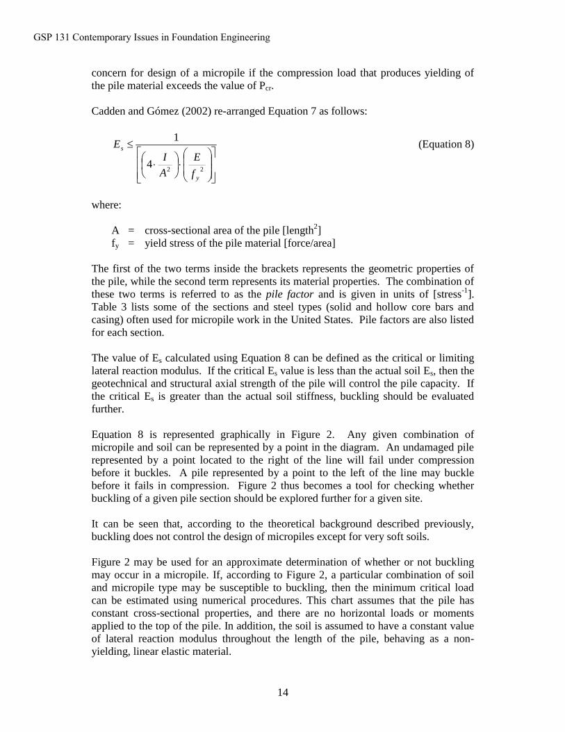
Cadden and Gómez (2002) re-arranged Equation 7 as follows:
⋅
⋅
≤
224
1
y
s
f
E
A
IE (Equation 8)
where:
A = cross-sectional area of the pile [length2]fy = yield stress of the pile material [force/area]
The first of the two terms inside the brackets represents the geometric properties of the pile, while the second term represents its material properties. The combination of these two terms is referred to as the pile factor and is given in units of [stress-1]. Table 3 lists some of the sections and steel types (solid and hollow core bars andcasing) often used for micropile work in the United States. Pile factors are also listed for each section.
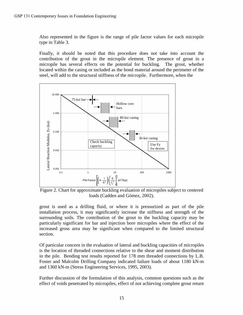
The value of Es calculated using Equation 8 can be defined as the critical or limiting lateral reaction modulus. If the critical Es value is less than the actual soil Es, then the geotechnical and structural axial strength of the pile will control the pile capacity. If the critical Es is greater than the actual soil stiffness, buckling should be evaluated further.
Equation 8 is represented graphically in Figure 2. Any given combination of micropile and soil can be represented by a point in the diagram. An undamaged pile represented by a point located to the right of the line will fail under compression before it buckles. A pile represented by a point to the left of the line may buckle before it fails in compression. Figure 2 thus becomes a tool for checking whether buckling of a given pile section should be explored further for a given site.
It can be seen that, according to the theoretical background described previously, buckling does not control the design of micropiles except for very soft soils.
Figure 2 may be used for an approximate determination of whether or not buckling may occur in a micropile. If, according to Figure 2, a particular combination of soil and micropile type may be susceptible to buckling, then the minimum critical load can be estimated using numerical procedures. This chart assumes that the pile has constant cross-sectional properties, and there are no horizontal loads or moments applied to the top of the pile. In addition, the soil is assumed to have a constant value of lateral reaction modulus throughout the length of the pile, behaving as a non-yielding, linear elastic material.
GSP 131 Contemporary Issues in Foundation Engineering
15
Also represented in the figure is the range of pile factor values for each micropile type in Table 3.
Finally, it should be noted that this procedure does not take into account the contribution of the grout in the micropile element. The presence of grout in a micropile has several effects on the potential for buckling. The grout, whether located within the casing or included as the bond material around the perimeter of the steel, will add to the structural stiffness of the micropile. Furthermore, when the
0.001
0.010
0.100
1.000
10.000
0.1 1 10 100 1000
Pile Factor, Fp (in2/Kip)
Late
ral R
eact
ion
Mod
ulus
, c (K
si)
80-ksi casing
36-ksi casing
75-ksi bar
Use Fy for design
Check buckling capacity
Es (
ksi)
Hollow core bars
/kip)(inf
E
A
I4FactorPile 2
2y
2
⋅⋅⋅⋅
⋅⋅⋅⋅
Lat
eral
Rea
ctio
n M
odul
us, E
s (k
si)
Figure 2. Chart for approximate buckling evaluation of micropiles subject to centered loads (Cadden and Gómez, 2002).
grout is used as a drilling fluid, or where it is pressurized as part of the pile installation process, it may significantly increase the stiffness and strength of the surrounding soils. The contribution of the grout to the buckling capacity may be particularly significant for bar and injection bore micropiles where the effect of the increased gross area may be significant when compared to the limited structural section.
Of particular concern in the evaluation of lateral and buckling capacities of micropiles is the location of threaded connections relative to the shear and moment distribution in the pile. Bending test results reported for 178 mm threaded connections by L.B. Foster and Malcolm Drilling Company indicated failure loads of about 1180 kN-m and 1360 kN-m (Stress Engineering Services, 1995, 2003).
Further discussion of the formulation of this analysis, common questions such as the effect of voids penetrated by micropiles, effect of not achieving complete grout return
GSP 131 Contemporary Issues in Foundation Engineering
16
to fill an annulus space, as well as several example calculations and case histories, can be found in the complete White Paper developed by the ADSC Micropile Committee and available through the ADSC Technical Library (Cadden and Gómez, 2002).
5.3 Other Structural Design Considerations.5.3.1 Grout to Steel Bond Capacity. The bond between the cement grout and the reinforcing steel bar allows the composite action of the micropile, and is the mechanism for transfer of the pile load from the reinforcing steel to the ground. Typical ultimate bond values range from 1.0 to 1.75 MPa for smooth bars and pipe, and 2.0 to 3.5 MPa for deformed bars (ACI 318).
In the majority of cases, grout-to-steel bond does not govern the pile design. The structural or geotechnical pile capacity typically governs.
As is the case with any reinforcement, the surface condition can affect the attainable bond. A film of rust may be beneficial, but the presence of loose debris or lubricant or paint is not desirable. Normal methods for the handling and storage of reinforcing bars apply to micropile construction. For the permanent casing that is also used to drill the hole, cleaning of the casing surface can occur during drilling, particularly in granular soils. Adequate cleaning of casing to be re-used in cohesive soils is essential to avoid reduction bond capacity.
5.3.2 Ultimate Structural Capacity. Micropile load testing may be carried to loads up to and, in some cases, greater than two times the design load. For load testing, maximum test loads should not exceed 80 percent of the ultimate structural capacity of the micropile, which is given by:
[ ]barbarygcagcaygroutgroutcncompressioult AfAfAfP ×+×+×= −−−− sinsin'85.0 (Equation 9)
[ ]barbarygcagcaytensionult AfAfP ×+×= −−− sinsin (Equation 10)
For some designs, the verification test pile(s) may require larger pile casing and reinforcing bar than the production micropiles. The resulting stiffer micropile can adequately confirm the grout-ground bond strength for production micropiles, but will likely not provide representative structural displacement behavior. The deflections measured for proof-tested micropiles at 100 percent of the design load will need to be relied upon to provide best estimate of structural deflections.
5.3.2 Micropile to Footing Connection. Unless a single micropile is used, a pile cap (footing) is necessary to spread the structure loads and any overturning moments to all the micropiles in the group. Reinforced concrete pile caps are designed in accordance with the AASHTO Standard Specifications for Highway Bridges or ACI 318.
GSP 131 Contemporary Issues in Foundation Engineering
17
The connection between the top of the micropile and the reinforced concrete pile cap can vary depending on the required capacity of the connection, the type of pile reinforcement, and the details of the pile cap. Some connections need only work in compression, while others will be required to work in compression and tension.
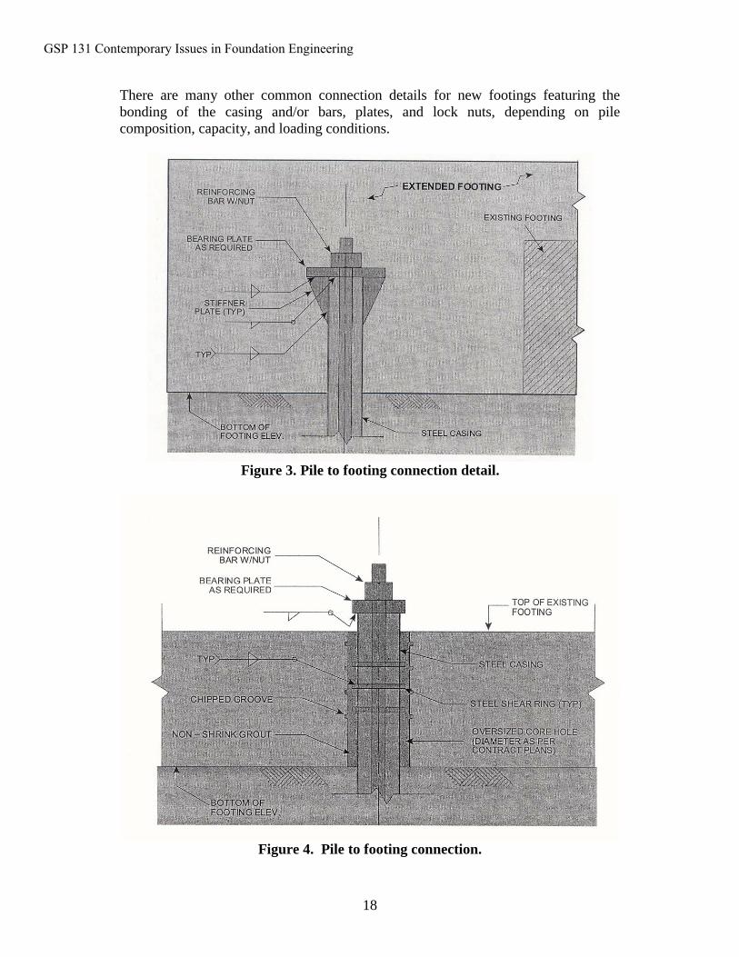
For example, Figure 3 shows a composite reinforced pile connected to a new (or extended) footing. The footing tension and compression load is transferred to the pile through the top bearing plate. The stiffener plates provide bending strength to the plate, plus provide additional weld length for transferring the load from the bearing plate to the pile casing. The stiffener plates can be eliminated if the support of the top plate and additional weld length are not required. Additional considerations for this connection detail include the following:
• The portion of the tension load carried by the reinforcing bar can be transferred to the top plate through the nut, reducing the plate-to-casing weld requirement.
• The bond between the pile casing and the footing concrete can be utilized, reducing the load capacity required for the top plate and top plate to casing weld.
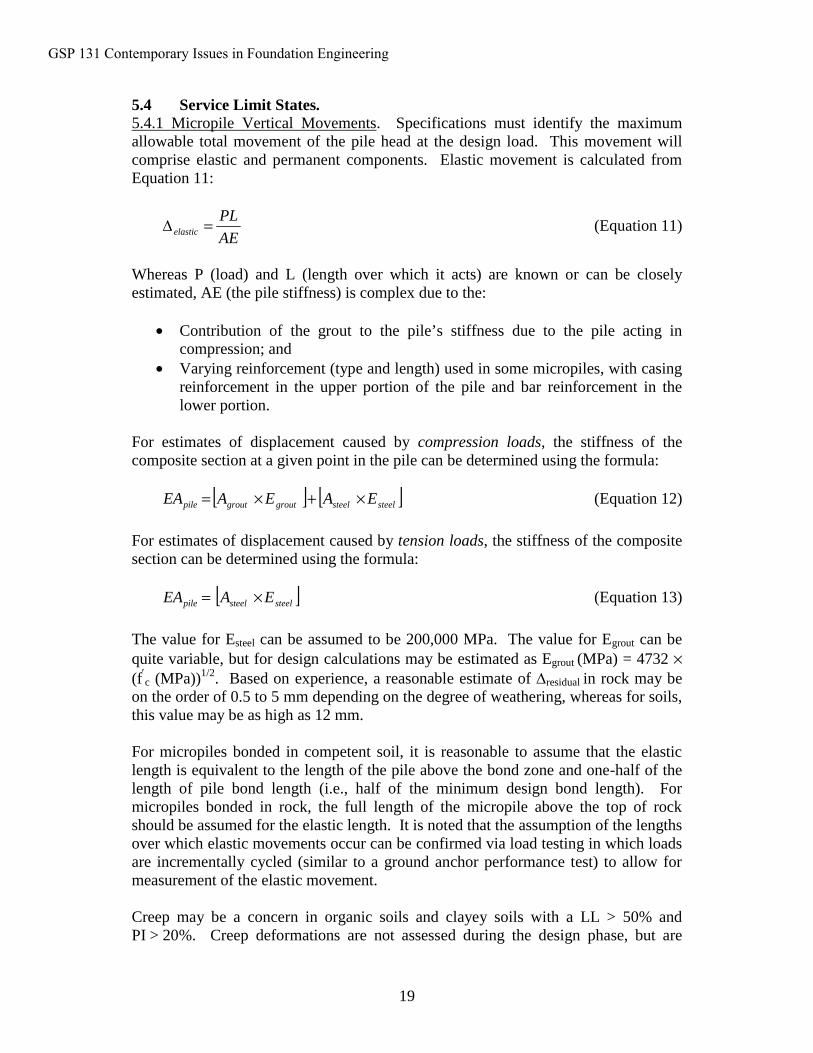
Figure 4 shows a composite reinforced pile connected to an existing footing. The pile is installed through an oversized hole cored through the existing footing or slab. After the pile is installed, the core hole is cleaned and filled with cement grout. Steel rings are welded to the top section of the casing prior to pile installation. The use of non-shrink grout may be appropriate to avoid shrinkage problems in large cored holes.
These rings transfer the pile load from the casing to the non-shrink grout. Adequate spacing must be used between the rings to avoid combining bearing stresses in the concrete and grout. The total capacity of the connection is controlled by the sum of the bearing strength of the rings, the capacity of the load transfer across the interface between the non-shrink grout and the existing concrete, and the shear capacity of the existing concrete.
Grooves may be chipped into sides of the core hole (typical dimension = 20 mm deep and 32 mm wide) to increase the load carrying capacity of the grout to existing concrete. Also, vertical reinforcing bars may be drilled and epoxied into the existing concrete around the exterior of the connection to increase the punching shear capacity.
For thick existing footings, the shear rings and grooves in Figure 4 may be eliminated. Load tests on the connections are appropriate to verify the casing to grout bond and grout to existing concrete bond for the proposed materials and methods.
GSP 131 Contemporary Issues in Foundation Engineering
18
There are many other common connection details for new footings featuring the bonding of the casing and/or bars, plates, and lock nuts, depending on pile composition, capacity, and loading conditions.
Figure 3. Pile to footing connection detail.
Figure 4. Pile to footing connection.
GSP 131 Contemporary Issues in Foundation Engineering
19
5.4 Service Limit States.5.4.1 Micropile Vertical Movements. Specifications must identify the maximum allowable total movement of the pile head at the design load. This movement will comprise elastic and permanent components. Elastic movement is calculated from Equation 11:
AE
PLelastic =∆ (Equation 11)
Whereas P (load) and L (length over which it acts) are known or can be closely estimated, AE (the pile stiffness) is complex due to the:
• Contribution of the grout to the pile’s stiffness due to the pile acting in compression; and
• Varying reinforcement (type and length) used in some micropiles, with casing reinforcement in the upper portion of the pile and bar reinforcement in the lower portion.
For estimates of displacement caused by compression loads, the stiffness of the composite section at a given point in the pile can be determined using the formula:
[ ] [ ]steelsteelgroutgroutpile EAEAEA ×+×= (Equation 12)
For estimates of displacement caused by tension loads, the stiffness of the composite section can be determined using the formula:
[ ]steelsteelpile EAEA ×= (Equation 13)
The value for Esteel can be assumed to be 200,000 MPa. The value for Egrout can be quite variable, but for design calculations may be estimated as Egrout (MPa) = 4732 ×(f′c (MPa))1/2. Based on experience, a reasonable estimate of ∆residual in rock may be on the order of 0.5 to 5 mm depending on the degree of weathering, whereas for soils, this value may be as high as 12 mm.
For micropiles bonded in competent soil, it is reasonable to assume that the elastic length is equivalent to the length of the pile above the bond zone and one-half of the length of pile bond length (i.e., half of the minimum design bond length). For micropiles bonded in rock, the full length of the micropile above the top of rock should be assumed for the elastic length. It is noted that the assumption of the lengths over which elastic movements occur can be confirmed via load testing in which loads are incrementally cycled (similar to a ground anchor performance test) to allow for measurement of the elastic movement.
Creep may be a concern in organic soils and clayey soils with a LL > 50% and PI > 20%. Creep deformations are not assessed during the design phase, but are
GSP 131 Contemporary Issues in Foundation Engineering
20
checked during creep testing as being within acceptable limits and displaying a stabilizing trend.
5.4.2 Micropile Group Settlement. Micropiles in a group can undergo additional vertical displacement as a result of consolidation of soil layers below the bottom of the micropile group. Where a single pile will transfer its load to the soil in the immediate vicinity of the pile, a pile group can distribute its load to the soil layer below the group. Consideration should be made for this group displacement when the soil below the group is cohesive in nature and subject to consolidation. The method for evaluating pile group settlements is similar to that for driven piles (see FHWA HI-97-013, 1996). Equations for one-dimensional consolidation are used.
5.5 Corrosion Protection.5.5.1 General. Protecting the metallic components of a micropile against the detrimental effects of corrosion is necessary to assure adequate long-term durability of the micropile. The degree and extent of corrosion protection is a function of loading condition, the expected service life of the micropile, the aggressiveness of the ground, the perceived importance of the structure, and consequences of failure. In all cases, it is the responsibility of the Owner to select the corrosion protection for each micropile.
The conditions promoting corrosion of micropiles include:
• Low resistivity of ground;• High concentration of chlorides or sulfides in ground or groundwater;• Too low or too high hydrogen potential (pH) of ground or groundwater;• High saturation conditions; and• Stray currents.
5.5.2 Evaluation of Soil Corrosion Potential. Tests listed in Table 5 are used to classify the corrosion potential of the ground.
Table 5. Criteria for assessing ground corrosion potential.
TEST UNITS
STRONGCORROSIONPOTENTIAL/AGGRESSIVE
MILD TO NOCORROSIONPOTENTIAL/
NON-AGGRESSIVE
ASTMSTANDARD
AASHTOTEST
METHOD
pH – < 4.5, >10 5.5 < pH < 10 G51 T 289-91
Resistivity ohm-cm <2,000 Greater than 5,000 G57 T 288-91
Sulfates ppm(1) >200 Less than 200 D516 T 290-91
Chlorides ppm >100 Less than 100 D512 T 291-91
Note: (1) ppm = parts per million.
In general, the ground is classified with a strong corrosion potential or aggressive if any one of the conditions listed in the first column of Table 5 exceeds the limits listed in the third column of the table during the service life of the micropile. In addition, buried structures immediately adjacent to the project having exhibited corrosion or
GSP 131 Contemporary Issues in Foundation Engineering
21
direct chemical attack might be an indication of strong corrosion potential. If all the conditions listed in the first column of Table 5 satisfy the conditions listed in the fourth column of Table 5, the ground is classified as non-aggressive with respect to corrosion potential.
5.5.3 Corrosion Protection Systems. Corrosion protection for the central reinforcement can be provided by physical and chemical protection or a combination of both. Most commonly used are grout, epoxy coating (minimum thickness 0.4 mm, galvanizing, or encapsulation with a sheath (PVC or HDPE of minimum thickness 1 mm)). It is not practical to protect the external surface of the drill casing, since during installation, it will be abraded by the soil around it. Section 4.5.7.4 of AASHTO (2002) includes a provision to deduct 1.6 mm from the shell thickness for the concrete filled pipe to allow for “sacrificial” steel loss. Other values may be used (Table 6). A summary of recommended systems is provided in Table 7.
Table 6. Minimum dimensions (mm) of sacrificial shell thickness as corrosion protection (after FHWA-SA-97-070).
SERVICE LIFE (YEARS)SOIL TYPE 25 50 75 100
Not Aggressive 0.25 0.60 0.70 0.80Barely Aggressive 1.00 1.60 2.00 2.50Very Aggressive 2.50 4.00 5.00 6.00
Table 7. Corrosion protection requirements for micropiles.CORROSION PROTECTION
LOADING TENSION1 COMPRESSION
GROUND AGGRESSIVE2 NON AGGRESSIVE AGGRESSIVE2 NON-AGGRESSIVE
Casing a. Do not rely on casing for load capacity
a. None required if tension load on casing is less than 20% of casing thread strength
OR b. Do not rely on
casing for load capacity
a. Min. 1.6 mm corrosion loss on outside
The Specifier may use a different corrosion loss per Table 5-12.
a. NoneThe Specifier may use different corrosion loss per Table 5-12.
Reinforcing steel
a. epoxy coating3
ORb. galvanization3
ORc. encapsulation in
plastic sheath3
ANDGrout cover4
a. bare steel5
ORb. epoxy coating3
ORc. galvanization3
ORd. encapsulation in
plastic sheath3
ANDGrout cover4
a. Grout cover4
ANDThe Specifier may desire to add other options listed for tension.
a. Grout cover4
NOTES:1. Permanent tension or temporary tension (e.g., wind, seismic, impact) on critical structures. For
temporary tension on normal structures, corrosion protection for compression may be used.
GSP 131 Contemporary Issues in Foundation Engineering
22
2. Corrosion protection must extend 15 feet below corrosive material 3. Reinforcing steel corrosion protection must extend a minimum of 5 feet into casing4. Minimum 1 inch in soil and 0.5 inch in rock. If protective coatings (epoxy, galvanization, or
encapsulation) are provided in compression, minimum cover may be 0.25 inches in soil or rock.5. Not recommended for permanent or cyclic tension loads.
5.6 Seismic Considerations.5.6.1 General. An increasingly common application of micropiles is in seismic retrofit. Current practice for seismic design of bridge foundations is provided in Division 1-A of AASHTO (2002) and these generally apply to micropiles.
Results from centrifuge and finite element studies reported as part of the FOREVER (2003) project indicate that vertical micropiles in groups do little to resist horizontal seismic deformations due to their relatively low stiffness. Under seismic loading, however, inclined micropiles were shown to have a reduced “underground” bending moment as compared to vertical micropiles, but significantly higher negative bending moment at the pile head. In current U.S. practice, the concern over excessive bending moments being mobilized during the design seismic event has resulted in some concerns on the use of inclined piles for seismic retrofit projects. As reported in Chapter 5 of the FOREVER (2003) project, the Eurocode (Eurocode EC 8, 1994) indicates that inclined piles should not be used for transmitting lateral loads to the soil, but if such piles are used, they must be safely designed to carry axial and bending loads. Proponents for the use of micropiles argue that by inclining the piles and thus creating a very stiff system, it is likely that damage that may result from an earthquake will occur within the pile cap, which can be easily fixed. This issue remains unresolved at this time in the U.S. and additional research, like that being performed under FOREVER (2003), is required.
5.6.2 Load Sharing with Existing Foundations. Applications in which micropiles are used to retrofit an existing deep foundation requires that load sharing between existing foundation elements and the micropiles be evaluated. For example, in order to design additional piles to retrofit existing pile foundations damaged by the Mw 6.9 Hyogo-ken Nanbu earthquake in Japan, the following concepts were applied according to the damage of the existing piles (Japan Public Works Research Institute (JPWRI), 2002):
• Where existing piles were damaged by the earthquake, compression loads areshared by existing piles and the micropiles, but tension, lateral, and moment loads are carried by the new micropiles.
• Where existing piles were only slightly damaged, all design loads were shared by the existing piles and the new micropiles.
For the retrofit design of an old or deteriorated foundation or for a foundation in which the original structural design details and specifications are uncertain, design seismic loads should be assumed to be carried by the micropiles only. Load sharing between existing and new foundations should only be considered if the Owner has sufficient information on the existing foundation system (i.e., as-built drawings, load
GSP 131 Contemporary Issues in Foundation Engineering
23
test results, design calculations). Where this is considered, soil-structure interaction analyses will need to be performed.
5.6.3Liquefaction. In many earthquakes where liquefaction occurs, the soil may not liquefy until the end of the earthquake. Therefore, piles in liquefied ground may still be able to rely on the vertical and lateral support of the soil in the potentially liquefied zone during the earthquake. However, due to uncertainties as to exactly when liquefaction will occur, it seems prudent to assign a reduced vertical and lateral resistance to potentially liquefiable soil surrounding a pile if the pile is expected to function as a load carrying member during and after an earthquake. Results presented by Ishihara and Cubrinovski (1998) suggest that the lateral resistance of a pile in liquefied ground is approximately 0.1 to 1.0 percent of the lateral resistance in non-liquefied ground. Therefore, if a pile foundation in potentially liquefiable soil is expected to carry lateral loads after the surrounding soil liquefies, inclined piles may be required to provide adequate lateral support. This reduction in lateral support is particularly important for relatively flexible micropiles.
Studies reported in the FOREVER (2003) project showed that vertical micropiles were not effective in reducing liquefaction. Inclined micropiles, however, were shown to limit seismically-induced soil movements (and pore pressure buildup) resulting in no liquefaction in the zone affected by the piles, whereas the free-field soil did undergo liquefaction. If inclined piles are used, the pile cap connections should be designed to sustain moment loads induced by lateral movements and the inclined piles should be designed to sustain lateral loads due to soil settlement.
Final Remarks
This paper provides a brief overview of the many and varied aspects of Case 1 micropile design. It is hoped that the teaching of the manual from which this paper is drawn will help the various code recommendations and proposals become “state of practice” and that owners and contractors alike can progress on common and acceptable ground.
REFERENCES
AASHTO (1988), “Manual on Subsurface Investigations”, American Association of State
AASHTO (2002), “Standard Specifications for Highway Bridges”, Association of State Highway and Transportation Officials Publication, Washington, D.C., ISBN: 156051-171-0.
Bjerrum, L., “Norwegian experiences with steel piles to rock,” Geotechnique, Vol. 7, pp. 73-96, 1957.
GSP 131 Contemporary Issues in Foundation Engineering
24
Brittsan, D., and Speer, D., “Pile load test results for highway 280 pile uplift test site,” 1993.
Brown, D. A., Morrison, C., and Reese, L. C. (1988), “Lateral Load Behavior of Pile Group in Sand”, ASCE Journal of Geotechnical Engineering, Vol. 114, No. 11, pp. 1261-1276.
Bruce, D.A., A.F. DiMillio, and I. Juran. (1997). “Micropiles: The State of Practice Part 1: Characteristics, Definitions, and Classifications.” Ground Improvement. Thomas Telford, Vol. 1, No. 1, January, pp. 25-35.
Cadden, A.W., Gómez, J.E., “Buckling of Micropiles - A Review of Historic Research and Recent Experiences,” ADSC-IAF Micropile Committee, 2002.
Cadden, A.W., Gómez, J.E., “Buckling of Micropiles - A Review of Historic Research and Recent Experiences,” ADSC-IAF Micropile Committee, 2002.
Federal Highway Administration (1996), “Design and Construction of Driven Pile Foundations”, Hannigan, P. J., Goble, G. G., Thendean, G., Likins, G. E., and Rausche, F., Publication No. FHWA-HI-97-013, United States Department of Transportation, December.
FHWA, Drilled and Grouted Micropiles State-of-the-Practice Review. Report No. FHWA-RD-96-016/019, United States Department of Transportation, July 1997, Four Volumes.
FHWA, Micropile Design and Construction Guidelines, Implementation Manual. Publication No. FHWA-SA-97-070, 2000.
FHWA/NHI (2001), “Manual on Subsurface Investigations”, Federal Highway Administration, Manual No. FHWA NHI-01-031, Mayne, P. W., Christopher, B. R., and DeJong, J., July.
FHWA 2002
Gómez, J.E., Cadden, A., Webster, O.C., “Micropile Foundation in Karst: Static and Dynamic Testing Variability,” Proceedings: Fifth Annual Conference on Case Histories in Geotechnical Engineering, New York, New York, April 2004.
Gouvenot, D., “Essais de Chargement et de Flambement de Pieux Aiguilles,” Annales de l’Institute Technique du Bâtiment et des Travaux Publics, Comité Français de la Mécanique des Sols et des Fondations, No. 334, December 1975.
Holloway, D. M., Moriwaki, Y. Stevens, J. B., and Perez, J-Y. (1981), “Response of a Pile Group to Combined Axial and Lateral Loading”, Proceedings of the 10th
GSP 131 Contemporary Issues in Foundation Engineering
25
International Conference on Soil Mechanics and Foundation Engineering, Boulimia Publishers, Stockholm, Vol. 2, pp. 731-734.
Lizzi, F. 1982. Static Restoration of Monuments. Sagep Publisher. Genoa. Italy.
Mascardi, C.A., “Design Criteria and Performance of Micropiles,” Symposium on Soil and Rock Improvement Techniques including Geotextiles. Reinforced Earth and Modern Piling Methods, Bangkok, paper D-3, 1982.
Mascardi, C.A., “Il Comportamento dei Micropali Sottoposti a Sforzo Assiale. Momento Flettante e Taglio,” Verlag Leeman, Zurich, 1970.
Reese, L. C., Wang, S. T., Isenhower, W. M., Arréllaga, J. A., and Hendrix, J., (2000), “Technical and User’s Manual of LPILEPLUS 4.0 Computer Program”, Ensoft Publication.
Stress Engineering Services, “7 Inch Pipe Test,” Malcolm Drilling Company, Inc., Sun Valley, CA, Available through the ADSC Technical Library, 1995.
Stress Engineering Services, “Letter report of 7" 35 lb, flush connection evaluation,” Foster Threaded Products, Houston, TX, 2003.
Wang, S. T. and Reese, L. C. (1993), “COM624P-Laterally Loaded Pile Analysis Program for the Microcomputer, Version 2.0”, Federal Highway Administration Manual, Manual No. FHWA-SA-91-048.
GSP 131 Contemporary Issues in Foundation Engineering