Embed Size (px)
Citation preview
SympoSium SerieS No. �54 © 2008 ABB engineering Services
Practical ExPEriEncE in radio FrEquEncy inducEd ignition risk assEssmEnt For comaH/dsEar comPliancE†
ian r Bradby, Senior Safety Consultant ABB engineering Services, pavilion 9, Belasis Hall Technology park, Billingham, Cleveland, TS23 4yS, uK
is your site within 30km of a radio, TV or radar transmitter? if so, radio frequency induced ignition could pose a hazard to the assets on your site.
in order to comply with the Dangerous Substance and explosive Atmosphere regulations (DSeAr), companies handling substances capable of creating explosive atmospheres are required to carry out a formal risk assessment. This must consider the extent of foreseeable explosive atmospheres within and external to the process, and ensure that suitable equipment is installed to control all potential ignition sources. one potential ignition source arises from radio-frequency radiation, often identified during the preparation/review of company ComAH safety reports.
The radio-frequency environment is becoming increasingly severe, with the prolif-eration of transmitting sources, increased transmitter powers and the exploitation of new techniques. Sources for radio-frequency transmissions include radio and televi-sion broadcasts, radio communications, mobile phone communications, radar and navigational equipment. These transmission sources can affect an area of up to 30km and have the potential to impinge on most operating sites.
electromagnetic waves produced by radio-frequency transmitters will induce elec-tric currents and voltages in any conducting structure on which they impinge. The magnitude of the induced current and voltage depends upon the combination of the shape and size of the structure, the wavelength and the strength of the transmitted signal. A spark may occur if the induced voltage and currents are sufficiently large.
The latest standard for the assessment of inadvertent ignition of flammable atmo-spheres by radio-frequency radiation, BS 6656:2002, provides detailed guidance, but currently many companies are unclear about the level of risk posed by radio-frequency induced ignition.
introductionThis paper describes the methodology and practical experiences of applying BS6656:2002 to the issue of inadvertent ignition of flammable atmospheres by radio frequency radiation.
radio frequency (rF) induced ignition is a credible, but not well recognised mecha-nism for creating a source of sparks on operating plant structures. much time, effort and expenditure is spent by companies in controlling sources of ignition, so that in the event of a release of flammable material, the potential for fire or explosion is minimised.
†© 2008 ABB engineering Services. Third parties only have access for limited use and no right to copy any further. intellectual property rights of iCheme allow them to make this paper available. ABB are acknowl-edged as the owner.
�
SympoSium SerieS No. �54 © 2008 ABB engineering Services
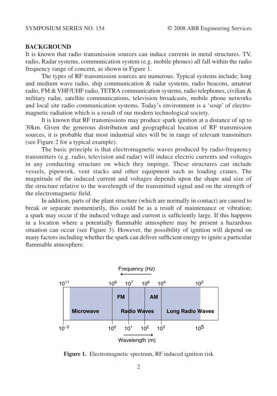
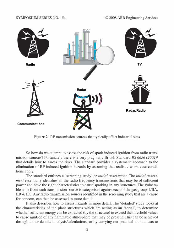
Backgroundit is known that radio transmission sources can induce currents in metal structures. TV, radio, radar systems, communication system (e.g. mobile phones) all fall within the radio frequency range of concern, as shown in Figure �.
The types of rF transmission sources are numerous. Typical systems include; long and medium wave radio, ship communication & radar systems, radio beacons, amateur radio, Fm & VHF/uHF radio, TeTrA communication systems, radio telephones, civilian & military radar, satellite communications, television broadcasts, mobile phone networks and local site radio communication systems. Today’s environment is a ‘soup’ of electro-magnetic radiation which is a result of our modern technological society.
it is known that rF transmissions may produce spark ignition at a distance of up to 30km. Given the generous distribution and geographical location of rF transmission sources, it is probable that most industrial sites will be in range of relevant transmitters (see Figure 2 for a typical example).
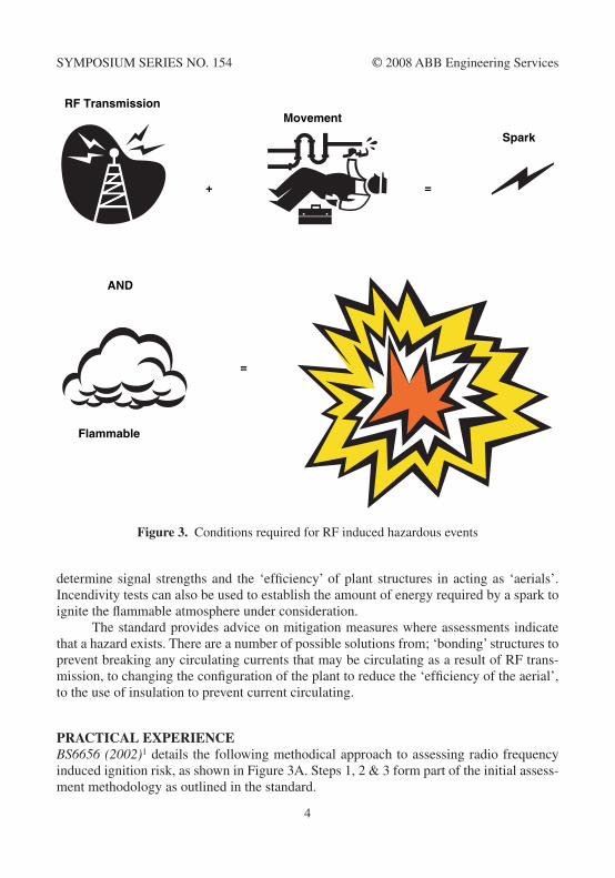
The basic principle is that electromagnetic waves produced by radio-frequency transmitters (e.g. radio, television and radar) will induce electric currents and voltages in any conducting structure on which they impinge. These structures can include vessels, pipework, vent stacks and other equipment such as loading cranes. The magnitude of the induced current and voltages depends upon the shape and size of the structure relative to the wavelength of the transmitted signal and on the strength of the electromagnetic field.
in addition, parts of the plant structure (which are normally in contact) are caused to break or separate momentarily, this could be as a result of maintenance or vibration; a spark may occur if the induced voltage and current is sufficiently large. if this happens in a location where a potentially flammable atmosphere may be present a hazardous situation can occur (see Figure 3). However, the possibility of ignition will depend on many factors including whether the spark can deliver sufficient energy to ignite a particular flammable atmosphere.
103 105102
102
101
1011 108 107 106 104
10010–3
Frequency (Hz)
Wavelength (m)
Long Radio WavesRadio WavesMicrowave
AMFM
Figure 1. electromagnetic spectrum, rF induced ignition risk
2
SympoSium SerieS No. �54 © 2008 ABB engineering Services
So how do we attempt to assess the risk of spark induced ignition from radio trans-mission sources? Fortunately there is a very pragmatic British Standard BS 6656 (2002)� that details how to assess the risks. The standard provides a systematic approach to the elimination of rF induced ignition hazards by assuming that realistic worst case condi-tions apply.
The standard outlines a ‘screening study’ or initial assessment. The initial assess-ment essentially identifies all the radio frequency transmissions that may be of sufficient power and have the right characteristics to cause sparking in any structures. The vulnera-ble zone from each transmission source is categorised against each of the gas groups i/iiA, iiB & iiC. Any radio transmission sources identified in the screening study that are a cause for concern, can then be assessed in more detail.
it also describes how to assess hazards in more detail. The ‘detailed’ study looks at the characteristics of the plant structures which are acting as an ‘aerial’, to determine whether sufficient energy can be extracted (by the structure) to exceed the threshold values to cause ignition of any flammable atmosphere that may be present. This can be achieved through either detailed analysis/calculations, or by carrying out practical on site tests to
Radar/Radio
TVRadio
Radar
Communications
Figure 2. rF transmission sources that typically affect industrial sites
3
SympoSium SerieS No. �54 © 2008 ABB engineering Services
determine signal strengths and the ‘efficiency’ of plant structures in acting as ‘aerials’. incendivity tests can also be used to establish the amount of energy required by a spark to ignite the flammable atmosphere under consideration.
The standard provides advice on mitigation measures where assessments indicate that a hazard exists. There are a number of possible solutions from; ‘bonding’ structures to prevent breaking any circulating currents that may be circulating as a result of rF trans-mission, to changing the configuration of the plant to reduce the ‘efficiency of the aerial’, to the use of insulation to prevent current circulating.
Practical ExPEriEncEBS6656 (2002)� details the following methodical approach to assessing radio frequency induced ignition risk, as shown in Figure 3A. Steps �, 2 & 3 form part of the initial assess-ment methodology as outlined in the standard.
MovementRF Transmission
Flammable
=+
Spark
AND
=
Figure 3. Conditions required for rF induced hazardous events
4
SympoSium SerieS No. �54 © 2008 ABB engineering Services
The following example is used to illustrate some of the issues involved in addressing radio frequency induced ignition risk from a practical point of view.
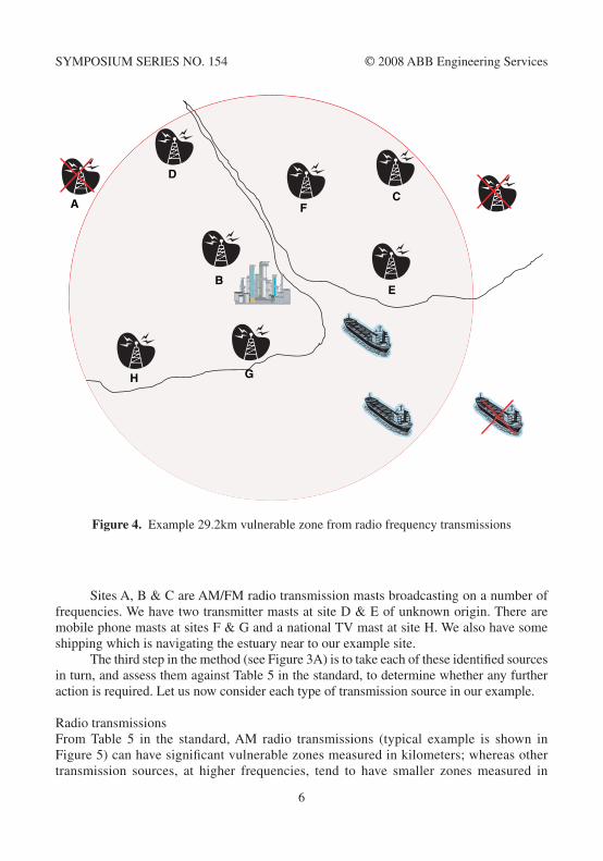
iNiTiAl ASSeSSmeNTThis simplified example describes a typical approach using the Initial assessment as outlined in section �0.2.2 of the standard. The Initial assessment is designed to eliminate from further consideration those locations from which it is highly unlikely that a hazard exists. it is based on realistic worst-case estimates of the radius of the zone around differ-ent classes of transmitter; therefore Table 5 in the standard has been used in preference to Table 6. (Tables 5 & 6 consider the effects of electromagnetic fields on differing plant geometries.) The initial screening is also based on gas group iiC (Hydrogen as the repre-sentative gas) as the flammable atmosphere, which again represents the worst-case scenario.
The first step (see item � in Figure 3A) is to determine the maximum vulnerable zone. This is taken from Table 7 in the standard, and in our example is 29.2 km which is based on gas group iiC. The extent of this zone is shown in Figure 4. Any transmission sources outside this zone do not require any further consideration and can be eliminated from the study.
The second step in our method (see Figure 3A) is to identify all the significant trans-mission sources within the vulnerable zone. The standard considers transmission sources operating in the 9 kHz to 60 GHz range as these present a potential ignition risk. in our example, these have been identified as shown in Figure 4.
1. Determine the size of maximumvulnerable zone
2. Identify significant transmissionsources within vulnerable zone
3. Screen each type of transmissionsource using table 5 in BS6656
4. Apply the full assessmentmethodology for remaining sources Full Assessment
Initial Assessment
Figure 3a. BS6656 Assessment methodology
5
SympoSium SerieS No. �54 © 2008 ABB engineering Services
Sites A, B & C are Am/Fm radio transmission masts broadcasting on a number of frequencies. We have two transmitter masts at site D & e of unknown origin. There are mobile phone masts at sites F & G and a national TV mast at site H. We also have some shipping which is navigating the estuary near to our example site.
The third step in the method (see Figure 3A) is to take each of these identified sources in turn, and assess them against Table 5 in the standard, to determine whether any further action is required. let us now consider each type of transmission source in our example.
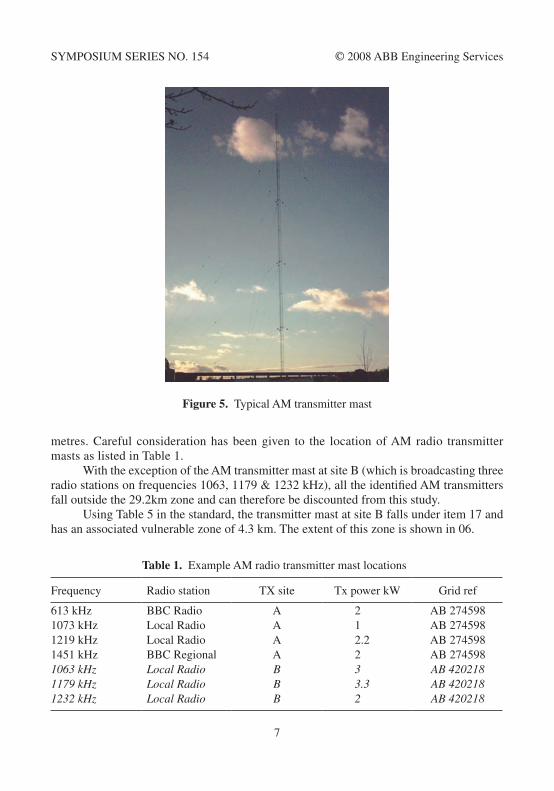
radio transmissionsFrom Table 5 in the standard, Am radio transmissions (typical example is shown in Figure 5) can have significant vulnerable zones measured in kilometers; whereas other transmission sources, at higher frequencies, tend to have smaller zones measured in
A
B
C
D
E
F
H G
Figure 4. example 29.2km vulnerable zone from radio frequency transmissions
6
SympoSium SerieS No. �54 © 2008 ABB engineering Services
metres. Careful consideration has been given to the location of Am radio transmitter masts as listed in Table �.
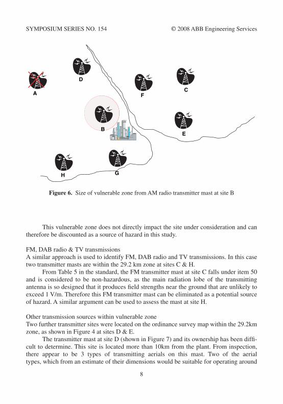
With the exception of the Am transmitter mast at site B (which is broadcasting three radio stations on frequencies �063, ��79 & �232 kHz), all the identified Am transmitters fall outside the 29.2km zone and can therefore be discounted from this study.
using Table 5 in the standard, the transmitter mast at site B falls under item �7 and has an associated vulnerable zone of 4.3 km. The extent of this zone is shown in 06.
Figure 5. Typical Am transmitter mast
table 1. example Am radio transmitter mast locations
Frequency radio station TX site Tx power kW Grid ref
6�3 kHz BBC radio A 2 AB 274598�073 kHz local radio A � AB 274598�2�9 kHz local radio A 2.2 AB 274598�45� kHz BBC regional A 2 AB 2745981063 kHz Local Radio B 3 AB 4202181179 kHz Local Radio B 3.3 AB 4202181232 kHz Local Radio B 2 AB 420218
7
SympoSium SerieS No. �54 © 2008 ABB engineering Services
This vulnerable zone does not directly impact the site under consideration and can therefore be discounted as a source of hazard in this study.
Fm, DAB radio & TV transmissionsA similar approach is used to identify Fm, DAB radio and TV transmissions. in this case two transmitter masts are within the 29.2 km zone at sites C & H.
From Table 5 in the standard, the Fm transmitter mast at site C falls under item 50 and is considered to be non-hazardous, as the main radiation lobe of the transmitting antenna is so designed that it produces field strengths near the ground that are unlikely to exceed � V/m. Therefore this Fm transmitter mast can be eliminated as a potential source of hazard. A similar argument can be used to assess the mast at site H.
other transmission sources within vulnerable zoneTwo further transmitter sites were located on the ordinance survey map within the 29.2km zone, as shown in Figure 4 at sites D & e.
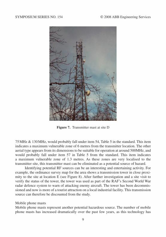
The transmitter mast at site D (shown in Figure 7) and its ownership has been diffi-cult to determine. This site is located more than �0km from the plant. From inspection, there appear to be 3 types of transmitting aerials on this mast. Two of the aerial types, which from an estimate of their dimensions would be suitable for operating around
A
B
C
D
E
F
H G
Figure 6. Size of vulnerable zone from Am radio transmitter mast at site B
8
SympoSium SerieS No. �54 © 2008 ABB engineering Services
75 mHz & �30 mHz, would probably fall under item 54, Table 5 in the standard. This item indicates a maximum vulnerable zone of 6 metres from the transmitter location. The other aerial type appears from its dimensions to be suitable for operation at around 500mHz, and would probably fall under item 57 in Table 5 from the standard. This item indicates a maximum vulnerable zone of �.3 metres. As these zones are very localised to the transmitter site, this transmitter mast can be eliminated as a potential source of hazard.
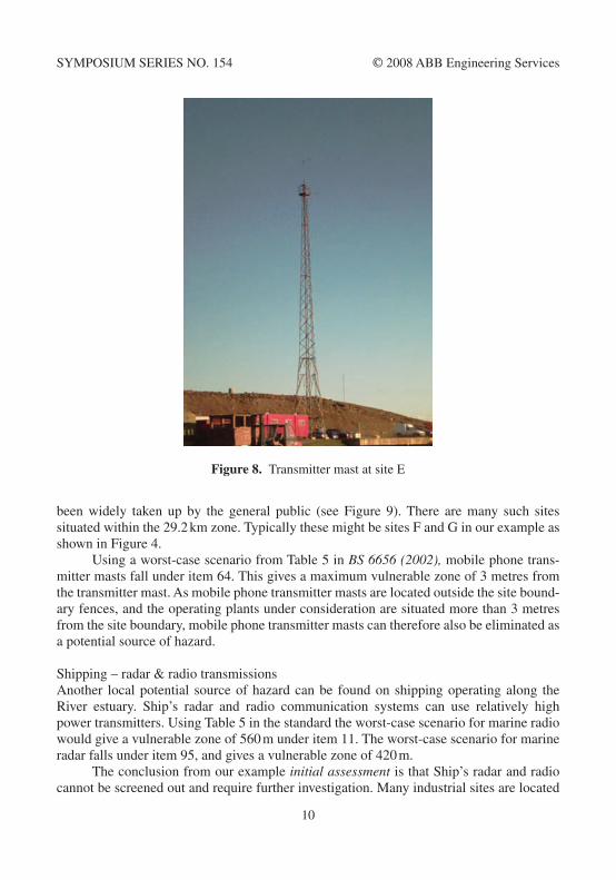
identifying potential rF sources can be an interesting and entertaining activity. For example, the ordinance survey map for the area shows a transmission tower in close proxi-mity to the site at location e (see Figure 8). After further investigation and a site visit to verify the status of the tower, the tower was used as part of the rAF’s Second World War radar defence system to warn of attacking enemy aircraft. The tower has been decommis-sioned and now is more of a tourist attraction on a local industrial facility. This transmission source can therefore be discounted from the study.
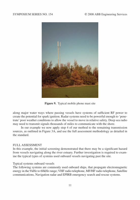
mobile phone mastsmobile phone masts represent another potential hazardous source. The number of mobile phone masts has increased dramatically over the past few years, as this technology has
Figure 7. Transmitter mast at site D
9
SympoSium SerieS No. �54 © 2008 ABB engineering Services
been widely taken up by the general public (see Figure 9). There are many such sites situated within the 29.2 km zone. Typically these might be sites F and G in our example as shown in Figure 4.
using a worst-case scenario from Table 5 in BS 6656 (2002), mobile phone trans-mitter masts fall under item 64. This gives a maximum vulnerable zone of 3 metres from the transmitter mast. As mobile phone transmitter masts are located outside the site bound-ary fences, and the operating plants under consideration are situated more than 3 metres from the site boundary, mobile phone transmitter masts can therefore also be eliminated as a potential source of hazard.
Shipping – radar & radio transmissionsAnother local potential source of hazard can be found on shipping operating along the river estuary. Ship’s radar and radio communication systems can use relatively high power transmitters. using Table 5 in the standard the worst-case scenario for marine radio would give a vulnerable zone of 560 m under item ��. The worst-case scenario for marine radar falls under item 95, and gives a vulnerable zone of 420 m.
The conclusion from our example initial assessment is that Ship’s radar and radio cannot be screened out and require further investigation. many industrial sites are located
Figure 8. Transmitter mast at site e
�0
SympoSium SerieS No. �54 © 2008 ABB engineering Services
along major water ways where passing vessels have systems of sufficient rF power to create the potential for spark ignition. radar systems need to be powerful enough to ‘pene-trate’ poor weather conditions to allow the vessel to move in relative safety. Deep sea radio may need to transmit signals thousands of miles to communicate with the shore.
in our example we now apply step 4 of our method to the remaining transmission sources, as outlined in Figure 3A, and use the full assessment methodology as detailed in the standard.
Full ASSeSSmeNTin this example, the initial screening demonstrated that there may be a significant hazard from vessels navigating along the river estuary. Further investigation is required to exam-ine the typical types of systems used onboard vessels navigating past the site.
Typical systems onboard vessels The following systems are commonly used onboard ships, that propagate electromagnetic energy in the 9 kHz to 60kHz range; VHF radio telephone, mF/HF radio telephone, Satellite communications, Navigation radar and epirB emergency search and rescue systems.
Figure 9. Typical mobile phone mast site
��
SympoSium SerieS No. �54 © 2008 ABB engineering Services
VHF radio telephoneVHF radio is the primary means of voice communication between the ship and shore, capable of operating at a range of up to 50kms. When a vessel is being piloted to its berth, VHF radio is the system that is used to communicate with the Harbour office. VHF marine radio operates from �50 mhz to �65 mHz, with typical transmitter powers of 25 watts. When in port, these systems are required to operate on reduced power, typically around � watt, which reduces further any potential radio-frequency induced spark ignition risk. VHF radio remains operational at all times. Vessels also have independent additional VHF radio system(s) available in the event of a main VHF radio system failure.
Satellite communicationsSatellite communication systems are used to provide computer-to-computer links for internet, e-mail and other business systems. The satellite phone system also provides voice communications when the vessel is out of VHF radio range. Typical systems operate at �.6 GHz with power ratings of around �50 watts. These systems operate continuously.
mF/HF radio telephonemF/HF marine radio is essentially an independent backup communication system used to communicate with the shore. it is capable of operating over thousands of kilometres in the �.6 mHz to 30 mHz range, with typical transmitter powers of around 400 watts. Current practice is for this system to remain in ‘standby mode’ until the vessel has docked. on docking, the antennae is switched to an ‘earthed’ position, to prevent any inadvertent trans-missions. This is carried out by operating a switching device on the radio set. There are no recognized circumstances, other than planned maintenance, when the mF/HF radio system would be required in port.
epirBelectric position indicating radio Beacons are small self-contained, battery operated, low power systems used to assist in the location of survivors in search and rescue opera-tions. These operate in the mHz frequency range with transmitter powers measured in milliwatts.
Navigation radarTypically there are two independent radar systems on vessels; S-band and X-band.
X-band operates at �0 GHz with typical transmitter powers up to 50 kW and gives higher resolution than S-band. This is the system that is used by the Harbour master’s office to track ship movements. S-band operates at 3 GHz with typical transmitter powers up to 60 kW and can provide better definition in poor weather conditions e.g. ability to ‘see through rain’. Both these systems are required to bring a vessel safely into port, and are actively used in poor visibility conditions. The radar systems are switched off once the vessel has safely docked.
�2
SympoSium SerieS No. �54 © 2008 ABB engineering Services
ANAlySiS oF SySTemS oNBoArD SHippiNGThe geographical layout of the antennae relative to the shore, when the vessel is docked, is considered here as part of this example analysis.
Typical ship’s beam again can vary considerably, however the smallest vessels have a beam of approximately �2 m. radar and radio antennae are located on the highest points of vessels to eliminate potential ‘blind spots’ in communication. The lowest estimated antennae position would be at least �0 m above the deck.
Jetty loading arms are considered to be the most vulnerable pieces of land-based equipment to hazard sources from the ship, during unloading operations. They have the correct geometry to form an antenna capable of converting any received em radiation into potential spark energy. However, due to concerns over static discharges when a ship is unloading at the jetty, loading arms incorporate an isolator and so cannot form a receiving loop with the ship. Jetty loading arms can therefore be discounted from the analysis.
VHF rADio TelepHoNeVHF radio is the primary means of voice communication between the ship and shore. VHF radio Telephone falls under item 54 in Table 5 in the standard. in this example, if we take gas group iiB as the most demanding case for all the jetties, then this gives a maximum hazard range of 4.5 m. Taking the typical dimensions of the smallest 65 m vessel that docks by the site, then this hazard range is within the confines of the ship, and would not impact on shore operations (see Figure �0). Therefore VHF radio telephone can be discounted from this analysis. When in port, these VHF systems are also switched to operate on reduced power, typically around � watt, which would further reduce any spark ignition risk.
Satellite communicationsSatellite communication systems are used to provide computer-to-computer links and operate continuously. Taking a conservative approach, Satellite Communications would fall under item �08 in Table 5, with an associated hazard zone of 4.5 m for gas group iiB. From Figure �0, this hazard range is within the confines of the ship and would not impact on shore operations. Therefore Satellite Communications can be discounted from this analysis as a source of hazard.
mF/HF radio telephonemF/HF marine radio provides essentially an independent backup communication system that would not be used in port. Taking a conservative approach, mF/HF radio telephone falls under item 23 in table 5 in the standard. This would give a maximum hazardous range of up to 450 m for any shipping traffic navigating along the estuary either past the site or to the jetties. This could have a significant impact on site operations.
mF/HF marine radio is essentially a backup communications system for deep-sea operation, which is not required in port. The mF/HF marine radio is independent, and separate from, the VHF radio system used to communicate with the Harbour master’s
�3
SympoSium SerieS No. �54 © 2008 ABB engineering Services
office in port. The mF/HF radio is in a ‘standby mode’ and does present any hazard other than accidental operation. Communication with the Harbour Authorities is via VHF chan-nels, and so accidental operation is considered unlikely. When in port, these mF/HF systems are switched to an ‘earthed’ position, which eliminates any spark ignition risk. Additional procedural measures could be considered to further reduce the possibility of accidental operation while vessels are navigating along the estuary.
epirBelectric position indicating radio Beacons are small self-contained, battery operated, low power systems used to assist in the location of survivors in search and rescue operations. Therefore epirB can be discounted as a hazards source from this analysis.
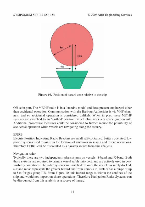
Navigation radarTypically there are two independent radar systems on vessels; S-band and X-band. Both these systems are required to bring a vessel safely into port, and are actively used in poor visibility conditions. The radar systems are switched off once the vessel has safely docked. S-Band radar represents the greater hazard and from item 93 in Table 5 has a range of up to 8 m for gas group iiB. From Figure �0, this hazard range is within the confines of the ship and would not impact on shore operations. Therefore Navigation radar Systems can be discounted from this analysis as a source of hazard.
Figure 10. position of hazard zone relative to the ship
�4
SympoSium SerieS No. �54 © 2008 ABB engineering Services
conclusionsThe conclusions from the full assessment example may be that rF transmissions from shipping could impinge on the site. Although this source of radio frequency energy repre-sents a potential source of ignition, it must be recognised that safeguards may already in place on site that prevent the creation of flammable atmospheres and sparks, i.e. plant integrity, ATeX area classification measures and equipment earthing. Hence, the risk of a flammable atmosphere being present, co-incident with an ignition source due to radio frequency effects is small. As the risk of an explosion due to radio frequency induced igni-tion is small, then cost benefit analysis indicates that significant expenditure on further risk reduction measures could be grossly disproportionate. Hence, only low cost risk reduction measures should be considered. For example, mF/HF marine radio is essentially a ‘backup’ communications system intended for deep-sea operation, which is not required, or used in port. The mF/HF marine radio system is independent, and separate from, the VHF radio system used to communicate with the Harbour master’s office. in port, mF/HF marine radio is in a ‘standby mode’, and does not present any hazard other than through accidental operation. Additional procedural measures could be considered to further reduce the possi-bility of accidental operation, while vessels are navigating along the estuary.
This paper has described in detail examples of initial and full assessments, in accor-dance with the guidance in BS 6656 (2002). The assessment of the risk from rF induced ignition will be dependent on the location of rF sources in relation to the site under consid-eration. each assessment will need to be tailored to the needs of the site. long wave radio, radar and shipping represent the highest level of risk of rF induced ignition.
many industrial sites are located along major water ways where passing vessels have systems of sufficient rF power to create the potential for spark ignition. radar systems need to be powerful enough to ‘penetrate’ poor weather conditions to allow the vessel to move in relative safety. Deep sea radio may need to transmit signals thousands of miles to communicate with the shore.
rEFErEncE“BS 6656:2002 Assessment of inadvertent ignition of flammable atmospheres by radio-
frequency radiation – Guide” – 30th october 2002 - iSBN 0 580 40595 8
�5