Embed Size (px)
Citation preview
1
SEMICON® Japan 2006
Pre and Post SEMI F47 Compliance Issues
Mark Stephens, P.E.Engineering Manager
Semiconductor & Industrial PQ ServicesEPRI
942 Corridor Park BlvdKnoxville, TN 37932W:+001.865.218.8022M: [email protected]
2
SEMICON® Japan 2006
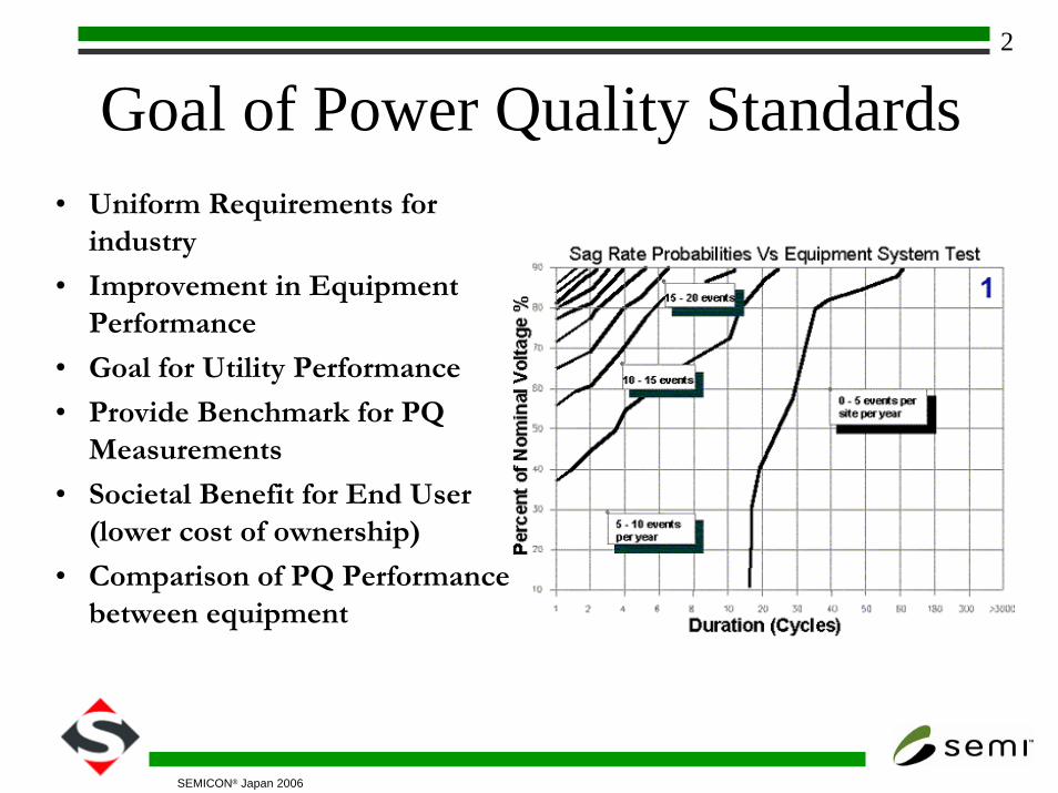
Goal of Power Quality Standards• Uniform Requirements for
industry
• Improvement in Equipment Performance
• Goal for Utility Performance
• Provide Benchmark for PQ Measurements
• Societal Benefit for End User (lower cost of ownership)
• Comparison of PQ Performance between equipment
3
SEMICON® Japan 2006
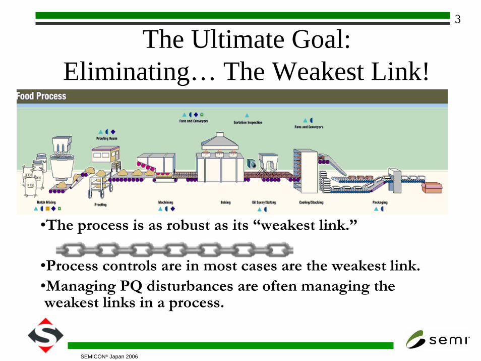
The Ultimate Goal: Eliminating… The Weakest Link!
•The process is as robust as its “weakest link.”
•Process controls are in most cases are the weakest link. •Managing PQ disturbances are often managing theweakest links in a process.
4
SEMICON® Japan 2006
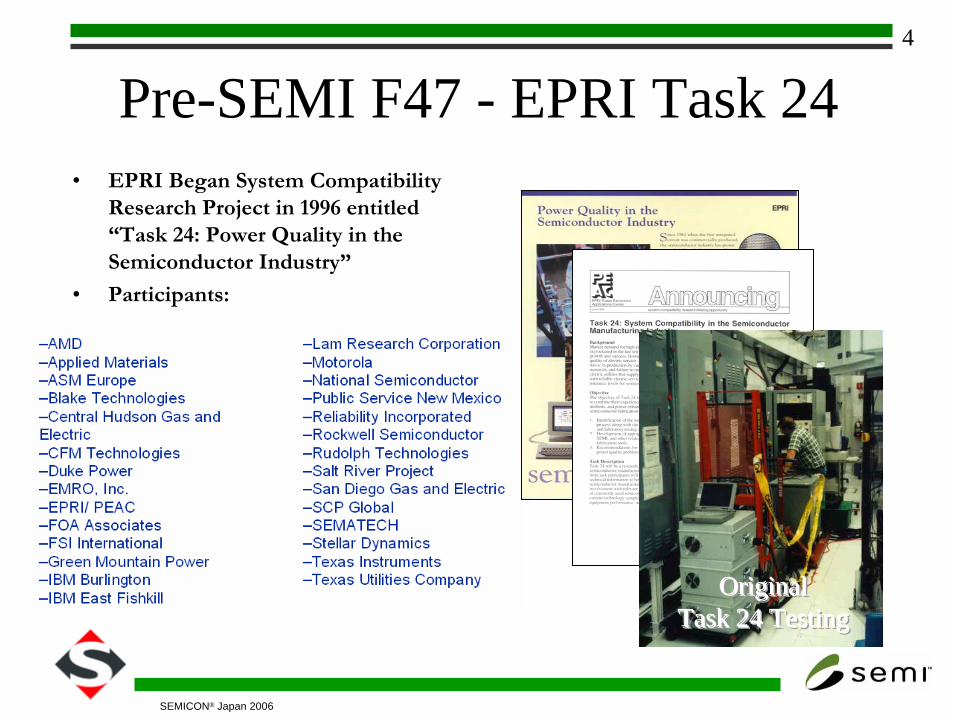
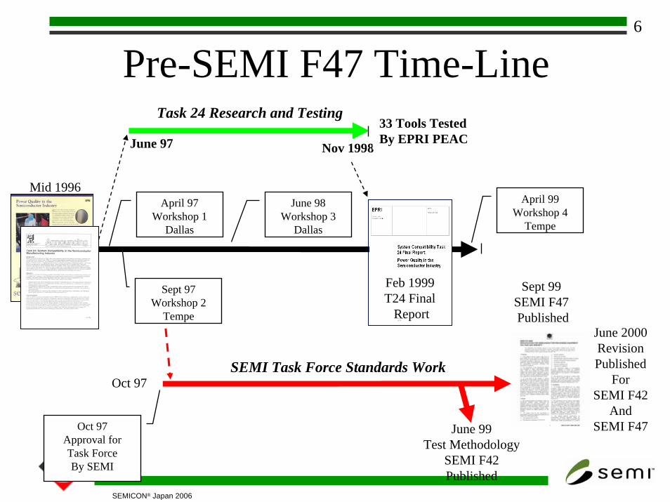
Pre-SEMI F47 - EPRI Task 24• EPRI Began System Compatibility
Research Project in 1996 entitled “Task 24: Power Quality in the Semiconductor Industry”
• Participants:
OriginalOriginalOriginalTask 24 TestingTask 24 TestingTask 24 Testing
5
SEMICON® Japan 2006
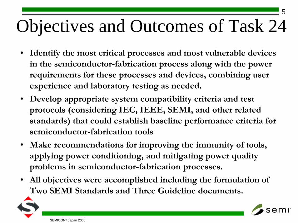
Objectives and Outcomes of Task 24• Identify the most critical processes and most vulnerable devices
in the semiconductor-fabrication process along with the power requirements for these processes and devices, combining user experience and laboratory testing as needed.
• Develop appropriate system compatibility criteria and test protocols (considering IEC, IEEE, SEMI, and other related standards) that could establish baseline performance criteria for semiconductor-fabrication tools
• Make recommendations for improving the immunity of tools, applying power conditioning, and mitigating power quality problems in semiconductor-fabrication processes.
• All objectives were accomplished including the formulation of Two SEMI Standards and Three Guideline documents.
6
SEMICON® Japan 2006
Pre-SEMI F47 Time-Line
Mid 1996
Feb 1999T24 Final
Report
April 97Workshop 1
Dallas
Sept 97Workshop 2
Tempe
June 98Workshop 3
Dallas
April 99Workshop 4
Tempe
June 97
Task 24 Research and Testing
Nov 1998
33 Tools TestedBy EPRI PEAC
Oct 97
Oct 97Approval forTask Force By SEMI
Sept 99SEMI F47Published
June 2000RevisionPublished
ForSEMI F42
AndSEMI F47June 99
Test MethodologySEMI F42Published
SEMI Task Force Standards Work
7
SEMICON® Japan 2006
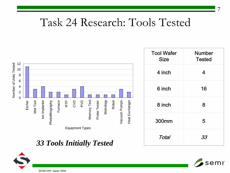
Task 24 Research: Tools Tested
Tool Wafer Size
Number Tested
4 inch 4
6 inch 16
8 inch 8
300mm 5
Total 33
0
24
6
810
12
Etc
her
Wet
Too
l
Ion
Impl
ante
r
Phot
olith
ogra
phy
Furn
ace
RTP
CV
D
PV
D
Mem
ory
Test
Pro
be T
este
r
Met
rolo
gy
Rob
ot
Vacu
um P
umps
Hea
t Exc
hang
erEquipment Types
Num
ber o
f Uni
ts T
este
d
33 Tools Initially Tested
8
SEMICON® Japan 2006
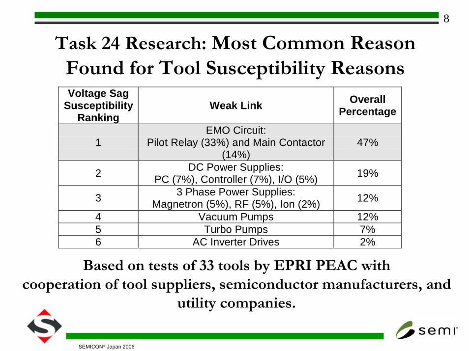
Task 24 Research: Most Common Reason Found for Tool Susceptibility ReasonsVoltage Sag
Susceptibility Ranking
Weak Link Overall Percentage
1 EMO Circuit:
Pilot Relay (33%) and Main Contactor (14%)
47%
2 DC Power Supplies: PC (7%), Controller (7%), I/O (5%) 19%
3 3 Phase Power Supplies: Magnetron (5%), RF (5%), Ion (2%) 12%
4 Vacuum Pumps 12% 5 Turbo Pumps 7% 6 AC Inverter Drives 2%
Based on tests of 33 tools by EPRI PEAC with
cooperation of tool suppliers, semiconductor manufacturers, and utility companies.
9
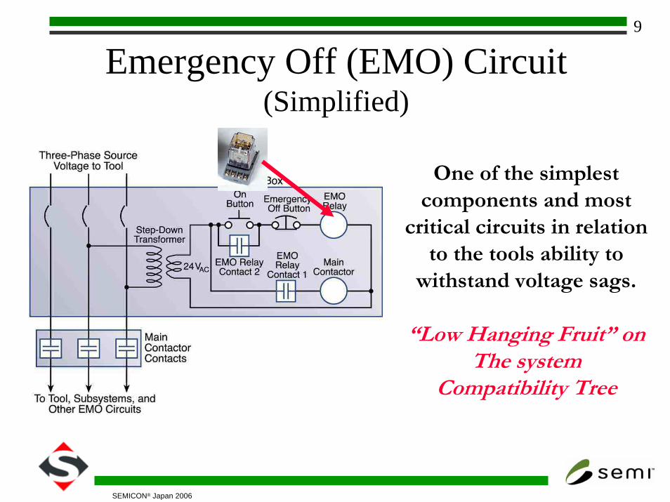
SEMICON® Japan 2006
Emergency Off (EMO) Circuit(Simplified)
One of the simplest components and most
critical circuits in relation to the tools ability to
withstand voltage sags.
“Low Hanging Fruit” onThe system
Compatibility Tree
10
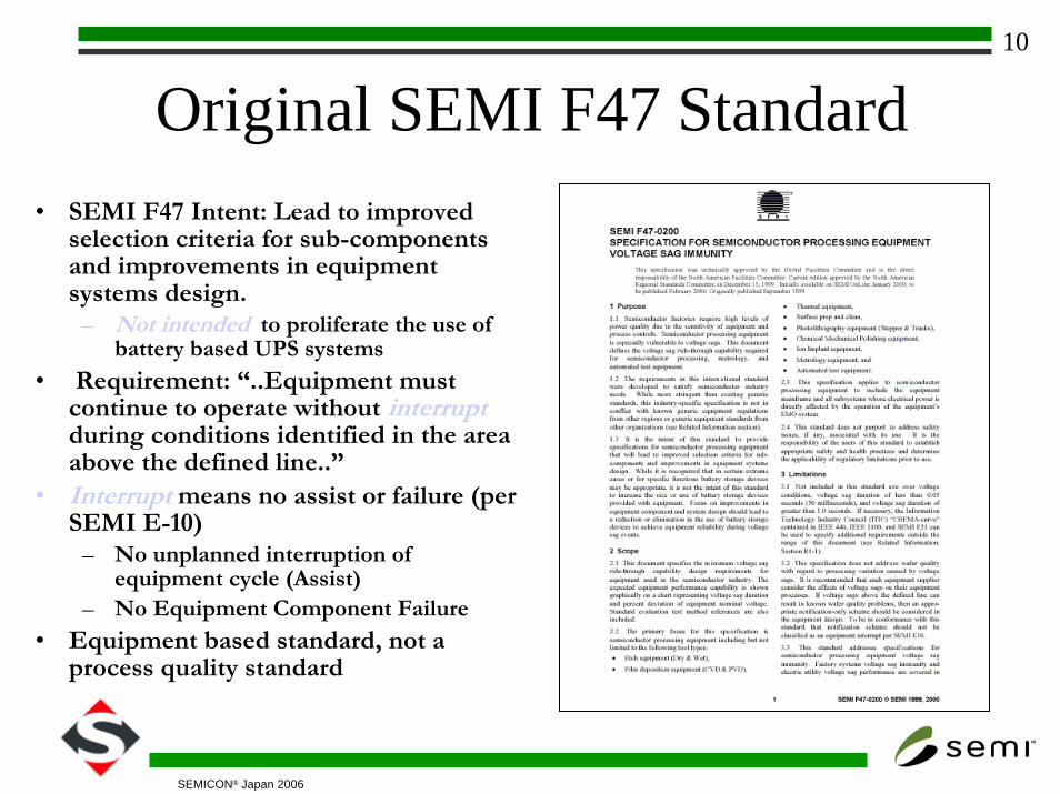
SEMICON® Japan 2006
Original SEMI F47 Standard• SEMI F47 Intent: Lead to improved
selection criteria for sub-components and improvements in equipment systems design.
– Not intended to proliferate the use of battery based UPS systems
• Requirement: “..Equipment must continue to operate without interruptduring conditions identified in the area above the defined line..”
• Interrupt means no assist or failure (per SEMI E-10)
– No unplanned interruption of equipment cycle (Assist)
– No Equipment Component Failure
• Equipment based standard, not a process quality standard
11
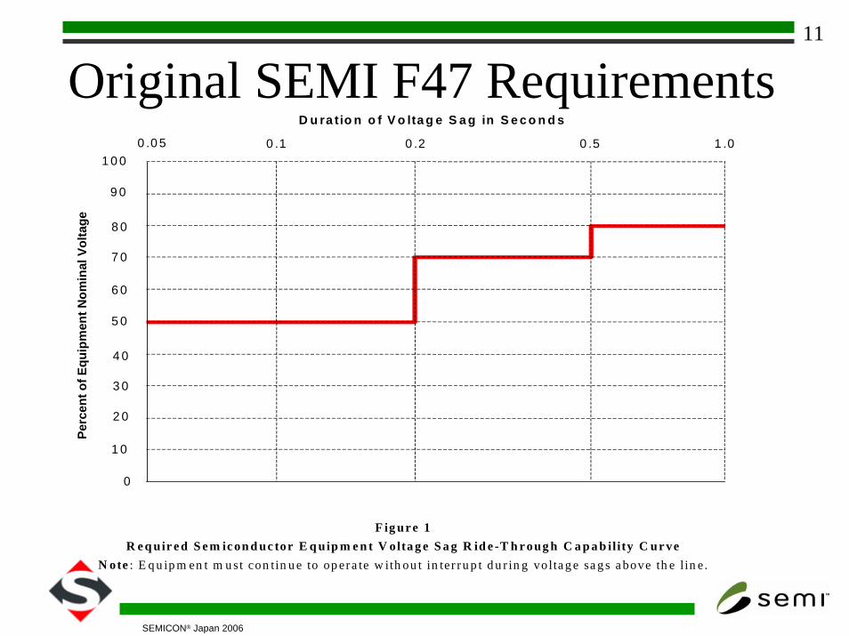
SEMICON® Japan 2006
Original SEMI F47 RequirementsPe
rcen
t of E
quip
men
t Nom
inal
Vol
tage
0 .2 0 .50 .1 1 .00 .0 5
D u ra tio n o f V o lta g e S a g in S e c o n d s
1 0 0
9 0
8 0
7 0
6 0
5 0
4 0
3 0
2 0
1 0
0
F ig ur e 1R e q uir e d S e m ic on d uc tor E q uip m e n t V olta g e S a g R id e -T h r oug h C a p a b ility C ur ve
N ote : E q u ip m en t m u st con tin u e to op era te w ith ou t in ter ru p t d u r in g volta g e sa g s a bove th e lin e .
12
SEMICON® Japan 2006
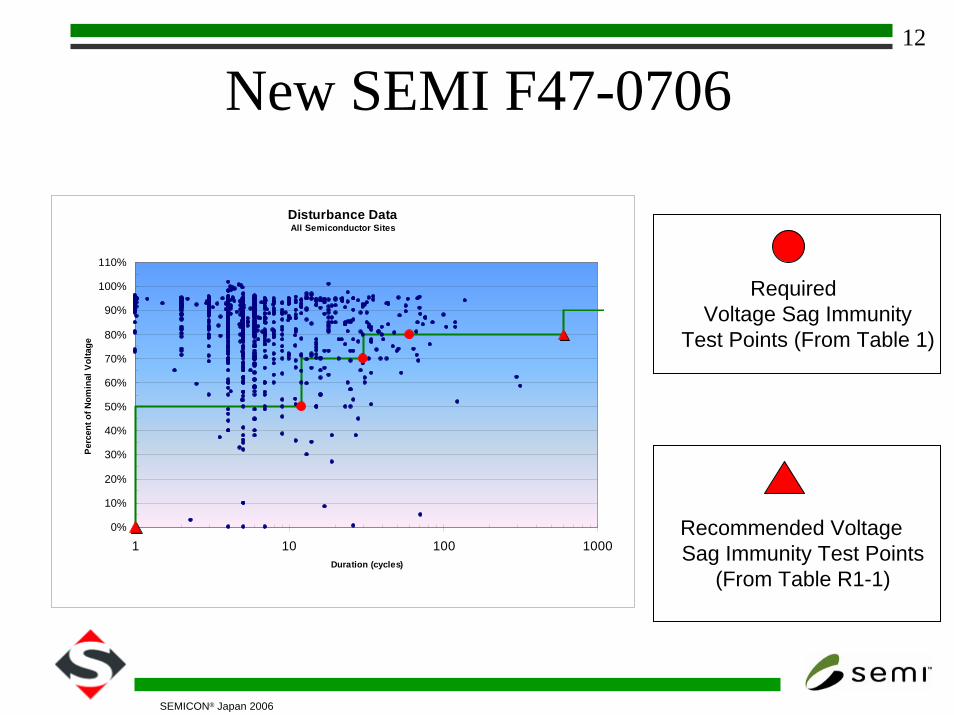
New SEMI F47-0706
Disturbance DataAll Semiconductor Sites
0%
10%
20%
30%
40%
50%
60%
70%
80%
90%
100%
110%
1 10 100 1000Duration (cycles)
Perc
ent o
f Nom
inal
Vol
tage
Required Voltage Sag Immunity
Test Points (From Table 1)
Recommended VoltageSag Immunity Test Points
(From Table R1-1)
13
SEMICON® Japan 2006
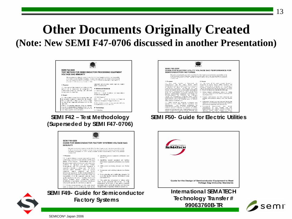
Other Documents Originally Created(Note: New SEMI F47-0706 discussed in another Presentation)
SEMI F42 – Test Methodology(Superseded by SEMI F47-0706)
SEMI F49- Guide for Semiconductor Factory Systems
SEMI F50- Guide for Electric Utilities
International SEMATECHTechnology Transfer #
99063760B-TR
14
SEMICON® Japan 2006
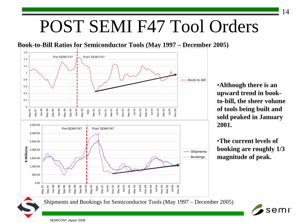
POST SEMI F47 Tool OrdersBook-to-Bill Ratios for Semiconductor Tools (May 1997 – December 2005)
Shipments and Bookings for Semiconductor Tools (May 1997 – December 2005)
•Although there is an upward trend in book-to-bill, the sheer volume of tools being built and sold peaked in January 2001.
•The current levels of booking are roughly 1/3 magnitude of peak.
0
0.2
0.4
0.6
0.8
1
1.2
1.4
1.6
May
-97
Sep-
97
Jan-
98
May
-98
Sep-
98
Jan-
99
May
-99
Sep-
99
Jan-
00
May
-00
Sept
.
Mar
-01
Jul-0
1
Nov
-01
Mar
-02
Jul-0
2
Nov
-02
Mar
-03
Jul-0
3
Nov
-03
Mar
-04
Jul-0
4
Nov
-04
Mar
-05
Jul-0
5
Nov
-05
Book-to-Bill
Pre-SEMI F47 Post SEMI F47
0.00
500.00
1,000.00
1,500.00
2,000.00
2,500.00
3,000.00
3,500.00
May
-97
Sep-
97
Jan-
98
May
-98
Sep-
98
Jan-
99
May
-99
Sep-
99
Jan-
00
May
-00
Sept
.
Mar
-01
Jul-0
1
Nov
-01
Mar
-02
Jul-0
2
Nov
-02
Mar
-03
Jul-0
3
Nov
-03
Mar
-04
Jul-0
4
Nov
-04
Mar
-05
Jul-0
5
Nov
-05
$ M
illio
ns
ShipmentsBookings
Pre-SEMI F47 Post SEMI F47
15
SEMICON® Japan 2006
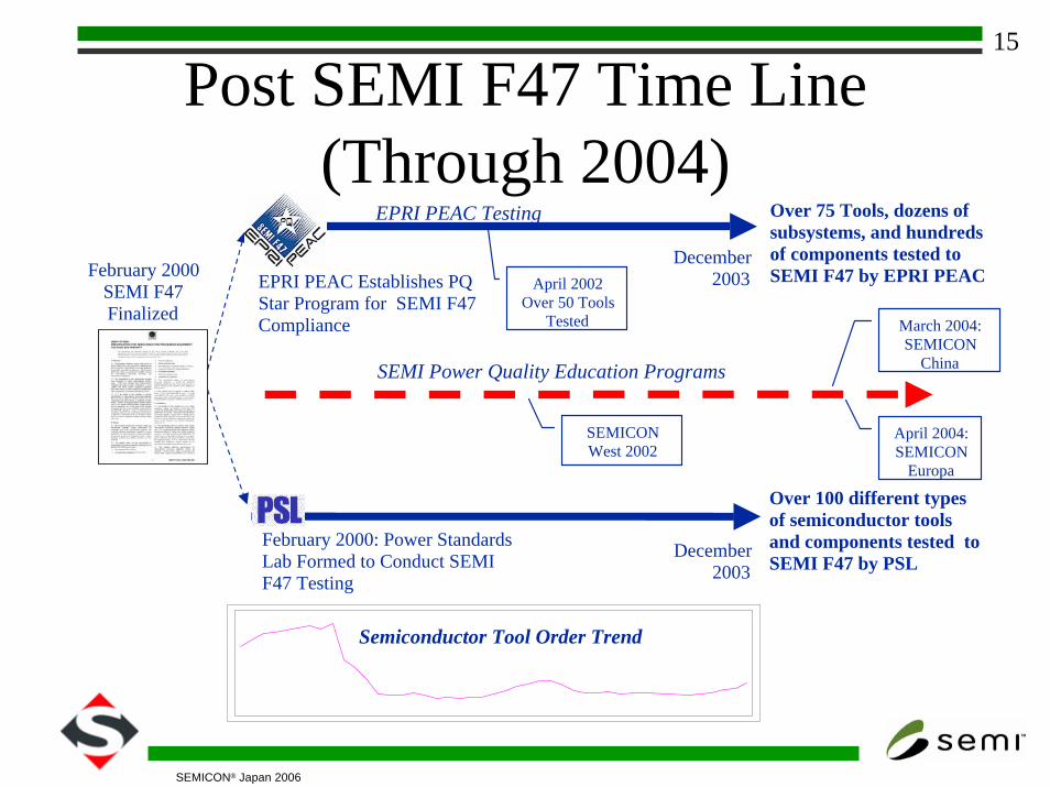
Post SEMI F47 Time Line (Through 2004)
April 2002Over 50 Tools
Tested
EPRI PEAC Testing
December2003
Over 75 Tools, dozens of subsystems, and hundreds of components tested to SEMI F47 by EPRI PEACFebruary 2000
SEMI F47 Finalized
SEMI Power Quality Education Programs
EPRI PEAC Establishes PQ Star Program for SEMI F47 Compliance
February 2000: Power Standards Lab Formed to Conduct SEMI F47 Testing
Semiconductor Tool Order Trend
SEMICONWest 2002
Over 100 different types of semiconductor tools and components tested to SEMI F47 by PSL
December2003
April 2004:SEMICON
Europa
March 2004:SEMICON
China

16
SEMICON® Japan 2006
Post SEMI F47 ProgressCollectively EPRI Solutions and PSL have evaluated over 200 Semiconductor Tools, as well as hundreds of subsystems and components.
17
SEMICON® Japan 2006
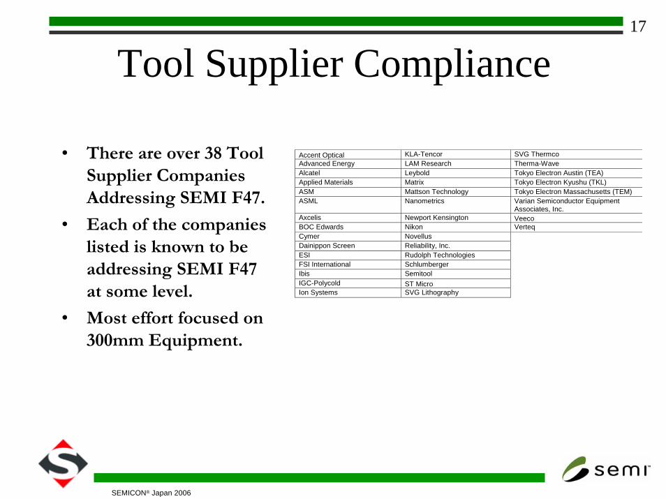
Tool Supplier Compliance
• There are over 38 Tool Supplier Companies Addressing SEMI F47.
• Each of the companies listed is known to be addressing SEMI F47 at some level.
• Most effort focused on 300mm Equipment.
Accent Optical KLA-Tencor SVG Thermco Advanced Energy LAM Research Therma-Wave Alcatel Leybold Tokyo Electron Austin (TEA) Applied Materials Matrix Tokyo Electron Kyushu (TKL) ASM Mattson Technology Tokyo Electron Massachusetts (TEM) ASML Nanometrics Varian Semiconductor Equipment
Associates, Inc. Axcelis Newport Kensington Veeco BOC Edwards Nikon Verteq Cymer Novellus Dainippon Screen Reliability, Inc. ESI Rudolph Technologies FSI International Schlumberger Ibis Semitool IGC-Polycold ST Micro Ion Systems SVG Lithography
18
SEMICON® Japan 2006
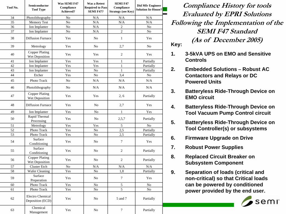
Key:
1. 3-5kVA UPS on EMO and Sensitive Controls
2. Embedded Solutions – Robust AC Contactors and Relays or DC Powered Units
3. Batteryless Ride-Through Device on EMO circuit
4. Batteryless Ride-Through Device on Tool Vacuum Pump Control circuit
5. Batteryless Ride-Through Device on Tool Controller(s) or subsystems
6. Firmware Upgrade on Drive
7. Robust Power Supplies
8. Replaced Circuit Breaker on Subsystem Component
9. Separation of loads (critical and non-critical) so that Critical loads can be powered by conditioned power provided by the end user.
Compliance History for tools Evaluated by EPRI Solutions
Following the Implementation of the SEMI F47 Standard
(As of December 2005)
34 Photolithography No N/A N/A N/A35 Memory Test No N/A N/A N/A36 Ion Implanter No N/A 2 No37 Ion Implanter No N/A 2 No
38 Diffusion Furnace Yes No 1 Yes
39 Metrology Yes No 2,7 No
40 Copper Plating Wet Deposition Yes Yes 2 Yes
41 Ion Implanter Yes Yes 1 Partially42 Ion Implanter Yes Yes 1 Partially43 Ion Implanter Yes No 1 Partially44 Etcher Yes No 3,4 No45 Photo Track No N/A N/A N/A
46 Photolithography No N/A N/A N/A
47 Copper Plating Wet Deposition Yes Yes 2, 6 Partially
48 Diffusion Furnace Yes No 2,7 Yes
49 Ion Implanter Yes No 1 Yes
50 Rapid Thermal Processing Yes No 2,5,7 Partially
51 Metrology Yes Yes 5 No52 Photo Track Yes No 2,5 Partially53 Photo Track Yes No 2,5 Partially
54 Surface Conditioning Yes No 7 Yes
55 Surface Conditioning Yes No 2 Partially
56 Copper Plating Wet Deposition Yes No 2 Partially
57 Cluster Etch No N/A N/A N/A58 Wafer Cleaning Yes No 1,8 Partially
59 Surface Preperation Yes No 7 Yes
60 Photo Track Yes No 5 No61 Photo Track Yes No 5 No
62 Electro Chemical Deposition (ECD) Yes No 5 and 7 Partially
63 Chemical Management Yes No 7 Partially
SEMI F47 Compliance
Strategy (see Key)
Did Mfr Engineer Solution In-House?Tool No. Semiconductor
Tool Type
Was SEMI F47 Compliance Achieved?
Was a Retest Required to Pass
SEMI F47?
19
SEMICON® Japan 2006
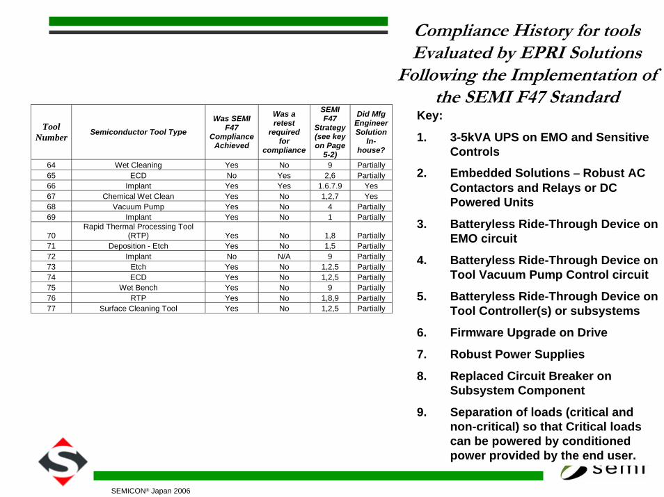
Compliance History for tools Evaluated by EPRI Solutions
Following the Implementation of the SEMI F47 Standard(As of December 2005)Key:
1. 3-5kVA UPS on EMO and Sensitive Controls
2. Embedded Solutions – Robust AC Contactors and Relays or DC Powered Units
3. Batteryless Ride-Through Device on EMO circuit
4. Batteryless Ride-Through Device on Tool Vacuum Pump Control circuit
5. Batteryless Ride-Through Device on Tool Controller(s) or subsystems
6. Firmware Upgrade on Drive
7. Robust Power Supplies
8. Replaced Circuit Breaker on Subsystem Component
9. Separation of loads (critical and non-critical) so that Critical loads can be powered by conditioned power provided by the end user.
Tool Number Semiconductor Tool Type
Was SEMI F47
Compliance Achieved
Was a retest
required for
compliance
SEMI F47
Strategy (see key on Page
5-2)
Did Mfg Engineer Solution
In-house?
64 Wet Cleaning Yes No 9 Partially 65 ECD No Yes 2,6 Partially 66 Implant Yes Yes 1.6.7.9 Yes 67 Chemical Wet Clean Yes No 1,2,7 Yes 68 Vacuum Pump Yes No 4 Partially 69 Implant Yes No 1 Partially
70 Rapid Thermal Processing Tool
(RTP) Yes No 1,8 Partially 71 Deposition - Etch Yes No 1,5 Partially 72 Implant No N/A 9 Partially 73 Etch Yes No 1,2,5 Partially 74 ECD Yes No 1,2,5 Partially 75 Wet Bench Yes No 9 Partially 76 RTP Yes No 1,8,9 Partially 77 Surface Cleaning Tool Yes No 1,2,5 Partially
20
SEMICON® Japan 2006
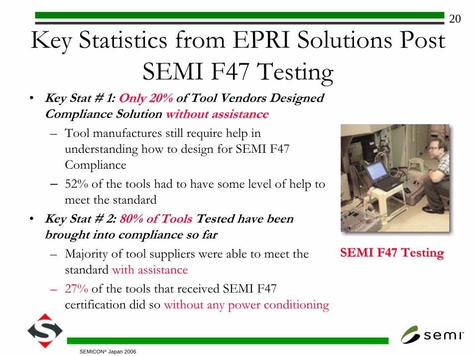
Key Statistics from EPRI Solutions Post SEMI F47 Testing
• Key Stat # 1: Only 20% of Tool Vendors Designed Compliance Solution without assistance– Tool manufactures still require help in
understanding how to design for SEMI F47 Compliance
– 52% of the tools had to have some level of help to meet the standard
• Key Stat # 2: 80% of Tools Tested have been brought into compliance so far– Majority of tool suppliers were able to meet the
standard with assistance– 27% of the tools that received SEMI F47
certification did so without any power conditioning
SEMI F47 TestingSEMI F47 Testing
21
SEMICON® Japan 2006
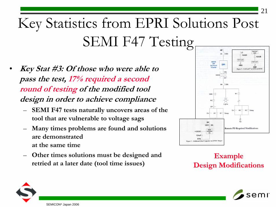
Key Statistics from EPRI Solutions Post SEMI F47 Testing
• Key Stat #3: Of those who were able to pass the test, 17% required a second round of testing of the modified tool design in order to achieve compliance
– SEMI F47 tests naturally uncovers areas of the tool that are vulnerable to voltage sags
– Many times problems are found and solutions are demonstratedat the same time
– Other times solutions must be designed and retried at a later date (tool time issues)
ExampleExampleDesign ModificationsDesign Modifications
22
SEMICON® Japan 2006
Key Statistics from EPRI Solutions Post SEMI F47 Testing
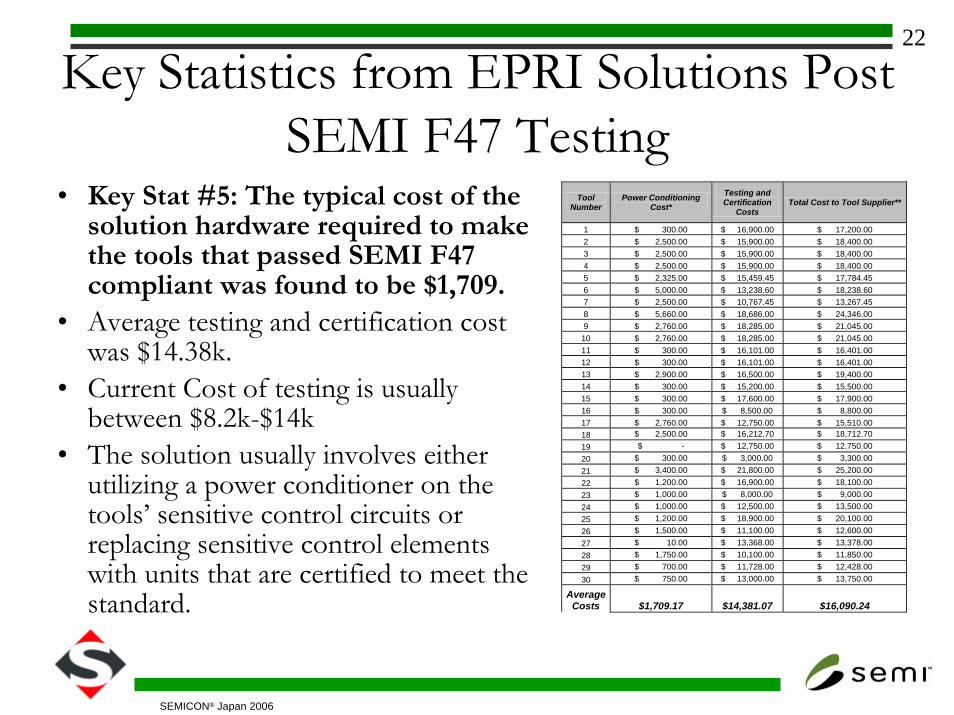
• Key Stat #5: The typical cost of the solution hardware required to make the tools that passed SEMI F47 compliant was found to be $1,709.
• Average testing and certification cost was $14.38k.
• Current Cost of testing is usually between $8.2k-$14k
• The solution usually involves either utilizing a power conditioner on the tools’ sensitive control circuits or replacing sensitive control elements with units that are certified to meet the standard.
Tool Number
Power Conditioning Cost*
Testing and Certification
Costs Total Cost to Tool Supplier**
1 $ 300.00 $ 16,900.00 $ 17,200.00 2 $ 2,500.00 $ 15,900.00 $ 18,400.00 3 $ 2,500.00 $ 15,900.00 $ 18,400.00 4 $ 2,500.00 $ 15,900.00 $ 18,400.00 5 $ 2,325.00 $ 15,459.45 $ 17,784.45 6 $ 5,000.00 $ 13,238.60 $ 18,238.60 7 $ 2,500.00 $ 10,767.45 $ 13,267.45 8 $ 5,660.00 $ 18,686.00 $ 24,346.00 9 $ 2,760.00 $ 18,285.00 $ 21,045.00 10 $ 2,760.00 $ 18,285.00 $ 21,045.00 11 $ 300.00 $ 16,101.00 $ 16,401.00 12 $ 300.00 $ 16,101.00 $ 16,401.00 13 $ 2,900.00 $ 16,500.00 $ 19,400.00 14 $ 300.00 $ 15,200.00 $ 15,500.00 15 $ 300.00 $ 17,600.00 $ 17,900.00 16 $ 300.00 $ 8,500.00 $ 8,800.00 17 $ 2,760.00 $ 12,750.00 $ 15,510.00 18 $ 2,500.00 $ 16,212.70 $ 18,712.70 19 $ - $ 12,750.00 $ 12,750.00 20 $ 300.00 $ 3,000.00 $ 3,300.00 21 $ 3,400.00 $ 21,800.00 $ 25,200.00 22 $ 1,200.00 $ 16,900.00 $ 18,100.00 23 $ 1,000.00 $ 8,000.00 $ 9,000.00 24 $ 1,000.00 $ 12,500.00 $ 13,500.00 25 $ 1,200.00 $ 18,900.00 $ 20,100.00 26 $ 1,500.00 $ 11,100.00 $ 12,600.00 27 $ 10.00 $ 13,368.00 $ 13,378.00 28 $ 1,750.00 $ 10,100.00 $ 11,850.00 29 $ 700.00 $ 11,728.00 $ 12,428.00 30 $ 750.00 $ 13,000.00 $ 13,750.00
AverageCosts $1,709.17 $14,381.07 $16,090.24
23
SEMICON® Japan 2006
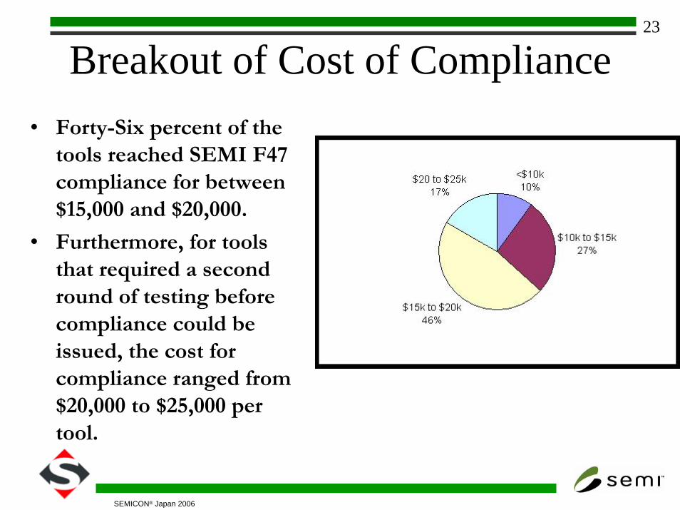
Breakout of Cost of Compliance• Forty-Six percent of the
tools reached SEMI F47 compliance for between $15,000 and $20,000.
• Furthermore, for tools that required a second round of testing before compliance could be issued, the cost for compliance ranged from $20,000 to $25,000 per tool.
24
SEMICON® Japan 2006
In Reality…..
The Price of the Solution The Price of the Solution is small compared to is small compared to Costs associated with Costs associated with
Lost Product,Downtime Lost Product,Downtime and Overall Tool Priceand Overall Tool Price
25
SEMICON® Japan 2006
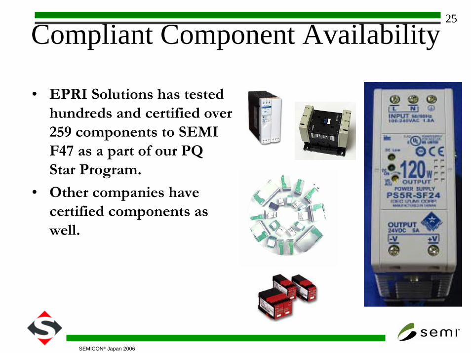
Compliant Component Availability
• EPRI Solutions has tested hundreds and certified over 259 components to SEMI F47 as a part of our PQ Star Program.
• Other companies have certified components as well.
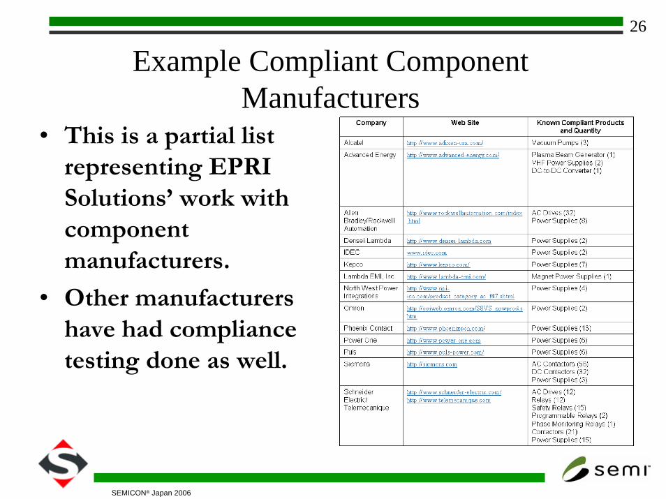
26
SEMICON® Japan 2006
Example Compliant ComponentManufacturers
• This is a partial list representing EPRI Solutions’ work with component manufacturers.
• Other manufacturers have had compliance testing done as well.
27
SEMICON® Japan 2006
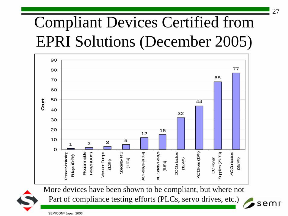
Compliant Devices Certified fromEPRI Solutions (December 2005)
More devices have been shown to be compliant, but where notPart of compliance testing efforts (PLCs, servo drives, etc.)
1 2 3 5
1215
32
44
68
77
0
10
20
30
40
50
60
70
80
90Pha
se M
onito
ring
Relay
s (0
.4%
)
Pro
gram
mab
le
Relay
s (0
.8%
)
Vac
uum
Pum
ps
(1.2
%)
Spe
cialty
P/S
(1.9
%)
AC R
elay
s (4
.6%
)
AC S
afet
y Relay
s
(5.8
%)
DC C
onta
ctor
s
(12.
4%)
AC D
rives
(17%
)
DC P
ower
Sup
plies
(26.
3%)
AC C
onta
ctor
s
(29.
7%)
Cou
nt
28
SEMICON® Japan 2006
Device Test Details• Tests conducted at 50
and 60 Hz.
• For DC Power Supplies, tests conducted at 50 and 60 Hz, multiple load levels, and at different input voltages (120/208).
• For drives also conducted at multiple input voltages, load levels, and frequencies.
Telemecanique CA2KN22L7Voltage Sag Ride Through Curve
0%
20%
40%
60%
80%
100%
0 0.1 0.2 0.3 0.4 0.5 0.6 0.7 0.8 0.9 1Duration (in seconds)
Volta
ge (%
of N
omin
al)
DUT 60HZ SEMI F47 DUT 50HZ
29
SEMICON® Japan 2006
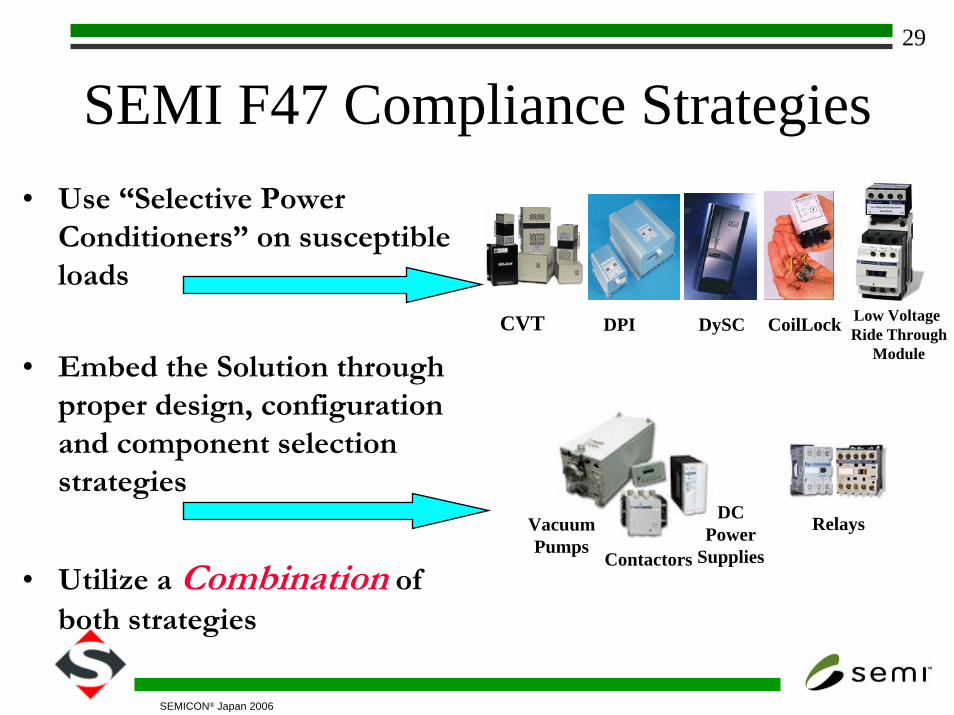
SEMI F47 Compliance Strategies• Use “Selective Power
Conditioners” on susceptible loads
• Embed the Solution through proper design, configuration and component selection strategies
• Utilize a Combination of both strategies
DPI DySC CoilLockCVT
VacuumPumps
Contactors
DCPower
Supplies
Low VoltageRide Through
Module
Relays
30
SEMICON® Japan 2006
Conclusions• Progress has been made in developing tools that
are more robust to voltage sags.• Tool vendors are beginning to understand the
issues surrounding power quality and designing systems with voltage sags in mind.
• Semiconductor manufacturers believe the progress has not been fast enough (economy may be partly to blame in short term)
• Proactive component and voltage sag mitigation suppliers have stepped forth to have their products certified to the standard and/or integrated into tool solutions.


![4760 info 2downloads.semi.org/web/wstandards.nsf/DBBDE62E1EB8B... · 2021. 8. 12. · pod - a box having a standardized mechanical interface [SEMI E19, E47.1] substrate - the basic](https://img.pdfslide.net/doc/110x75/6148f7619241b00fbd674116/4760-info-2021-8-12-pod-a-box-having-a-standardized-mechanical-interface.jpg)