Embed Size (px)
Citation preview

Doc. no. LAL Env Mon Plan Rev. no. V0.1 Project ID London Array Ltd Prepared Keith Henson, London Array, February 2010
Pre-Construction Marine Environmental Monitoring Plan
London Array Offshore Wind Farm February 2010

London Array Phase 1 Environmental Monitoring Plan February 2010
Introduction
The Proposed Development, Objectives of the Marine Environmental Monitoring Plan, Hypothesis Theory, Proposed Monitoring Schedule for London Array Phase 1, Monitoring Surveys Covered, Reporting
Environmental Monitoring Plans Bathymetric Survey Sabellaria spinulosa Benthic Monitoring Fishery Monitoring Survey Electromagnetic Field Desk Study

London Array Phase 1 Environmental Monitoring Plan February 2010
London Array Ltd 1
1. - Introduction 1.1 - The Proposed Development London Array Ltd has obtained all the necessary consents required to construct the London Array offshore wind farm. FEPA consent 32945/07/1 was originally issued in December 2006, and has subsequently been revised such that the current version (32945/09/0) was issued in February 2009. As well as providing details of the proposed schemes, the FEPA license for the London Array offshore wind farm also sets out the responsibilities of the developer with respect to environmental monitoring for the project. These responsibilities include a requirement to undertake surveys during the pre-construction, during construction and post-construction (operational) phases of the projects. It should be noted that under the terms of the existing FEPA license issued in February 2009 (32945/09/0), a maximum of 175 turbines are permitted to be built, out of the total 341 turbines that may eventually be installed. This initial build of 175 turbines will be described as Phase 1 of the project and Figure 1 shows the Phase 1 development area. 1.2 - Objective of this Marine Environmental Monitoring Plan This document is the pre-construction Environmental Monitoring Plan for Phase 1 of the London Array project. An Environmental Plan for subsequent phases of the wind farm development will be produced and submitted accordingly, and following a recommendation from the Ornithological Review Panel that these phases can go ahead. It is based on the requirements of the FEPA License (32945/09/0) The document is intended to provide details on:
• The range of environmental monitoring proposed for the project; • The specifications of the proposed monitoring; • The provisional programme for all proposed monitoring; and • The proposed approach to reporting and presenting the findings of these surveys.
London Array Phase 1 Marine Environmental Monitoring Plan February 2010
London Array Ltd 2
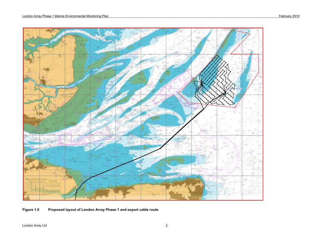
Figure 1.0 Proposed layout of London Array Phase 1 and export cable route
London Array Phase 1 Environmental Monitoring Plan February 2010
London Array Ltd 3
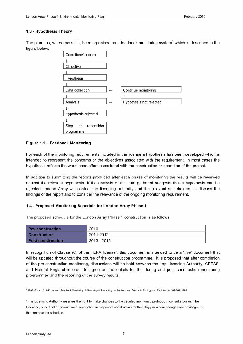
1.3 - Hypothesis Theory The plan has, where possible, been organised as a feedback monitoring system1 which is described in the figure below: Condition/Concern ↓ Objective ↓ Hypothesis ↓ Data collection ← Continue monitoring ↓ ↑ Analysis → Hypothesis not rejected ↓ Hypothesis rejected ↓ Stop or reconsider
programme
Figure 1.1 – Feedback Monitoring For each of the monitoring requirements included in the license a hypothesis has been developed which is intended to represent the concerns or the objectives associated with the requirement. In most cases the hypothesis reflects the worst case effect associated with the construction or operation of the project. In addition to submitting the reports produced after each phase of monitoring the results will be reviewed against the relevant hypothesis. If the analysis of the data gathered suggests that a hypothesis can be rejected London Array will contact the licensing authority and the relevant stakeholders to discuss the findings of the report and to consider the relevance of the ongoing monitoring requirement. 1.4 - Proposed Monitoring Schedule for London Array Phase 1 The proposed schedule for the London Array Phase 1 construction is as follows:
Pre-construction 2010 Construction 2011-2012 Post construction 2013 - 2015
In recognition of Clause 9.1 of the FEPA license2, this document is intended to be a “live” document that will be updated throughout the course of the construction programme. It is proposed that after completion of the pre-construction monitoring, discussions will be held between the key Licensing Authority, CEFAS, and Natural England in order to agree on the details for the during and post construction monitoring programmes and the reporting of the survey results.
1 1993, Gray, J.S. & K. Jensen, Feedback Monitoring: A New Way of Protecting the Environment. Trends in Ecology and Evolution, 8: 267-268. 1993.
2 The Licensing Authority reserves the right to make changes to the detailed monitoring protocol, in consultation with the
Licensee, once final decisions have been taken in respect of construction methodology or where changes are envisaged to
the construction schedule.

London Array Phase 1 Environmental Monitoring Plan February 2010
London Array Ltd 4
This will entail the submission of three separate monitoring plans (pre-construction (Feb 2010); during construction (Oct 2010); post-construction (Jun 2012)), to enable the latest guidance to be used when completing surveys offshore. 1.5 - Monitoring Surveys Covered Proposed survey methodologies and plans for the following are included within this pre-construction document
• Bathymetric Surveys (Side Scan and Multi Beam); • Sabellaria spinulosa (Reef identification and reef population abundance); • Benthic and Epibenthic (Grabs and Trawls); • Fish Survey (Otter and Beam Trawls); • Electromagnetic Fields Desk Review
N.B. Ornithological surveys have not been included within this document until a survey procedure has been agreed with the London Array Ornithological Review Panel3, this will be July 2010. 1.6 - Reporting All surveys will produce the following:
• executive summary of results • assessment of data quality • detailed discussion of results (including interpretation) • ‘accuracy’ of results presented • data examples
All reports will be submitted according to timescales stated within the FEPA license issued for London Array Phase 1.
3 London Array LTD, Natural England, RSPB
London Array Phase 1 Environmental Monitoring Plan February 2010
London Array Ltd 5
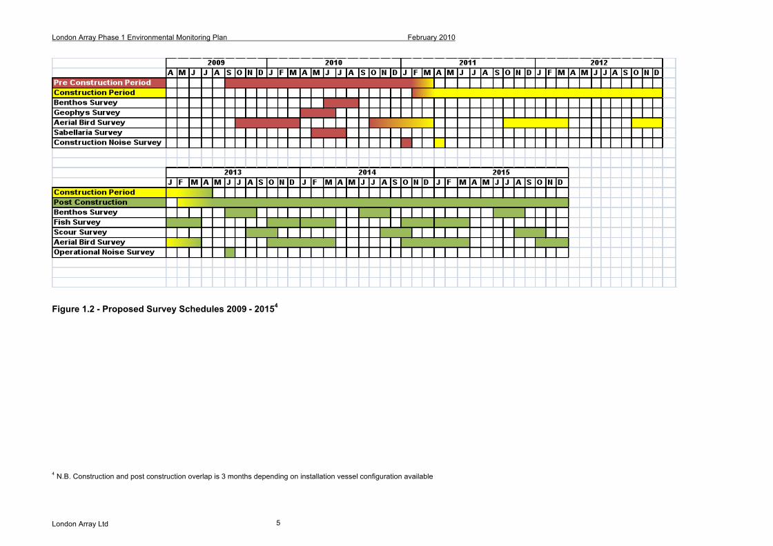
Figure 1.2 - Proposed Survey Schedules 2009 - 20154
4 N.B. Construction and post construction overlap is 3 months depending on installation vessel configuration available
London Array Phase 1 Marine Environmental Monitoring Plan February 2010
London Array Ltd 6
2. - Environmental Monitoring Plans 2.1 - Bathymetric Surveys (Multibeam, Side Scan Sonar) 2.1.1 - Need for Survey FEPA license 32945/09/0 contains consent conditions that set out a requirement to undertake pre-construction baseline and post-construction bathymetric surveys. The exact wording of these consent clauses are provided below.
Relevant FEPA Consent Clause(s)
Description
9.34 The Licence Holder must undertake a bathymetric survey around a sample of adja-cent turbines (minimum of four) and at cable crossings within 3 months of the date that construction of the wind farm is complete, to assess changes in the bathymetry within the array and at cable crossings. The number of turbines and the area of seabed and cable crossing surveyed should be determined in consultation with the Licensing Authority based on the outputs of the computer models used to inform the environmental statement.
9.35 The Licence Holder must carry out similar surveys as in Condition 9.34 in the event of any major storm events likely to result in significant sediment movements (i.e. greater than a 1 in 10 year wave event at this site in terms of wave height).
9.36 The Licence Holder must undertake two5 (one winter and one summer) high-resolution swath bathymetric surveys (including a pre-construction baseline) of the wind farm array and cable route to assess the extent of any bedform morphology.
2.1.2 - Objectives
• To provide geophysical data • To provide accurate bathymetry of the area • To provide information on possible manmade objects in the area. • To provide information on possible Sabellaria spinulosa reef. • To provide a field operations report which comprehensively summarises all the survey systems, parameters, procedures, problems encountered, solutions adopted and HSE incidents and near incidents • To produce a comprehensive interpretative report on the survey results obtained to assist the foundation installations • To consider any changes in bathymetry detected between the environmental statement and the current data.
5 Survey frequency determined in consultation with Natural England and CEFAS, Email, Fawcette A. 08-02-2010
London Array Phase 1 Marine Environmental Monitoring Plan February 2010
London Array Ltd 7
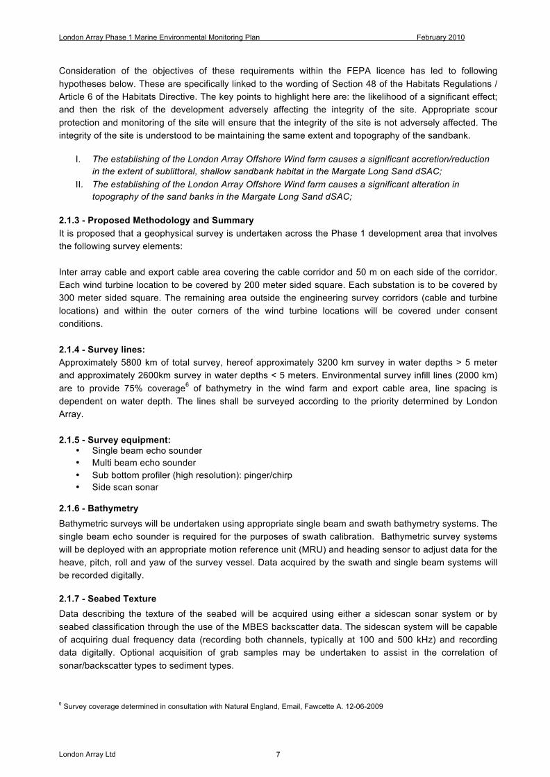
Consideration of the objectives of these requirements within the FEPA licence has led to following hypotheses below. These are specifically linked to the wording of Section 48 of the Habitats Regulations / Article 6 of the Habitats Directive. The key points to highlight here are: the likelihood of a significant effect; and then the risk of the development adversely affecting the integrity of the site. Appropriate scour protection and monitoring of the site will ensure that the integrity of the site is not adversely affected. The integrity of the site is understood to be maintaining the same extent and topography of the sandbank.
I. The establishing of the London Array Offshore Wind farm causes a significant accretion/reduction in the extent of sublittoral, shallow sandbank habitat in the Margate Long Sand dSAC;
II. The establishing of the London Array Offshore Wind farm causes a significant alteration in topography of the sand banks in the Margate Long Sand dSAC;
2.1.3 - Proposed Methodology and Summary It is proposed that a geophysical survey is undertaken across the Phase 1 development area that involves the following survey elements: Inter array cable and export cable area covering the cable corridor and 50 m on each side of the corridor. Each wind turbine location to be covered by 200 meter sided square. Each substation is to be covered by 300 meter sided square. The remaining area outside the engineering survey corridors (cable and turbine locations) and within the outer corners of the wind turbine locations will be covered under consent conditions. 2.1.4 - Survey lines: Approximately 5800 km of total survey, hereof approximately 3200 km survey in water depths > 5 meter and approximately 2600km survey in water depths < 5 meters. Environmental survey infill lines (2000 km) are to provide 75% coverage6 of bathymetry in the wind farm and export cable area, line spacing is dependent on water depth. The lines shall be surveyed according to the priority determined by London Array. 2.1.5 - Survey equipment:
• Single beam echo sounder • Multi beam echo sounder • Sub bottom profiler (high resolution): pinger/chirp • Side scan sonar
2.1.6 - Bathymetry Bathymetric surveys will be undertaken using appropriate single beam and swath bathymetry systems. The single beam echo sounder is required for the purposes of swath calibration. Bathymetric survey systems will be deployed with an appropriate motion reference unit (MRU) and heading sensor to adjust data for the heave, pitch, roll and yaw of the survey vessel. Data acquired by the swath and single beam systems will be recorded digitally. 2.1.7 - Seabed Texture Data describing the texture of the seabed will be acquired using either a sidescan sonar system or by seabed classification through the use of the MBES backscatter data. The sidescan system will be capable of acquiring dual frequency data (recording both channels, typically at 100 and 500 kHz) and recording data digitally. Optional acquisition of grab samples may be undertaken to assist in the correlation of sonar/backscatter types to sediment types.
6 Survey coverage determined in consultation with Natural England, Email, Fawcette A. 12-06-2009
London Array Phase 1 Marine Environmental Monitoring Plan February 2010
London Array Ltd 8
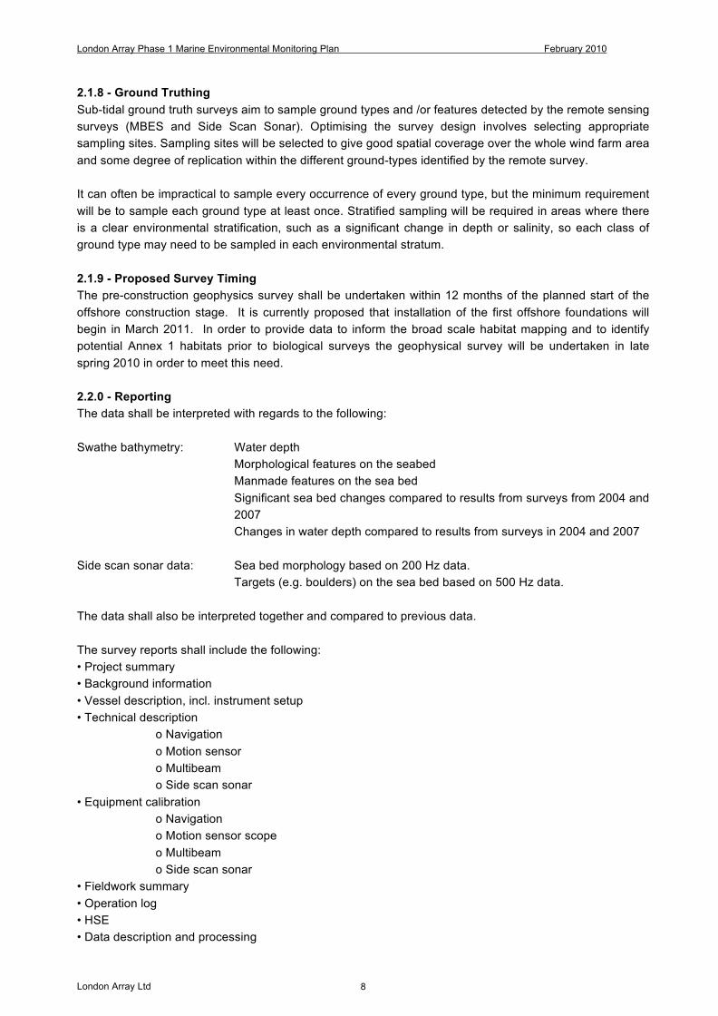
2.1.8 - Ground Truthing Sub-tidal ground truth surveys aim to sample ground types and /or features detected by the remote sensing surveys (MBES and Side Scan Sonar). Optimising the survey design involves selecting appropriate sampling sites. Sampling sites will be selected to give good spatial coverage over the whole wind farm area and some degree of replication within the different ground-types identified by the remote survey. It can often be impractical to sample every occurrence of every ground type, but the minimum requirement will be to sample each ground type at least once. Stratified sampling will be required in areas where there is a clear environmental stratification, such as a significant change in depth or salinity, so each class of ground type may need to be sampled in each environmental stratum. 2.1.9 - Proposed Survey Timing The pre-construction geophysics survey shall be undertaken within 12 months of the planned start of the offshore construction stage. It is currently proposed that installation of the first offshore foundations will begin in March 2011. In order to provide data to inform the broad scale habitat mapping and to identify potential Annex 1 habitats prior to biological surveys the geophysical survey will be undertaken in late spring 2010 in order to meet this need. 2.2.0 - Reporting The data shall be interpreted with regards to the following: Swathe bathymetry: Water depth
Morphological features on the seabed Manmade features on the sea bed Significant sea bed changes compared to results from surveys from 2004 and 2007 Changes in water depth compared to results from surveys in 2004 and 2007
Side scan sonar data: Sea bed morphology based on 200 Hz data.
Targets (e.g. boulders) on the sea bed based on 500 Hz data.
The data shall also be interpreted together and compared to previous data. The survey reports shall include the following: • Project summary • Background information • Vessel description, incl. instrument setup • Technical description
o Navigation o Motion sensor o Multibeam o Side scan sonar
• Equipment calibration o Navigation o Motion sensor scope o Multibeam o Side scan sonar
• Fieldwork summary • Operation log • HSE • Data description and processing

London Array Phase 1 Marine Environmental Monitoring Plan February 2010
London Array Ltd 9
o Multibeam echosounder o Side scan sonar
• Uncertainties of interpretation • Results
o Possible Sabellaria spinulosa reef o Estimated seabed movements
• References The report shall comprise the following charts at A1 or A3 paper size • General charts size 1:10.000 or best alternative (paper size A1) and charts size 1:20.000 or best alternative (paper size A3)
o Track plot o Bathymetry o Isopach o Depth o Target plot
• Vertical profiles along all turbine E-W and N-S lines. Size 1:5.000 horizontal / 1:250 vertical or best alternative (paper size A1) and 1:10.000 horizontal / 1:500 vertical or best alternative (paper size A3). Data interpretation for all reports shall have incorporated and integrated all pertinent existing and available information including: • Soil data (including that previously acquired) • Previous survey data • Geotechnical information • Public domain data The terminology of shallow soils units used on the charts and in the survey report shall be consistent. The description of deeper geological formations shall be consistent with that used by London Array. Unless otherwise requested, all depths shall be in metres, heights and distances shall be in metres. Water depths shall be referred to lowest astronomical tide. Soils information in relation to foundation conditions shall be referenced to seabed datum. Track and bathymetric charts shall show as a minimum the following:
• UTM grid lines • Geographical grid • Grid North arrow • Proposed location of wind turbines • Contours at a maximum of 0.5m • All pipelines, cables, umbilicals and subsea structures to be annotated • Location and annotation of debris • Sample locations

London Array Phase 1 Marine Environmental Monitoring Plan February 2010
London Array Ltd 10
3.1 - Sabellaria spinulosa Survey 3.1.1 - Need for Survey The exact wording within FEPA consent 32945/09/0 that states the requirement to undertake an Annex I survey is detailed below.
Relevant FEPA Consent Clause(s)
Description
9.8 The Licence Holder must carry out a pre-construction survey to determine the location and abundance of Sabellaria spinulosa in the vicinity of the array and cable route. Should Sabellaria spinulosa reef or reef-like structures be identi-fied in the area of the proposed array the licence holder is required to under-take an assessment of the need to micro-site individual turbine structures, inter-array cables or the export cable. If micro-siting is required the Licence Holder must inform the Licensing Authority immediately. The results of the survey and assessment shall be submitted to the Licensing Authority and Natural England within one month of the completion of the survey and no construction is to commence without the written agreement of the Licensing Authority.
Annex 1 – Point 4
A pre-construction survey to determine the location and abundance of Sabel-laria spinulosa with particular reference to reef and reef-like structures should be undertaken in the proposed turbine array area and along the export cable route.
3.1.2 - Aims and Objectives
• Analysis of broad scale sidescan data (survey to be undertaken in spring 2010) for the London Array development area to identify areas for fine scale survey using drop down video.
• Fine scale survey using drop down video within areas assessed as having potential for Sabellaria spinulosa or other reef structures.
• Broad scale sidescan survey 100kHz and 500kHz of the cable route corridor (Ground truthing of broad and fine scale mapping data using existing Day grab sample data (Subject to approval for use of grab from Natural England)
• Assessment using ‘reefiness’ scoring system (Hendrick and Foster-Smith, 2007, and Gubbay, 2007).
• Provision of detailed GIS biotope maps to facilitate micro-siting of turbines, inter-array cables and export cable if requirement is identified.
3.1.3 - Field Survey Methodology – Sabellaria spinulosa The drop down video will be deployed at targets identified from the existing biotope map, and from geophysical data to be collected in Spring 2010 and will include inspection of any potential targets along the interturbine cable route areas where these have been identified from the Side Scan and swath data. Geophysical data collected along the export cable route will also be analysed to assess areas of potential reef habitat. Any potential reef targets will be ground-truthed using seabed imagery. This will include areas previously identified by grab sampling as supporting Sabellaria spinulosa reef. During the geophysical survey in early 2010, a draft Sabellaria spinulosa report will be produced for discussion with the contractor prior to further discussions with Natural England and the Marine Management Organisation. It is anticipated that the outcome of these discussions will finalise the scope of Sabellaria spinulosa investigations.

London Array Phase 1 Marine Environmental Monitoring Plan February 2010
London Array Ltd 11
Drop down video survey technique using a Fluid Lens Camera system to ground truth the geophysical seabed ‘map’ and provide fine scale observations of habitats in-situ. The drop down video shall be deployed at targets identified from the existing biotope map, and from geophysical data to be collected in Spring 2010 and will include inspection of any potential targets along the inter-turbine cable route areas where these have been identified from the Side Scan and swath data. A minimum of 5 images will be collected at each drop. Where ‘possible’ reef or reef-type structure is detected then video drops should be extended to validate the percentage cover-age (patchiness) of Sabellaria spinulosa tube structures and ground-truth the extent of the habitat. This should be conducted until such time that confidence in interpreting the underpinning remote sensing data is achieved. A field log shall be used to record each sample retrieved (date, time, position) with an initial description.
Index of Aggregation ‘quality’ Basis of definition Means of measurement/detection
Elevation Average or maximum tube heights Estimated measured from seabed imagery and
potentially sidescan
Sediment coalescence and
stability
Colony should bind sediment and
smother/replace existing substratum
Seabed imagery
Spatial extent Area covered by aggregation Side scan sonar data supplemented by biological
ground truthing and seabed imagery
Cover/patchiness % cover of substratum by aggrega-
tion. Dispersion scattered versus
clumped.
Side scan sonar and seabed imagery used to
assess percentage cover
Sabellaria spinulosa density Average and maximum density of S.
Spinulosa per m2
The abundance of Sabellaria spinulosa recorded
from grab samples supplemented by anecdotal
notes of epifaunal species from seabed imagery
Biodiversity and species
richness
Elevated relative to similar non-
Sabellaria spinulosa habitats in
vicinity. Qualitatively different spe-
cies complement
Grab data analysed using univariate and multi-
variate techniques to establish differences be-
tween the Sabellaria spinulosa aggregations and
adjacent substrate
Characteristic species Contains species considered char-
acteristic of the MNCR Sabellaria
spinulosa biotopes
Species found identified in each Sabellaria spinu-
losa aggregation from grab sample data matched
with those listed under the MNCR classifications
to produce an ‘in common’ list
Temporal stability Degree of presence/ likely absence Comparisons of 2002 and 2007 datasets for
evidence of the aggregations longevity
Table 2.1 Sabellaria spinulosa reef definitions - Adapted from Hendrick and Foster-Smith (2006)7 and Pearce et al., (2007)8. Measure of ‘reefiness’ NOT a REEF LOW MEDIUM HIGH
Elevation (cm) (average
tube height)
<2 2-5 5-10 >10
Area (m2) <25 25-10,000 10,000-1,000,000 >1,000,000
Patchiness (% cover) <10% 10-20 20-30 >30
Table 2.2 Ranges of figures which could be used as a measure of ’reefiness’ (Gubbay, 20079).
7 Hendrick, V.J. and Foster-Smith, R.L. 2006. Sabellaria spinulosa reef: a scoring system for evaluating ‘reefiness’ in the context of
the Habitats Directive. J. Mar. Biol. Ass. UK. 86, 665-677. 8 Pearce, B. Taylor, J. and Seiderer, L.J. 2007. Recoverability of Sabellaria spinulosa Following Aggregate Extraction. Aggre-gate Levy Sustainability Fund MAL0027. Marine Ecological Surveys Limited, 24a Monmouth Place, Bath, BA1 2AY. 87pp. ISBN 978-0-9506920-1-2.
London Array Phase 1 Marine Environmental Monitoring Plan February 2010
London Array Ltd 12
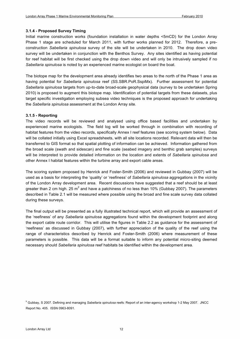
3.1.4 - Proposed Survey Timing Initial marine construction works (foundation installation in water depths <5mCD) for the London Array Phase 1 stage are scheduled for March 2011, with further works planned for 2012. Therefore, a pre-construction Sabellaria spinulosa survey of the site will be undertaken in 2010. The drop down video survey will be undertaken in conjunction with the Benthos Survey. Any sites identified as having potential for reef habitat will be first checked using the drop down video and will only be intrusively sampled if no Sabellaria spinulosa is noted by an experienced marine ecologist on board the boat. The biotope map for the development area already identifies two areas to the north of the Phase 1 area as having potential for Sabellaria spinulosa reef (SS.SBR.PoR.SspiMx). Further assessment for potential Sabellaria spinulosa targets from up-to-date broad-scale geophysical data (survey to be undertaken Spring 2010) is proposed to augment this biotope map. Identification of potential targets from these datasets, plus target specific investigation employing subsea video techniques is the proposed approach for undertaking the Sabellaria spinulosa assessment at the London Array site. 3.1.5 - Reporting The video records will be reviewed and analysed using office based facilities and undertaken by experienced marine ecologists. The field log will be worked through in combination with recording of habitat features from the video records, specifically Annex I reef features (see scoring system below). Data will be collated initially using Excel spreadsheets, with all site locations recorded. Relevant data will then be transferred to GIS format so that spatial plotting of information can be achieved. Information gathered from the broad scale (swath and sidescan) and fine scale (seabed imagery and benthic grab samples) surveys will be interpreted to provide detailed information on the location and extents of Sabellaria spinulosa and other Annex I habitat features within the turbine array and export cable areas. The scoring system proposed by Henrick and Foster-Smith (2006) and reviewed in Gubbay (2007) will be used as a basis for interpreting the ‘quality’ or ‘reefiness’ of Sabellaria spinulosa aggregations in the vicinity of the London Array development area. Recent discussions have suggested that a reef should be at least greater than 2 cm high. 25 m2 and have a patchiness of no less than 10% (Gubbay 2007). The parameters described in Table 2.1 will be measured where possible using the broad and fine scale survey data collated during these surveys. The final output will be presented as a fully illustrated technical report, which will provide an assessment of the ‘reefiness’ of any Sabellaria spinulosa aggregations found within the development footprint and along the export cable route corridor. This will utilise the figures in Table 2.2 as guidance for the assessment of ‘reefiness’ as discussed in Gubbay (2007), with further appreciation of the quality of the reef using the range of characteristics described by Henrick and Foster-Smith (2006) where measurement of these parameters is possible. This data will be a format suitable to inform any potential micro-siting deemed necessary should Sabellaria spinulosa reef habitats be identified within the development area.
9 Gubbay, S 2007. Defining and managing Sabellaria spinulosa reefs: Report of an inter-agency workshop 1-2 May 2007. JNCC
Report No. 405. ISSN 0963-8091.

London Array Phase 1 Marine Environmental Monitoring Plan February 2010
London Array Ltd 13
4.1 - Benthic Monitoring 4.1.1 - Need for Survey The exact wording within FEPA consent 32945/09/0 that states the requirement to undertake benthic surveys is provided below.
Relevant FEPA Consent Clause(s)
Description
9.7 The Licence Holder must carry out a programme of sedimentary, hydrological, ben-thic, ornithological and other monitoring, as outlined in Annex 1 and Annex 2 at-tached to this Schedule. The full specification for the monitoring programme will be subject to separate written agreement with the Licensing Authority following consul-tation with CEFAS and Natural England at least four months prior to the proposed commencement of the monitoring work.
Annex I – Point 4
Sample locations for ongoing monitoring must be determined by factors such as precise monopile locations, location of cables etc. Sample locations must also take full account of factors such as sensitive areas, coastal processes modelling outputs (for sediment transport/deposition information) and geophysical surveys (to ensure adequate coverage of seabed habitats). Sampling should involve a minimum of three replicates at each station and the number and location of stations should be determined making use of the data used to characterise the site as part of the environmental statement. This monitoring should include a suitable baseline data set and make adequate use of control sites. Colonisation of monopiles and scour protection must be determined by video obser-vations and analysis with some accompanying sample collection for verification and identification. NB – the sedimentary and benthic data sets must be closely related.
Consideration of the objectives of these requirements has led to the following hypothesis:
• The establishing of the London Array Offshore Wind farm leads to significant changes in benthic organisms at the wind farm site
• The establishing of the London Array Offshore Wind farm causes a significant change in sediment composition across the sandbanks in the Margate Long Sand dSAC.
4.1.2 - Proposed Methodology It is proposed that a benthic survey is undertaken across the Phase 1 development area that involves the following survey elements:
• Benthic Grabs; • Epibenthic Trawls; • Benthic Faunal Preservation; • Biomass Determination; • Particle Size Analysis (PSA); • Total Organic Carbon Content (TOC)
London Array Phase 1 Marine Environmental Monitoring Plan February 2010
London Array Ltd 14
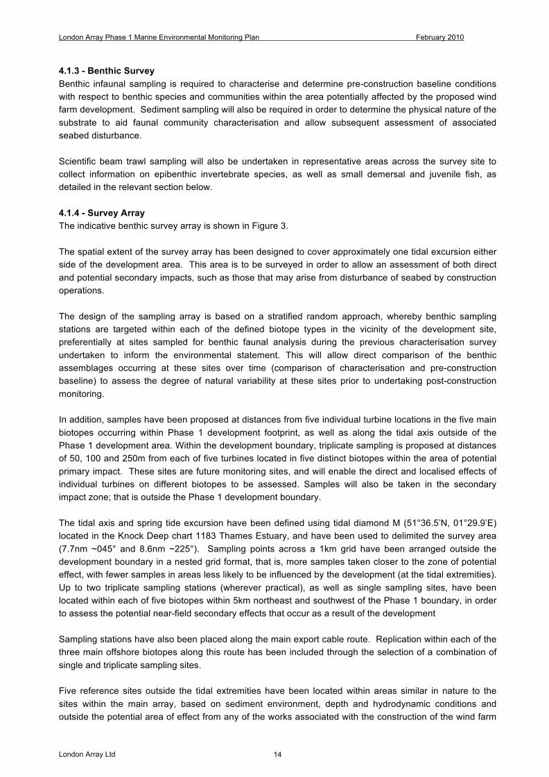
4.1.3 - Benthic Survey Benthic infaunal sampling is required to characterise and determine pre-construction baseline conditions with respect to benthic species and communities within the area potentially affected by the proposed wind farm development. Sediment sampling will also be required in order to determine the physical nature of the substrate to aid faunal community characterisation and allow subsequent assessment of associated seabed disturbance. Scientific beam trawl sampling will also be undertaken in representative areas across the survey site to collect information on epibenthic invertebrate species, as well as small demersal and juvenile fish, as detailed in the relevant section below. 4.1.4 - Survey Array The indicative benthic survey array is shown in Figure 3. The spatial extent of the survey array has been designed to cover approximately one tidal excursion either side of the development area. This area is to be surveyed in order to allow an assessment of both direct and potential secondary impacts, such as those that may arise from disturbance of seabed by construction operations. The design of the sampling array is based on a stratified random approach, whereby benthic sampling stations are targeted within each of the defined biotope types in the vicinity of the development site, preferentially at sites sampled for benthic faunal analysis during the previous characterisation survey undertaken to inform the environmental statement. This will allow direct comparison of the benthic assemblages occurring at these sites over time (comparison of characterisation and pre-construction baseline) to assess the degree of natural variability at these sites prior to undertaking post-construction monitoring. In addition, samples have been proposed at distances from five individual turbine locations in the five main biotopes occurring within Phase 1 development footprint, as well as along the tidal axis outside of the Phase 1 development area. Within the development boundary, triplicate sampling is proposed at distances of 50, 100 and 250m from each of five turbines located in five distinct biotopes within the area of potential primary impact. These sites are future monitoring sites, and will enable the direct and localised effects of individual turbines on different biotopes to be assessed. Samples will also be taken in the secondary impact zone; that is outside the Phase 1 development boundary. The tidal axis and spring tide excursion have been defined using tidal diamond M (51°36.5’N, 01°29.9’E) located in the Knock Deep chart 1183 Thames Estuary, and have been used to delimited the survey area (7.7nm ~045° and 8.6nm ~225°). Sampling points across a 1km grid have been arranged outside the development boundary in a nested grid format, that is, more samples taken closer to the zone of potential effect, with fewer samples in areas less likely to be influenced by the development (at the tidal extremities). Up to two triplicate sampling stations (wherever practical), as well as single sampling sites, have been located within each of five biotopes within 5km northeast and southwest of the Phase 1 boundary, in order to assess the potential near-field secondary effects that occur as a result of the development Sampling stations have also been placed along the main export cable route. Replication within each of the three main offshore biotopes along this route has been included through the selection of a combination of single and triplicate sampling sites. Five reference sites outside the tidal extremities have been located within areas similar in nature to the sites within the main array, based on sediment environment, depth and hydrodynamic conditions and outside the potential area of effect from any of the works associated with the construction of the wind farm
London Array Phase 1 Marine Environmental Monitoring Plan February 2010
London Array Ltd 15
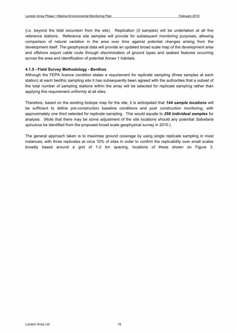
(i.e. beyond the tidal excursion from the site). Replication (3 samples) will be undertaken at all five reference stations. Reference site samples will provide for subsequent monitoring purposes, allowing comparison of natural variation in the area over time against potential changes arising from the development itself. The geophysical data will provide an updated broad scale map of the development area and offshore export cable route through discrimination of ground types and seabed features occurring across the area and identification of potential Annex 1 habitats. 4.1.5 - Field Survey Methodology - Benthos Although the FEPA licence condition states a requirement for replicate sampling (three samples at each station) at each benthic sampling site it has subsequently been agreed with the authorities that a subset of the total number of sampling stations within the array will be selected for replicate sampling rather than applying this requirement uniformly at all sites. Therefore, based on the existing biotope map for the site, it is anticipated that 144 sample locations will be sufficient to define pre-construction baseline conditions and post construction monitoring, with approximately one third selected for replicate sampling. This would equate to 258 individual samples for analysis. (Note that there may be some adjustment of the site locations should any potential Sabellaria spinulosa be identified from the proposed broad scale geophysical survey in 2010.) The general approach taken is to maximise ground coverage by using single replicate sampling in most instances, with three replicates at circa 10% of sites in order to confirm the replicability over small scales broadly based around a grid of 1-2 km spacing, locations of these shown on Figure 3.
London Array Phase 1 Marine Environmental Monitoring Plan February 2010
London Array Ltd 16
Figure 3 Proposed pre-construction benthic survey array for London Array Phase 1

London Array Phase 1 – Marine Environmental Monitoring Plan February 2010
London Array Ltd 17
The survey approach and following analysis of samples has been determined based on guidance included in “Procedural Guideline No. 3-9 – Quantitative sampling of sublittoral sediment biotopes and species using remote operated grabs” included in the JNCC Marine Monitoring Handbook (March 2001), and in line with standard CEFAS guidelines (‘Guidelines for the conducting of benthic studies at aggregate dredging sites’, Boyd et al, 2002). The benthic and PSA sampling shall be collected using a 0.1m2 Hamon grab, as this equipment is appropriate to sample the seabed sediments in this area, comprising coarse gravels and sands. The Hamon grab has a volume of ~12l and is fitted with stainless steel jaws; to allow for sediment chemistry sampling should this be required. The grab will be operated from a suitable vessel licensed for this type of work. A log of sample positions, time, type, water depth and other field notes will be made for later reference. Digital photographs shall be taken of all samples and DGPS derived locations will be provided for all sample locations. Visual descriptions of sediment type shall be made at the time of sampling, together with estimates of sample volume (as a measure of sampler efficiency). Sample containers shall be clearly marked externally with date, sample ID and project name. There shall also be an internal plastic tag carrying the same information, marked using a suitable material. Samples shall be rejected where objects such as stones or shells are suspected to have kept the jaws open or where for any other reason loss of finer fractions of the sediment is suspected. Samples shall be rejected where depth of sediment is less than 5cm unless the sediment is very hard and/or coarse and it is clear that better samples cannot be obtained. Where the first three samples are rejected the site shall be moved at least 50m and further attempts made to obtain samples. Samples shall be at least 4 litres in volume. The remaining sediment shall be washed through a 1mm sieve using a low-pressure deck hose (seawater) and the residue transferred to a pre-labelled bucket with lid and preserved immediately in buffered formalin, to a dilution of approximately 4% w/v. An additional sample label, including date, sample ID and project reference shall be placed inside each sample bucket. The sample shall subsequently be transferred to a laboratory for faunal analysis following completion of the survey. Note that here is limited grabbing allowed within the areas defined as being reef type structures or showing evidence of potential Sabellaria spinulosa, grabbing shall only be undertaken with prior agreement from Natural England which may require further images to be provided. Preservation of reef structure and worm individuals shall follow the methodology that is written within the benthos infaunal preservation. In known Sabellaria spinulosa locations where grabbing is agreed with Natural England, a single sample shall be taken using the 0.1m2 Hamon grab. If the first attempt is below acceptable volume and contains no evidence of Sabellaria spinulosa reef, another attempt to sample at the site will be made. However, if the first attempt contains evidence of Sabellaria spinulosa reef (regardless of acceptable volume being achieved or not), the site will be abandoned and the sample accepted as a low volume sample in an area of reef. In areas where there is no prior evidence of Sabellaria spinulosa standard grabbing protocol will apply. However, if the first attempt is below acceptable volume and contains evidence of Sabellaria spinulosa reef, the site will be abandoned and the sample accepted as a low volume sample in an area of reef. The sample site will be further investigated using drop-down video to ascertain data on the extent and percentage coverage (patchiness) of the reef.
London Array Phase 1 – Marine Environmental Monitoring Plan February 2010
London Array Ltd 18
For sites which require replicates, if evidence of Sabellaria spinulosa reef is found in the first grab sample, the replicate will be moved to the next site in closest proximity. A field log shall be used to record each sample retrieved (date, time, position) with an initial description of sample volume, sediment type and conspicuous fauna made and a photograph taken. 4.1.6 - Sampling for Laboratory Analysis A sub-sample (of approximately 0.5l) shall be collected from the well-mixed sediments for sediment granulometric analysis. These shall be sealed in strong plastic bags with a label both inside and outside of each bag and transferred to a laboratory for analysis. An additional sub-sample (c100g) shall be taken for determination of organic carbon content should this be confirmed as a requirement following discussion with regulatory authorities. PSA/TOC samples shall be taken as a subsample of the faunal sample in each case in line with DTLR guidelines for the conduct of benthic studies at aggregate dredging sites. Magnesium chloride solution at 7% w/v may be used as a relaxant typically for a minimum of two hours before fixation. Fixation will by addition of sufficient 10% formalin in seawater to the sample achieve a minimum final formalin concentration of 5%. 4.1.7 - Field Survey Methodology – Epibenthic Trawling At predefined epibenthic sampling sites of 500m in length, epibenthic trawling shall be carried out using 2m beam trawl with 4mm square cod end mesh. Samples shall be preserved in formaldehyde solution and taken to laboratory for analyses. The position of the predefined sites may be subject to change based on the results of geophysical surveying for Sabellaria spinulosa. The samples shall be transferred to a pre-labelled bucket with lid and preserved immediately in buffered formalin, to a dilution of approximately 4% w/v. An additional sample label, including date, sample ID and project reference shall be placed inside each sample bucket. The sample shall subsequently be transferred to a laboratory for faunal analysis following completion of the survey. A field log shall be used to record each sample retrieved (date, time, position) with an initial description. “Species abundance x sampling stations” matrices referring to collected fish, crustaceans and other epifauna in the whole of the London Array area shall be processed using multivariate techniques such as cluster analysis and multidimensional scaling (MDS) ordination analysis. Non-metric MDS permits summarisation of distances in a smaller number of dimensions than other ordination methods; the same technique has been shown to be better at recovering a known structure when the data set contains a large number of zero entries The similarity among samples shall be evaluated through the Bray-Curtis coefficient, after exclusion of the species with abundance value of less than 1% (from each sample, in order to minimise the elaboration noise.) Data analysis should be carried out using PRIMER. 4.1.8 - Benthos Samples (Infaunal) All macrofauna shall subsequently be identified to species wherever possible. A reference collection shall be prepared and all faunal samples stored in preservative. This shall follow the DTLR guidelines for sampling of benthos for aggregate sampling, i.e. sub-sampling of the faunal grab contents after allowing for drainage of excess water but prior to sieving. The preserved sediment material shall be processed in the laboratory by carefully washing the samples with a large volume of tap water through a 1mm sieve. Samples shall be elutriated with water in order to float off the smaller, lighter components of the fauna. These shall be retained on a fine mesh sieve
London Array Phase 1 – Marine Environmental Monitoring Plan February 2010
London Array Ltd 19
(250µm), transferred to a petri dish and all fauna picked out under a binocular zoom microscope. For samples with large quantities of retained material, (where time constraints make examination of the whole fraction under a microscope unrealistic) material shall be placed in griddled, white trays and sorted by eye to remove all remaining fauna. The faunal samples shall be preserved in 70% IMS for identification, enumeration and specimen coding following Howson and Picton (1999 CD Rom Version). Colonial organisms e.g. bryozoans, shall be recorded as present (P) and for the purposes of abundance counts shall be allocated a numerical value of 1. All samples shall be subsequently retained in methanol for Quality Assurance Audit purposes if required. 10% of the benthic samples shall be subject to internally QA. The laboratory undertaking the analysis is a participant in the National Marine Biological Analytical Quality Control scheme (NMBAQC), and thereby takes part in the UK wide Quality Assurance scheme for this type of analysis. Sorting of all samples shall be carried out by experienced operatives with low power micro-scopes available for use. A proportion of samples (minimum 10%) (Typically one sample randomly selected from each batch of ten recently sorted samples) to be re-sorted by an experienced sorter other than the person who carried out the original sorting. In the case that the number of animals found in the original sorting was less than 95% of the total found (sorting plus re-sorting) all of the other samples in the appropriate batch sorted by that person would have to be re-sorted. All identification shall be carried out by experienced marine invertebrate taxonomists using appropriate up to date identification guides and papers, appropriate range of stereo and monocular microscopes etc. Nomenclature to follow MCS species directory unless more up to date names exist. A labelled reference collection of all taxa found shall be preserved in alcohol. Lab must be NMBQAC certified. Systems must be in place to ensure correct labelling of all samples throughout the process. If required by the client sediment residues to be kept for a period of up to five years in phosphate buffered formalin unless a further QC check (for example, resorting by a company different to that doing the original sorting) has been carried out and accepted by the client. 4.1.9 - Biomass determination Blotted wet weight biomass shall be obtained for major faunal groups by weighing after external fluid has been removed on filter paper. Animals shall be left on the filter paper until no more distinct wet traces can be seen. Animals with shells are weighed with shells attached. In the case of bivalves, fluid is drained off prior to weighing. Similarly, echinoids are punctured and drained before weighing. Organisms shall be weighed to the nearest 0.0001g. Methodology is in accordance with the National Marine Monitoring Programme Green Book (NMMP, 2005). For the purpose of analyses, biomass of benthic communities is expressed as grams (g) of ash-free dry weight per grab sample. This shall be estimated by multiplying the blot-ted wet weight in grams of different taxonomic groups by a conversion factor specific to each group. 4.2.0 - Particle size analysis (PSA) Each sediment sample shall be processed in the laboratory through sieves over the range 64mm to 0.063mm (Wentworth scale) in accordance with Boyd et al, (2002), to determine the particle size composition of the seabed sediments. The sediment is washed through a 63µm sieve and the retained material oven dried at 80ºC before being transferred to the coarsest of a series of stacked sieves. These are placed on an automatic shaker for 15
London Array Phase 1 – Marine Environmental Monitoring Plan February 2010
London Array Ltd 20
minutes and the contents of each sieve subsequently weighed. Material washing through the 63µm sieve shall be collected in pre-weighed beakers, oven dried at 30ºC and weighed as a separate fraction. Where samples are found to contain >5% fine sediment material, additional analysis of the fine sediment fraction shall be undertaken using a laser diffractor. For each sampling station the results shall be expressed as cumulative percentage of each particle size passing through each sieve size. For the purposes of the report and the statistical analysis to be carried out, these percentages are converted to absolute percentage retained on each sieve size. 4.2.1 - Total Organic Carbon (TOC) TOC analysis shall be undertaken by a UKAS accredited, or NMBAQC participant laboratory, should a requirement for this analysis be agreed with the statutory authorities. 4.2.2 - Proposed Survey Timing Initial marine construction works for the London Array offshore wind farm are scheduled for March 2011, with works planned until December 2012. Therefore, a pre-construction benthic survey of the site will be undertaken in 2010. 4.2.3 - Reporting An interpretative technical report, which draws upon the results of the physical and biological analyses, shall be produced following the completion of the fieldwork. The report shall detail fieldwork methodologies and present site records\survey events and laboratory (taxonomy and biomass) procedures. For the benthic and epibenthic survey, faunal data shall be presented as a species spreadsheet showing species presence and abundance expressed as numbers of individuals per sample. Macroinvertebrate community structure shall be investigated with the use of classification analysis (hierarchical agglomerative clustering). This uses the Bray Curtis similarity coefficient to assess the similarity of sites based on the faunal components. The procedure produces a dendrogram indicating the relationships between sites based on the similarity matrix. This matrix is used to produce a multi-dimensional scaling (MDS) ordination plot. Physical variables can be overlain on the MDS ordination plot allowing some integration between clusters of sites based on fauna similarity and the physical variables, which may be important in determining those clusters. Full methods for the application of both the hierarchical clustering and the MDS analysis are given in Clarke and Warwick (1994). Assessment of the features of each of the clusters of sites produced during the multivariate analyses may be assessed using a variety of community structure measures. As well as assessing the raw species data, a variety of indices may also be calculated, including Magalef’s index of Richness, Pielou’s Evenness index, the Shannon-Wiener Diversity index and Simpson’s index of Dominance. Reference to the calculation of these indices can be found in Clarke and Warwick (1994). Such indices are useful in reducing large faunal datasets to a single figure, which may be used in comparison to other sites in assessing community structure. The report shall also describe species presence and abundance recorded using the MNCR10 methodologies, where applicable. Colonial species, recorded within the laboratory, shall be given a P (pre-sent) value. The report shall highlight significant species and habitats within the context of nature conservation. Where appropriate, reference shall be made to relevant legislation and the known
10 MNCR biotope classification vers. 2004 (DAVID W. CONNOR, JAMES H. ALLEN, NEIL GOLDING, KERRY L. HOWELL, LOUISE M. LIEBERKNECHT, KATE O. NORTHEN AND JOHNNY B. REKER (2004)

London Array Phase 1 – Marine Environmental Monitoring Plan February 2010
London Array Ltd 21
geographical distribution of the feature. Biotopes are to be assigned to maps using the standard MNCR colours and be provided in a COWRIE GIS data compatible format. The report shall as minimum include the following: Data report
• Project summary • Background information • Vessel description, incl. instrumental setup • Technical description
o Navigation o Motion sensor o Sampling Equipment
• Equipment calibration o Navigation o Drop Down Camera o Sampling Equipment
• Fieldwork summary • Operation log • HSE • Data description and processing
o Epibenthic Beam Trawls o Grab Samples o Drop Down Video o PSA o Sediment Chemistry
• Uncertainties of interpretation • Results
o Benthic and Epibenthic Species Population analysis with Biotope Charts o Maps and Biotope Chart of Sabellaria spinulosa reef sites o PSA Analysis o Sediment Chemistry
• References • Operational report.
4.2.4 - CHARTS The report shall as a minimum include the following AutoCAD charts and drawings with: General layout 1:75000 / A1 Wind farm, general layout 1:25000 / A1 Wind farm, detail 1 1:10000 / A1 Wind farm, detail 2 1:2000 / A3 Cable route (export), general layout 1:25000 / A1 Cable route (export and inter-array), detail 1 1:5000 / A1 Cable route (export and inter-array), soil profiles 1:5000 / A1 (horizontal) 1:100 / A1 (vertical) At least the following the themes shall be shown:
• Sabellaria Spinulosa reef • Consents boundaries • Nautical chart

London Array Phase 1 – Marine Environmental Monitoring Plan February 2010
London Array Ltd 22
• Biotope overlay • Sediment chemistry • PSA analysis
Grid lines shall be shown; WGS84 geographical and UTM Zone 31N Cartesian. Vertical datum is LAT. All charts and drawings shall be delivered as paper prints, PDF files and DWG files. All charts and drawings shall be delivered in full paper size and in reduced paper size (A1 reduced to A3; A3 reduced to A4).

London Array Phase 1 – Marine Environmental Monitoring Plan February 2010
London Array Ltd 23
5.1 - Fishery Monitoring Program11 5.1.1 - Need for Survey The exact wording within FEPA consent 32945/09/0 that states the requirement to undertake a fishery population survey11 is provided below.
Relevant FEPA Consent Clause(s)
Description
9.7 The Licence Holder must carry out a programme of sedimentary, hydrological, ben-thic, ornithological and other monitoring, as outlined in Annex 1 and Annex 2 at-tached to this Schedule. The full specification for the monitoring programme will be subject to separate written agreement with the Licensing Authority following consul-tation with CEFAS and Natural England at least four months prior to the proposed commencement of the monitoring work.
9.12 The license holder must produce proposals for a post construction survey12 of fish populations in the area of the wind farm, to investigate the potential for the Lon-don Array offshore wind farm in enhancing or aggregating fish numbers as pro-posed in the environmental statement. The license holder, shall in drawing up such proposals
Annex 1 Point 5
Marine Fish – Thornback Rays are common to the general area surrounding the proposed wind farm site. Survey work is therefore required to determine the general status (numbers and distribution) of this and other elasmobranch species in the vicinity of the London Array offshore wind farm. The results should be presented and discussed in combination with the EMF studies described in the following sec-tion
5.1.2 Introduction Given below is the methodology and scheduling for a series of juvenile and adult fish surveys with the objective of characterising the fish communities within the area of the London Array Offshore Wind Farm. The methodology detailed below reflects the ‘Guidance note for Environmental Impact Assessment in Respect of FEPA and CPA Requirements’, Version 2 – June 2004 – section 5.4, and reflects the methodologies approved by CEFAS for other similar wind farm developments. 5.1.3 Schedule The sampling schedule is as given below:
Gear Pre-construction Post construction Year 1 Post construction Year 2
Novem-ber2009
April 2010
April November April November
Demersal Otter Trawl Scientific Beam Trawl
11 Within the London Array FEPA licence, there is no requirement to undertake a pre and during construction fishery survey. However London Array have decided to undertake a pre-construction survey as a base line for reference in post construction.
London Array Phase 1 – Marine Environmental Monitoring Plan February 2010
London Array Ltd 24
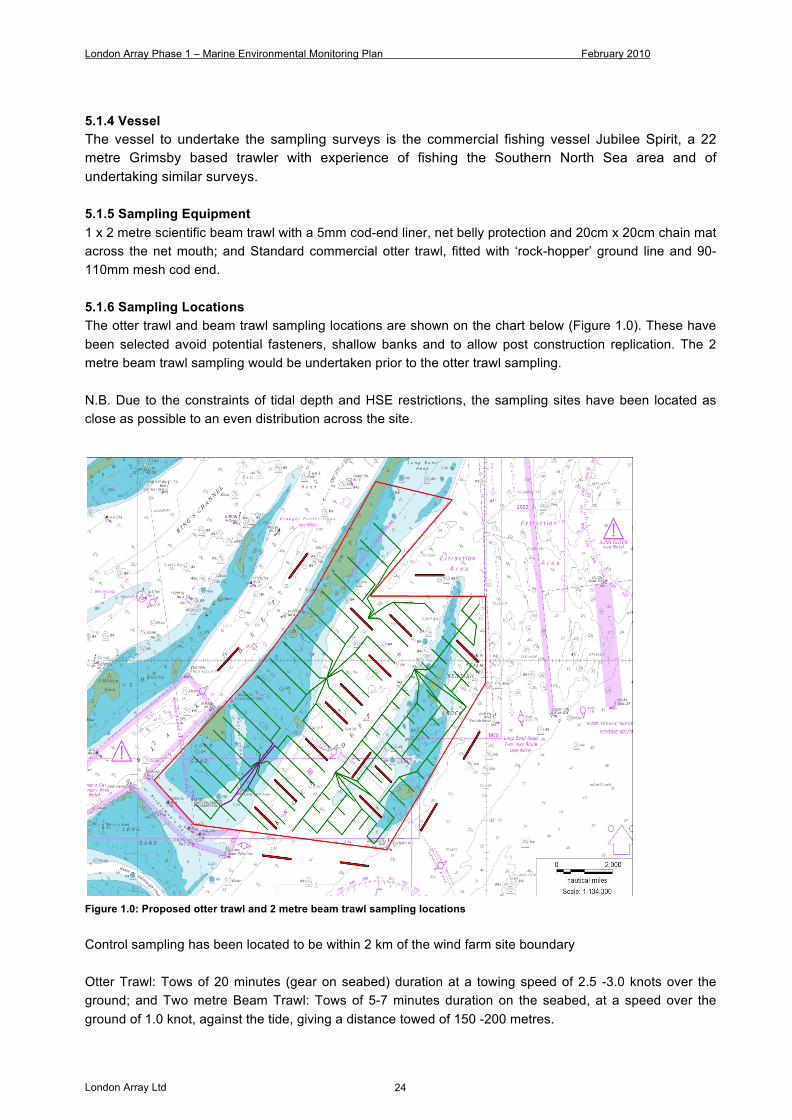
5.1.4 Vessel The vessel to undertake the sampling surveys is the commercial fishing vessel Jubilee Spirit, a 22 metre Grimsby based trawler with experience of fishing the Southern North Sea area and of undertaking similar surveys. 5.1.5 Sampling Equipment 1 x 2 metre scientific beam trawl with a 5mm cod-end liner, net belly protection and 20cm x 20cm chain mat across the net mouth; and Standard commercial otter trawl, fitted with ‘rock-hopper’ ground line and 90-110mm mesh cod end. 5.1.6 Sampling Locations The otter trawl and beam trawl sampling locations are shown on the chart below (Figure 1.0). These have been selected avoid potential fasteners, shallow banks and to allow post construction replication. The 2 metre beam trawl sampling would be undertaken prior to the otter trawl sampling. N.B. Due to the constraints of tidal depth and HSE restrictions, the sampling sites have been located as close as possible to an even distribution across the site.
Figure 1.0: Proposed otter trawl and 2 metre beam trawl sampling locations Control sampling has been located to be within 2 km of the wind farm site boundary Otter Trawl: Tows of 20 minutes (gear on seabed) duration at a towing speed of 2.5 -3.0 knots over the ground; and Two metre Beam Trawl: Tows of 5-7 minutes duration on the seabed, at a speed over the ground of 1.0 knot, against the tide, giving a distance towed of 150 -200 metres.
London Array Phase 1 – Marine Environmental Monitoring Plan February 2010
London Array Ltd 25
5.1.7 - Sample Preservation 2 metre beam trawl samples preserved in 4% formalin seawater buffered; and Otter trawl samples boxed and ices and stored at +2°C. 5.1.8 - Sample Analysis The otter trawl samples would be analysed at the CEFAS Laboratory, Lowestoft, as follows:
• Number by species • Sex ratio, samples of principal commercial species • Spawning condition by species • Length distribution by species • Finfish: total individual lengths to cm below • Crabs: carapace width • Lobsters: carapace length • Whelks: shell height • Scallops: shell width
Cephalopods and other bivalves will be recorded and measured where feasible. The 2 metre beam trawl samples would be identified and where appropriate length and condition would be recorded. 5.1.9 - Reporting A short illustrated report will be produced for each sampling event. This will provide an outline of the methodology employed and any problems encountered and consequential on site amendments to the methodology, and sub-sampling employed. The results section will provide a detailed field log listing the details as per section 5. This section will also include all fish species encountered, the number of each species, lengths, sex and maturity of elasmobranch species. Photographs and graphically representations using Excel and GIS will be used where appropriate to illustrate this report. For ongoing surveys, the discussion section will provide brief comparisons to previous fish sampling events. The monitoring report will be forwarded to the Licensing Authority within three months of the completion of the analyses. London Array will advise the Licensing Authority if circumstances suggest that there will be a delay in the submission of the report.
London Array Phase 1 – Marine Environmental Monitoring Plan February 2010
London Array Ltd 26
6.1 - Review of Electromagnetic Fields 6.1.1 - Need for Survey The exact wording within FEPA consent 32945/07/2 that states the requirement to undertake an electro-magnetic field survey is provided below.
Relevant FEPA Consent Clause(s)
Description
Annex 1 – Point 6
The Licence Holder must provide the Licensing Authority with information on at-tenuation of field strengths associated with the cables, shielding and burial de-scribed in the Method Statement and relate these to any outputs from the COWRIE sponsored studies in the UK. This is to provide reassurance that the cable shielding and burial depth(s), given the sediment type, at the site is sufficient to ensure that the electromagnetic field generated is negligible. Should this study show that the field strengths associated with the cables are sufficient to have a potentially detri-mental effect on electrosensitive species, further biological monitoring and mitiga-tion may be required to further investigate the effect.
6.1.2 - Reporting In order to satisfy this licence condition, the Licence Holder will prepare a short technical note on electromagnetic field effects 4 months before pre-construction has commenced.


![[Array, Array, Array, Array, Array, Array, Array, Array, Array, Array, Array, Array]](https://img.pdfslide.net/doc/110x75/56816460550346895dd63b8b/array-array-array-array-array-array-array-array-array-array-array.jpg)