Embed Size (px)
Citation preview

Precipitation during Tempering of Martensite in Fe-Cr-C alloys
CHANACHON TECHABOONANEK
Master of Science Thesis
Stockholm, Sweden 2012
Precipitation during Tempering of
Martensite in Fe-Cr-C alloys
Chanachon Techaboonanek
Masters Degree Project
hero-m
KTH School of Industrial Engineering and Management
Department of Materials Science and Engineering
SE-100 44 Stockholm Sweden
September 2012
ABSTRACT
The martensite structure is the most important microstructure in tool steel due to its high hardness.
However, a lack of ductility is the major drawback. In order to improve the ductility and still
maintaining a suitable hardness a tempering process is needed. The tempering process will cause
recovery and recrystallization in the matrix, and moreover carbides will precipitate. The specific
carbides have different characteristics and thus the type of carbide formed during tempering is very
important for the properties of the steel. The simulation software (TC-Prisma) is interesting because
it can predict type, size, and amount of carbides. The present study was carried out to investigate
both the microstructure, hardness evolution of martensite and precipitation which occurred in Fe-C-
Cr steel with different compositions, tempered at 700oC. The experimental results were compared
with simulation results. Micro-Vickers hardness test with a load of 100 g was used and the hardness
value dropped 40% and 60% in low carbon alloy and high carbon alloy steels, respectively. The
significant drop occurred during the first 30 seconds of tempering due to recovery of the matrix.
Hardness values slightly decreased and then stabilized during continued tempering. The
microstructure of martensite and the morphology of carbides at different tempering times were
examined by scanning and transmission electron microscopy in order to study the precipitation of
carbides from the nucleation and growth to coarsening. There are three types of carbides which
precipitated in the Fe-C-Cr specimens: M7C3, cementite and M3C2 depending on the composition. Fe-
0.16C-4.05Cr contained M7C3, Fe-0.95C-1.065Cr contained cementite and M3C2 and Fe-014C-0.983Cr
and Fe-0.88C-4.12Cr contained M7C3 and cementite. M7C3 has a faceted shape and precipitates
referentially at grain boundaries. On the other hand, cementite has an elongated shape and
precipitated mainly at grain boundaries but also intragranulary. M3C2 has a rounded shape and was
seen only in very small amounts, and seemed to precipitate at random sites. The trend of carbide
growth in experiments is consistent with the simulations using TC-Prisma, but more work is needed
to enable quantitative comparisons.
Key words: precipitation, microstructure, tempered martensite, Fe-C-Cr alloys, carbide, simulation
1
Contents
1. Introduction ......................................................................................................................................... 2
1.1 Scope of the work .......................................................................................................................... 2
2. Theory and Background....................................................................................................................... 3
2.1 Martensite ..................................................................................................................................... 3
2.1.1 Martensite in the Fe-Cr-C system ........................................................................................... 4
2.2 Quenching and tempering ............................................................................................................. 5
2.2 Carbides in Fe-Cr-C system ............................................................................................................ 6
2.3 Particle analysis software .............................................................................................................. 7
2.4 Simulations .................................................................................................................................... 8
3. Materials and experimental methods ................................................................................................. 9
3.1 Micro hardness testing ................................................................................................................ 10
4. Results ............................................................................................................................................... 11
4.1 Microstructures ........................................................................................................................... 11
4.2 Particle size and size distribution curves ..................................................................................... 18
4.3 Micro hardness ............................................................................................................................ 21
4.4 Simulations .................................................................................................................................. 23
5. Discussion .......................................................................................................................................... 26
5.1 Precipitates in Fe-Cr-C ................................................................................................................. 26
5.2 Comparison between experiments and simulations ................................................................... 27
5.3 Evolution of mechanical properties ............................................................................................ 28
6. Conclusions ........................................................................................................................................ 29
7. Future work ....................................................................................................................................... 29
8. Acknowledgements ........................................................................................................................... 30
9. References ......................................................................................................................................... 31

2
1. Introduction
Tool steels are alloyed steels which are used to machine other materials. One important property of
tool steels is high hardness. High hardness is needed to increase the wear resistance during
operation. The properties of tool steels are the consequences of the alloying elements and the heat
treatment process during production. Quenching of the steel from high temperature will transform
the austenite Face Centered Cubic structure (FCC) into carbon supersaturated Body Centered
Tetragonal structure (BCT), called “martensite”. The martensite structure is hard and brittle. The
brittle nature is a serious disadvantage of the martensite structure and in order to improve the
toughness an additional heat treatment called tempering is required. This treatment can relieve
stresses which are generated during the quenching process. In addition secondary carbides may
precipitate. The structure after tempering is called tempered martensite.
Common alloying elements in tool steels are chromium, vanadium, and molybdenum. These alloying
elements will affect the martensite start temperature which can give a different type of martensite
structure but also affect the precipitation of carbide [1-4]. Chromium as an alloying element can
improve hardenability, resistance to deformation and cracking during a high temperature operation.
These properties are important for specific tool steels and thus, the iron chromium carbon system
with additional elements is normally used as tool steels [5]. The main problem during tempering of
martensite is over-aging. Over-aging leads to coarsening of the carbides and too large particle sizes
will harm the properties, such as hardness, of the tool steels. Proper control of the carbide size and
the amount is thus vital.
TC-Prisma is a software program that can simulate the precipitation of carbides during tempering of
martensite and it is based on available thermodynamic and kinetic descriptions [6]. TC-Prisma can
simulate and predict type, size distribution, and amount of precipitates based on thermodynamic and
kinetic data with some additional parameter input. Successful predictions in TC-Prisma may
considerably limit the amount of experiments needed.
1.1 Scope of the work
The aim of the present thesis is to investigate tempering of martensite in alloy steel. Four Fe-Cr-C
alloys with different compositions of carbon and chromium were used in the present work. Solution
treatment followed by quenching and tempering were conducted and the structure was evaluated
using Scanning electron microscopy (SEM). Image analysis was performed to measure amount,
shape, average diameter, and size distribution of different carbides. The results were compared with
simulations in TC-Prisma.
3
2. Theory and Background
2.1 Martensite
The martensitic transformation in Fe-C-based alloys occurs when the material is rapidly cooled from
a temperature above the lower transformation temperature (A1). This process is called quenching
and there is no diffusion involved in this process. The quenching results in a change of crystal
structure from FCC to BCT. Higher carbon content gives more tetragonal martensite structure [7].
The martensite structure starts to form at the martensite start temperature (Ms) and continue to
form in a specific temperature interval. The type of martensite formed can be predicted from alloy
composition. There are many types of morphologies, for example lath and plate martensite.
Sometimes, retained austenite is also found after quenching [8].
The change in Ms temperature due to alloying elements affects morphology and the
properties of martensite. The effect of alloying elements on the Ms temperature is shown in
equation 1 [9]. The decrease in Ms temperature may be caused by the entering of the alloying
element into solid solution of austenite, and interstitials such as carbon and nitrogen will give a much
higher effect than substitutional elements [10].
(1)
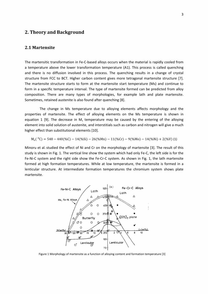
Minoru et al. studied the effect of Ni and Cr on the morphology of martensite [3]. The result of this
study is shown in Fig. 1. The vertical line show the system which had only Fe-C, the left side is for the
Fe-Ni-C system and the right side show the Fe-Cr-C system. As shown in Fig. 1, the lath martensite
formed at high formation temperatures. While at low temperature, the martensite is formed in a
lenticular structure. At intermediate formation temperatures the chromium system shows plate
martensite.
Figure 1 Morphology of martensite as a function of alloying content and formation temperature [3]
4
There are many factors that can control the martensite morphology:
Ms temperature
Austenite stacking fault energy
Driving force involved in the transformation to martensite
Critical resolved shear stress for slip and twinning martensite.
All of these factors are very difficult to investigate separately.
2.1.1 Martensite in the Fe-Cr-C system
Chromium (Cr) is one of the elements which decrease the stacking fault energy of
austenite [3]. The morphology of Fe-Cr-C steel can be divided into many types, depending on the
composition of chromium and carbon (mass %). The morphology of Fe-Cr-C martensite with the same
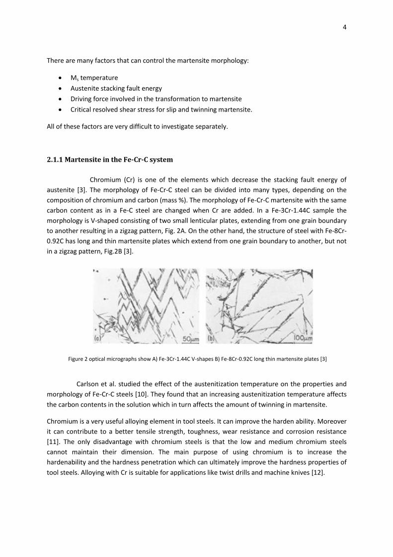
carbon content as in a Fe-C steel are changed when Cr are added. In a Fe-3Cr-1.44C sample the
morphology is V-shaped consisting of two small lenticular plates, extending from one grain boundary
to another resulting in a zigzag pattern, Fig. 2A. On the other hand, the structure of steel with Fe-8Cr-
0.92C has long and thin martensite plates which extend from one grain boundary to another, but not
in a zigzag pattern, Fig.2B [3].
Carlson et al. studied the effect of the austenitization temperature on the properties and
morphology of Fe-Cr-C steels [10]. They found that an increasing austenitization temperature affects
the carbon contents in the solution which in turn affects the amount of twinning in martensite.
Chromium is a very useful alloying element in tool steels. It can improve the harden ability. Moreover
it can contribute to a better tensile strength, toughness, wear resistance and corrosion resistance
[11]. The only disadvantage with chromium steels is that the low and medium chromium steels
cannot maintain their dimension. The main purpose of using chromium is to increase the
hardenability and the hardness penetration which can ultimately improve the hardness properties of
tool steels. Alloying with Cr is suitable for applications like twist drills and machine knives [12].
Figure 2 optical micrographs show A) Fe-3Cr-1.44C V-shapes B) Fe-8Cr-0.92C long thin martensite plates [3]
5
2.2 Quenching and tempering
Hardening or quenching of carbon steels is the process of getting a martensite structure in
order to increase the yield strength in the material. It depends on the dissolved carbon content in
austenite. In selecting suitable conditions for hardening the risk of cracking should be kept in mind.
The cracking is caused by [9]:
The steel composition: the lower in Ms temperature, the higher risk of cracking.
The shape of the product: especially at the corner and the edge. If there is a big difference in
the thickness or cross section area, it is likely to initiate cracking.
The heat treatment process: quenching from a high austenite temperature will increase the
stress in a product and induce cracking in the material.
Another important factor which can affect the martensite structure is quenching medium. The
selection of a quench medium is dictated by the necessary cooling rate to achieve full hardness
without cracking of the work piece, for example a low carbon steel needs a fast cooling rate while a
high-alloy steel can use a slow cooling rate. Four types of quenching media are commonly used
water, brine, oil, and polymer. Each quenching medium has its own advantage and disadvantage. The
advantage with brine with sodium chloride 10 %, and sodium hydroxide 3% is a very high cooling rate
compared to water and that no dangerous residues are formed. The mechanism of cooling by brine
starts with salt crystal depositing on the surface of the specimen. These crystals break and hinder the
formation of a vapor film. Then, the liquid can easily transfer a lot of heat from the specimen. The
disadvantage with brine is that it consists of salt which can cause corrosion in some steels, so a
cleaning process after quenching is needed [13].
Tempering is a process of heat treatment to relieve the stresses generated by the
hardening and results in an increased ductility and toughness [12]. The processes which occur during
the tempering are recrystallization and precipitation [13].
The different precipitation reactions and other processes occurring during tempering of martensite in
Fe-C based alloys have been studied in detail by many authors. According to Speich et al. [15-16] at
100-250oC, formation of a transition carbide occurs while the carbon content decreases in the
martensite structure. The second stage occurs at temperatures between 200-300oC: retained
austenite transforms to ferrite and cementite and orthorhombic M3C carbide form. This usually
occurs in low-alloy steels. In high alloy steels the latter step may not occur since the austenite is
stable and the decomposition does not occur during a conventional tempering treatment. The third
stage is between 250-700oC and is associated with the precipitation of Fe3C and cementite in
martensite. Many thermally activated processes occur in this step for example recovery,
recrystallization, and grain growth. The final structure was an equiaxed ferrite containing a coarse
dispersion of spheroidal cementite particles. Another stage for steel which contain strong carbide
formers such as chromium, tungsten and molybdenum occurs between 500-700oC. Cementite
particles dissolve and are replaced by more stable and finer dispersion of alloy carbides [16]. This
step which can significantly increase the hardness of the steel is called secondary hardening.
6
2.2 Carbides in Fe-Cr-C system
The characteristics of the tempered martensitic steels can be determined by shape, size,
composition, and the distribution of formed carbides. The carbides that precipitate in the Fe-Cr-C
tools steels, such as M3C, M23C6, M6C, and M7C3 can be predicted by the Pseudo-binary phase
diagram which is calculated from the Thermo-Calc software. To predict the types of carbide in the Fe-
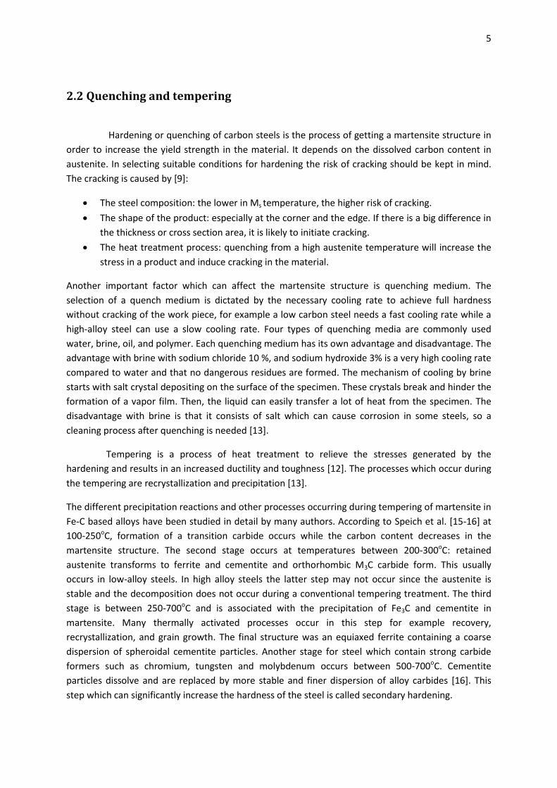
Cr-C tool steels at tempering temperature 700oC, the Pseudo phase diagram was used. The phase
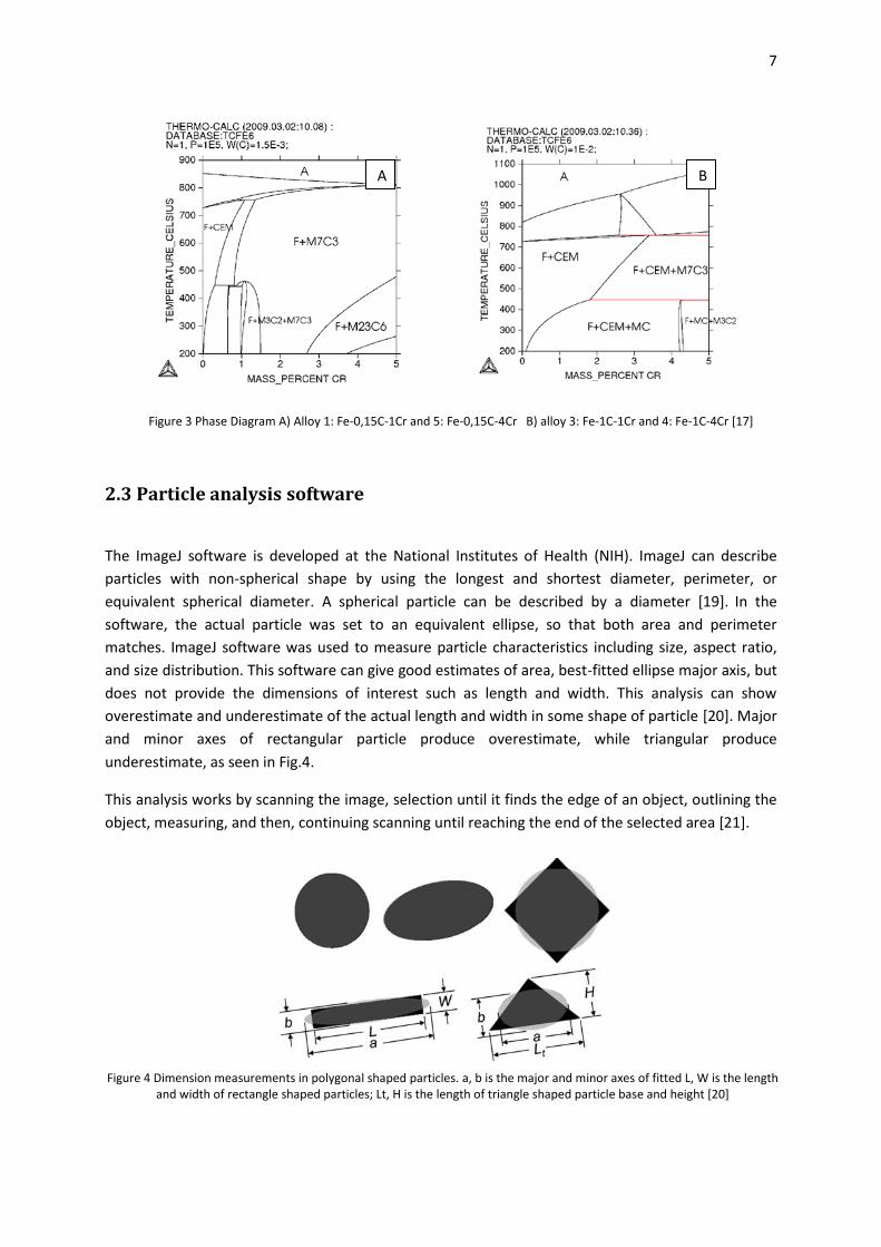
diagram in Fig.3A is for low carbon 0.15 mass% and Fig.3B is for high carbon 1 mass% [17]. Prabhudev
[18] studied the favorable condition and types of carbides. They showed that the favorable condition
for precipitation of carbides during the tempering is at saturation of austenite with the carbide
forming element such as chromium, vanadium, or tungsten. The quantity of carbides is related to the
amount of the carbon, the alloying element and the type of formed carbide. Carbides which are
represented in this phase diagram are Cementite and M7C3 carbide. Usually hardness of Cementite
(M3C) is around 910 and 1050HV and the lattice is Orthorhombic. Another precipitate is complex
chromium carbide (M7C3) which was found present in steel that had chromium more than 3-4% or
0.8-1.1% carbon. The lattice type is a hexagonal and the hardness is around 1600-1800HV. These
carbides have high hardness which can increase the wear resistance and stability, but decrease the
friction coefficient.
There are three types of nucleation sites for alloy carbides [10]:
In-situ: nucleation at pre-existing cementite particles which are located at interfaces
between ferrite and cementite.
Separate: nucleation on dislocations retained from the martensite structure.
Grain boundaries and sub-grain boundaries: lath boundaries, prior austenite grain
boundaries or recrystallized grains.
In steels with more than 4 mass% Cr, Fe3C transformed to M7C3 mainly at the interfaces of ferrite and
Fe3C [16].
There are many methods to classify the types of carbides. One method is the extraction
carbon replication technique, which was used in [10] in order to determine the size, number and
type of particles. To determine types of particle, diffraction pattern analysis was employed. Some
researchers develop their own etching solutions to get the best result. For example, Yuehui et al. [8]
developed an etching solution suitable for low carbon steels by mixing 6% HNO3 with saturated picric
acid in an alcohol.
7
2.3 Particle analysis software
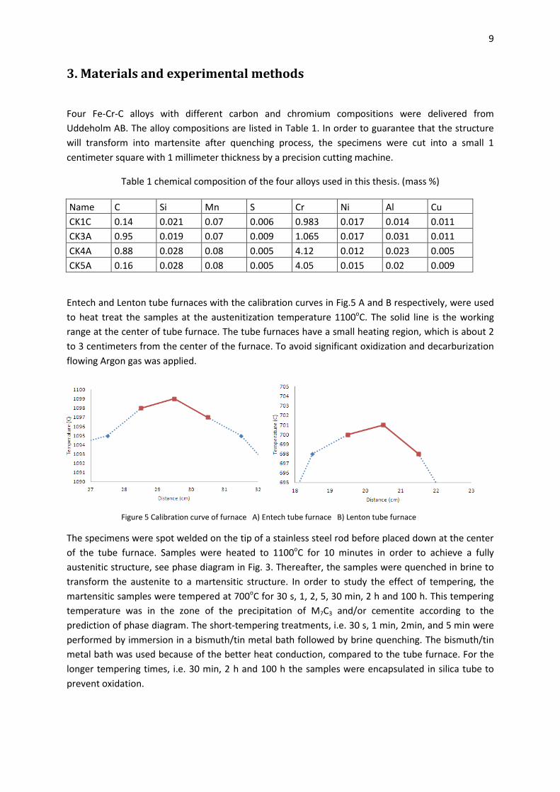
The ImageJ software is developed at the National Institutes of Health (NIH). ImageJ can describe
particles with non-spherical shape by using the longest and shortest diameter, perimeter, or
equivalent spherical diameter. A spherical particle can be described by a diameter [19]. In the
software, the actual particle was set to an equivalent ellipse, so that both area and perimeter
matches. ImageJ software was used to measure particle characteristics including size, aspect ratio,
and size distribution. This software can give good estimates of area, best-fitted ellipse major axis, but
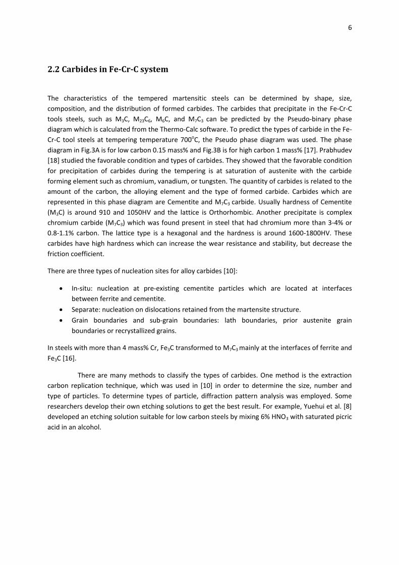
does not provide the dimensions of interest such as length and width. This analysis can show
overestimate and underestimate of the actual length and width in some shape of particle [20]. Major
and minor axes of rectangular particle produce overestimate, while triangular produce
underestimate, as seen in Fig.4.
This analysis works by scanning the image, selection until it finds the edge of an object, outlining the
object, measuring, and then, continuing scanning until reaching the end of the selected area [21].
A B
Figure 3 Phase Diagram A) Alloy 1: Fe-0,15C-1Cr and 5: Fe-0,15C-4Cr B) alloy 3: Fe-1C-1Cr and 4: Fe-1C-4Cr [17]
Figure 4 Dimension measurements in polygonal shaped particles. a, b is the major and minor axes of fitted L, W is the length and width of rectangle shaped particles; Lt, H is the length of triangle shaped particle base and height [20]

8
2.4 Simulations
TC-Prisma is a software package which treats concurrent nucleation, growth (dissolution) and
coarsening under isothermal conditions in multi-component and multi-phase systems by using the
Langer-Schwartz theory and the Kampmann-Wagner numerical approach [6].The nucleation model
implemented into this software accounts for heterogeneous nucleation and several different types of
nucleation sites are considered. To ensure high predictive capabilities thermodynamic, kinetic and
property databases assessed by the CALPHAD method are used for calculating diffusivities and
surface energies. The Gibbs-Thomson is taken into account during the calculation in order to predict
and model phase transformations. Some of the features in TC-Prisma are:
•Handling of concurrent nucleation, growth/dissolution and coarsening of precipitates
•Simulation of the temporal evolution of particle size distributions
•Calculation of average radius, number density, volume fraction and composition of precipitates
•Extraction of nucleation and coarsening rate
•Calculation of Time-Temperature-Precipitation (TTP) diagrams
9
3. Materials and experimental methods
Four Fe-Cr-C alloys with different carbon and chromium compositions were delivered from
Uddeholm AB. The alloy compositions are listed in Table 1. In order to guarantee that the structure
will transform into martensite after quenching process, the specimens were cut into a small 1
centimeter square with 1 millimeter thickness by a precision cutting machine.
Table 1 chemical composition of the four alloys used in this thesis. (mass %)
Name C Si Mn S Cr Ni Al Cu
CK1C 0.14 0.021 0.07 0.006 0.983 0.017 0.014 0.011
CK3A 0.95 0.019 0.07 0.009 1.065 0.017 0.031 0.011
CK4A 0.88 0.028 0.08 0.005 4.12 0.012 0.023 0.005
CK5A 0.16 0.028 0.08 0.005 4.05 0.015 0.02 0.009
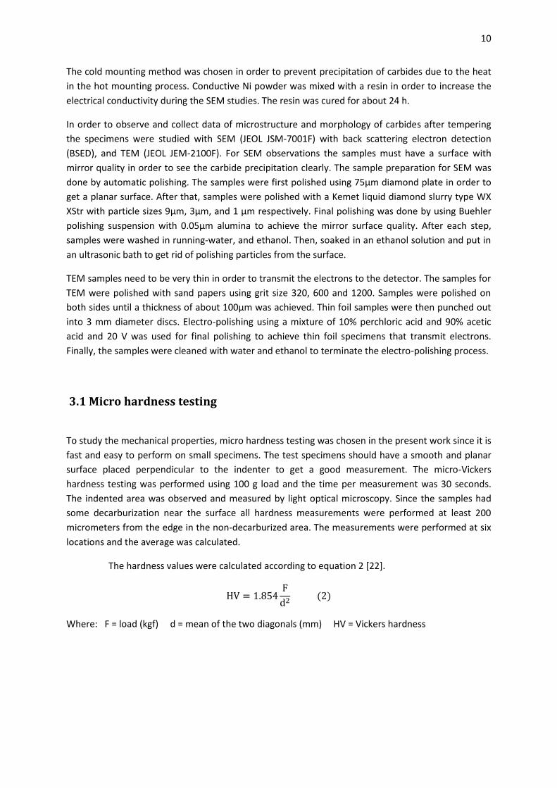
Entech and Lenton tube furnaces with the calibration curves in Fig.5 A and B respectively, were used
to heat treat the samples at the austenitization temperature 1100oC. The solid line is the working
range at the center of tube furnace. The tube furnaces have a small heating region, which is about 2
to 3 centimeters from the center of the furnace. To avoid significant oxidization and decarburization
flowing Argon gas was applied.
The specimens were spot welded on the tip of a stainless steel rod before placed down at the center
of the tube furnace. Samples were heated to 1100oC for 10 minutes in order to achieve a fully
austenitic structure, see phase diagram in Fig. 3. Thereafter, the samples were quenched in brine to
transform the austenite to a martensitic structure. In order to study the effect of tempering, the
martensitic samples were tempered at 700oC for 30 s, 1, 2, 5, 30 min, 2 h and 100 h. This tempering
temperature was in the zone of the precipitation of M7C3 and/or cementite according to the
prediction of phase diagram. The short-tempering treatments, i.e. 30 s, 1 min, 2min, and 5 min were
performed by immersion in a bismuth/tin metal bath followed by brine quenching. The bismuth/tin
metal bath was used because of the better heat conduction, compared to the tube furnace. For the
longer tempering times, i.e. 30 min, 2 h and 100 h the samples were encapsulated in silica tube to
prevent oxidation.
A B
Figure 5 Calibration curve of furnace A) Entech tube furnace B) Lenton tube furnace
10
The cold mounting method was chosen in order to prevent precipitation of carbides due to the heat
in the hot mounting process. Conductive Ni powder was mixed with a resin in order to increase the
electrical conductivity during the SEM studies. The resin was cured for about 24 h.
In order to observe and collect data of microstructure and morphology of carbides after tempering
the specimens were studied with SEM (JEOL JSM-7001F) with back scattering electron detection
(BSED), and TEM (JEOL JEM-2100F). For SEM observations the samples must have a surface with
mirror quality in order to see the carbide precipitation clearly. The sample preparation for SEM was
done by automatic polishing. The samples were first polished using 75µm diamond plate in order to
get a planar surface. After that, samples were polished with a Kemet liquid diamond slurry type WX
XStr with particle sizes 9µm, 3µm, and 1 µm respectively. Final polishing was done by using Buehler
polishing suspension with 0.05µm alumina to achieve the mirror surface quality. After each step,
samples were washed in running-water, and ethanol. Then, soaked in an ethanol solution and put in
an ultrasonic bath to get rid of polishing particles from the surface.
TEM samples need to be very thin in order to transmit the electrons to the detector. The samples for
TEM were polished with sand papers using grit size 320, 600 and 1200. Samples were polished on
both sides until a thickness of about 100µm was achieved. Thin foil samples were then punched out
into 3 mm diameter discs. Electro-polishing using a mixture of 10% perchloric acid and 90% acetic
acid and 20 V was used for final polishing to achieve thin foil specimens that transmit electrons.
Finally, the samples were cleaned with water and ethanol to terminate the electro-polishing process.
3.1 Micro hardness testing
To study the mechanical properties, micro hardness testing was chosen in the present work since it is
fast and easy to perform on small specimens. The test specimens should have a smooth and planar
surface placed perpendicular to the indenter to get a good measurement. The micro-Vickers
hardness testing was performed using 100 g load and the time per measurement was 30 seconds.
The indented area was observed and measured by light optical microscopy. Since the samples had
some decarburization near the surface all hardness measurements were performed at least 200
micrometers from the edge in the non-decarburized area. The measurements were performed at six
locations and the average was calculated.
The hardness values were calculated according to equation 2 [22].
Where: F = load (kgf) d = mean of the two diagonals (mm) HV = Vickers hardness
11
4. Results
4.1 Microstructures
The microstructures of as-quenched, 30 seconds, 2 minutes, 30 minutes, 2 and 100 h samples were
studied in the SEM. The as-quenched microstructure was selected to be the reference structure for
each condition. Specimens at 30 s, and 2 min were selected for studies on the microstructure after
short time aging which is related to the significant hardness drop seen in the alloys. The
microstructures at 30 min and 2 h were selected to be the microstructure of intermediate aging time
and the 100 h sample was selected to be the microstructure after long aging times in the alloys.
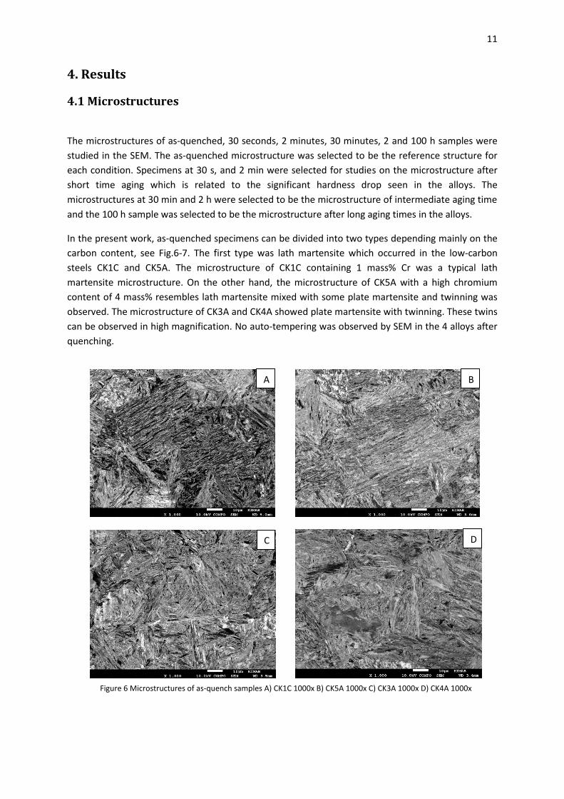
In the present work, as-quenched specimens can be divided into two types depending mainly on the
carbon content, see Fig.6-7. The first type was lath martensite which occurred in the low-carbon
steels CK1C and CK5A. The microstructure of CK1C containing 1 mass% Cr was a typical lath
martensite microstructure. On the other hand, the microstructure of CK5A with a high chromium
content of 4 mass% resembles lath martensite mixed with some plate martensite and twinning was
observed. The microstructure of CK3A and CK4A showed plate martensite with twinning. These twins
can be observed in high magnification. No auto-tempering was observed by SEM in the 4 alloys after
quenching.
D
B
C
A
Figure 6 Microstructures of as-quench samples A) CK1C 1000x B) CK5A 1000x C) CK3A 1000x D) CK4A 1000x
12
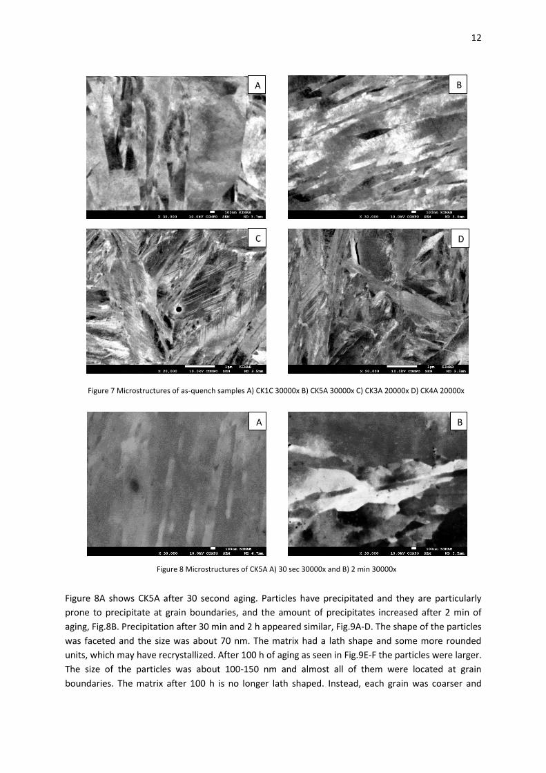
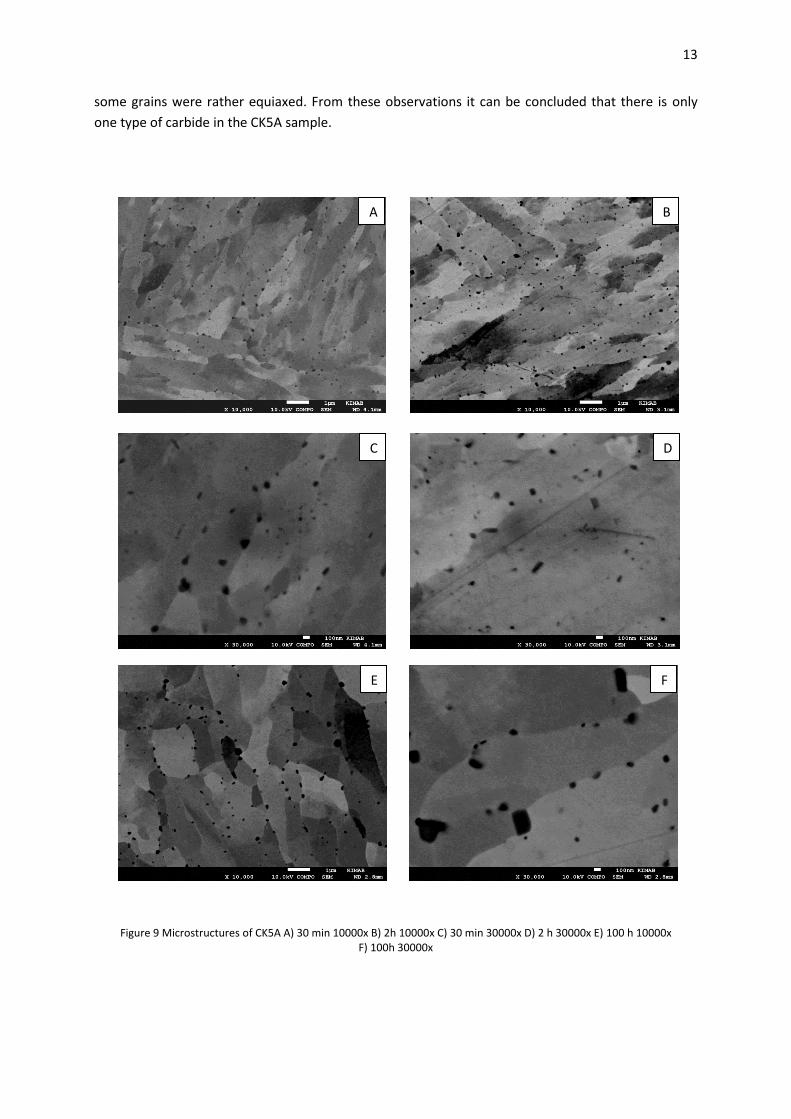
Figure 8A shows CK5A after 30 second aging. Particles have precipitated and they are particularly
prone to precipitate at grain boundaries, and the amount of precipitates increased after 2 min of
aging, Fig.8B. Precipitation after 30 min and 2 h appeared similar, Fig.9A-D. The shape of the particles
was faceted and the size was about 70 nm. The matrix had a lath shape and some more rounded
units, which may have recrystallized. After 100 h of aging as seen in Fig.9E-F the particles were larger.
The size of the particles was about 100-150 nm and almost all of them were located at grain
boundaries. The matrix after 100 h is no longer lath shaped. Instead, each grain was coarser and
C
A
D
B
C
A
Figure 7 Microstructures of as-quench samples A) CK1C 30000x B) CK5A 30000x C) CK3A 20000x D) CK4A 20000x
B A
Figure 8 Microstructures of CK5A A) 30 sec 30000x and B) 2 min 30000x
13
some grains were rather equiaxed. From these observations it can be concluded that there is only
one type of carbide in the CK5A sample.
Figure 9 Microstructures of CK5A A) 30 min 10000x B) 2h 10000x C) 30 min 30000x D) 2 h 30000x E) 100 h 10000x F) 100h 30000x
D C
B
E
A
F
14
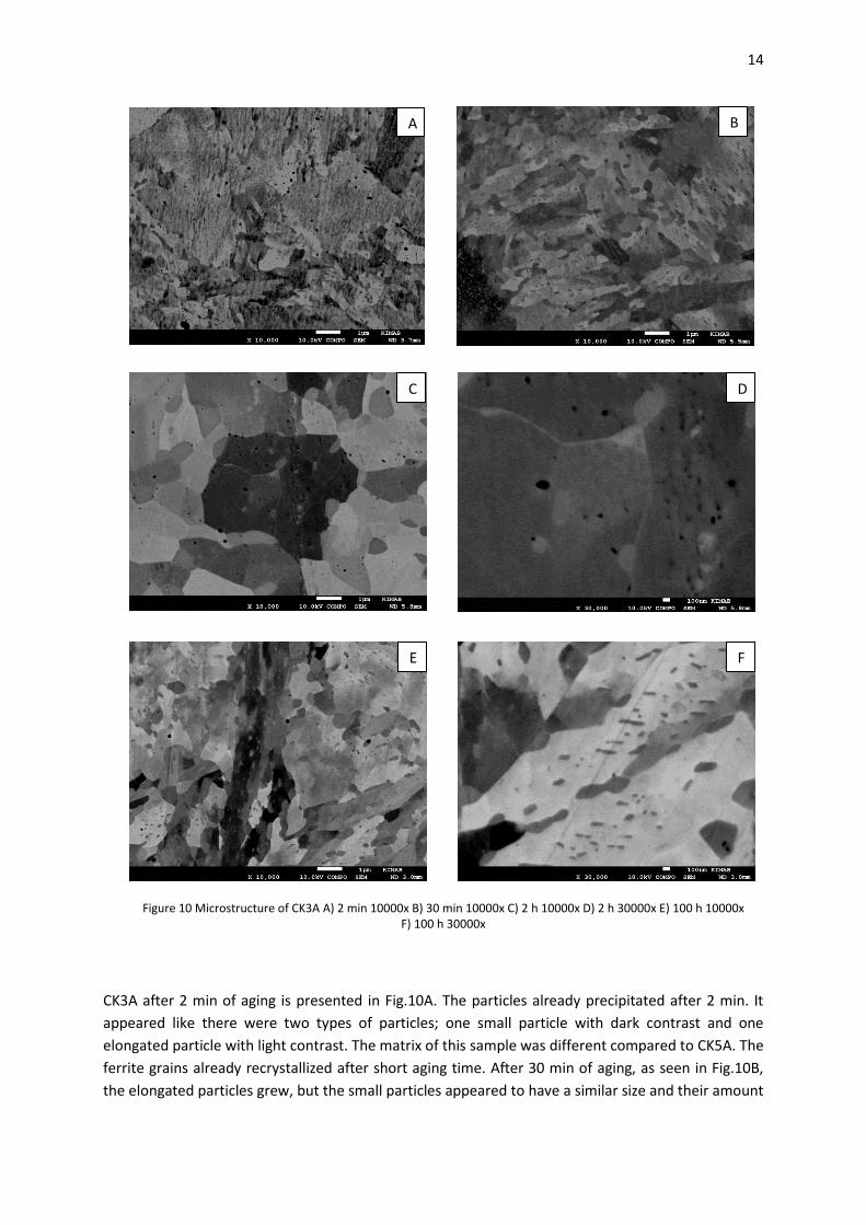
CK3A after 2 min of aging is presented in Fig.10A. The particles already precipitated after 2 min. It
appeared like there were two types of particles; one small particle with dark contrast and one
elongated particle with light contrast. The matrix of this sample was different compared to CK5A. The
ferrite grains already recrystallized after short aging time. After 30 min of aging, as seen in Fig.10B,
the elongated particles grew, but the small particles appeared to have a similar size and their amount
D
B
C
A
F E
Figure 10 Microstructure of CK3A A) 2 min 10000x B) 30 min 10000x C) 2 h 10000x D) 2 h 30000x E) 100 h 10000x F) 100 h 30000x
15
also decreased compared to the short aging time. After 2 h of aging, as seen in Fig.10C-D, the size of
the small particles decreased and they were hardly found in the matrix. On the other hand the
elongated particles had grown and they were clearly seen at grain boundaries and inside grains. The
matrix grains were larger after 2 h of aging. After 100 h aging, as seen in Fig.10E-F, the matrix was no
longer plate shaped. It transformed to ferrite grains with diameter of about 1.5-2 µm. The size of the
elongated particles are about 400-500 nm. The size of the small particle seemed to be the same, but
the amount had decreased. From these observations it can be concluded that there are two types of
carbides in CK3A.
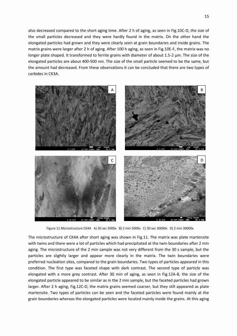
The microstructure of CK4A after short aging was shown in Fig.11. The matrix was plate martensite
with twins and there were a lot of particles which had precipitated at the twin boundaries after 2 min
aging. The microstructure of the 2 min sample was not very different from the 30 s sample, but the
particles are slightly larger and appear more clearly in the matrix. The twin boundaries were
preferred nucleation sites, compared to the grain boundaries. Two types of particles appeared in this
condition. The first type was faceted shape with dark contrast. The second type of particle was
elongated with a more grey contrast. After 30 min of aging, as seen in Fig.12A-B, the size of the
elongated particle appeared to be similar as in the 2 min sample, but the faceted particles had grown
larger. After 2 h aging, Fig.12C-D, the matrix grains seemed coarser, but they still appeared as plate
martensite. Two types of particles can be seen and the faceted particles were found mainly at the
grain boundaries whereas the elongated particles were located mainly inside the grains. At this aging
A
C
D
B A
C
Figure 11 Microstructure CK4A A) 30 sec 5000x B) 2 min 5000x C) 30 sec 30000x D) 2 min 30000x
16
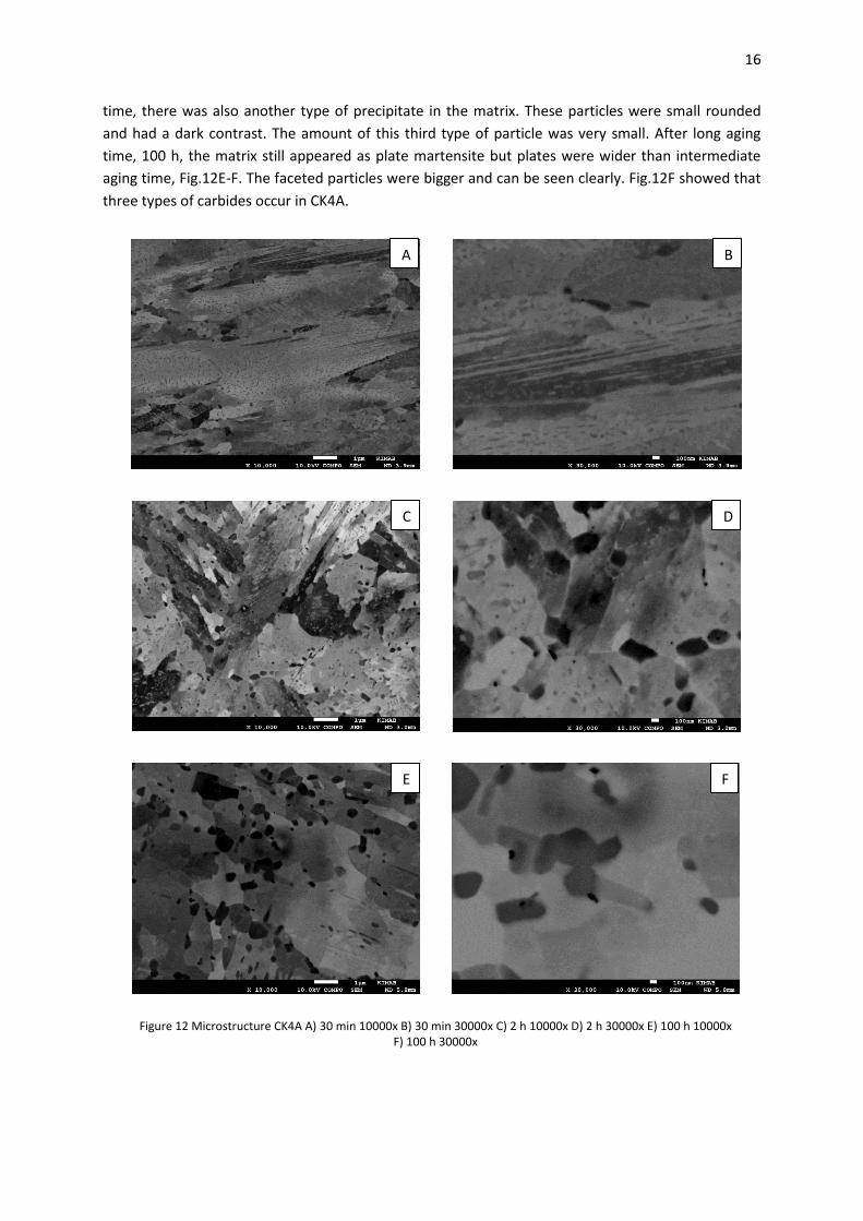
time, there was also another type of precipitate in the matrix. These particles were small rounded
and had a dark contrast. The amount of this third type of particle was very small. After long aging
time, 100 h, the matrix still appeared as plate martensite but plates were wider than intermediate
aging time, Fig.12E-F. The faceted particles were bigger and can be seen clearly. Fig.12F showed that
three types of carbides occur in CK4A.
D
B
C
A
F E
Figure 12 Microstructure CK4A A) 30 min 10000x B) 30 min 30000x C) 2 h 10000x D) 2 h 30000x E) 100 h 10000x F) 100 h 30000x
17
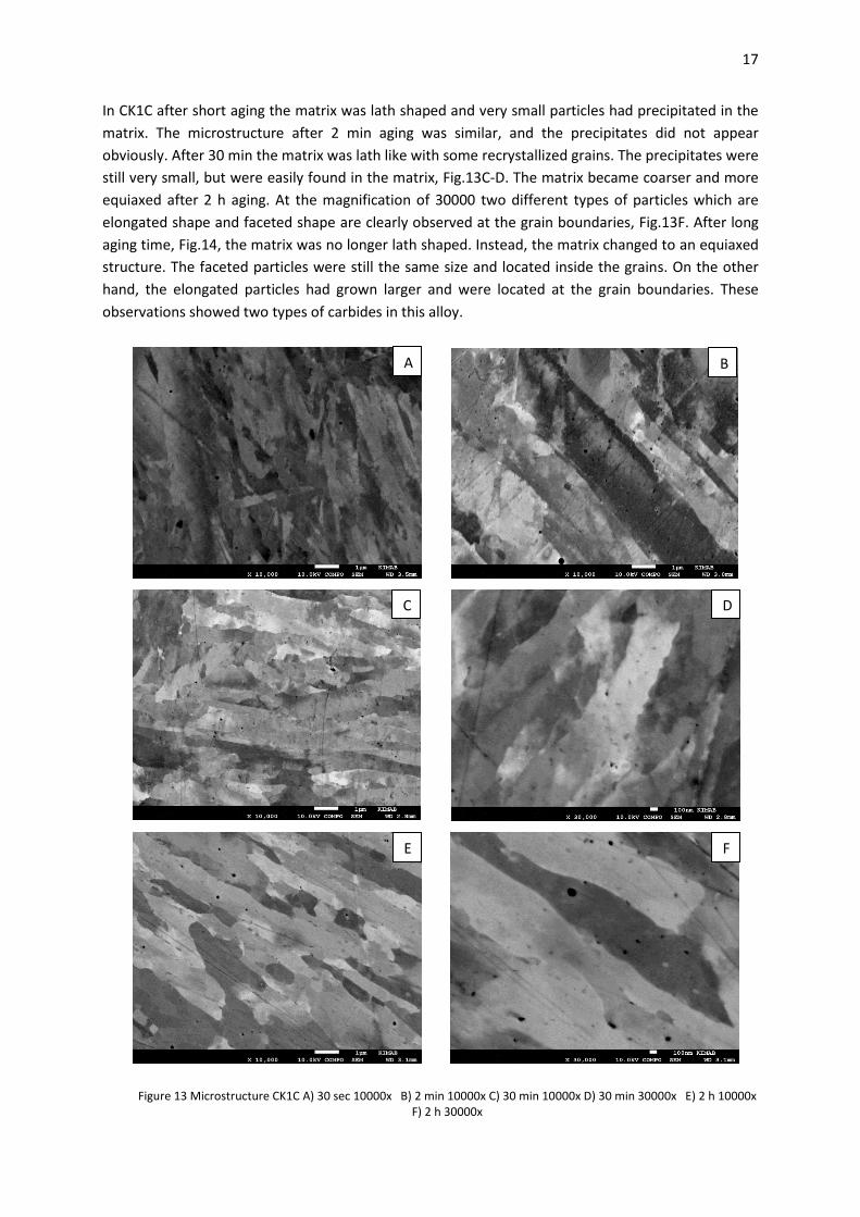
In CK1C after short aging the matrix was lath shaped and very small particles had precipitated in the
matrix. The microstructure after 2 min aging was similar, and the precipitates did not appear
obviously. After 30 min the matrix was lath like with some recrystallized grains. The precipitates were
still very small, but were easily found in the matrix, Fig.13C-D. The matrix became coarser and more
equiaxed after 2 h aging. At the magnification of 30000 two different types of particles which are
elongated shape and faceted shape are clearly observed at the grain boundaries, Fig.13F. After long
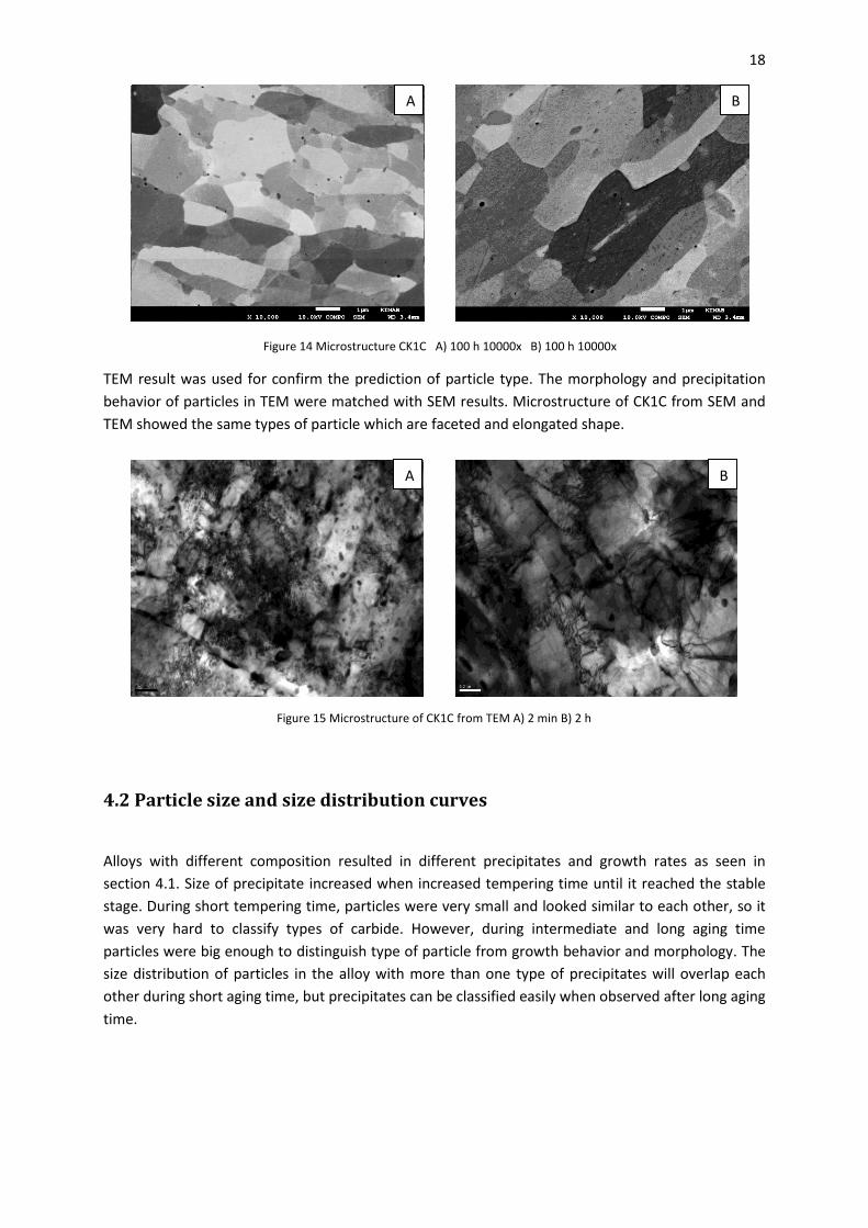
aging time, Fig.14, the matrix was no longer lath shaped. Instead, the matrix changed to an equiaxed
structure. The faceted particles were still the same size and located inside the grains. On the other
hand, the elongated particles had grown larger and were located at the grain boundaries. These
observations showed two types of carbides in this alloy.
C
D
B
C
A
F E
Figure 13 Microstructure CK1C A) 30 sec 10000x B) 2 min 10000x C) 30 min 10000x D) 30 min 30000x E) 2 h 10000x F) 2 h 30000x
18
TEM result was used for confirm the prediction of particle type. The morphology and precipitation
behavior of particles in TEM were matched with SEM results. Microstructure of CK1C from SEM and
TEM showed the same types of particle which are faceted and elongated shape.
4.2 Particle size and size distribution curves
Alloys with different composition resulted in different precipitates and growth rates as seen in
section 4.1. Size of precipitate increased when increased tempering time until it reached the stable
stage. During short tempering time, particles were very small and looked similar to each other, so it
was very hard to classify types of carbide. However, during intermediate and long aging time
particles were big enough to distinguish type of particle from growth behavior and morphology. The
size distribution of particles in the alloy with more than one type of precipitates will overlap each
other during short aging time, but precipitates can be classified easily when observed after long aging
time.
B A
Figure 14 Microstructure CK1C A) 100 h 10000x B) 100 h 10000x
B A
Figure 15 Microstructure of CK1C from TEM A) 2 min B) 2 h
19
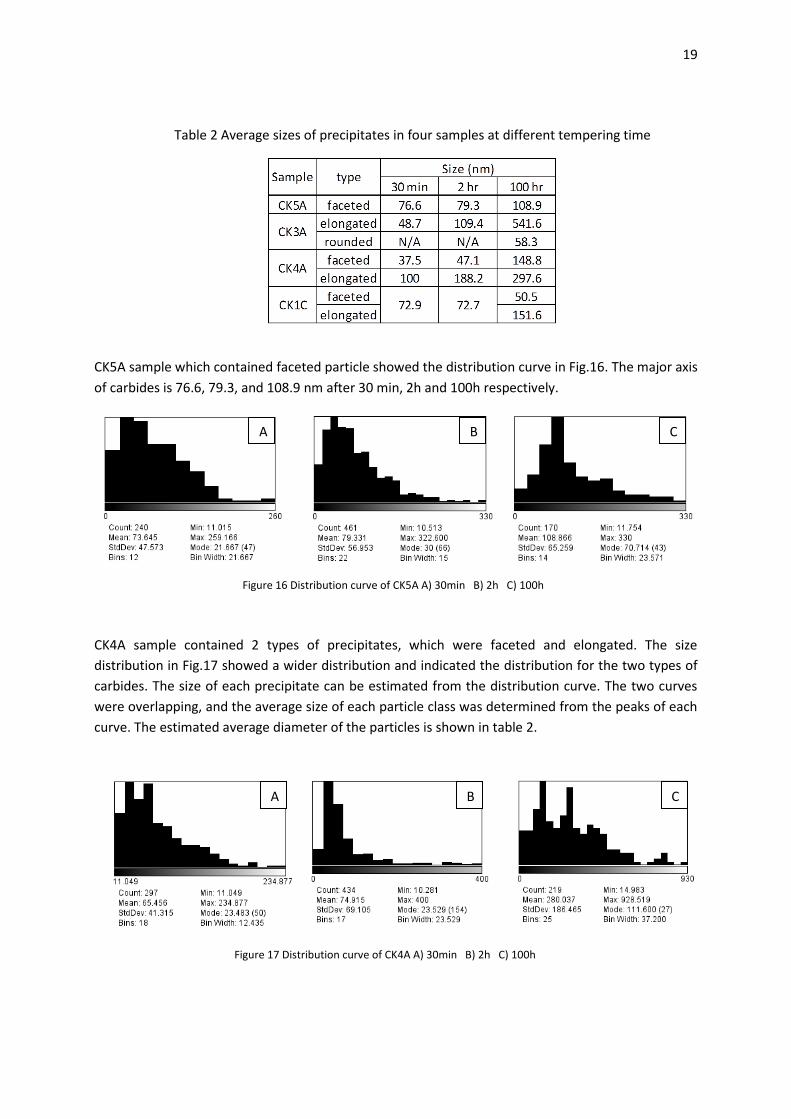
CK5A sample which contained faceted particle showed the distribution curve in Fig.16. The major axis
of carbides is 76.6, 79.3, and 108.9 nm after 30 min, 2h and 100h respectively.
CK4A sample contained 2 types of precipitates, which were faceted and elongated. The size
distribution in Fig.17 showed a wider distribution and indicated the distribution for the two types of
carbides. The size of each precipitate can be estimated from the distribution curve. The two curves
were overlapping, and the average size of each particle class was determined from the peaks of each
curve. The estimated average diameter of the particles is shown in table 2.
Table 2 Average sizes of precipitates in four samples at different tempering time
Figure 16 Distribution curve of CK5A A) 30min B) 2h C) 100h
A B C
Figure 17 Distribution curve of CK4A A) 30min B) 2h C) 100h
A B C
20
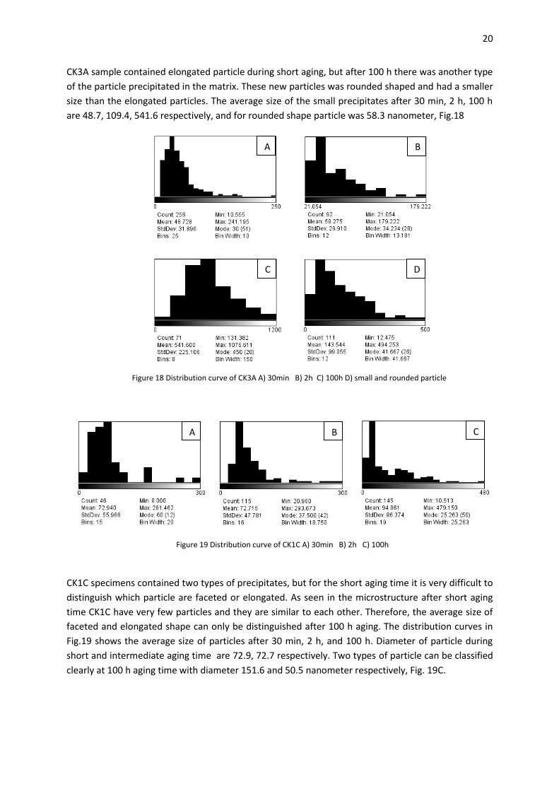
CK3A sample contained elongated particle during short aging, but after 100 h there was another type
of the particle precipitated in the matrix. These new particles was rounded shaped and had a smaller
size than the elongated particles. The average size of the small precipitates after 30 min, 2 h, 100 h
are 48.7, 109.4, 541.6 respectively, and for rounded shape particle was 58.3 nanometer, Fig.18
CK1C specimens contained two types of precipitates, but for the short aging time it is very difficult to
distinguish which particle are faceted or elongated. As seen in the microstructure after short aging
time CK1C have very few particles and they are similar to each other. Therefore, the average size of
faceted and elongated shape can only be distinguished after 100 h aging. The distribution curves in
Fig.19 shows the average size of particles after 30 min, 2 h, and 100 h. Diameter of particle during
short and intermediate aging time are 72.9, 72.7 respectively. Two types of particle can be classified
clearly at 100 h aging time with diameter 151.6 and 50.5 nanometer respectively, Fig. 19C.
Figure 19 Distribution curve of CK1C A) 30min B) 2h C) 100h
C B A
Figure 18 Distribution curve of CK3A A) 30min B) 2h C) 100h D) small and rounded particle
A B
C D
21
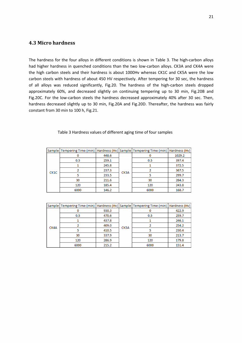
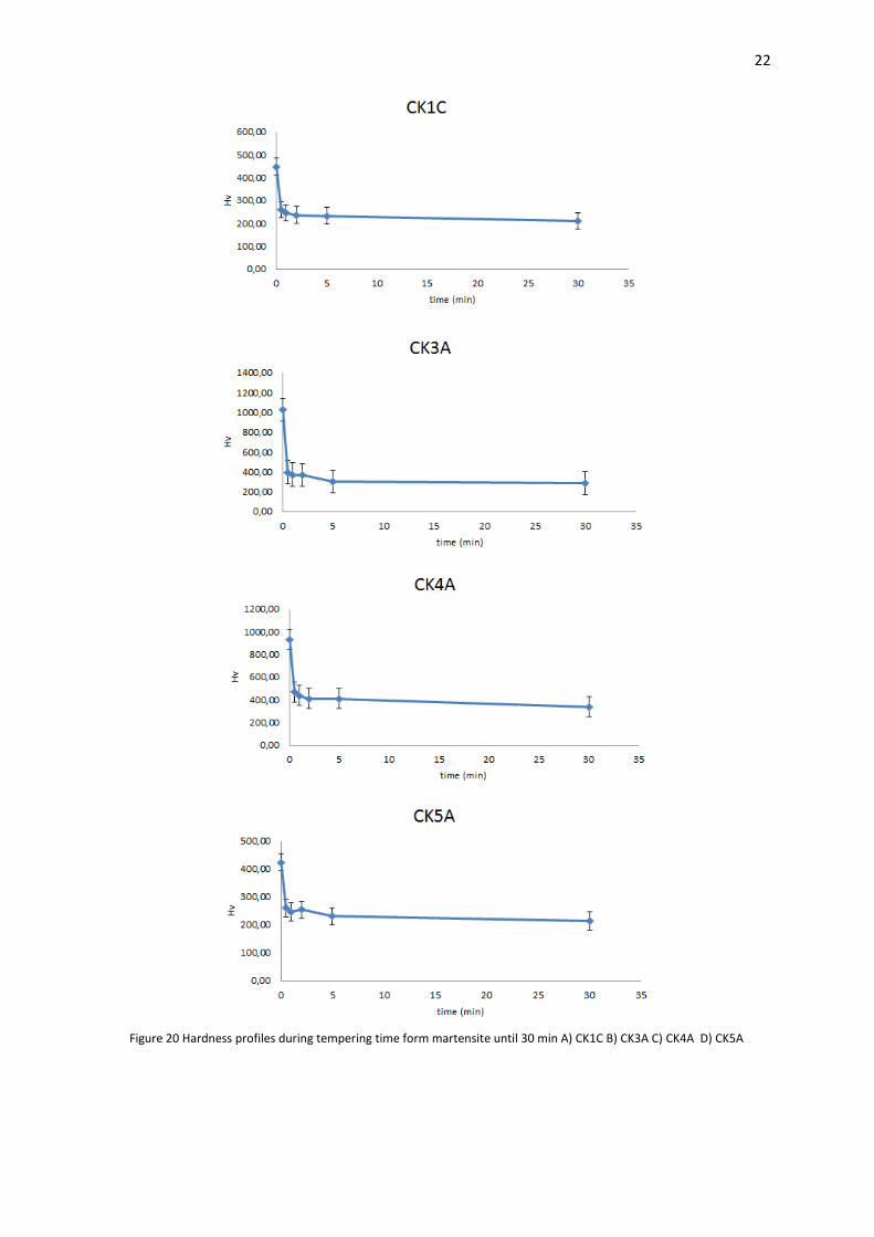
4.3 Micro hardness
The hardness for the four alloys in different conditions is shown in Table 3. The high-carbon alloys
had higher hardness in quenched conditions than the two low-carbon alloys. CK3A and CK4A were
the high carbon steels and their hardness is about 1000Hv whereas CK1C and CK5A were the low
carbon steels with hardness of about 450 HV respectively. After tempering for 30 sec, the hardness
of all alloys was reduced significantly, Fig.20. The hardness of the high-carbon steels dropped
approximately 60%, and decreased slightly on continuing tempering up to 30 min, Fig.20B and
Fig.20C. For the low-carbon steels the hardness decreased approximately 40% after 30 sec. Then,
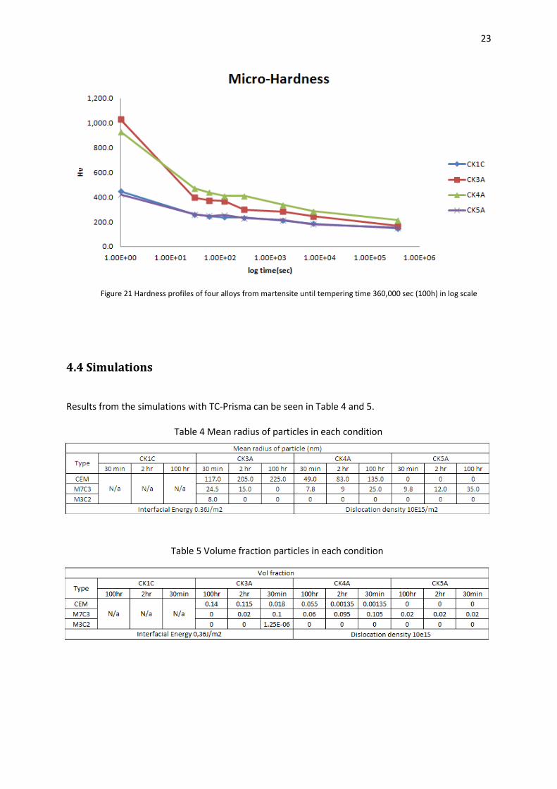
hardness decreased slightly up to 30 min, Fig.20A and Fig.20D. Thereafter, the hardness was fairly
constant from 30 min to 100 h, Fig.21.
Table 3 Hardness values of different aging time of four samples
22
Figure 20 Hardness profiles during tempering time form martensite until 30 min A) CK1C B) CK3A C) CK4A D) CK5A
23
4.4 Simulations
Results from the simulations with TC-Prisma can be seen in Table 4 and 5.
Table 5 Volume fraction particles in each condition
Table 4 Mean radius of particles in each condition
Figure 21 Hardness profiles of four alloys from martensite until tempering time 360,000 sec (100h) in log scale
24
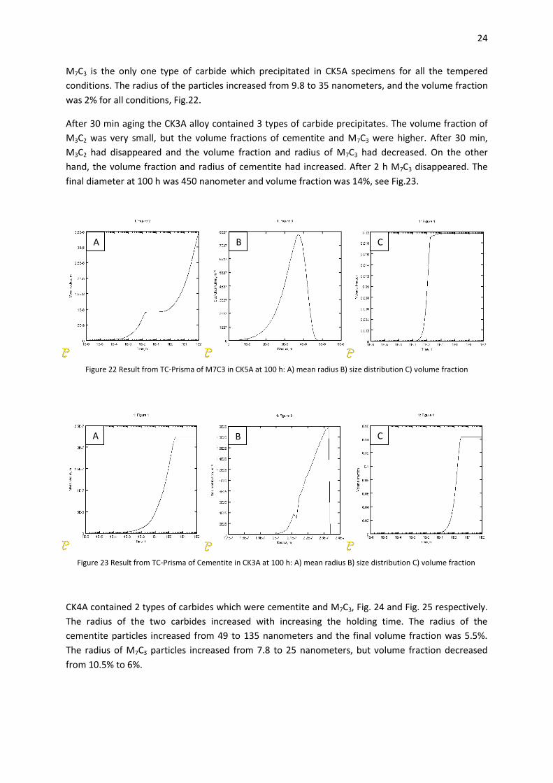
M7C3 is the only one type of carbide which precipitated in CK5A specimens for all the tempered
conditions. The radius of the particles increased from 9.8 to 35 nanometers, and the volume fraction
was 2% for all conditions, Fig.22.
After 30 min aging the CK3A alloy contained 3 types of carbide precipitates. The volume fraction of
M3C2 was very small, but the volume fractions of cementite and M7C3 were higher. After 30 min,
M3C2 had disappeared and the volume fraction and radius of M7C3 had decreased. On the other
hand, the volume fraction and radius of cementite had increased. After 2 h M7C3 disappeared. The
final diameter at 100 h was 450 nanometer and volume fraction was 14%, see Fig.23.
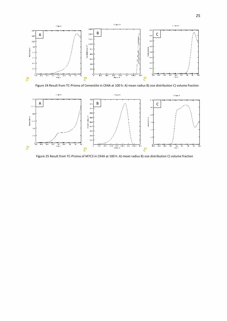
CK4A contained 2 types of carbides which were cementite and M7C3, Fig. 24 and Fig. 25 respectively.
The radius of the two carbides increased with increasing the holding time. The radius of the
cementite particles increased from 49 to 135 nanometers and the final volume fraction was 5.5%.
The radius of M7C3 particles increased from 7.8 to 25 nanometers, but volume fraction decreased
from 10.5% to 6%.
A B C
Figure 22 Result from TC-Prisma of M7C3 in CK5A at 100 h: A) mean radius B) size distribution C) volume fraction
A B C
Figure 23 Result from TC-Prisma of Cementite in CK3A at 100 h: A) mean radius B) size distribution C) volume fraction
25
A B C
Figure 24 Result from TC-Prisma of Cementite in CK4A at 100 h: A) mean radius B) size distribution C) volume fraction
A B C
Figure 25 Result from TC-Prisma of M7C3 in CK4A at 100 h: A) mean radius B) size distribution C) volume fraction
26
5. Discussion
5.1 Precipitates in Fe-Cr-C
Predictions from Thermo-Calc show that there is only one type of carbide in CK5A and CK3A samples.
Carbides in CK5A are M7C3 and in CK3A Cementite. On the other hand, CK4A and CK1C contain two
types of carbides which are M7C3 and Cementite. The results from the predictions were mostly
consistent with the results from TC-Prisma and experiments, but some samples gave different
results.
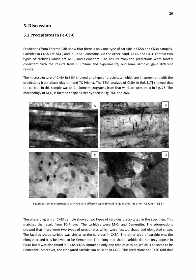
The microstructure of CK5A in SEM showed one type of precipitate, which are in agreement with the
predictions from phase diagram and TC-Prisma. The TEM analysis of CK5A in Ref. [17] showed that
the carbide in this sample was M7C3. Some micrographs from that work are presented in Fig. 26. The
morphology of M7C3 is faceted shape as clearly seen in Fig. 26C and 26D.
The phase diagram of CK4A sample showed two types of carbides precipitated in the specimen. This
matches the result from TC-Prisma. The carbides were M7C3 and Cementite. The observations
showed that there were two types of precipitates which were faceted shape and elongated shape.
The faceted shape carbide was similar to the carbides in CK5A. The other type of carbide was the
elongated and it is believed to be Cementite. The elongated shape carbide did not only appear in
CK4A but it was also found in CK3A. CK3A contained only one type of carbide, which is believed to be
Cementite. Moreover, the elongated carbide can be seen in CK1C. The predictions for CK1C told that
D C
A B
Figure 26 TEM microstructure of M7C3 with different aging time A) As-quenched B) 5 min C) 30min D) 6 h
27
this sample should contain Cementite and M7C3. The elongated carbide in CK4C is consistent with the
results from CK3A and CK1C. The observations of cementite carbide precipitation are supported by
the work in Ref. [23]. They studied the precipitation of cementite in Fe-1.08Cr-0.21C after tempering
by induction-heating for 40 sec or salt bath for 30 min at temperatures between 300-700oC.
Cementite precipitates were found to be needle shaped. When the tempering temperature was
increased the shape of cementite became more spherodized. In CK3A after 100 h aging there was
also another particle. The shape of this particle was rounded and it precipitates randomly. The
prediction from the phase diagram show only one type of carbide, but TC-Prisma showed metastable
carbides between 30 min and 2 h. The results from TC-Prisma showed that these metastable carbides
were M7C3 and M3C2. Since the shape of M7C3 has been found to be faceted it is believed that the
rounded particle is M3C2. After comparing all of the results from the four samples it can be concluded
that, the faceted shape particle is M7C3, the elongated particle is cementite, and the rounded is M3C2.
5.2 Comparison between experiments and simulations
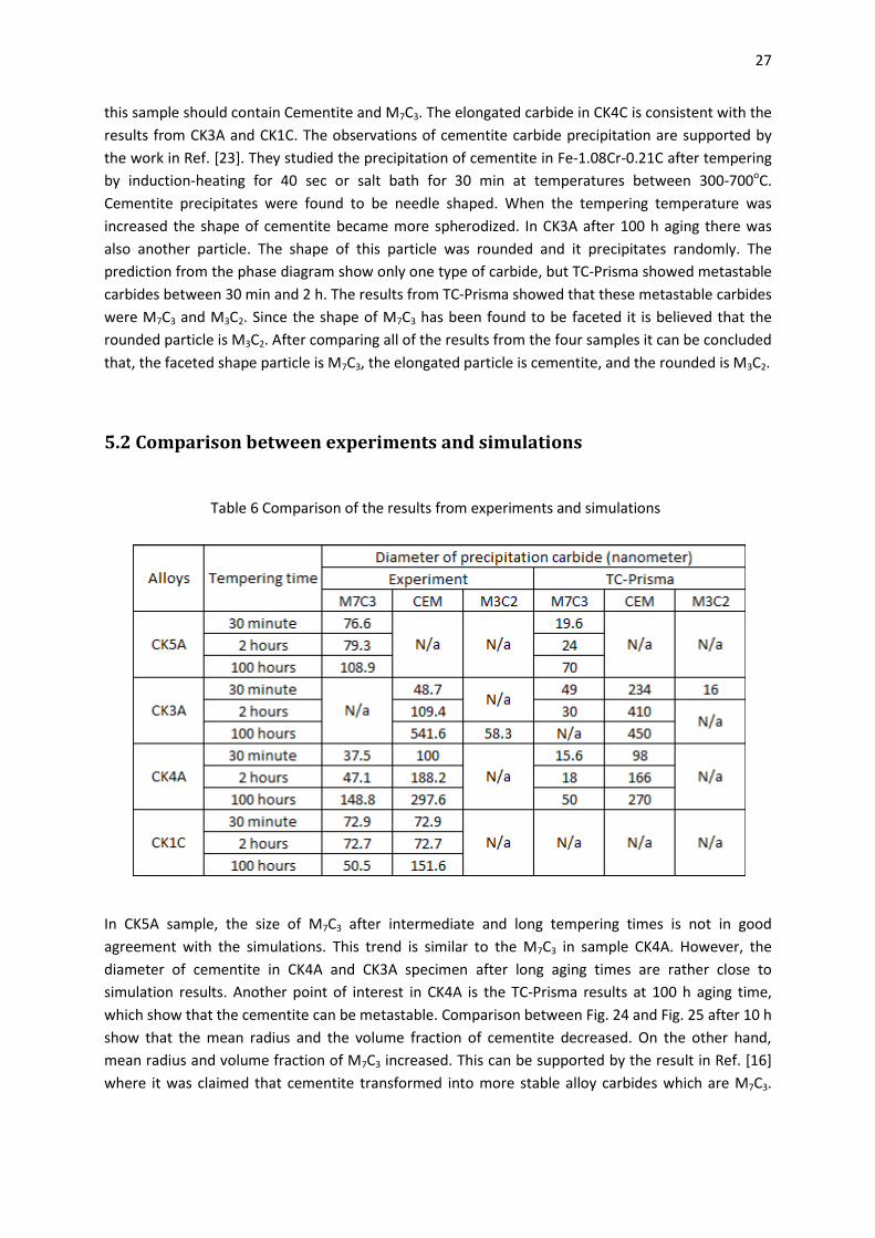
In CK5A sample, the size of M7C3 after intermediate and long tempering times is not in good
agreement with the simulations. This trend is similar to the M7C3 in sample CK4A. However, the
diameter of cementite in CK4A and CK3A specimen after long aging times are rather close to
simulation results. Another point of interest in CK4A is the TC-Prisma results at 100 h aging time,
which show that the cementite can be metastable. Comparison between Fig. 24 and Fig. 25 after 10 h
show that the mean radius and the volume fraction of cementite decreased. On the other hand,
mean radius and volume fraction of M7C3 increased. This can be supported by the result in Ref. [16]
where it was claimed that cementite transformed into more stable alloy carbides which are M7C3.
Table 6 Comparison of the results from experiments and simulations
28
Moreover, Michel et al. [26] showed that the metastable phase nucleates and grows faster than the
equilibrium phase.
TC-Prisma results from CK3A showed that the metastable phases M3C2 and M7C3 appear during
intermediate aging time and disappear after 1 and 5 h respectively.
After comparing the results between experiments and simulations it can be seen that the simulations
using TC-Prisma showed reasonable trends for precipitation of carbides. The comparison shows that
TC-Prisma can provide good results for precipitation in Fe-Cr-C system, but some parameters have to
be optimized. Interfacial energy and dislocation density are strongly affecting the diameter of the
carbides. Interfacial energy which is used in the current simulations are suitable for M7C3 in BCC
matrix, but the interfacial energy of Cementite and M3C2 in BCC matrix must be calculated to improve
the results.
5.3 Evolution of mechanical properties The results from hardness measurements in section 4.2 showed that the hardness dropped
significantly after 30 s of tempering. This phenomenon can occur in carbon steels due to recovery of
the martensite structure occurring during tempering at 700oC. This is consistent with the works in
Refs. [15, 23]. Speich et al. [15] studied the hardness of steel after tempering. The trend of
decreasing hardness is in agreement with this present work. The reason for the significant decrease
of hardness is that the tempering process can reduce the dislocation density in the martensitic
structure and rearrange some dislocations into sub-grains before recrystallization occur. When
recrystallization is finished all grains are equiaxed and strain free. However, low and medium carbon
steels cannot get fully recrystallize at 700oC, but it is enough to affect the hardness. After 30 sec, a lot
of carbides were precipitated and this mechanism would increase hardness by secondary hardening,
however, in the same time the matrix changed from martensite to ferrite. This change can decrease
the hardness more than effect of secondary hardening. Growth of ferrite together with the carbide
coarsening also affected the hardness. Secondary hardening can increase the hardness until a
particle reaches the critical radius, and above this size the efficiency of this mechanism decreases. In
alloy steels, alloy carbides can retard the hardness decrease more than in pure carbon steels, since
the hard alloy carbides force the dislocation to pass by Orowan looping mechanism instead of cutting
[24]. Since the stress needed to cut through hard carbide is higher than for soft particle, Orowan
looping will occur in tool steels at high stress levels instead of cutting. Another advantage of
chromium in hot work tool steel is that the size of carbides will increase slowly at high temperatures,
which means that hardness is retained.
29
6. Conclusions
There are three types of carbides, which are precipitating in the investigated Fe-Cr-C steels at
700oC. The three types of carbides are M7C3, Cementite and M3C2. The particle analysis showed that
M7C3 carbides are faceted, cementite is elongated and precipitate at grain boundaries as well as
intragranular, M3C2 are metastable with rounded shape and precipitate at long tempering time. The
trend of carbide growth from the experiments is consistent with TC-Prisma, but the size of the
carbides is quite different during initial and intermediate time aging. The parameters used in the
simulations such as dislocation density, mobility factors, and interfacial energy must be further
evaluated.
The hardness of the investigated steels will decrease fast during tempering. Factors which affect this
decrease are stress relief in matrix and structural transformation of the matrix from martensite to
ferrite. The mechanism that opposes the decreasing hardness is secondary hardening from the
precipitation hardening, but the effect of the change of matrix is more severe.
7. Future work
First suggestion would be to improve the data and knowledge about precipitation of carbides in each
condition. TEM thin foil analysis should be conducted for the important samples to get clear details
about the morphology of particles. Carbon Replica analysis including EDS analysis in TEM should be
used in order to prove the type of precipitates without obtaining signal from the matrix. For short
aging times, TEM analysis will give better understanding about the behavior and phenomena during
the nucleation of carbide precipitates. More statistics from particle measurements will generate
more reliable data and perhaps enable the separation of the distribution curve into 2 curves for the
samples that contain two types of carbides.
Heat treatments at other tempering conditions should be conducted for comparison. In addition, the
simulation results should be developed to better describe the results from experiments. In order to
improve the simulation results a parameter study in TC-Prisma is needed to get the suitable
parameter values for each type of carbide.

30
8. Acknowledgements
I would like to express my sincere gratitude to my supervisors, Peter Hedström and Joakim Odqvist,
for all their helpful guidance, encouragement and support throughout this work. I would also like to
express my gratitude to Prof. John Ågren for his willingness to serve as an examiner and for allowing
me to do this thesis with the Hero-m group at KTH.
I would like to thank my friends and colleagues, Mercy, Wallop, Zhalah, Sara, and all of Thai friends
for their help, encouragement, friendships and made all those years pleasant and enjoyable. Thanks
to my best friend, Chaiyapat Tangpatjaroen for his support.
Finally I would like to express my deepest gratitude to the most wonderful persons in my life, my
parents, for their support and encouragement during my study in Sweden.
Chanachon Techaboonanek
Stockholm, September 2012
31
9. References
[1] A. Inoue and T. Masumoto, 1980, “Carbide Reactions (M3C-> M7C3-> M23C6 -> M6C) During
Tempering of Rapidly Solidified High Carbon Cr-W and Cr-Mo Steels”, Metallurgical
Transactions A, vol. 11A, pp. 739-747.
[2] L.R. Woodyatt and G. Krauss, 1976, “Iron-Chromium-Carbon System at 870oC”, Metallurgical
Transactions A, vol.7A, pp. 983-990.
[3] M. Umemoto, E. Yoshitake and I. Tamura, 1983, “The Morphology of Matensite in Fe-C, Fe-Ni-
C, Fe-Cr-C Alloys”, Journal of Materials Science, vol. 18, pp. 2893-2904.
[4] W.C. Leslie, 1981, “The Physical Metallurgy of Steels”, McGraw-Hill.
[5] G. Roberts, G. Krauss and R. Kennedy, 1998, “Tool Steels”, ASM International
[6] Thermo-Calc software AB, 2011, TC-Prisma User’s guide and examples version 1.0,
<http://www.thermocalc.com/res/Manuals/TC-PRISMA-Users-Guide-and-Examples-2.pdf>.
[7] S. Manus, 2000, “Steel”, The Engineering Institute of Thailand under H.M. the King’s Patronage.
[8] H. Yuehui, R. Quihua and T. Yuhua, 1996, “Investigation on The Morphology of Martensite in
Carbon Steels”, Journal of Central South University, vol.3, No.2, pp. 122-135.
[9] H.K.D.H. Bhadeshia and R. Honeycombe, 2006, “Steels Microstructure and Properties”, Elsevier
Ltd.
[10] M.F. Carlson, B.V.N. Rao, G. Thomas, 1979, “The Effect of Austenitizing Temperature upon The
Microstructure and Mechanical Properties of Experimental Fe/Cr/C Steels”, Metallurgical
Transactions A, vol. 10A, pp. 1273-1284.
[11] Z.K. Liu and J. Ågren, 1991, “Morphology of Cementite Decomposition in Fe-Cr-C Alloy”,
Metallurgical Transactions A, vol.22A, pp. 1753-1759.
[12] F.R. Palmer and G.V. Luerssen, 1960, “Tool Steel Simplified”, The Carpenter Steel Company.
[13] A.V. Sverdlin and A.R. Ness, 1997, “Fundamental Concepts in Steel Heat Treatment”, in G.E.
Totten and M.A.H. Howes (eds), “Steel Heat Treatment Handbook”, 2nd edition Marcel Dekker
INC.
[14] R.E. Haimbaugh, 2001, “Practical Induction Heat Treatment”, ASM International.
[15] G.R. Speich and W.C. Leslie, 1972, “Tempering of Steel”, Metallurgical Transactions, vol.3, pp.
1043-1054.
[16] G.R. Speich and K.A. Taylor, 1992, “Tempering of Ferrous Martensites”, in G.B. Olson and W.S.
Owen (eds), Martensite a Tribute to Morris Cohen, ASM International.
[17] P. Hedström, J. Odqvist, Q. Chen, 2010, unpublished work.
[18] K.H. Prabhudev, 1988, “Handbook of Heat Treatment of Steels”, Twelfth reprint 2008, Tata
McGraw-Hill.
[19] A. Mazzoli and O. Favoni, 2012, “Particle Size, Size Distribution and Morphological Evaluation of
Airborne Dust Particles of Diverse Woods by Scanning Electron Microscopy and Image
Processing Program”, Powder Technology, Article in press.
[20] C. Igathinathane, L.O. Pordesimo, E.P. Columbus, W.D. Batchelor and S.R. Methuku, 2008,
“Shape Identification and Particles Size Distribution from Basic Shape Parameter using ImageJ”,
Computer and Electronics in Agriculture, vol. 63, pp. 168-182.
[21] T. Ferreira and W. Rasband, 2011, “ImageJ user guide”, v1.45, < http://rsbweb.nih.gov/ij/docs/
guide/index.html>.

32
[22] The American Society for Testing and Materials (ASTM), Standard Test Method for
Microindentation Hardness of Materials, E384 – 99.
[23] S.T. Ahn, D.S. Kim and W.J. Nam, 2005, “Microstructural Evolution and Mechanical Properties
of Low Alloy Steel Tempered by Induction Heating”, Journal of Materials Processing
Technology, vol. 160, pp. 54-58.
[24] J. Andersson, 2011, “Secondary Hardening in some Low-Chromium Hotwork Tool Steels”,
Thesis for the Degree of Doctor of Philosophy, Chalmers University of Technology,
Chalmersbibliotekets reproservice.