Embed Size (px)
Citation preview
ScanExpress™ IEEE-1149.x Structural/Functional Test and
In-System Programming Solutions
64-bit Windows XP, Vista, 7, & 8 OS support with an easy-to-
use Graphical User Interface
Automatically generates test patterns for Infrastructure, Interconnect, Memories, FIFOs, Clusters, and Resistors using proven, mature
boundary-scan test algorithms
Summary and comprehensive
reports of board test coverage
Fault detection and isolation to the net and pin-level including bridges for interconnects and
memories
Graphical Fault Viewer identifies the physical
locations of the faults
High-performance In-System Programming (ISP) of Flash memories, Serial EEPROMs, CPLDs, FPGAs, and other
programmable devices
True parallel testing (gang)
and in-system programming
Built-in test sequencer for automatic execution of independent tests with user
specified order and conditions
High-level debugger featuring waveform representation of applied, expected, and actual test data including go from, breakpoints, looping, and
single-step
Support for LabVIEW, LabWindows/CVI, Agilent VEE, NI TestStand, and other third
party test executives
Integration with industry standard In-Circuit Testers,
MDAs, and Flying Probers
High-performance boundary-scan controllers including direct programming support
for I2C and SPI devices
Support for hierarchical
devices and system level test
Introduction
Since its inception in the mid- eighties and its adoption by the IEEE organization as an international standard, boundary-scan technology has rapidly become the technology of choice for building reliable, high-technology, electronic products with a high degree of testability.
As a firm believer in supporting global standards, Corelis has played a pioneering role in bringing affordable IEEE-1149.x compliant tools and products to market in a timely fashion. This has allowed a growing number of customers to incorporate boundary-scan technology into their products in order to gain a competitive edge in today's marketplace.
The knowledge and experience gained by Corelis in many years of active participation in the boundary-scan market has enabled us to offer an unparalleled array of boundary-scan tools, training, and consulting services to customers worldwide.
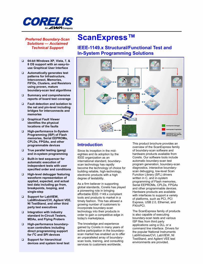
This product brochure provides an overview of the ScanExpress family of boundary-scan software and hardware products available from Corelis. Our software tools include automatic boundary-scan test program generation, boundary-scan diagnostics, interactive boundary-scan debugging, low-level Scan Function Library (SFL) drivers written in C, and in-system programming of Flash memories, Serial EEPROMs, CPLDs, FPGAs and other programmable devices. Hardware products are available with interfaces to support a variety of platforms, such as PCI, PCI Express, USB 2.0, Ethernet, and PXI/cPCI.
The ScanExpress family of products is also capable of executing boundary-scan tests and various ISP files from third party applications using a DLL or a command line interface. Drivers for the popular National Instruments LabWindows/CVI, LabVIEW, NI TestStand, and Agilent VEE test environments are provided.
Preferred Boundary-Scan Solutions — Acclaimed
Technical Support
Corelis Products and
Services
Test and Programming Software
Corelis’ ScanExpress software offers a fully integrated development environment that includes structural and functional test program generation, test execution, in-system programming, and productivity enhancing utilities.
Boundary-Scan Controllers
Controllers are compatible with buses, such as PCI, PCI Express, PXI/cPCI, USB 2.0, and Ethernet. Controllers are available with support up to a 100MHz sustained TCK frequency.
Boundary-Scan I/O Modules
The ScanIO™ family of I/O modules add control and visibility to connectors, traces, and logic that otherwise are not accessible using traditional JTAG techniques.
High-Volume Production Systems
Corelis offers gang boundary-scan test and in-system programming systems enabling concurrent testing and in-system programming of CPLD and Flash devices. A wide variety of deployment options are available using a single PC and a single operator for multi-board test.
Test Executive Support
Third party applications can execute Corelis software tools using a DLL or a command line interface.
Integration with ICTs, MDAs, and
Flying Probers
The ability to reuse vectors saves time and reduces cost. Corelis offers integration paths with other test technologies, such as In-Circuit Testers, Manufacturing Defect Analyzers, and Flying Probers.
Engineering Services
Corelis offers various engineering services, such as design-for-testability analysis, test procedure development, and test fixture integration.
Training Classes and Seminars
Corelis offers in-depth training classes that include boundary-scan tutorials and hands-on labs. We also host free seminars worldwide to keep industries informed about the latest developments in the JTAG/boundary-scan test and in-system programming fields.
Product Life-Cycle
Support
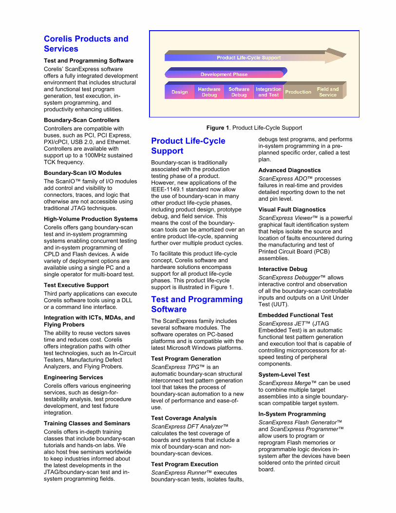
Boundary-scan is traditionally associated with the production testing phase of a product. However, new applications of the IEEE-1149.1 standard now allow the use of boundary-scan in many other product life-cycle phases, including product design, prototype debug, and field service. This means the cost of the boundary-scan tools can be amortized over an entire product life-cycle, spanning further over multiple product cycles.
To facilitate this product life-cycle concept, Corelis software and hardware solutions encompass support for all product life-cycle phases. This product life-cycle support is illustrated in Figure 1.
Test and Programming
Software
The ScanExpress family includes several software modules. The software operates on PC-based platforms and is compatible with the latest Microsoft Windows platforms.
Test Program Generation
ScanExpress TPG™ is an automatic boundary-scan structural interconnect test pattern generation tool that takes the process of boundary-scan automation to a new level of performance and ease-of-use.
Test Coverage Analysis
ScanExpress DFT Analyzer™ calculates the test coverage of boards and systems that include a mix of boundary-scan and non-boundary-scan devices.
Test Program Execution
ScanExpress Runner™ executes boundary-scan tests, isolates faults,
debugs test programs, and performs in-system programming in a pre-planned specific order, called a test plan.
Advanced Diagnostics
ScanExpress ADO™ processes failures in real-time and provides detailed reporting down to the net and pin level.
Visual Fault Diagnostics
ScanExpress Viewer™ is a powerful graphical fault identification system that helps isolate the source and location of faults encountered during the manufacturing and test of Printed Circuit Board (PCB) assemblies.
Interactive Debug
ScanExpress Debugger™ allows interactive control and observation of all the boundary-scan controllable inputs and outputs on a Unit Under Test (UUT).
Embedded Functional Test
ScanExpress JET™ (JTAG Embedded Test) is an automatic functional test pattern generation and execution tool that is capable of controlling microprocessors for at-speed testing of peripheral components.
System-Level Test
ScanExpress Merge™ can be used to combine multiple target assemblies into a single boundary-scan compatible target system.
In-System Programming
ScanExpress Flash Generator™ and ScanExpress Programmer™ allow users to program or reprogram Flash memories or programmable logic devices in-system after the devices have been soldered onto the printed circuit board.
Figure 1. Product Life-Cycle Support
Test Program Generation
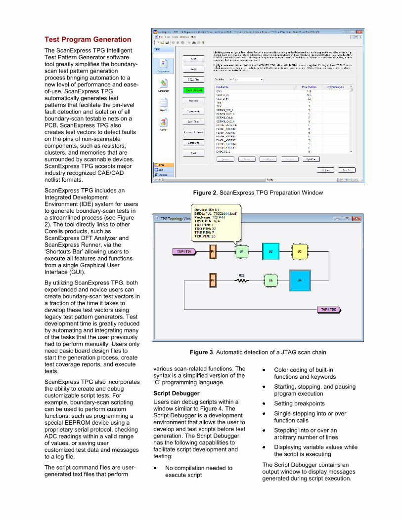
The ScanExpress TPG Intelligent Test Pattern Generator software tool greatly simplifies the boundary-scan test pattern generation process bringing automation to a new level of performance and ease-of-use. ScanExpress TPG automatically generates test patterns that facilitate the pin-level fault detection and isolation of all boundary-scan testable nets on a PCB. ScanExpress TPG also creates test vectors to detect faults on the pins of non-scannable components, such as resistors, clusters, and memories that are surrounded by scannable devices. ScanExpress TPG accepts major industry recognized CAE/CAD netlist formats.
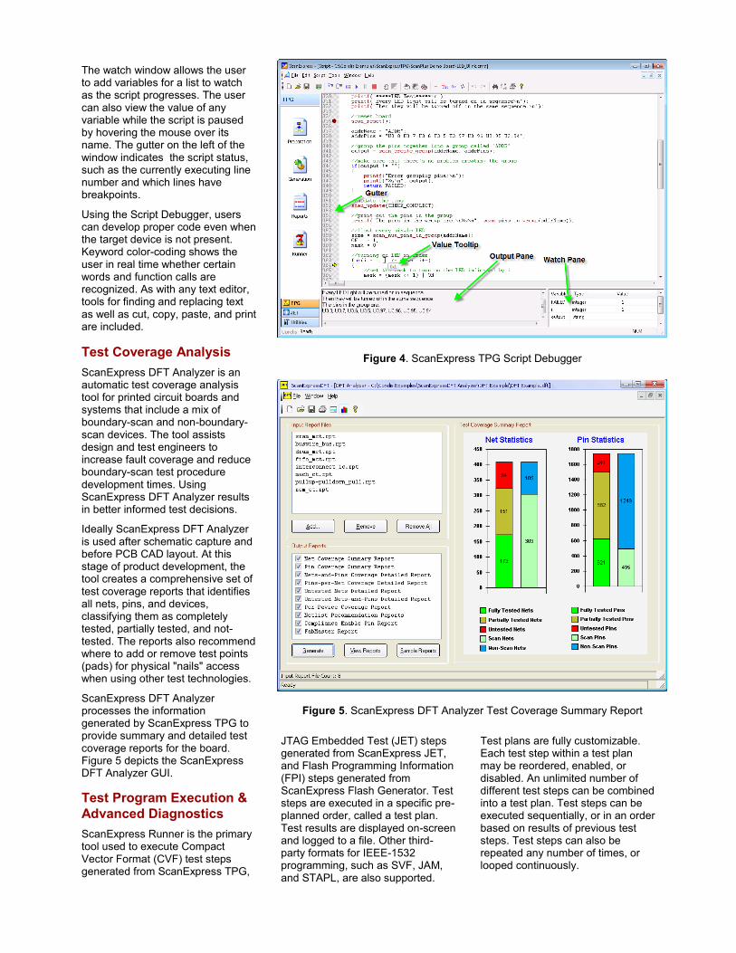
ScanExpress TPG includes an Integrated Development Environment (IDE) system for users to generate boundary-scan tests in a streamlined process (see Figure 2). The tool directly links to other Corelis products, such as ScanExpress DFT Analyzer and ScanExpress Runner, via the ‘Shortcuts Bar’ allowing users to execute all features and functions from a single Graphical User Interface (GUI).
By utilizing ScanExpress TPG, both experienced and novice users can create boundary-scan test vectors in a fraction of the time it takes to develop these test vectors using legacy test pattern generators. Test development time is greatly reduced by automating and integrating many of the tasks that the user previously had to perform manually. Users only need basic board design files to start the generation process, create test coverage reports, and execute tests.
ScanExpress TPG also incorporates the ability to create and debug customizable script tests. For example, boundary-scan scripting can be used to perform custom functions, such as programming a special EEPROM device using a proprietary serial protocol, checking ADC readings within a valid range of values, or saving user customized test data and messages to a log file.
The script command files are user- generated text files that perform
various scan-related functions. The syntax is a simplified version of the ‘C’ programming language.
Script Debugger
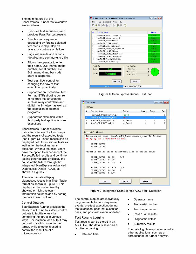
Users can debug scripts within a window similar to Figure 4. The Script Debugger is a development environment that allows the user to develop and test scripts before test generation. The Script Debugger has the following capabilities to facilitate script development and testing:
No compilation needed to
execute script
Color coding of built-in
functions and keywords
Starting, stopping, and pausing
program execution
Setting breakpoints
Single-stepping into or over
function calls
Stepping into or over an
arbitrary number of lines
Displaying variable values while
the script is executing
The Script Debugger contains an output window to display messages generated during script execution.
Figure 3. Automatic detection of a JTAG scan chain
Figure 2. ScanExpress TPG Preparation Window
The watch window allows the user to add variables for a list to watch as the script progresses. The user can also view the value of any variable while the script is paused by hovering the mouse over its name. The gutter on the left of the window indicates the script status, such as the currently executing line number and which lines have breakpoints.
Using the Script Debugger, users can develop proper code even when the target device is not present. Keyword color-coding shows the user in real time whether certain words and function calls are recognized. As with any text editor, tools for finding and replacing text as well as cut, copy, paste, and print are included.
Test Coverage Analysis
ScanExpress DFT Analyzer is an automatic test coverage analysis tool for printed circuit boards and systems that include a mix of boundary-scan and non-boundary-scan devices. The tool assists design and test engineers to increase fault coverage and reduce boundary-scan test procedure development times. Using ScanExpress DFT Analyzer results in better informed test decisions.
Ideally ScanExpress DFT Analyzer is used after schematic capture and before PCB CAD layout. At this stage of product development, the tool creates a comprehensive set of test coverage reports that identifies all nets, pins, and devices, classifying them as completely tested, partially tested, and not-tested. The reports also recommend where to add or remove test points (pads) for physical "nails" access when using other test technologies.
ScanExpress DFT Analyzer processes the information generated by ScanExpress TPG to provide summary and detailed test coverage reports for the board. Figure 5 depicts the ScanExpress DFT Analyzer GUI.
Test Program Execution &
Advanced Diagnostics
ScanExpress Runner is the primary tool used to execute Compact Vector Format (CVF) test steps generated from ScanExpress TPG,
Figure 4. ScanExpress TPG Script Debugger
Figure 5. ScanExpress DFT Analyzer Test Coverage Summary Report
JTAG Embedded Test (JET) steps generated from ScanExpress JET, and Flash Programming Information (FPI) steps generated from ScanExpress Flash Generator. Test steps are executed in a specific pre-planned order, called a test plan. Test results are displayed on-screen and logged to a file. Other third-party formats for IEEE-1532 programming, such as SVF, JAM, and STAPL, are also supported.
Test plans are fully customizable. Each test step within a test plan may be reordered, enabled, or disabled. An unlimited number of different test steps can be combined into a test plan. Test steps can be executed sequentially, or in an order based on results of previous test steps. Test steps can also be repeated any number of times, or looped continuously.
The main features of the ScanExpress Runner test executive are as follows:
Executes test sequences and
provides Pass/Fail test results
Enables test sequence
debugging by forcing selected test steps to skip, stop on failure, or continue on failure
Logs test results and reports
(detailed and summary) to a file
Allows the operator to enter
their name, UUT name, model number, serial number, etc. Both manual and bar code entry is supported.
Test plan flow control for
changing the flow of test execution dynamically
Support for an Extensible Test
Format (ETF) allowing control of external test equipment, such as relay controllers and digital multi-meters, as well as the execution of external programs
Support for execution within
third party test applications and executives
ScanExpress Runner provides users an overview of all test steps and the results of executed tests (see Figure 6). These results can be displayed both for individual tests as well as for the total test runs executed. When a test fails, users have the option to either accept the Passed/Failed results and continue testing other boards or display the cause of the failure through the integrated ScanExpress Advanced Diagnostics Option (ADO), as shown in Figure 7.
The user can also display diagnostics results in a Truth-Table format as shown in Figure 8. This display can be customized by showing or hiding relevant information columns and by sorting the data in each column.
Control Outputs
ScanExpress Runner provides the ability to utilize up to sixteen control outputs to facilitate tests by controlling the target in various ways. For instance, one output may be used to switch power to the target, while another is used to control the reset line of a microprocessor.
The control outputs are individually programmable for four sequential events: pre-test execution, during test execution, post-test execution-pass, and post-test execution-failed.
Test Results Logging
Test results can be stored in an ASCII file. The data is saved as a text file containing:
Date and time
Operator name
Test serial number
Test steps names
Pass / Fail results
Diagnostic details
Summary results
The data log file may be imported to other applications, such as a spreadsheet for further analysis.
Figure 7. Integrated ScanExpress ADO Fault Detection
Figure 6. ScanExpress Runner Test Plan
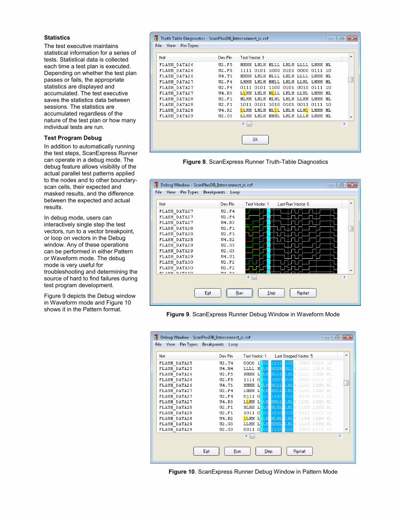
Statistics
The test executive maintains statistical information for a series of tests. Statistical data is collected each time a test plan is executed. Depending on whether the test plan passes or fails, the appropriate statistics are displayed and accumulated. The test executive saves the statistics data between sessions. The statistics are accumulated regardless of the nature of the test plan or how many individual tests are run.
Test Program Debug
In addition to automatically running the test steps, ScanExpress Runner can operate in a debug mode. The debug feature allows visibility of the actual parallel test patterns applied to the nodes and to other boundary-scan cells, their expected and masked results, and the difference between the expected and actual results.
In debug mode, users can interactively single step the test vectors, run to a vector breakpoint, or loop on vectors in the Debug window. Any of these operations can be performed in either Pattern or Waveform mode. The debug mode is very useful for troubleshooting and determining the source of hard to find failures during test program development.
Figure 9 depicts the Debug window in Waveform mode and Figure 10 shows it in the Pattern format.
Figure 9. ScanExpress Runner Debug Window in Waveform Mode
Figure 10. ScanExpress Runner Debug Window in Pattern Mode
Figure 8. ScanExpress Runner Truth-Table Diagnostics
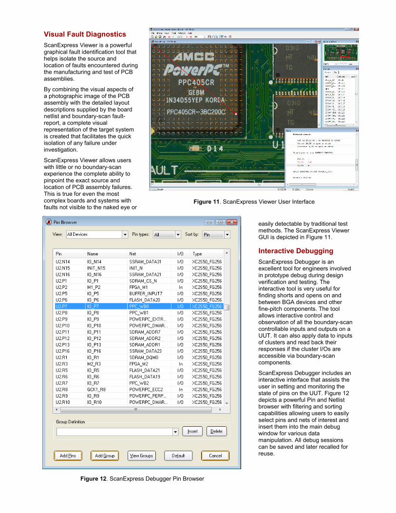
Visual Fault Diagnostics
ScanExpress Viewer is a powerful graphical fault identification tool that helps isolate the source and location of faults encountered during the manufacturing and test of PCB assemblies.
By combining the visual aspects of a photographic image of the PCB assembly with the detailed layout descriptions supplied by the board netlist and boundary-scan fault-report, a complete visual representation of the target system is created that facilitates the quick isolation of any failure under investigation.
ScanExpress Viewer allows users with little or no boundary-scan experience the complete ability to pinpoint the exact source and location of PCB assembly failures. This is true for even the most complex boards and systems with faults not visible to the naked eye or
Figure 12. ScanExpress Debugger Pin Browser
Figure 11. ScanExpress Viewer User Interface
easily detectable by traditional test methods. The ScanExpress Viewer GUI is depicted in Figure 11.
Interactive Debugging
ScanExpress Debugger is an excellent tool for engineers involved in prototype debug during design verification and testing. The interactive tool is very useful for finding shorts and opens on and between BGA devices and other fine-pitch components. The tool allows interactive control and observation of all the boundary-scan controllable inputs and outputs on a UUT. It can also apply data to inputs of clusters and read back their responses if the cluster I/Os are accessible via boundary-scan components.
ScanExpress Debugger includes an interactive interface that assists the user in setting and monitoring the state of pins on the UUT. Figure 12 depicts a powerful Pin and Netlist browser with filtering and sorting capabilities allowing users to easily select pins and nets of interest and insert them into the main debug window for various data manipulation. All debug sessions can be saved and later recalled for reuse.
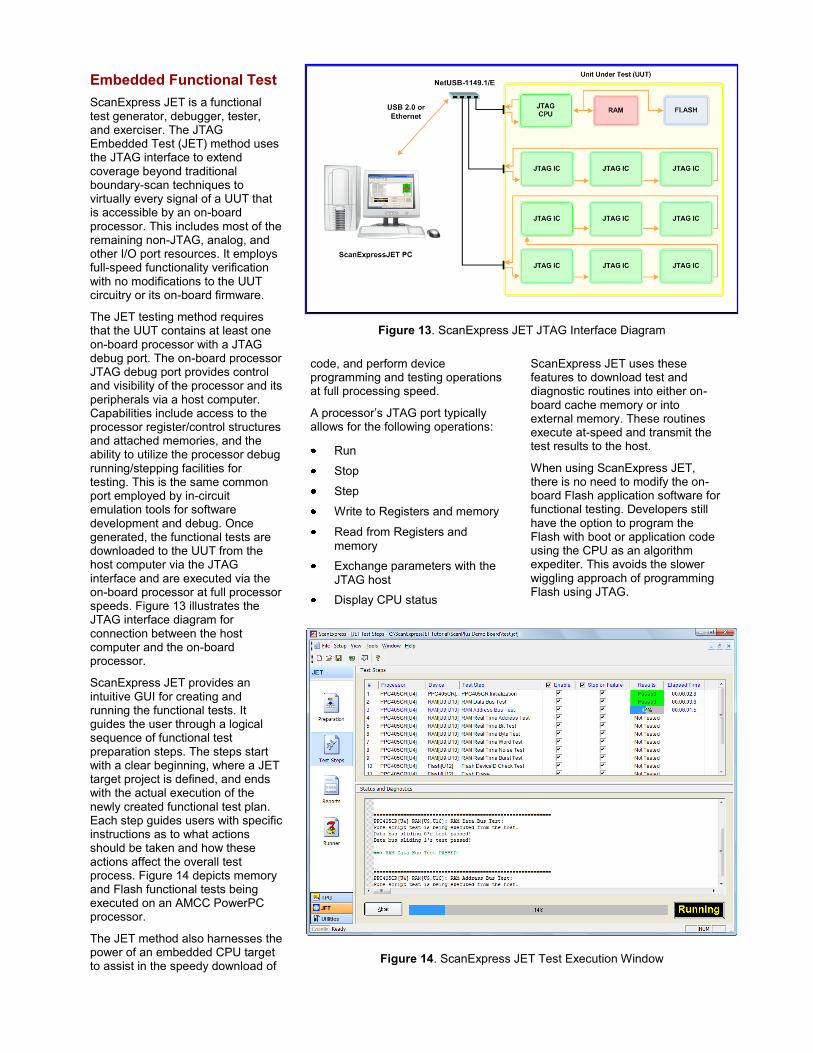
Embedded Functional Test
ScanExpress JET is a functional test generator, debugger, tester, and exerciser. The JTAG Embedded Test (JET) method uses the JTAG interface to extend coverage beyond traditional boundary-scan techniques to virtually every signal of a UUT that is accessible by an on-board processor. This includes most of the remaining non-JTAG, analog, and other I/O port resources. It employs full-speed functionality verification with no modifications to the UUT circuitry or its on-board firmware.
The JET testing method requires that the UUT contains at least one on-board processor with a JTAG debug port. The on-board processor JTAG debug port provides control and visibility of the processor and its peripherals via a host computer. Capabilities include access to the processor register/control structures and attached memories, and the ability to utilize the processor debug running/stepping facilities for testing. This is the same common port employed by in-circuit emulation tools for software development and debug. Once generated, the functional tests are downloaded to the UUT from the host computer via the JTAG interface and are executed via the on-board processor at full processor speeds. Figure 13 illustrates the JTAG interface diagram for connection between the host computer and the on-board processor.
ScanExpress JET provides an intuitive GUI for creating and running the functional tests. It guides the user through a logical sequence of functional test preparation steps. The steps start with a clear beginning, where a JET target project is defined, and ends with the actual execution of the newly created functional test plan. Each step guides users with specific instructions as to what actions should be taken and how these actions affect the overall test process. Figure 14 depicts memory and Flash functional tests being executed on an AMCC PowerPC processor.
The JET method also harnesses the power of an embedded CPU target to assist in the speedy download of
Figure 14. ScanExpress JET Test Execution Window
Figure 13. ScanExpress JET JTAG Interface Diagram
code, and perform device programming and testing operations at full processing speed.
A processor’s JTAG port typically allows for the following operations:
Run
Stop
Step
Write to Registers and memory
Read from Registers and
memory
Exchange parameters with the
JTAG host
Display CPU status
ScanExpress JET uses these features to download test and diagnostic routines into either on-board cache memory or into external memory. These routines execute at-speed and transmit the test results to the host.
When using ScanExpress JET, there is no need to modify the on-board Flash application software for functional testing. Developers still have the option to program the Flash with boot or application code using the CPU as an algorithm expediter. This avoids the slower wiggling approach of programming Flash using JTAG.
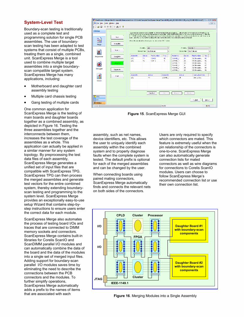
System-Level Test
Boundary-scan testing is traditionally used as a complete test and programming solution for single PCB assemblies. The use of boundary-scan testing has been adapted to test systems that consist of multiple PCBs, treating them as a single, combined unit. ScanExpress Merge is a tool used to combine multiple target assemblies into a single boundary-scan compatible target system. ScanExpress Merge has many applications, including:
Motherboard and daughter card
assembly testing
Multiple card chassis testing
Gang testing of multiple cards
One common application for ScanExpress Merge is the testing of main boards and daughter boards together as a combined assembly, as depicted in Figure 16. Testing the three assemblies together and the interconnects between them, increases the test coverage of the assemblies as a whole. This application can actually be applied in a similar manner for any system topology. By preprocessing the test data files of each assembly, ScanExpress Merge generates a unified set of input files that are compatible with ScanExpress TPG. ScanExpress TPG can then process the merged assemblies and generate test vectors for the entire combined system, thereby extending boundary-scan testing and programming to the system level. ScanExpress Merge provides an exceptionally easy-to-use setup Wizard that contains step-by-step instructions to ensure users enter the correct data for each module.
ScanExpress Merge also automates the process of testing board I/Os and traces that are connected to DIMM memory sockets and connectors. ScanExpress Merge contains built-in libraries for Corelis ScanIO and ScanDIMM parallel I/O modules and can automatically combine the data of the board and the data of the modules into a single set of merged input files. Adding support for boundary-scan parallel I/O modules saves time by eliminating the need to describe the connections between the PCB connectors and the modules. To further simplify operations, ScanExpress Merge automatically adds a prefix to the names of items that are associated with each
assembly, such as net names, device identifiers, etc. This allows the user to uniquely identify each assembly within the combined system and to properly diagnose faults when the complete system is tested. The default prefix is optional for each of the merged assemblies and can be changed by the user.
When connecting boards using paired mating connectors, ScanExpress Merge automatically finds and connects the relevant nets on both sides of the connectors.
Users are only required to specify which connectors are mated. This feature is extremely useful when the pin relationship of the connectors is one-to-one. ScanExpress Merge can also automatically generate connection lists for mated connectors as well as wire diagrams for connections to Corelis ScanIO modules. Users can choose to follow ScanExpress Merge’s recommended connection list or use their own connection list.
Figure 16. Merging Modules into a Single Assembly
Cluster
I/O
I/O
JTAG
IEEE-1149.1
ProcessorCPLD
FPGA
Daughter Board #2
with boundary-scan
components
Daughter Board #1
with boundary-scan
components
Cluster
Figure 15. ScanExpress Merge GUI
In-System Programming
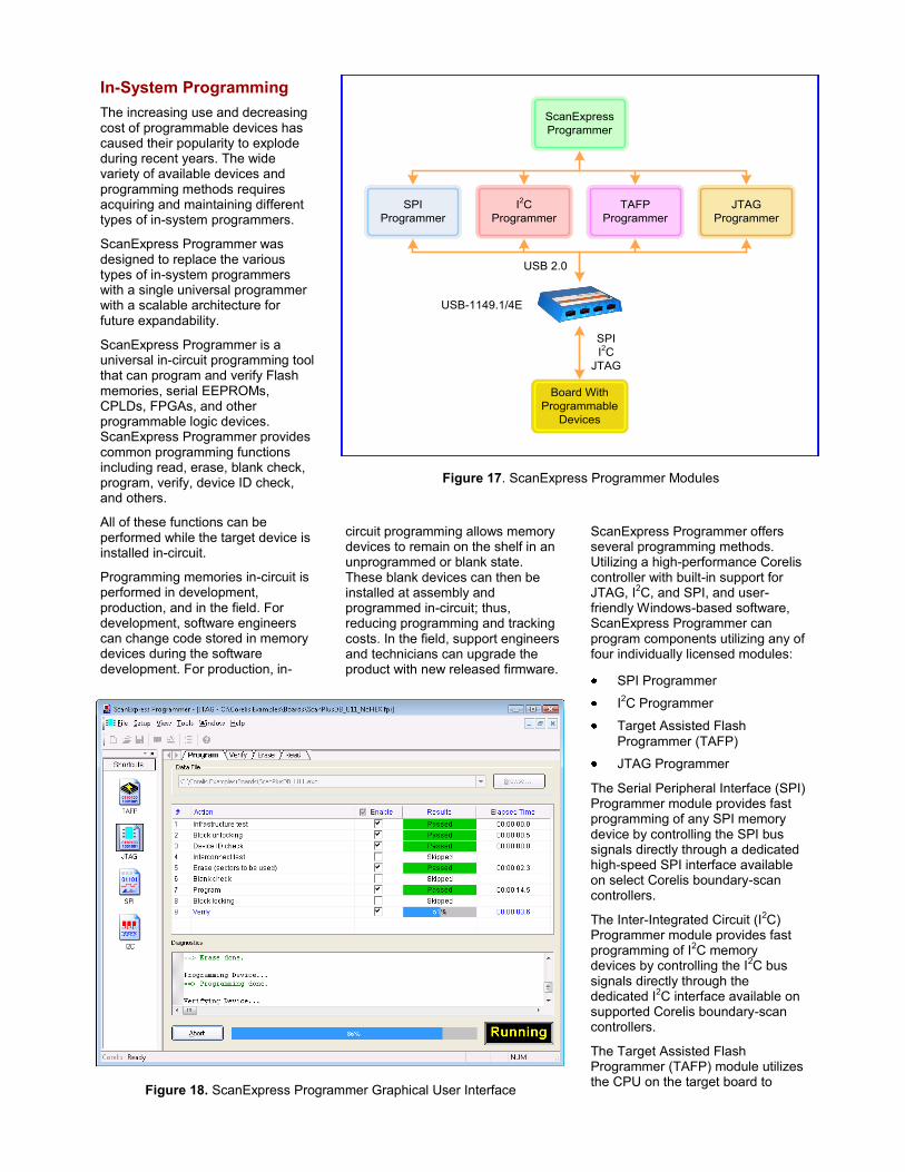
The increasing use and decreasing cost of programmable devices has caused their popularity to explode during recent years. The wide variety of available devices and programming methods requires acquiring and maintaining different types of in-system programmers.
ScanExpress Programmer was designed to replace the various types of in-system programmers with a single universal programmer with a scalable architecture for future expandability.
ScanExpress Programmer is a universal in-circuit programming tool that can program and verify Flash memories, serial EEPROMs, CPLDs, FPGAs, and other programmable logic devices. ScanExpress Programmer provides common programming functions including read, erase, blank check, program, verify, device ID check, and others.
All of these functions can be performed while the target device is installed in-circuit.
Programming memories in-circuit is performed in development, production, and in the field. For development, software engineers can change code stored in memory devices during the software development. For production, in-
circuit programming allows memory devices to remain on the shelf in an unprogrammed or blank state. These blank devices can then be installed at assembly and programmed in-circuit; thus, reducing programming and tracking costs. In the field, support engineers and technicians can upgrade the product with new released firmware.
ScanExpress Programmer offers several programming methods. Utilizing a high-performance Corelis controller with built-in support for JTAG, I2C, and SPI, and user-friendly Windows-based software, ScanExpress Programmer can program components utilizing any of four individually licensed modules:
SPI Programmer
I2C Programmer
Target Assisted Flash
Programmer (TAFP)
JTAG Programmer
The Serial Peripheral Interface (SPI) Programmer module provides fast programming of any SPI memory device by controlling the SPI bus signals directly through a dedicated high-speed SPI interface available on select Corelis boundary-scan controllers.
The Inter-Integrated Circuit (I2C) Programmer module provides fast programming of I2C memory devices by controlling the I2C bus signals directly through the dedicated I2C interface available on supported Corelis boundary-scan controllers.
The Target Assisted Flash Programmer (TAFP) module utilizes the CPU on the target board to
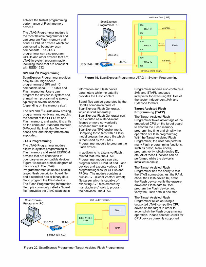
Figure 18. ScanExpress Programmer Graphical User Interface
Figure 17. ScanExpress Programmer Modules
TAFP
Programmer
ScanExpress
Programmer
USB 2.0
SPI
Programmer
JTAG
Programmer
I2C
Programmer
USB-1149.1/4E
Board With
Programmable
Devices
SPI
I2C
JTAG
achieve the fastest programming performance of Flash memory devices.
The JTAG Programmer module is the most flexible programmer and can program Flash memory and serial EEPROM devices which are connected to boundary-scan components. The JTAG programmer can also program CPLDs and other devices that are JTAG in-system programmable, including those that are compliant with IEEE-1532.
SPI and I2C Programming
ScanExpress Programmer provides easy-to-use, high-speed programming of SPI and I2C compatible serial EEPROMs and Flash memories. Users can program the devices in-system and at maximum programming speed, typically in several seconds (depending on the memory size).
The SPI and I2C GUIs allow erasing, programming, verifying, and reading the content of the EEPROM and Flash memory, and saving it to a file on the computer. Standard Motorola S-Record file, Intel Hex file, text-based hex, and binary formats are supported.
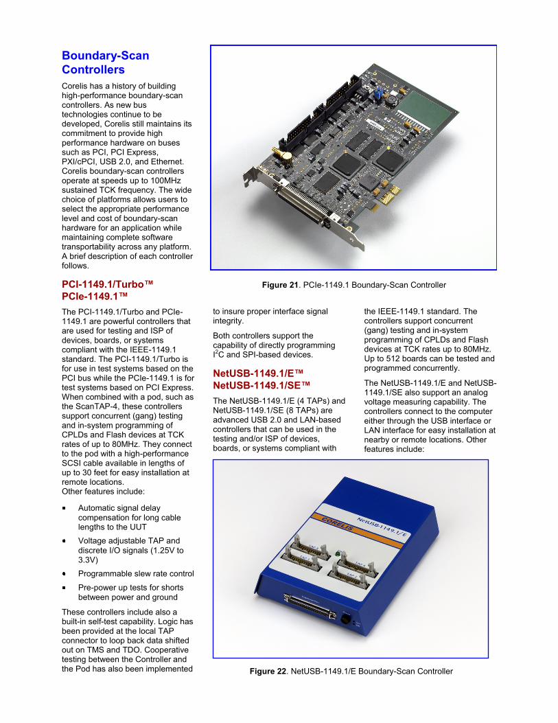
JTAG Programming
The JTAG Programmer module allows in-system programming of Flash memory and serial EEPROM devices that are connected to boundary-scan compatible devices. Figure 19 depicts a block diagram of this concept. The JTAG Programmer module uses a special target Flash description board file and a standard hex or binary data file to program the Flash device. The Flash Programming Information file (.fpi), commonly called a “board file,” provides the JTAG scan chain
information and Flash device parameters while the data file provides the Flash content.
Board files can be generated by the Corelis companion product, ScanExpress Flash Generator, which is sold separately. ScanExpress Flash Generator can be executed as a stand-alone license or more conveniently accessed from within the ScanExpress TPG environment. Compiling these files with a Flash model creates the board file which is then used by the JTAG Programmer module to program the Flash device.
In addition to its extensive Flash-related features, the JTAG Programmer module can also program serial EEPROM and Flash devices and execute various ISP programming files for CPLDs and FPGAs. The module contains a built-in SVF (Serial Vector Format) file parser which is capable of executing SVF files created by manufacturers’ tools to program their devices. The JTAG
Programmer module also contains a JAM and STAPL language interpreter for executing ISP files of the vector-independent JAM and Bytecode formats.
Target Assisted Flash
Programming (TAFP)
The Target Assisted Flash Programmer takes advantage of the embedded CPU on the target board to shorten the Flash memory programming time and simplify the operation of Flash programming. With the Target Assisted Flash Programmer, the user can perform many Flash programming functions, such as erase, blank check, program, verify, obtain device ID, etc. All of these functions can be performed while the device is installed in-circuit.
The Target Assisted Flash Programmer has the ability to test the JTAG connection, test the RAM, check the Flash device ID, erase the Flash device, verify the erasure, download Flash data to RAM, program the Flash device, and verify the Flash data in one step.
The Target Assisted Flash Programmer relies on using a supported JTAG compatible CPU device on the target in order to accomplish the Flash programming operation. Please contact Corelis for CPU devices currently supported.
Figure 20. ScanExpress Programmer Target Assisted Flash Programming
Figure 19. ScanExpress Programmer JTAG In-System Programming
`USB 2.0
USB-1149.1/4E
ScanExpress
Programmer PC
JTAG
Unit Under Test (UUT)
Flash
RAM
IEEE-1149.1
CPU
`
USB 2.0
USB-1149.1/4E
ScanExpress
Programmer PC
Unit Under Test (UUT)
Flash
JTAG IC
TDO
TDI
JTAG IC
TDO
TDI
JTAG IC
TDO
TDI
DATA
ADDRESS
CONTROL
OPTIONAL WRITE SIGNAL
JTAG
Boundary-Scan
Controllers
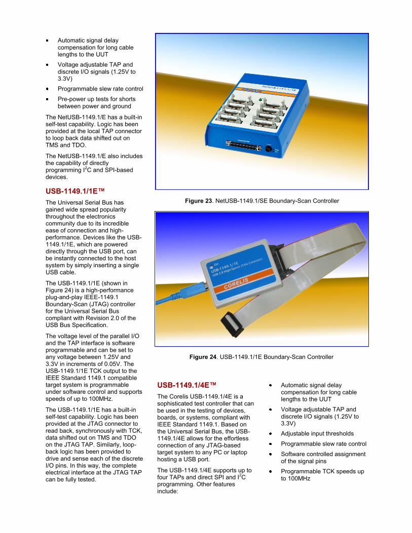
Corelis has a history of building high-performance boundary-scan controllers. As new bus technologies continue to be developed, Corelis still maintains its commitment to provide high performance hardware on buses such as PCI, PCI Express, PXI/cPCI, USB 2.0, and Ethernet. Corelis boundary-scan controllers operate at speeds up to 100MHz sustained TCK frequency. The wide choice of platforms allows users to select the appropriate performance level and cost of boundary-scan hardware for an application while maintaining complete software transportability across any platform. A brief description of each controller follows.
PCI-1149.1/Turbo™
PCIe-1149.1™
The PCI-1149.1/Turbo and PCIe-1149.1 are powerful controllers that are used for testing and ISP of devices, boards, or systems compliant with the IEEE-1149.1 standard. The PCI-1149.1/Turbo is for use in test systems based on the PCI bus while the PCIe-1149.1 is for test systems based on PCI Express. When combined with a pod, such as the ScanTAP-4, these controllers support concurrent (gang) testing and in-system programming of CPLDs and Flash devices at TCK rates of up to 80MHz. They connect to the pod with a high-performance SCSI cable available in lengths of up to 30 feet for easy installation at remote locations. Other features include:
Automatic signal delay
compensation for long cable lengths to the UUT
Voltage adjustable TAP and
discrete I/O signals (1.25V to 3.3V)
Programmable slew rate control
Pre-power up tests for shorts
between power and ground
These controllers include also a built-in self-test capability. Logic has been provided at the local TAP connector to loop back data shifted out on TMS and TDO. Cooperative testing between the Controller and the Pod has also been implemented
to insure proper interface signal integrity.
Both controllers support the capability of directly programming I2C and SPI-based devices.
NetUSB-1149.1/E™
NetUSB-1149.1/SE™
The NetUSB-1149.1/E (4 TAPs) and NetUSB-1149.1/SE (8 TAPs) are advanced USB 2.0 and LAN-based controllers that can be used in the testing and/or ISP of devices, boards, or systems compliant with
the IEEE-1149.1 standard. The controllers support concurrent (gang) testing and in-system programming of CPLDs and Flash devices at TCK rates up to 80MHz. Up to 512 boards can be tested and programmed concurrently.
The NetUSB-1149.1/E and NetUSB-1149.1/SE also support an analog voltage measuring capability. The controllers connect to the computer either through the USB interface or LAN interface for easy installation at nearby or remote locations. Other features include:
Figure 22. NetUSB-1149.1/E Boundary-Scan Controller
Figure 21. PCIe-1149.1 Boundary-Scan Controller
Automatic signal delay
compensation for long cable lengths to the UUT
Voltage adjustable TAP and
discrete I/O signals (1.25V to 3.3V)
Programmable slew rate control
Pre-power up tests for shorts
between power and ground
The NetUSB-1149.1/E has a built-in self-test capability. Logic has been provided at the local TAP connector to loop back data shifted out on TMS and TDO.
The NetUSB-1149.1/E also includes the capability of directly programming I
2C and SPI-based
devices.
USB-1149.1/1E™
The Universal Serial Bus has gained wide spread popularity throughout the electronics community due to its incredible ease of connection and high-performance. Devices like the USB-1149.1/1E, which are powered directly through the USB port, can be instantly connected to the host system by simply inserting a single USB cable.
The USB-1149.1/1E (shown in Figure 24) is a high-performance plug-and-play IEEE-1149.1 Boundary-Scan (JTAG) controller for the Universal Serial Bus compliant with Revision 2.0 of the USB Bus Specification.
The voltage level of the parallel I/O and the TAP interface is software programmable and can be set to any voltage between 1.25V and 3.3V in increments of 0.05V. The USB-1149.1/1E TCK output to the IEEE Standard 1149.1 compatible target system is programmable under software control and supports speeds of up to 100MHz.
The USB-1149.1/1E has a built-in self-test capability. Logic has been provided at the JTAG connector to read back, synchronously with TCK, data shifted out on TMS and TDO on the JTAG TAP. Similarly, loop-back logic has been provided to drive and sense each of the discrete I/O pins. In this way, the complete electrical interface at the JTAG TAP can be fully tested.
USB-1149.1/4E™
The Corelis USB-1149.1/4E is a sophisticated test controller that can be used in the testing of devices, boards, or systems, compliant with IEEE Standard 1149.1. Based on the Universal Serial Bus, the USB-1149.1/4E allows for the effortless connection of any JTAG-based target system to any PC or laptop hosting a USB port.
The USB-1149.1/4E supports up to four TAPs and direct SPI and I2C programming. Other features include:
Automatic signal delay
compensation for long cable lengths to the UUT
Voltage adjustable TAP and
discrete I/O signals (1.25V to 3.3V)
Adjustable input thresholds
Programmable slew rate control
Software controlled assignment
of the signal pins
Programmable TCK speeds up
to 100MHz
Figure 24. USB-1149.1/1E Boundary-Scan Controller
Figure 23. NetUSB-1149.1/SE Boundary-Scan Controller
The USB-1149.1/4E also has built-in self-test capability. Logic has been provided at each I/O pin to loop back the signals from the target connector.
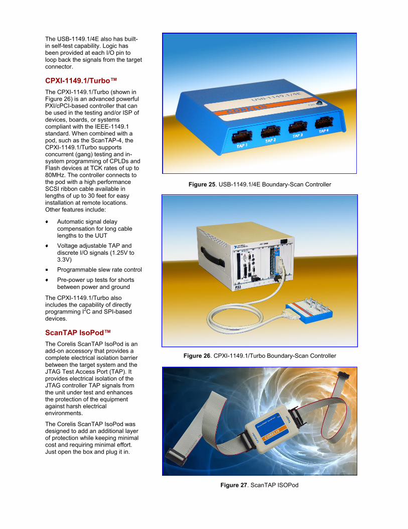
CPXI-1149.1/Turbo™
The CPXI-1149.1/Turbo (shown in Figure 26) is an advanced powerful PXI/cPCI-based controller that can be used in the testing and/or ISP of devices, boards, or systems compliant with the IEEE-1149.1 standard. When combined with a pod, such as the ScanTAP-4, the CPXI-1149.1/Turbo supports concurrent (gang) testing and in-system programming of CPLDs and Flash devices at TCK rates of up to 80MHz. The controller connects to the pod with a high performance SCSI ribbon cable available in lengths of up to 30 feet for easy installation at remote locations. Other features include:
Automatic signal delay
compensation for long cable lengths to the UUT
Voltage adjustable TAP and
discrete I/O signals (1.25V to 3.3V)
Programmable slew rate control
Pre-power up tests for shorts
between power and ground
The CPXI-1149.1/Turbo also includes the capability of directly programming I2C and SPI-based devices.
ScanTAP IsoPod™
The Corelis ScanTAP IsoPod is an add-on accessory that provides a complete electrical isolation barrier between the target system and the JTAG Test Access Port (TAP). It provides electrical isolation of the JTAG controller TAP signals from the unit under test and enhances the protection of the equipment against harsh electrical environments.
The Corelis ScanTAP IsoPod was designed to add an additional layer of protection while keeping minimal cost and requiring minimal effort. Just open the box and plug it in.
Figure 26. CPXI-1149.1/Turbo Boundary-Scan Controller
Figure 25. USB-1149.1/4E Boundary-Scan Controller
Figure 27. ScanTAP ISOPod
Low Voltage Adapter
The Low Voltage Adapter add-on accessory connects to Corelis scan controllers to provide an active, plug-in interface to low voltage scan chains. The compact adapter automatically detects and matches UUT reference voltages between 0.4V and 2.5V on the UUT connector pin and is capable of driving output signals up to 90 mA, readily accommodating 50 ohm loads at up to 100 MHz TCK rates.
The Low Voltage adapter connects to standard 60-pin BSH sockets and is designed to interface directly with Intel XDP, XDP-Sinned, and ITP700 Flex small form factor connectors.
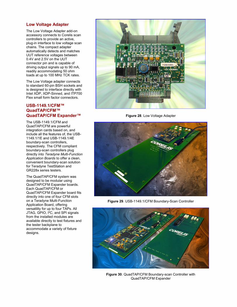
USB-1149.1/CFM™ QuadTAP/CFM™
QuadTAP/CFM Expander™
The USB-1149.1/CFM and QuadTAP/CFM are powerful integration cards based on, and include all the features of, the USB-1149.1/1E and USB-1149.1/4E boundary-scan controllers, respectively. The CFM compliant boundary-scan controllers plug directly into Teradyne Multi-Function Application Boards to offer a clean, convenient boundary-scan solution for Teradyne TestStation and GR228x series testers.
The QuadTAP/CFM system was designed to be modular using QuadTAP/CFM Expander boards. Each QuadTAP/CFM or QuadTAP/CFM Expander board fits directly into one of four CFM slots on a Teradyne Multi-Function Application Board, offering versatility for up to four TAPs. All JTAG, GPIO, I²C, and SPI signals from the installed modules are available directly to test fixtures and the tester backplane to accommodate a variety of fixture designs.
Figure 29. USB-1149.1/CFM Boundary-Scan Controller
Figure 28. Low Voltage Adapter
Figure 30. QuadTAP/CFM Boundary-scan Controller with QuadTAP/CFM Expander
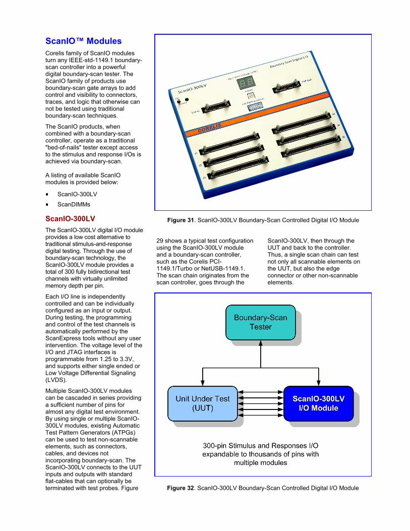
ScanIO™ Modules
Corelis family of ScanIO modules turn any IEEE-std-1149.1 boundary-scan controller into a powerful digital boundary-scan tester. The ScanIO family of products use boundary-scan gate arrays to add control and visibility to connectors, traces, and logic that otherwise can not be tested using traditional boundary-scan techniques.
The ScanIO products, when combined with a boundary-scan controller, operate as a traditional "bed-of-nails" tester except access to the stimulus and response I/Os is achieved via boundary-scan. A listing of available ScanIO modules is provided below:
ScanIO-300LV
ScanDIMMs
ScanIO-300LV
The ScanIO-300LV digital I/O module provides a low cost alternative to traditional stimulus-and-response digital testing. Through the use of boundary-scan technology, the ScanIO-300LV module provides a total of 300 fully bidirectional test channels with virtually unlimited memory depth per pin.
Each I/O line is independently controlled and can be individually configured as an input or output. During testing, the programming and control of the test channels is automatically performed by the ScanExpress tools without any user intervention. The voltage level of the I/O and JTAG interfaces is programmable from 1.25 to 3.3V, and supports either single ended or Low Voltage Differential Signaling (LVDS).
Multiple ScanIO-300LV modules can be cascaded in series providing a sufficient number of pins for almost any digital test environment. By using single or multiple ScanIO-300LV modules, existing Automatic Test Pattern Generators (ATPGs) can be used to test non-scannable elements, such as connectors, cables, and devices not incorporating boundary-scan. The ScanIO-300LV connects to the UUT inputs and outputs with standard flat-cables that can optionally be terminated with test probes. Figure
29 shows a typical test configuration using the ScanIO-300LV module and a boundary-scan controller, such as the Corelis PCI-1149.1/Turbo or NetUSB-1149.1. The scan chain originates from the scan controller, goes through the
ScanIO-300LV, then through the UUT and back to the controller. Thus, a single scan chain can test not only all scannable elements on the UUT, but also the edge connector or other non-scannable elements.
Figure 31. ScanIO-300LV Boundary-Scan Controlled Digital I/O Module
Figure 32. ScanIO-300LV Boundary-Scan Controlled Digital I/O Module
For complete information on the ScanIO-300LV, please refer to the detailed data sheet for this product.
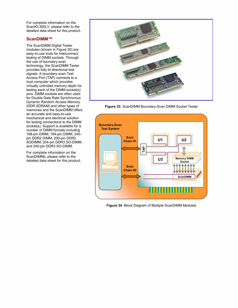
ScanDIMM™
The ScanDIMM Digital Tester modules (shown in Figure 30) are easy-to-use tools for interconnect testing of DIMM sockets. Through the use of boundary-scan technology, the ScanDIMM Tester provides fully bi-directional test signals. A boundary-scan Test Access Port (TAP) connects to a host computer which provides virtually unlimited memory depth for testing each of the DIMM socket(s) pins. DIMM sockets are often used for Double Data Rate Synchronous Dynamic Random Access Memory (DDR SDRAM) and other types of memories and the ScanDIMM offers an accurate and easy-to-use mechanical and electrical solution for testing connections to the DIMM socket(s). Support is available for a number of DIMM formats including 168-pin DIMM, 184-pin DIMM, 240-pin DDR2 DIMM, 200-pin DDR2 SODIMM, 204-pin DDR3 SO-DIMM, and 240-pin DDR3 SO-DIMM.
For complete information on the ScanDIMMs, please refer to the detailed data sheet for this product.
Figure 33. ScanDIMM Boundary-Scan DIMM Socket Tester
ScanDIMM-184
U2U1
Memory DIMM
SocketU3
TA
P
Boundary-Scan
Test System
Scan
Chain #1
Scan
Chain #2
ScanDIMM
Figure 34. Block Diagram of Multiple ScanDIMM Modules
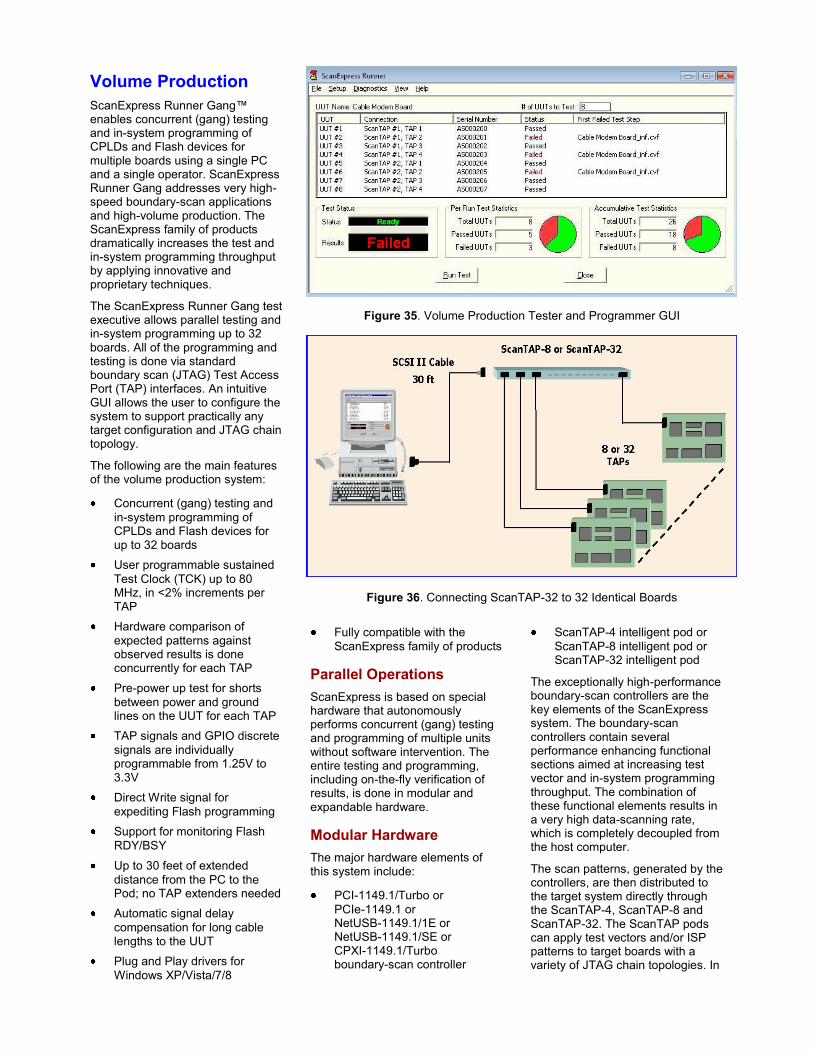
Volume Production
ScanExpress Runner Gang™ enables concurrent (gang) testing and in-system programming of CPLDs and Flash devices for multiple boards using a single PC and a single operator. ScanExpress Runner Gang addresses very high-speed boundary-scan applications and high-volume production. The ScanExpress family of products dramatically increases the test and in-system programming throughput by applying innovative and proprietary techniques.
The ScanExpress Runner Gang test executive allows parallel testing and in-system programming up to 32 boards. All of the programming and testing is done via standard boundary scan (JTAG) Test Access Port (TAP) interfaces. An intuitive GUI allows the user to configure the system to support practically any target configuration and JTAG chain topology.
The following are the main features of the volume production system:
Concurrent (gang) testing and
in-system programming of CPLDs and Flash devices for up to 32 boards
User programmable sustained
Test Clock (TCK) up to 80 MHz, in <2% increments per TAP
Hardware comparison of
expected patterns against observed results is done concurrently for each TAP
Pre-power up test for shorts
between power and ground lines on the UUT for each TAP
TAP signals and GPIO discrete
signals are individually programmable from 1.25V to 3.3V
Direct Write signal for
expediting Flash programming
Support for monitoring Flash
RDY/BSY
Up to 30 feet of extended
distance from the PC to the Pod; no TAP extenders needed
Automatic signal delay
compensation for long cable lengths to the UUT
Plug and Play drivers for
Windows XP/Vista/7/8
Figure 35. Volume Production Tester and Programmer GUI
Figure 36. Connecting ScanTAP-32 to 32 Identical Boards
Fully compatible with the
ScanExpress family of products
Parallel Operations
ScanExpress is based on special hardware that autonomously performs concurrent (gang) testing and programming of multiple units without software intervention. The entire testing and programming, including on-the-fly verification of results, is done in modular and expandable hardware.
Modular Hardware
The major hardware elements of this system include:
PCI-1149.1/Turbo or
PCIe-1149.1 or NetUSB-1149.1/1E or NetUSB-1149.1/SE or CPXI-1149.1/Turbo boundary-scan controller
ScanTAP-4 intelligent pod or
ScanTAP-8 intelligent pod or ScanTAP-32 intelligent pod
The exceptionally high-performance boundary-scan controllers are the key elements of the ScanExpress system. The boundary-scan controllers contain several performance enhancing functional sections aimed at increasing test vector and in-system programming throughput. The combination of these functional elements results in a very high data-scanning rate, which is completely decoupled from the host computer.
The scan patterns, generated by the controllers, are then distributed to the target system directly through the ScanTAP-4, ScanTAP-8 and ScanTAP-32. The ScanTAP pods can apply test vectors and/or ISP patterns to target boards with a variety of JTAG chain topologies. In
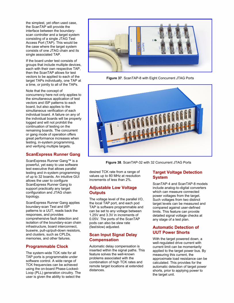
Figure 37. ScanTAP-8 with Eight Concurrent JTAG Ports
Figure 38. ScanTAP-32 with 32 Concurrent JTAG Ports
the simplest, yet often used case, the ScanTAP will provide the interface between the boundary-scan controller and a target system consisting of a single JTAG Test Access Port (TAP). This would be the case where the target system consists of one JTAG chain and its single associated TAP.
If the board under test consists of groups that include multiple devices, each with their own respective TAP, then the ScanTAP allows for test vectors to be applied to each of the target TAPs individually, one TAP at a time, or jointly to all of the TAPs.
Note that the concept of concurrency here not only applies to the simultaneous application of test vectors and ISP patterns to each board, but also applies to the simultaneous verification of each individual board. A failure on any of the individual boards will be properly logged and will not prohibit the continuation of testing on the remaining boards. The concurrent or gang mode of operation offers great performance increases when testing, in-system programming, and verifying multiple targets.
ScanExpress Runner Gang
ScanExpress Runner Gang™ is a powerful, yet easy to use software test executive that allows parallel testing and in-system programming of up to 32 boards. An intuitive GUI allows the user to configure ScanExpress Runner Gang to support practically any target configuration and JTAG chain topology.
ScanExpress Runner Gang applies boundary-scan Test and ISP patterns to a UUT, reads back the responses, and provides comprehensive fault detection and isolation of the boundary-scan chain infrastructure, board interconnect, buswire, pull-up/pull-down resistors, and clusters, such as CPLDs, memories, and other failures.
Programmable Clock
The system-wide TCK rate for all TAP ports is programmable under software control. A wide range of TCK frequencies can be achieved using the on-board Phase-Locked-Loop (PLL) generation circuitry. The user is given the ability to select the
desired TCK rate from a range of values up to 80 MHz at resolution increments of less than 2%.
Adjustable Low Voltage
Outputs
The voltage level of the parallel I/O, the local TAP port, and each pod TAP is software programmable and can be set to any voltage between 1.25V and 3.3V in increments of 0.05V. The ports of the ScanTAP pods can also be slew rate (fast/slow) adjusted.
Scan Input Signal Delay
Compensation
Automatic delay compensation is inserted within the signal paths. This feature solves the well-known problems associated with the combination of high TCK rates and remote target locations at extended distances.
Target Voltage Detection
System
ScanTAP-4 and ScanTAP-8 models include analog-to-digital converters which can measure connected power voltages from the target. Such voltages from two distinct target levels can be measured and compared against user-defined limits. This feature can provide detailed signal voltage checks at any stage of a test plan.
Automatic Detection of
UUT Power Shorts
With the target powered down, a well-regulated drive current with current limit can be momentarily applied to the target power bus. By measuring this current, the approximate load resistance can be calculated. This provides for the automatic detection of target power shorts, prior to applying power to the target unit.
Functional Test
Today, board tests utilize a high degree of boundary-scan tests followed by a functional real-time test including analog tests.
To combine boundary-scan tests with functional tests and run them more efficiently, Corelis is offering two ways to execute the combined tests. Users can execute the tests either from their Test Executive of choice or use the Corelis ScanExpress Runner GUI.
Third party Applications
ScanExpress Runner can execute boundary-scan tests and various ISP files from third party applications using DLLs or a command line interface. Drivers for the popular National Instruments TestStand, LabWindows/CVI, LabVIEW, and Agilent VEE test environments are provided as part of the standard product. A generic command-line based interface is also available for executing ScanExpress Runner Test Step files from any third party application that supports execution of external programs.
The Corelis Application Note series “Using the ScanExpress Runner DLL” has detailed information on how to use ScanExpress Runner with many popular third party test executives and programming languages, such as Visual Basic, Visual C++, and more.
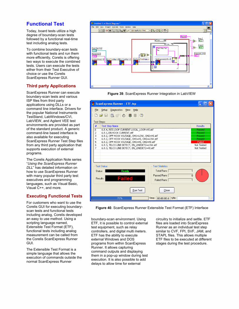
Executing Functional Tests
For customers who want to use the Corelis GUI for executing boundary-scan tests and functional tests including analog, Corelis developed an easy to use method. Using a scripting language named, Extensible Test Format (ETF), functional tests including analog measurement can be called from the Corelis ScanExpress Runner GUI.
The Extensible Test Format is a simple language that allows the execution of commands outside the normal ScanExpress Runner
boundary-scan environment. Using ETF, it is possible to control external test equipment, such as relay controllers, and digital multi meters. ETF has the ability to execute external Windows and DOS programs from within ScanExpress Runner. It allows capturing command outputs and displaying them in a pop-up window during test execution. It is also possible to add delays to allow time for external
circuitry to initialize and settle. ETF files are loaded into ScanExpress Runner as an individual test step similar to CVF, FPI, SVF, JAM, and STAPL files. This allows multiple ETF files to be executed at different stages during the test procedure.
Figure 39. ScanExpress Runner Integration in LabVIEW
Figure 40. ScanExpress Runner Extensible Test Format (ETF) Interface
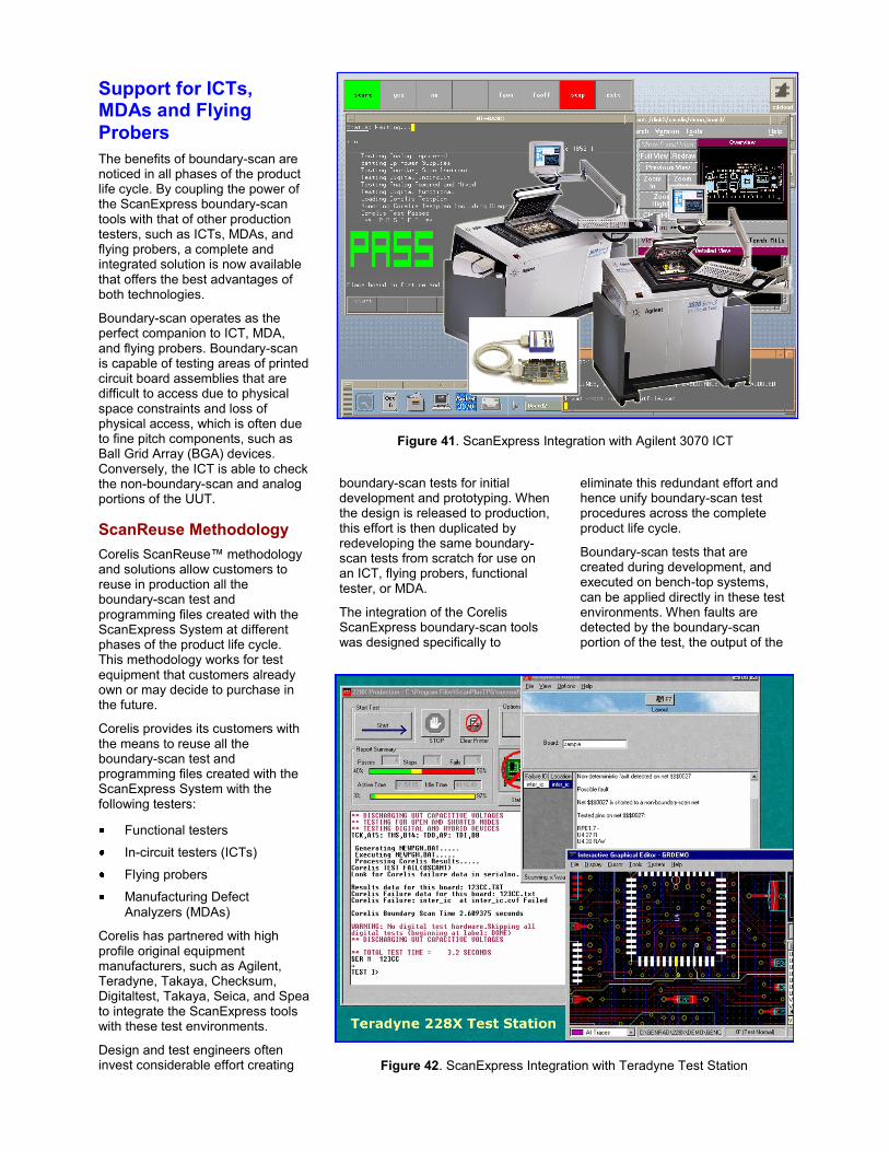
Support for ICTs, MDAs and Flying
Probers
The benefits of boundary-scan are noticed in all phases of the product life cycle. By coupling the power of the ScanExpress boundary-scan tools with that of other production testers, such as ICTs, MDAs, and flying probers, a complete and integrated solution is now available that offers the best advantages of both technologies.
Boundary-scan operates as the perfect companion to ICT, MDA, and flying probers. Boundary-scan is capable of testing areas of printed circuit board assemblies that are difficult to access due to physical space constraints and loss of physical access, which is often due to fine pitch components, such as Ball Grid Array (BGA) devices. Conversely, the ICT is able to check the non-boundary-scan and analog portions of the UUT.
ScanReuse Methodology
Corelis ScanReuse™ methodology and solutions allow customers to reuse in production all the boundary-scan test and programming files created with the ScanExpress System at different phases of the product life cycle. This methodology works for test equipment that customers already own or may decide to purchase in the future.
Corelis provides its customers with the means to reuse all the boundary-scan test and programming files created with the ScanExpress System with the following testers:
Functional testers
In-circuit testers (ICTs)
Flying probers
Manufacturing Defect
Analyzers (MDAs)
Corelis has partnered with high profile original equipment manufacturers, such as Agilent, Teradyne, Takaya, Checksum, Digitaltest, Takaya, Seica, and Spea to integrate the ScanExpress tools with these test environments.
Design and test engineers often invest considerable effort creating
boundary-scan tests for initial development and prototyping. When the design is released to production, this effort is then duplicated by redeveloping the same boundary-scan tests from scratch for use on an ICT, flying probers, functional tester, or MDA.
The integration of the Corelis ScanExpress boundary-scan tools was designed specifically to
eliminate this redundant effort and hence unify boundary-scan test procedures across the complete product life cycle.
Boundary-scan tests that are created during development, and executed on bench-top systems, can be applied directly in these test environments. When faults are detected by the boundary-scan portion of the test, the output of the
Figure 41. ScanExpress Integration with Agilent 3070 ICT
Figure 42. ScanExpress Integration with Teradyne Test Station
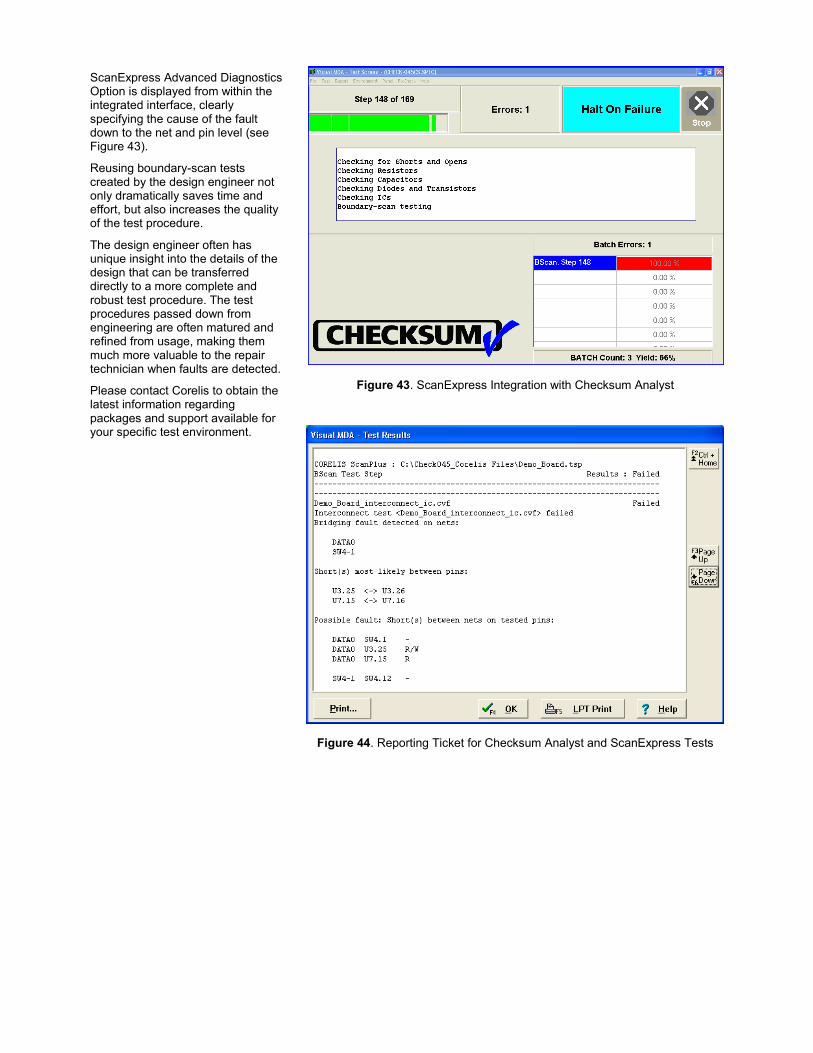
ScanExpress Advanced Diagnostics Option is displayed from within the integrated interface, clearly specifying the cause of the fault down to the net and pin level (see Figure 43).
Reusing boundary-scan tests created by the design engineer not only dramatically saves time and effort, but also increases the quality of the test procedure.
The design engineer often has unique insight into the details of the design that can be transferred directly to a more complete and robust test procedure. The test procedures passed down from engineering are often matured and refined from usage, making them much more valuable to the repair technician when faults are detected.
Please contact Corelis to obtain the latest information regarding packages and support available for your specific test environment.
Figure 43. ScanExpress Integration with Checksum Analyst
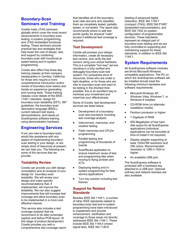
Figure 44. Reporting Ticket for Checksum Analyst and ScanExpress Tests
Boundary-Scan
Seminars and Training
Corelis hosts JTAG seminars globally which cover the most recent advancements in boundary-scan testing, in-system programming, and JTAG embedded functional testing. These seminars provide practical tips and strategies that help lower the cost of design, test, and support by combining boundary-scan with functional at-speed testing and in-system programming.
Corelis also offers free three-day training classes at their company headquarters in Cerritos, California for those who require a more comprehensive introduction and/or review of boundary-scan basics and hands-on experience generating and running tests. These training classes cover details of the IEEE-1149.1 standard, design for boundary-scan testability (DFT), ISP guidelines, the boundary-scan description language (BSDL), current relevant test topics, demonstrations, and hands-on ScanExpress software training using demonstration hardware.
Engineering Services
If you are new to boundary-scan, would like assistance with any aspect of implementing boundary-scan testing in your design, or are simply short of resources at present, we can help you. The following are some of the services that we provide:
Testability Review
Corelis can provide you with design consultation and an analysis of your design for boundary-scan testability. We will review your design and make specific recommendations that, if implemented, will improve the testability. We can also suggest improvements that will increase test coverage and allow boundary-scan to be implemented in a more cost-effective manner.
This service also includes a test coverage analysis that we recommend to do after schematic capture and before PCB layout. At this stage of product development, Corelis provides you with a comprehensive test coverage report
that identifies all of the boundary-scan nets and pins and classifies them as completely tested, partially tested, or not tested. The report also recommends where to add test points (pads) for physical "nails" access if additional test coverage is required.
Test Development
Corelis will process your design information, create all necessary test vectors, and verify the test vectors using your actual hardware. This is a complete "turn-key" service resulting in a fully verified and debugged boundary-scan test system. For companies short of resources, those who are under a tight deadline, or for those who are new to boundary-scan and want to be testing in the shortest time possible, this is an excellent way to minimize your investment and maximize your effectiveness.
Some of Corelis’ test development services are listed below:
Development of a boundary-
scan test procedure including test coverage analysis
Interconnect, memories, and
clusters testing
Flash memories and CPLDs
programming
Parallel testing and
programming of thousands of boards
ScanReuse application to
ensure maximum reuse of test and programming files when moving to flying probers and ICTs
Deploying testing and in-
system programming for field service applications
Turn key solution including test
fixtures
Support for Related
Standards
Besides IEEE Std 1149.1, a number of other IEEE standards related to boundary-scan test and in-system programming have been introduced to supplement and provide enhancement, clarification and coverage to those areas not directly addressed IEEE Std 1149.1. These include IEEE Std 1149.4 (mixed signal test), IEEE Std 1149.6
(testing of advanced digital networks), IEEE Std 1149.7 (compact JTAG), IEEE Std P1687 (embedded instrumentation), and IEEE Std 1532 (in-system configuration of programmable devices). These standards represent an integral part of boundary-scan testing and we are fully committed to supporting and maintaining support for these standards, in addition to IEEE Std 1149.1.
System Requirements
All ScanExpress software modules are 64-bit Microsoft Windows compatible applications. The PC on which the ScanExpress software will be installed should meet the following minimum hardware and software requirements:
Microsoft Windows XP,
Windows Vista, Windows 7, or Windows 8 installed
CD-ROM drive (or alternate
installation media)
Pentium processor or higher
1 Gigabyte of RAM
650 Megabytes of free hard
disk space for all ScanExpress applications (individual applications can be excluded at time of install if not required)
Display adapter supporting at
least 1024x768 resolution and 256 colors. Recommended resolution is 1280 x 1024 or higher.
An available USB port.
The ScanExpress software is protected with a hardware key attached to a USB port. Optional soft-key and network licenses are also available.
13100 Alondra Blvd. Cerritos, California 90703 Telephone: (562) 926-6727, Fax: (562) 404-6196 [email protected] www.corelis.com
Windows is a registered trademark of Microsoft Corporation.
LabVIEW, Lab Windows/CVI, and NI TestStand are registered trademarks of National Instruments.
Agilent VEE is a registered trademark of Agilent.
PowerPC is a registered trademark of IBM.
ScanExpress, ScanExpress TPG, ScanExpress Runner, ScanExpress Debugger, ScanExpress Flash, ScanExpress Merge, ScanExpress DFT Analyzer, ScanExpress Viewer, ScanExpress ADO, ScanExpress JET, PCI-1149.1/Turbo, PCIe-1149.1, CPXI-1149.1/Turbo, NetUSB-1149.1/1E, USB-1149.1/1E, USB-1149.1/4E, ScanTAP IsoPod, ScanIO, ScanDIMM, ScanReuse, and ScanExpressICT are trademarks of Corelis, Inc.
All other trademarks referred to herein are the property of their respective owner.
© Copyright 1999-2013 by Corelis, Inc. All rights reserved.
Corelis, Inc. reserves the right to make changes in design or specification at any time without notice.
Revision: 02.08.13