Embed Size (px)
Citation preview
Team 5 PDR report Page
Preliminary Design Review (PDR) Wireless Immersive Training Vest Monitoring System
Prepared by SysEng 368 Group 5
Chris Blanchard – [email protected]
Gareth Caunt – [email protected]
Michael Donnerstein – [email protected]
Chris Neuman – [email protected]
Varun Ramachandran – [email protected]
Submitted : November 14th, 2012

Team 5 PDR report Page i
Table of Contents List of Figures ............................................................................................................................................ ii
List of Tables ............................................................................................................................................ iii
Background ................................................................................................................................................... 1
Introduction – Statement of Need ................................................................................................................ 1
Operational View (OV-1) ............................................................................................................................... 2
System Level Requirements (Tier 0) ............................................................................................................. 3
Assumptions .................................................................................................................................................. 4
Feasibility Analysis Overview ........................................................................................................................ 4
Feasibility Analysis and Trade Study ............................................................................................................. 6
Relaying System ........................................................................................................................................ 6
Recording System...................................................................................................................................... 8
Data Analysis ............................................................................................................................................. 9
Feedback Relay to Soldiers ..................................................................................................................... 10
Updated Kiviat Chart ................................................................................................................................... 11
System Level Measures of Effectiveness .................................................................................................... 11
Technical Performance Measurements ...................................................................................................... 13
Functional Analysis and Decomposition ..................................................................................................... 15
Receive Data ........................................................................................................................................... 15
Process Data ............................................................................................................................................ 16
Store Data ............................................................................................................................................... 17
Relay Data ............................................................................................................................................... 18
Receive Data ........................................................................................................................................... 18
Alert Soldier ............................................................................................................................................ 19
Physical Architecture .................................................................................................................................. 20
Functional to Physical Mapping .............................................................................................................. 22
Technical Management Plan ....................................................................................................................... 23
Risk Analysis ................................................................................................................................................ 23
Updated Risk Matrix ............................................................................................................................... 25
Work Breakdown Structure ........................................................................................................................ 29
Cost Estimate .............................................................................................................................................. 30
Schedule ...................................................................................................................................................... 31
Team 5 PDR report Page ii
Support Concept ......................................................................................................................................... 32
Program Management Best Practices (PMBP) ........................................................................................... 36
Appendix A – Technical Management Plan ................................................................................................ 38
Appendix B – Software Development ......................................................................................................... 46
Pseudo Code ........................................................................................................................................... 46
Graphical User Interface (GUI) ................................................................................................................ 47
Appendix C – Operational Feasibility .......................................................................................................... 48
Safety ...................................................................................................................................................... 48
Reliability ................................................................................................................................................. 51
Maintainability ........................................................................................................................................ 56
Availability ............................................................................................................................................... 60
Affordability ............................................................................................................................................ 62
Supportability .......................................................................................................................................... 63
Disposability ............................................................................................................................................ 65
Usability .................................................................................................................................................. 67
Appendix D – Hardware Technical Specifications ....................................................................................... 69
Meshlium Router .................................................................................................................................... 69
Laptop ..................................................................................................................................................... 73
Appendix E: Vendor Communications ....................................................................................................... 74
List of Figures Figure 1: Customer Supplied OV-1 ................................................................................................................ 2
Figure 2: Relay Data Kiviat Chart ................................................................................................................... 7
Figure 3: Data Storage Kiviat Chart ............................................................................................................... 8
Figure 4: Data Analysis Kiviat Chart .............................................................................................................. 9
Figure 5: Feedback Relay Kiviat Chart ......................................................................................................... 10
Figure 6: Measure of Architecture Kiviat Chart .......................................................................................... 11
Figure 7: Measures of effectiveness ........................................................................................................... 12
Figure 8: PDR Functional Decomposition ................................................................................................... 15
Figure 9: Receive Data Function ................................................................................................................. 15
Figure 10: Process Data functions ............................................................................................................... 16
Figure 11: Store Data functions .................................................................................................................. 17
Figure 12: Relay Data functions .................................................................................................................. 18
Figure 13: Receive Data from Trainer functions ......................................................................................... 18
Figure 14: Alert Soldier functions ............................................................................................................... 19
Team 5 PDR report Page iii
Figure 15: System Physical Architecture ..................................................................................................... 20
Figure 16: Risks........................................................................................................................................... 27
Figure 17: Risk consequence assessment table ......................................................................................... 28
Figure 18: Risk likelihood assessment table ............................................................................................... 28
Figure 19: Combined Risk Assessment Table ............................................................................................. 29
Figure 20: Schedule for current phase of project ....................................................................................... 31
Figure 21: Schedule for subsequent phases of project ............................................................................... 32
Figure 22: Preventive Maintenance Flowchart ........................................................................................... 34
Figure 23: In-House Developed GUI ............................................................................................................ 47
Figure 24: Component Interfaces ............................................................................................................... 51
Figure 25: Weibull Probability ..................................................................................................................... 54
Figure 26: Corrective Maintenance Cycle ................................................................................................... 56
Figure 27: Repair Time Distribution ............................................................................................................ 57
Figure 28: Preventative Maintenance Cycle ............................................................................................... 58
Figure 29: Top Level Cost Breakdown Structure ......................................................................................... 62
List of Tables Table 1: Tier 0 Requirements ........................................................................................................................ 3
Table 2: Relay Data ....................................................................................................................................... 7
Table 3: Data Storage .................................................................................................................................... 8
Table 4: Data Analysis ................................................................................................................................... 9
Table 5: Feedback Relay .............................................................................................................................. 10
Table 6: Technical Performance Measures ................................................................................................. 13
Table 7: Replacement Relay Data Element ................................................................................................. 21
Table 8: Tier 0 Mapping .............................................................................................................................. 22
Table 9 System Level Work Breakdown Structure ...................................................................................... 29
Table 10: High Level Cost Breakdown ......................................................................................................... 30
Table 11: Detailed Hardware Costs ............................................................................................................. 30
Table 12: Severity Categories ...................................................................................................................... 49
Table 13: Probability Levels ........................................................................................................................ 49
Table 14: Risk Assessment Matrix ............................................................................................................... 50
Table 15: Life Cycles .................................................................................................................................... 52
Table 16: Estimated MTBF .......................................................................................................................... 52
Table 17: FMECA Example .......................................................................................................................... 54
Table 18: Standard FMECA Rankings .......................................................................................................... 55
Table 19: Typical Maintenance Tasks ......................................................................................................... 59
Table 20: Rolled-Up Sub-Element Costs ..................................................................................................... 63
Table 21: Production Cost Breakdown ....................................................................................................... 63

Team 5 PDR report Page 1
Background
A current reality of the US military is that there are numerous operational arenas around the
world in which its soldiers are put into action. In each military action, soldiers will have to relate with
non-combatant foreign nationals as well as work with their squads in near or full combat situations.
One certainty for the military is that they will constantly be training new troops for deployment into the
field. The problem facing commanding officers is that “new soldiers make errors in-country that cost
lives and Intel opportunities.”
The solution to minimize these mistakes is more intensive training for new troops. A system needs to be
designed that will allow a skilled trainer to monitor up to eight soldiers in training missions and to
provide timely feedback to the soldiers should a combat situation or social faux pas occur. This ‘control
center’ for the trainer must also be able to receive and monitor the vital health statistics for each soldier
so that immediate care can be dispatched if needed.
The system to be developed will receive data from the legacy ITV vest, biotelemetry, and gesture
recognition systems through the Mote system. Data received will be processed and displayed to the
trainer for near-live monitoring and feedback as well as recorded for future debriefing of training
sessions. A legacy developed haptic feedback system will also be integrated for soldier ‘live’ feedback.
Introduction – Statement of Need This paper is provided as supplementary justification to the group 5 PDR presentation that was given
and recorded for the customer on November 8th, 2012. The material in the PDR presentation and this
report was assembled by SYSENG 368 group 5 and is intended to satisfy the need statement given
below.
This project is to design a means to record/relay to a trainer the movements and reactions of
soldiers in a given training environment, allowing for the evaluation or their ability to interact
culturally with non-combatant foreign nationals. The scenario this will be used in will be an
Afghanistan village, although the system must be flexible enough to be applied to other training
scenarios. The information provided to the system will be through a set of legacy equipment as
specified by the Integrated Training Vest (ITV) system. This information is relayed to a trainer in
a control room monitoring a group of up to eight soldiers using the ITV system so that the trainer
can evaluate whether a social faux pas has been committed. The system must be capable of
monitoring, recording, and conveying sufficient information to evaluate the soldiers’
performance within the simulation as well as the health of the soldiers during training. The
overall budget for the development of the system is not to exceed $50001. The system design
1 The budgetary constraint was originally set at $5,000 as represented above. The customer authorized the
expansion of the budget to $10,000 during the conceptual design phase of the project.
Team 5 PDR report Page 2
must be available by December 11 of 2012, and a prototype must be available for integration
into the Missouri Mote system by May 5 of 2013.
The remainder of this paper deals with specific elements of the system as presented in the PDR.
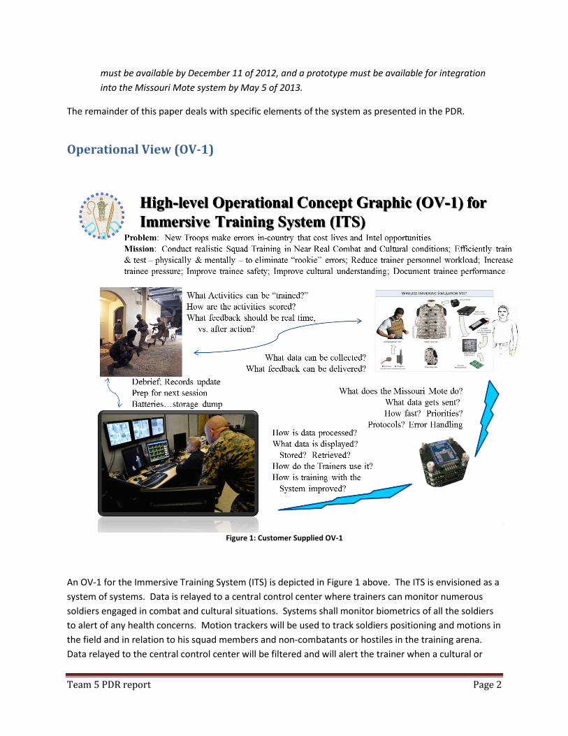
Operational View (OV-1)
Figure 1: Customer Supplied OV-1
An OV-1 for the Immersive Training System (ITS) is depicted in Figure 1 above. The ITS is envisioned as a
system of systems. Data is relayed to a central control center where trainers can monitor numerous
soldiers engaged in combat and cultural situations. Systems shall monitor biometrics of all the soldiers
to alert of any health concerns. Motion trackers will be used to track soldiers positioning and motions in
the field and in relation to his squad members and non-combatants or hostiles in the training arena.
Data relayed to the central control center will be filtered and will alert the trainer when a cultural or

Team 5 PDR report Page 3
combat faux pas occurs. Vital signs shall also be constantly monitored by the trainer. The system shall
be capable of allowing the trainer to send feedback to the soldiers based on a cultural faux pas, combat
faux pas, or health conditions that the system detects. Finally, the system shall store data in a way that
debriefing is streamlined and immediate post-training feedback can be given to the soldier.
System Level Requirements (Tier 0) After reviewing the OV-1 and the statement of need, Team 5 developed a list of requirements. These
requirements were confirmed with our customer Colonel Pape. The Colonel has agreed with the
prioritization of the requirements as listed below. The requirements list below is prioritized from top to
bottom.
Table 1: Tier 0 Requirements
1. The system shall alert the trainer to a medical emergency within 15 seconds 2. The system shall provide sufficient information for a suitably skilled trainer to
monitor the health of the soldiers during training 3. The system shall gauge the criticality of the data being received 4. The system shall prioritize according to the criticality of the data 5. The system shall receive data the prioritized data. 6. The system budget shall be $10,000 or less 7. The system shall interface through the existing legacy equipment specified by the ITV 8. The system shall relay data from the ITV to a control room with a maximum latency
of 500 ms from sensor input to display 9. The system shall monitor data from the equipment in the ITV system available on
project start date in real time 10. Any additions to the ITV must mimic real life mass distributions 11. The system shall record data from ITV 12. The system shall be designed so a trainer can monitor eight (8) soldiers 13. The system shall be able to relay sufficient data for the trainer to evaluate whether a
social faux pas has occurred 14. The system shall relay sufficient data to the trainer to evaluate for whether a ‘Patrol
Tactic/Combat’ faux pas has occurred 15. The system shall alert a suitably skilled trainer to a faux pas within 15 seconds 16. The system reliability over 8 hours shall be 99% 17. The batteries used by the system shall be recycled. 18. The system design must be available by 12-11-2012 19. The system shall have a prototype available by 05-05-13 20. The system shall be operable in an area of 120 sq. ft. to ¼ mile. 21. The system design shall be compatible to the Missouri Mote system available on the
project start date 22. The system shall be adaptable to multiple scenarios
These requirements were analyzed to determine if a solution was feasible within the technical, schedule
and cost constraints. As a result of that analysis, Team 5 firmly believes that a solution is feasible and
there are options available to either increase capability or reduce cost. Some of these were examined
Team 5 PDR report Page 4
during the development of the Conceptual Design Review. The preferred solution is a combination of
the existing items available for the ITV, commercially available hardware and software, and Matlab
developed code to cover any deficiencies present in the existing code.
Assumptions The following is a list of the assumption on which our solution is predicated:
1. Existing mote is integrated with the biotelemetry system
2. Existing mote is integrated with the gesture tracking system
3. Existing mote, biotelemetry system and the gesture tracking system do not impact soldier
safety.
4. Existing mote, biotelemetry system and the gesture tracking system do not alter the weight or
weight distribution for the soldier more than is acceptable to the customer. This facilitates
realistic loading on the soldier during the training exercise.
5. Existing mote, biotelemetry system and the gesture tracking system have their own support and
disposal mechanisms that will not adversely impact our design.
6. Matlab software development is at no cost to Team 5.
7. MST Matlab licenses are suitable for the any development that is required.
8. Virtual Cultural Monitoring System (VCMS) is available for integration into our system.
9. Existing API or example code is available for the mote, biotelemetry system and the VCMS and is
suitable for integration with Matlab.
10. Suitable electrical power is available at the training facility.
Feasibility Analysis Overview After reviewing the customer’s Statement of Need, a group of requirements were developed which are
listed above in Table 1. The scope of the project was further subdivided into four Tier 1 sub-systems.
These consisted of a means of relaying data to the motes to the control room, a system to record
separate data streams for each of the monitored soldiers in the control room, an interface to display the
data received in a meaningful way for the trainer in the control room and a system to allow the trainer
to send feedback to the soldiers using the existing mote network. Criteria that were considered to be
equal among the different options were not included in the initial trade study. As further analysis is
performed, they may be considered as required.
By choosing COTS products, the producibility and disposability aspects of the design are delegated to the
COTS vendors. Electronic waste recycling programs which accept electronics are in place and will
continue to be for the foreseeable future. COTS also address the majority of the supportability aspects
of the design should the solution be installed within the United States. Transportation back to base may
be required should the system be installed in a foreign location. The level of user servicing would be
limited to replacement of failed components and configuring the replacement.
Team 5 PDR report Page 5
The usability of the system will be heavily influenced by the development of the analysis software.
Usability for maintenance staff of the other components will be dependent on their installation in the
training environment. COTS vendors are responsible for the intrinsic safety of their supplies. Installed
locations of components will impact overall safety. Suitable documentation would need to be provided
to ensure that safe use and maintenance can take place.
To determine a more accurate life-cycle cost of the system, the final selection of elements will be
required. Various logistical models can then be used to predict spares requirements. This study does not
offer a complete life-cycle costing.
The key performance parameters considered were:
The number of trainees the system could accommodate. The customer requested at least 8
trainees in the scenario. The customer’s preference was for more. No maximum number of
trainees was stated; however the size of the training area would limit the number of trainees
based on combat faux pas rules. No analysis has been done to determine the maximum number
of trainees in a 120 sq ft area.
Time to alert. This parameter was flexible with the customer providing guidance for the various
different alert scenarios. Medical emergencies required a response in less than 20 seconds and
training errors in less than 60 seconds. Further refinement led to a common timing of 15
seconds.
Size of operational area. The customer requested an area of 120 sq ft to ¼ sq mile.
Trainee equipment weight. The customer need was for the trainee’s equipment weight not to
vary noticeably from a normal combat patrol weight. The IVT will be used in place of the soldier
body armour.
System Cost. The total cost of the system is limited to $10,000 for procurement. Life cycle
costing is to be based on 8 hours training per day, 5 days a week, with 45 weeks a year. The
annual cost of operations including replacements, spare parts and disposal of expended
equipment is not to exceed $50,000.
System Reliability. The reliability of the system should be 99% over an 8 hour training mission.
The customer also indicated that the system should be designed for at least one years life.
Faux Pas detection. The customer requested that the system detect at least 2 but no more than
30 faux pas. This includes both cultural and combat faux pas. Further analysis is required to
determine a suitable list of the faux pas detected. This would need to be worked with the
customer and subject matter experts.
Our solution does not limit the number of soldiers in the training scenario directly. We have a risk that
states the bandwidth available to communicate the trainee action to the control room is the limiting
factor. As stated above, further analysis would be need to done to determine the maximum number of
trainees in the training area that can be accommodated allowing them to move around the area and not
commit a combat faux pas.
Team 5 PDR report Page 6
Our solution does not add any equipment onto the soldier at this stage. This entirely addresses the need
that trainee equipment weight not be significantly increased.
The first pass of the feasibility analysis proved that there were several options that met the customer’s
needs. The selection of our preferred solution was done by further analysis of the options which were
close against the key performance parameters. The sensitivity of the close options to changes in scoring
against these was also assessed. The preferred solution is highlighted below in green. No analysis has
been completed on synergies between the different components of the solution. Further research is
required to obtain relevant information to assess the value of using hardware and software from related
vendors.
Feasibility Analysis and Trade Study
Relaying System (Motes to the Control Room)
Cisco 1552s outdoor access point :
http://www.cisco.com/en/US/prod/collateral/wireless/ps5679/ps11451/ps12440/data_sh
eet_aironet_1552s.pdf
Meshlium ZigBee router
http://www.libelium.com/index.php
National Instruments Wireless Sensor Networks
www.ni.com/wsn
Microstrain gateways and wireless sensors
http://www.microstrain.com/wireless/systems
Missouri Mote system
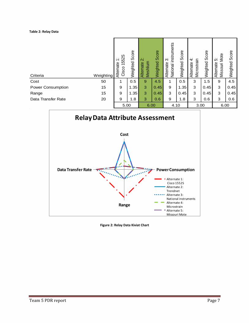
Team 5 PDR report Page 7
Table 2: Relay Data
Criteria Weighting Altern
ate
1:
Cis
co 1
552S
Weig
hte
d S
core
Altern
ate
2:
Meshliu
m
Weig
hte
d S
core
Altern
ate
3:
National in
str
um
ents
Weig
hte
d S
core
Altern
ate
4:
Mic
rostr
ain
Weig
hte
d S
core
Altern
ate
5:
Mis
souri M
ote
Weig
hte
d S
core
Cost 50 1 0.5 9 4.5 1 0.5 3 1.5 9 4.5
Power Consumption 15 9 1.35 3 0.45 9 1.35 3 0.45 3 0.45
Range 15 9 1.35 3 0.45 3 0.45 3 0.45 3 0.45
Data Transfer Rate 20 9 1.8 3 0.6 9 1.8 3 0.6 3 0.6
5.00 6.00 4.10 3.00 6.00
Cost
Power Consumption
Range
Data Transfer Rate
Relay Data Attribute Assessment
Alternate 1:Cisco 1552SAlternate 2:TrendnetAlternate 3:National instrumentsAlternate 4:MicrostrainAlternate 5:Missouri Mote
Figure 2: Relay Data Kiviat Chart
Team 5 PDR report Page 8
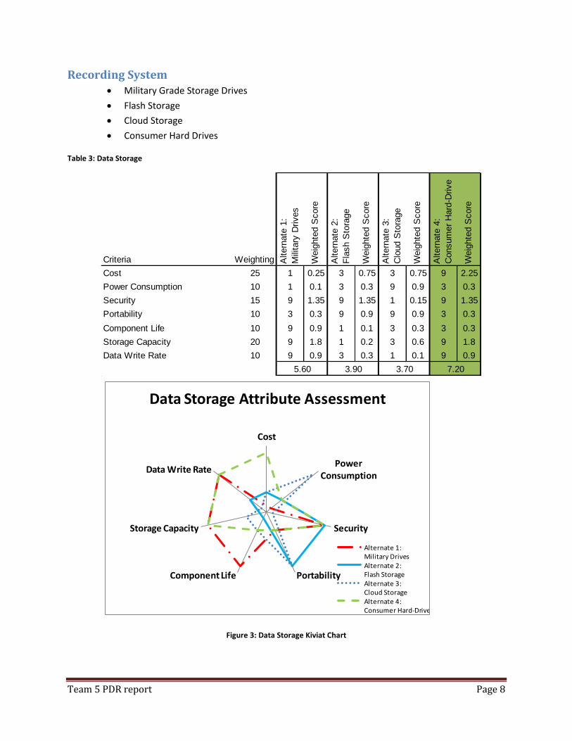
Recording System Military Grade Storage Drives
Flash Storage
Cloud Storage
Consumer Hard Drives
Table 3: Data Storage
Criteria Weighting Altern
ate
1:
Mili
tary
Drives
Weig
hte
d S
core
Altern
ate
2:
Fla
sh S
tora
ge
Weig
hte
d S
core
Altern
ate
3:
Clo
ud S
tora
ge
Weig
hte
d S
core
Altern
ate
4:
Consum
er
Hard
-Drive
Weig
hte
d S
core
Cost 25 1 0.25 3 0.75 3 0.75 9 2.25
Power Consumption 10 1 0.1 3 0.3 9 0.9 3 0.3
Security 15 9 1.35 9 1.35 1 0.15 9 1.35
Portability 10 3 0.3 9 0.9 9 0.9 3 0.3
Component Life 10 9 0.9 1 0.1 3 0.3 3 0.3
Storage Capacity 20 9 1.8 1 0.2 3 0.6 9 1.8
Data Write Rate 10 9 0.9 3 0.3 1 0.1 9 0.9
5.60 3.90 3.70 7.20
Cost
Power Consumption
Security
PortabilityComponent Life
Storage Capacity
Data Write Rate
Data Storage Attribute Assessment
Alternate 1: Military DrivesAlternate 2: Flash StorageAlternate 3: Cloud StorageAlternate 4: Consumer Hard-Drive
Figure 3: Data Storage Kiviat Chart
Team 5 PDR report Page 9
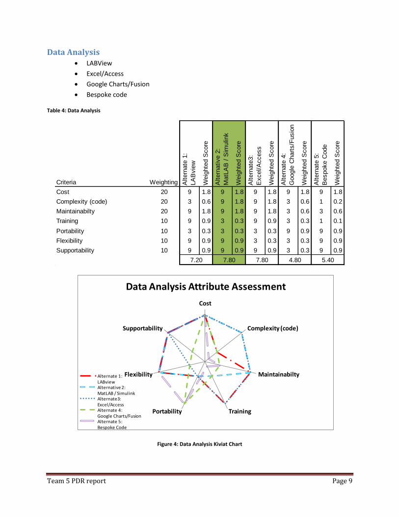
Data Analysis LABView
Excel/Access
Google Charts/Fusion
Bespoke code
Table 4: Data Analysis
Criteria Weighting Altern
ate
1:
LA
Bvie
w
Weig
hte
d S
core
Altern
ative 2
:
MatL
AB
/ S
imulin
k
Weig
hte
d S
core
Altern
ate
3:
Excel/A
ccess
Weig
hte
d S
core
Altern
ate
4:
Chart
s/F
usio
n
Weig
hte
d S
core
Altern
ate
5:
Bespoke C
ode
Weig
hte
d S
core
Cost 20 9 1.8 9 1.8 9 1.8 9 1.8 9 1.8
Complexity (code) 20 3 0.6 9 1.8 9 1.8 3 0.6 1 0.2
Maintainabilty 20 9 1.8 9 1.8 9 1.8 3 0.6 3 0.6
Training 10 9 0.9 3 0.3 9 0.9 3 0.3 1 0.1
Portability 10 3 0.3 3 0.3 3 0.3 9 0.9 9 0.9
Flexibility 10 9 0.9 9 0.9 3 0.3 3 0.3 9 0.9
Supportability 10 9 0.9 9 0.9 9 0.9 3 0.3 9 0.9
5.407.20 7.80 7.80 4.80
Cost
Complexity (code)
Maintainabilty
TrainingPortability
Flexibility
Supportability
Data Analysis Attribute Assessment
Alternate 1:LABviewAlternative 2: MatLAB / SimulinkAlternate3:Excel/AccessAlternate 4: Google Charts/FusionAlternate 5:Bespoke Code
Figure 4: Data Analysis Kiviat Chart
Team 5 PDR report Page 10
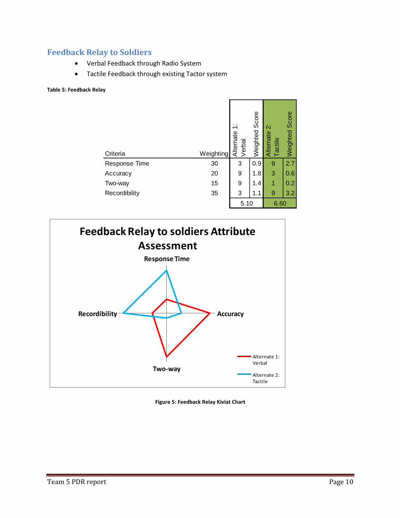
Feedback Relay to Soldiers Verbal Feedback through Radio System
Tactile Feedback through existing Tactor system
Table 5: Feedback Relay
Criteria Weighting Altern
ate
1:
Verb
al
Weig
hte
d S
core
Altern
ate
2:
Tactile
Weig
hte
d S
core
Response Time 30 3 0.9 9 2.7
Accuracy 20 9 1.8 3 0.6
Two-way 15 9 1.4 1 0.2
Recordibility 35 3 1.1 9 3.2
5.10 6.60
Response Time
Accuracy
Two-way
Recordibility
Feedback Relay to soldiers Attribute Assessment
Alternate 1: Verbal
Alternate 2: Tactile
Figure 5: Feedback Relay Kiviat Chart
Team 5 PDR report Page 11
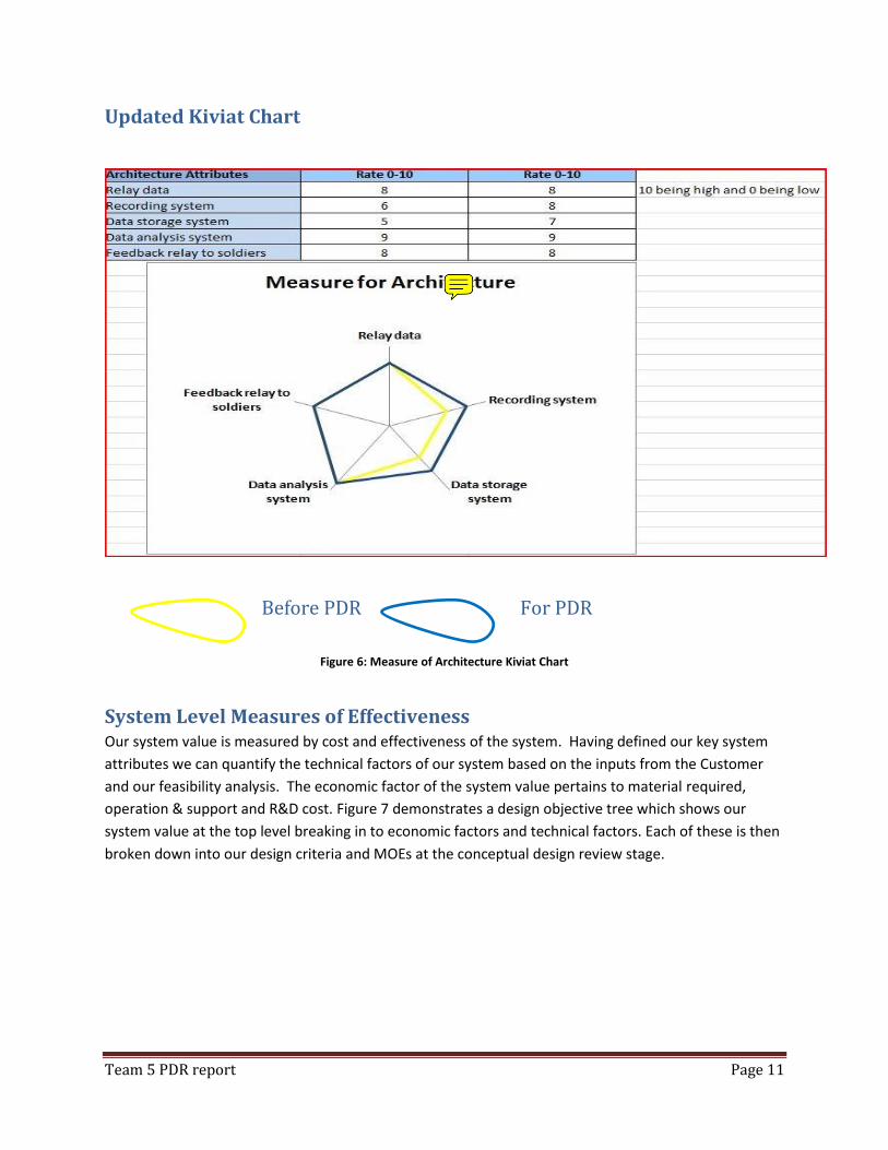
Updated Kiviat Chart
Before PDR For PDR
Figure 6: Measure of Architecture Kiviat Chart
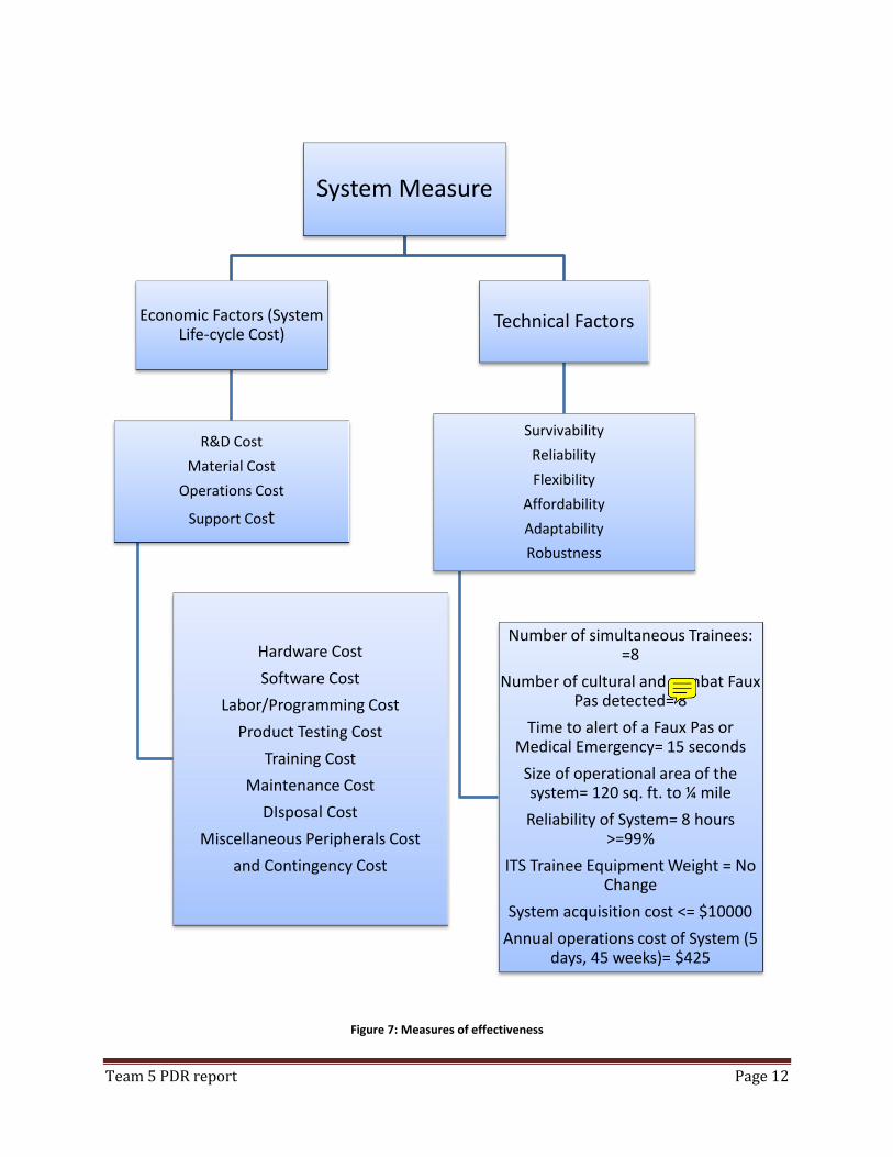
System Level Measures of Effectiveness Our system value is measured by cost and effectiveness of the system. Having defined our key system
attributes we can quantify the technical factors of our system based on the inputs from the Customer
and our feasibility analysis. The economic factor of the system value pertains to material required,
operation & support and R&D cost. Figure 7 demonstrates a design objective tree which shows our
system value at the top level breaking in to economic factors and technical factors. Each of these is then
broken down into our design criteria and MOEs at the conceptual design review stage.
Team 5 PDR report Page 12
Figure 7: Measures of effectiveness
System Measure
Economic Factors (System Life-cycle Cost)
R&D Cost
Material Cost
Operations Cost
Support Cost
Hardware Cost
Software Cost
Labor/Programming Cost
Product Testing Cost
Training Cost
Maintenance Cost
DIsposal Cost
Miscellaneous Peripherals Cost
and Contingency Cost
Technical Factors
Survivability
Reliability
Flexibility
Affordability
Adaptability
Robustness
Number of simultaneous Trainees: =8
Number of cultural and combat Faux Pas detected= 8
Time to alert of a Faux Pas or Medical Emergency= 15 seconds
Size of operational area of the system= 120 sq. ft. to ¼ mile
Reliability of System= 8 hours >=99%
ITS Trainee Equipment Weight = No Change
System acquisition cost <= $10000
Annual operations cost of System (5 days, 45 weeks)= $425
Team 5 PDR report Page 13
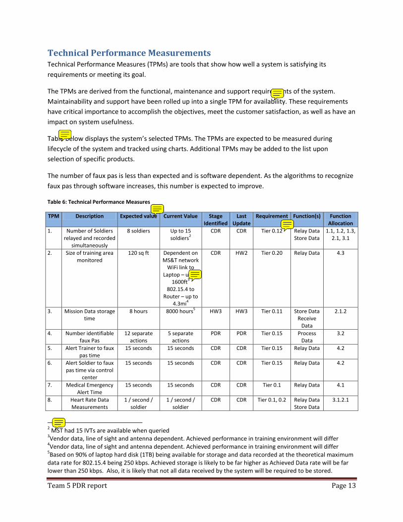
Technical Performance Measurements Technical Performance Measures (TPMs) are tools that show how well a system is satisfying its
requirements or meeting its goal.
The TPMs are derived from the functional, maintenance and support requirements of the system.
Maintainability and support have been rolled up into a single TPM for availability. These requirements
have critical importance to accomplish the objectives, meet the customer satisfaction, as well as have an
impact on system usefulness.
Table below displays the system’s selected TPMs. The TPMs are expected to be measured during
lifecycle of the system and tracked using charts. Additional TPMs may be added to the list upon
selection of specific products.
The number of faux pas is less than expected and is software dependent. As the algorithms to recognize
faux pas through software increases, this number is expected to improve.
Table 6: Technical Performance Measures
TPM Description Expected value Current Value Stage Identified
Last Update
Requirement Function(s) Function Allocation
1. Number of Soldiers relayed and recorded
simultaneously
8 soldiers Up to 15 soldiers
2
CDR CDR Tier 0.12 Relay Data Store Data
1.1, 1.2, 1.3, 2.1, 3.1
2. Size of training area monitored
120 sq ft Dependent on MS&T network
WiFi link to Laptop – up to
1600ft3
802.15.4 to Router – up to
4.3mi4
CDR HW2 Tier 0.20 Relay Data 4.3
3. Mission Data storage time
8 hours 8000 hours5 HW3 HW3 Tier 0.11
Store Data
Receive Data
2.1.2
4. Number identifiable faux Pas
12 separate actions
5 separate actions
PDR PDR Tier 0.15 Process Data
3.2
5. Alert Trainer to faux pas time
15 seconds 15 seconds CDR CDR Tier 0.15 Relay Data 4.2
6. Alert Soldier to faux pas time via control
center
15 seconds 15 seconds CDR CDR Tier 0.15 Relay Data 4.2
7. Medical Emergency Alert Time
15 seconds 15 seconds CDR CDR Tier 0.1 Relay Data 4.1
8. Heart Rate Data Measurements
1 / second / soldier
1 / second / soldier
CDR CDR Tier 0.1, 0.2 Relay Data Store Data
3.1.2.1
2 MST had 15 IVTs are available when queried
3Vendor data, line of sight and antenna dependent. Achieved performance in training environment will differ
4Vendor data, line of sight and antenna dependent. Achieved performance in training environment will differ
5Based on 90% of laptop hard disk (1TB) being available for storage and data recorded at the theoretical maximum
data rate for 802.15.4 being 250 kbps. Achieved storage is likely to be far higher as Achieved Data rate will be far lower than 250 kbps. Also, it is likely that not all data received by the system will be required to be stored.
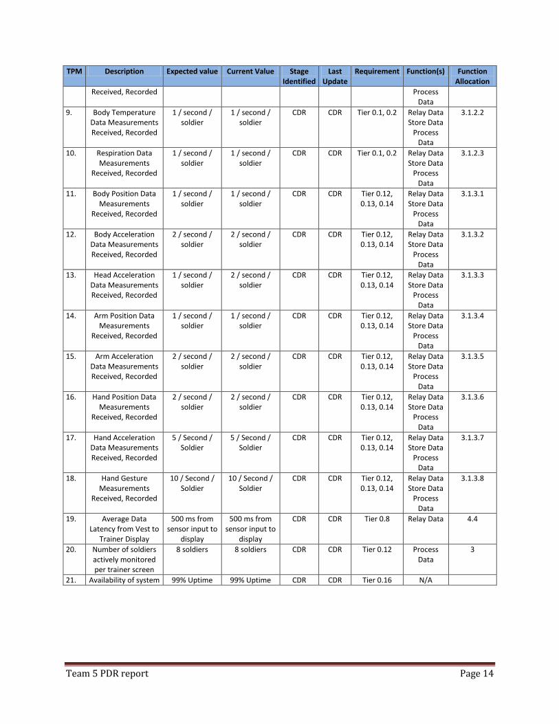
Team 5 PDR report Page 14
TPM Description Expected value Current Value Stage Identified
Last Update
Requirement Function(s) Function Allocation
Received, Recorded Process Data
9. Body Temperature Data Measurements Received, Recorded
1 / second / soldier
1 / second / soldier
CDR CDR Tier 0.1, 0.2 Relay Data Store Data
Process Data
3.1.2.2
10. Respiration Data Measurements
Received, Recorded
1 / second / soldier
1 / second / soldier
CDR CDR Tier 0.1, 0.2 Relay Data Store Data
Process Data
3.1.2.3
11. Body Position Data Measurements
Received, Recorded
1 / second / soldier
1 / second / soldier
CDR CDR Tier 0.12, 0.13, 0.14
Relay Data Store Data
Process Data
3.1.3.1
12. Body Acceleration Data Measurements Received, Recorded
2 / second / soldier
2 / second / soldier
CDR CDR Tier 0.12, 0.13, 0.14
Relay Data Store Data
Process Data
3.1.3.2
13. Head Acceleration Data Measurements Received, Recorded
1 / second / soldier
2 / second / soldier
CDR CDR Tier 0.12, 0.13, 0.14
Relay Data Store Data
Process Data
3.1.3.3
14. Arm Position Data Measurements
Received, Recorded
1 / second / soldier
1 / second / soldier
CDR CDR Tier 0.12, 0.13, 0.14
Relay Data Store Data
Process Data
3.1.3.4
15. Arm Acceleration Data Measurements Received, Recorded
2 / second / soldier
2 / second / soldier
CDR CDR Tier 0.12, 0.13, 0.14
Relay Data Store Data
Process Data
3.1.3.5
16. Hand Position Data Measurements
Received, Recorded
2 / second / soldier
2 / second / soldier
CDR CDR Tier 0.12, 0.13, 0.14
Relay Data Store Data
Process Data
3.1.3.6
17. Hand Acceleration Data Measurements Received, Recorded
5 / Second / Soldier
5 / Second / Soldier
CDR CDR Tier 0.12, 0.13, 0.14
Relay Data Store Data
Process Data
3.1.3.7
18. Hand Gesture Measurements
Received, Recorded
10 / Second / Soldier
10 / Second / Soldier
CDR CDR Tier 0.12, 0.13, 0.14
Relay Data Store Data
Process Data
3.1.3.8
19. Average Data Latency from Vest to
Trainer Display
500 ms from sensor input to
display
500 ms from sensor input to
display
CDR CDR Tier 0.8 Relay Data 4.4
20. Number of soldiers actively monitored per trainer screen
8 soldiers 8 soldiers CDR CDR Tier 0.12 Process Data
3
21. Availability of system 99% Uptime 99% Uptime CDR CDR Tier 0.16 N/A
Team 5 PDR report Page 15
Functional Analysis and Decomposition A functional decomposition was generated based satisfying Tier 0 requirements. From these
requirements, it was identified that the system must: receive data from the ITV, process and prioritize
the received data, store the data, relay the data to the trainer, receive inputs from the trainer and
activate the ITV to alert soldiers of identified events.
The functional breakdown shown in Figure 8 below gives the design as presented to and approved by
the customer. This design depicts a system where data is first processed and prioritized prior to
relaying to the trainer and storing to the recording device.
Receive Data The six functions depicted in Figure 8 represent a top level decomposition of the system. The initial first
level function, 1: Receive Data, is the entry point into the system. This is where data is received by the
Meshlium router from the soldier’s ITV. The Receive Data function is comprised of three second level
functions, 1.1 Receive Data from ITV, 1.2 Utilize existing ITV equipment, and 1.3 Utilize existing ITV data
formats. These functions cover the requirements for the system to utilize an 802.15.4 interface through
the Missouri MOTE and receive data from up to eight soldiers simultaneously. Figure 9 below details the
decomposition of this function.
1: Receive Data
1.1: Receive Data
from ITV
1.2: Utilize existing ITV equipment
1.3: Utilize existing ITV data
formats
1.2.1: Interface with Missouri
MOTE
1.2.1.1: support 802.15.4 interface
1.0
Receive Data from ITV
3.0
Store Data
4.0
Relay Data
2.0
Process Data
5.0
Receive Data from
Trainer
6.0
Alert Soldier
Figure 9: Receive Data Function
Figure 8: PDR Functional Decomposition
Team 5 PDR report Page 16
1.0 Receive Data
T1:1.1 The system shall support multiple soldiers simultaneously
T1:1.2 The receiving hardware shall have 99% uptime
1.1 Receive Data from ITV
T2:1.1.1 The system shall support existing Missouri MOTE interfaces
1.2 Utilize existing ITV equipment
T2:1.2.1 The system shall interface with the existing ITV equipment
1.3 Utilize existing ITV data formats
T2:1.3.1 The system shall support existing ITV data formats
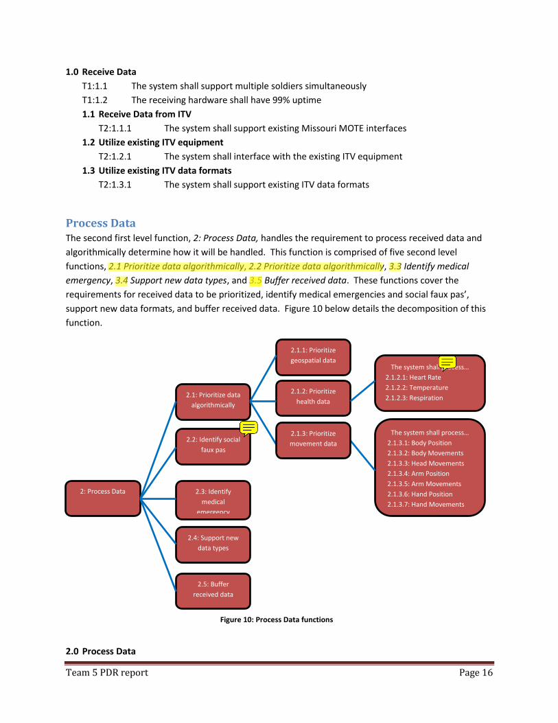
Process Data The second first level function, 2: Process Data, handles the requirement to process received data and
algorithmically determine how it will be handled. This function is comprised of five second level
functions, 2.1 Prioritize data algorithmically, 2.2 Prioritize data algorithmically, 3.3 Identify medical
emergency, 3.4 Support new data types, and 3.5 Buffer received data. These functions cover the
requirements for received data to be prioritized, identify medical emergencies and social faux pas’,
support new data formats, and buffer received data. Figure 10 below details the decomposition of this
function.
2.0 Process Data
2: Process Data
2.1: Prioritize data
algorithmically
2.2: Identify social
faux pas
2.1.1: Prioritize
geospatial data
2.1.2: Prioritize
health data
The system shall process… 2.1.3.1: Body Position 2.1.3.2: Body Movements 2.1.3.3: Head Movements 2.1.3.4: Arm Position 2.1.3.5: Arm Movements 2.1.3.6: Hand Position 2.1.3.7: Hand Movements
2.3: Identify
medical
emergency
2.4: Support new
data types
2.5: Buffer
received data
2.1.3: Prioritize
movement data
The system shall process… 2.1.2.1: Heart Rate 2.1.2.2: Temperature 2.1.2.3: Respiration
Figure 10: Process Data functions
Team 5 PDR report Page 17
T1:1.1 The system shall actively monitor 8 soldiers on the trainer screen
T1:1.2 The system shall be able to process streamed data
Prioritize data algorithmically
T2:3.1.1 The system shall prioritize geospatial data
T2:3.1.2 The system shall prioritize health data
T2:3.1.3 The system shall prioritize movement data
2.1 Identify social faux pas
T2:3.2.1 The system shall identify a social faux pas within 15 seconds
T2:3.2.2 The system shall identify at minimum 12 separate faux pas’
2.2 Identify medical emergency
T2:3.3.1 The system shall identify a medical emergency within 15 seconds
2.3 Support new data types
T2:3.4.1 The system shall be easily modifiable to support new data types
T2:3.4.2 The system shall be manageable by a single person
2.4 Buffer Received Data
T2:3.5.1 The system shall treat all received data as unclassified
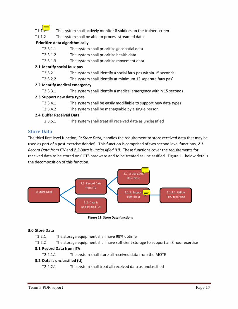
Store Data The third first level function, 3: Store Data, handles the requirement to store received data that may be
used as part of a post-exercise debrief. This function is comprised of two second level functions, 2.1
Record Data from ITV and 2.2 Data is unclassified (U). These functions cover the requirements for
received data to be stored on COTS hardware and to be treated as unclassified. Figure 11 below details
the decomposition of this function.
3.0 Store Data
T1:2.1 The storage equipment shall have 99% uptime
T1:2.2 The storage equipment shall have sufficient storage to support an 8 hour exercise
3.1 Record Data from ITV
T2:2.1.1 The system shall store all received data from the MOTE
3.2 Data is unclassified (U)
T2:2.2.1 The system shall treat all received data as unclassified
3: Store Data
3.1: Record Data
from ITV
3.2: Data is
unclassified (U)
3.1.1: Use COTS
Hard Drive
3.1.2: Support
eight hour
exercise
3.1.2.1: Utilize
FIFO recording
Figure 11: Store Data functions
Team 5 PDR report Page 18
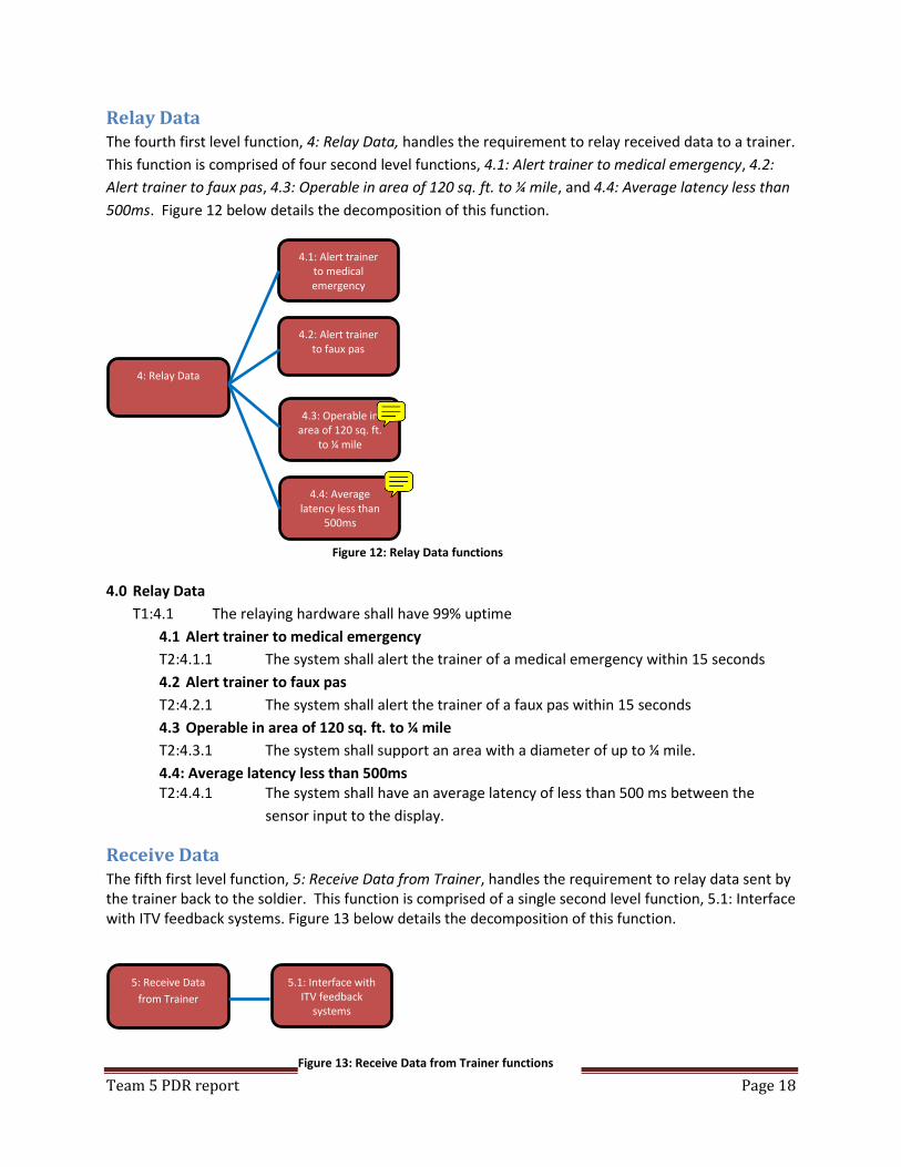
Relay Data The fourth first level function, 4: Relay Data, handles the requirement to relay received data to a trainer.
This function is comprised of four second level functions, 4.1: Alert trainer to medical emergency, 4.2:
Alert trainer to faux pas, 4.3: Operable in area of 120 sq. ft. to ¼ mile, and 4.4: Average latency less than
500ms. Figure 12 below details the decomposition of this function.
4.0 Relay Data
T1:4.1 The relaying hardware shall have 99% uptime
4.1 Alert trainer to medical emergency
T2:4.1.1 The system shall alert the trainer of a medical emergency within 15 seconds
4.2 Alert trainer to faux pas
T2:4.2.1 The system shall alert the trainer of a faux pas within 15 seconds
4.3 Operable in area of 120 sq. ft. to ¼ mile
T2:4.3.1 The system shall support an area with a diameter of up to ¼ mile.
4.4: Average latency less than 500ms T2:4.4.1 The system shall have an average latency of less than 500 ms between the
sensor input to the display.
Receive Data The fifth first level function, 5: Receive Data from Trainer, handles the requirement to relay data sent by the trainer back to the soldier. This function is comprised of a single second level function, 5.1: Interface with ITV feedback systems. Figure 13 below details the decomposition of this function.
4: Relay Data
4.1: Alert trainer to medical emergency
4.2: Alert trainer to faux pas
4.3: Operable in area of 120 sq. ft.
to ¼ mile
4.4: Average latency less than
500ms
5: Receive Data
from Trainer
5.1: Interface with ITV feedback
systems
Figure 12: Relay Data functions
Figure 13: Receive Data from Trainer functions
Team 5 PDR report Page 19
5.0 Receive Data from Trainer
T1:5.1 The receiving hardware shall have 99% uptime
5.1 Interface with ITV feedback systems
T2:5.1.1 The system shall interface with the existing ITV feedback systems
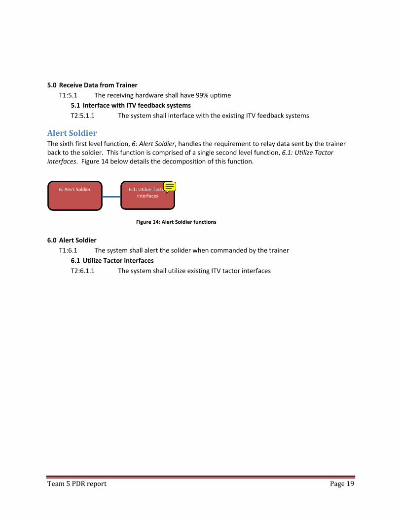
Alert Soldier The sixth first level function, 6: Alert Soldier, handles the requirement to relay data sent by the trainer back to the soldier. This function is comprised of a single second level function, 6.1: Utilize Tactor interfaces. Figure 14 below details the decomposition of this function.
6.0 Alert Soldier
T1:6.1 The system shall alert the solider when commanded by the trainer
6.1 Utilize Tactor interfaces
T2:6.1.1 The system shall utilize existing ITV tactor interfaces
6: Alert Soldier
6.1: Utilize Tactor interfaces
Figure 14: Alert Soldier functions
Team 5 PDR report Page 20
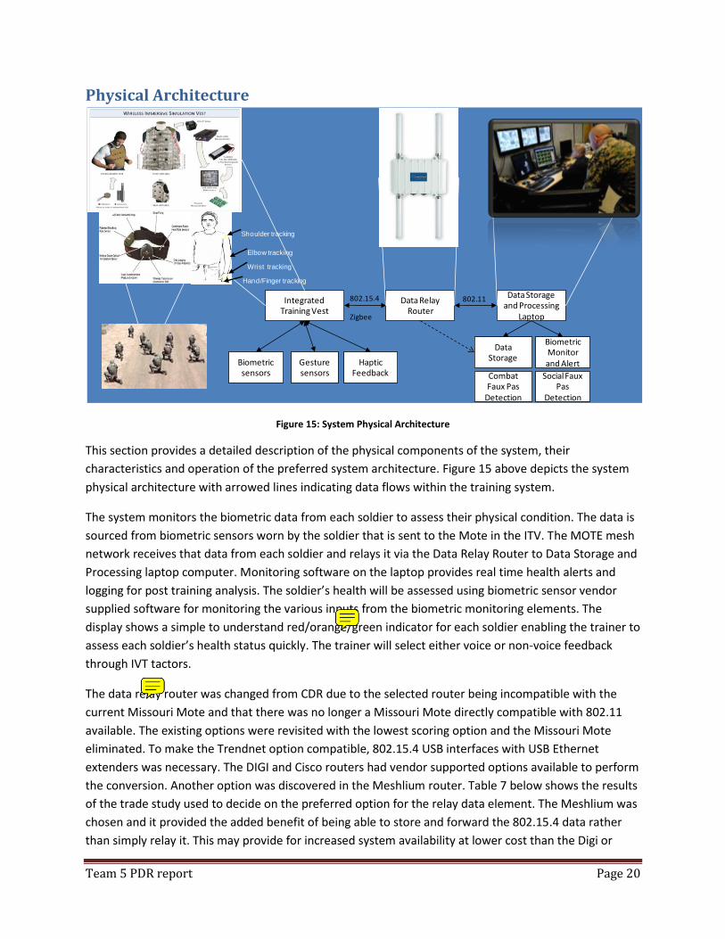
Physical Architecture
Figure 15: System Physical Architecture
This section provides a detailed description of the physical components of the system, their
characteristics and operation of the preferred system architecture. Figure 15 above depicts the system
physical architecture with arrowed lines indicating data flows within the training system.
The system monitors the biometric data from each soldier to assess their physical condition. The data is
sourced from biometric sensors worn by the soldier that is sent to the Mote in the ITV. The MOTE mesh
network receives that data from each soldier and relays it via the Data Relay Router to Data Storage and
Processing laptop computer. Monitoring software on the laptop provides real time health alerts and
logging for post training analysis. The soldier’s health will be assessed using biometric sensor vendor
supplied software for monitoring the various inputs from the biometric monitoring elements. The
display shows a simple to understand red/orange/green indicator for each soldier enabling the trainer to
assess each soldier’s health status quickly. The trainer will select either voice or non-voice feedback
through IVT tactors.
The data relay router was changed from CDR due to the selected router being incompatible with the
current Missouri Mote and that there was no longer a Missouri Mote directly compatible with 802.11
available. The existing options were revisited with the lowest scoring option and the Missouri Mote
eliminated. To make the Trendnet option compatible, 802.15.4 USB interfaces with USB Ethernet
extenders was necessary. The DIGI and Cisco routers had vendor supported options available to perform
the conversion. Another option was discovered in the Meshlium router. Table 7 below shows the results
of the trade study used to decide on the preferred option for the relay data element. The Meshlium was
chosen and it provided the added benefit of being able to store and forward the 802.15.4 data rather
than simply relay it. This may provide for increased system availability at lower cost than the Digi or
Integrated Training Vest
Biometric sensors
Gesture sensors
Data Storage and Processing
Laptop
Data Relay Router
802.11802.15.4
Zigbee
Combat Faux Pas
Detection
Social Faux Pas
Detection
Data Storage
Biometric Monitor and AlertHaptic
Feedback
Wrist tracking
Elbow tracking
Shoulder tracking
Hand/Finger tracking
Team 5 PDR report Page 21
Cisco options, and lower complexity than the modified Trendnet option. The modified Trendnet option
is also likely to have higher through life cost due to the increased complexity.
Table 7: Replacement Relay Data Element
Criteria Weighting Altern
ate
1:
Cis
co 1
552S
Weig
hte
d S
core
Altern
ate
2:
Tre
ndnet
+ U
SB
Weig
hte
d S
core
Altern
ate
3:
National in
str
um
ents
Weig
hte
d S
core
Altern
ate
4:
Meshliu
m
Weig
hte
d S
core
Cost 30 1 0.3 3 0.9 1 0.3 3 0.9
Power Consumption 15 9 1.35 3 0.45 9 1.35 9 1.35
Range 15 9 1.35 3 0.45 3 0.45 9 1.35
Complexity 20 9 1.8 3 0.6 9 1.8 9 1.8
Data Transfer Rate 20 9 1.8 3 0.6 9 1.8 9 1.8
6.60 3.00 5.70 7.20
The system monitors the soldier location to assess a combat faux pas. The soldier’s location data is
sourced from the Missouri Mote network and will be compared to the location of other soldiers and
actors in the environment. Combat faux pas criteria will be used to determine if the current soldier
location is in breach of the combat rules. The system will display shows a simple to understand
red/orange/green indicator for each soldier in a representation of the training environment to enable
the trainer to quickly assess combat faux pas. Social faux pas criteria will be used to determine if the
soldier’s current movement relative to an actor is in breach of social rules. The system will display a
simple to understand indicator for each soldier in a representation of the training environment to
enable the trainer to quickly assess a social faux pas. The trainer will select either voice or non-voice
feedback through IVT tactors for combat and social faux pas. Voice feedback will be via soldier radios
which are outside of the scope of this system.
The system monitors the soldier’s hand gestures to assess social faux pas. Data from the hand gestures
monitoring element is sent to the Mote in the ITV. The MOTE mesh network receives that data from
each soldier and relays it via the Data Relay Router to Data Storage and Processing laptop computer.
Social faux pas criteria will be used to determine if the soldier’s current movement relative to an actor is
in breach of social rules. The system will display a simple to understand indicator for each soldier in a
representation of the training environment to enable the trainer to quickly assess a social faux pas. The
trainer will select either voice or non-voice feedback through IVT tactors for social faux pas. The voice
radio network that is used for voice feedback in alerting a soldier is external to this system and is not
shown.
The system recognizes which set of equipment is allocated to a soldier. This equipment allocated to a
soldier includes the IVT, the biometric harness, and the gesture monitoring equipment. The system will
Team 5 PDR report Page 22
record biometric data based on the recording capabilities within the COTS biometric software. The
custom analysis software will track the IVT allocated to the soldier and provide for updating the
information during a training exercise. Data recording through the custom software will include any
unique equipment identifiers to aid in offline analysis of any faults.
The dotted line shown in Figure 15 from data relay router to data storage indicates that the data relay
router has the ability to store and forward information contained in the 802.15.4/Zigbee frames. This
flexibility allows for the mission to continue should the laptop be temporarily inaccessible with no data
loss. Data stored is stored to a local hard drive on the laptop. An external hard drive or flash memory
device can be used. A 1TB external hard drive has been included in the costing of the system but is not
necessary for the system to operate.
Functional to Physical Mapping This section shows the relationship between the functions obtained in the functional decomposition and
the elements in the physical architecture. For the purposes of this section, software components are
treated as part of the physical architecture. Software architectural analysis has not been undertaken.
Error! Reference source not found. show the relationship between the high level functions and the
physical architecture elements.
Team 5 PDR report Page 23
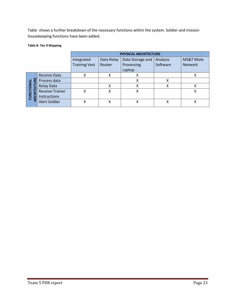
Table shows a further breakdown of the necessary functions within the system. Soldier and mission
housekeeping functions have been added.
Table 8: Tier 0 Mapping
PHYSICAL ARCHITECTURE
Integrated Training Vest
Data Relay Router
Data Storage and Processing Laptop
Analysis Software
MS&T Mote Network
FUN
CTI
ON
AL
AR
CH
ITEC
TUR
E Receive Data X X X X
Process data X X
Relay Data X X X X
Receive Trainer Instructions
X X X X
Alert Soldier X X X X X
Team 5 PDR report Page 24
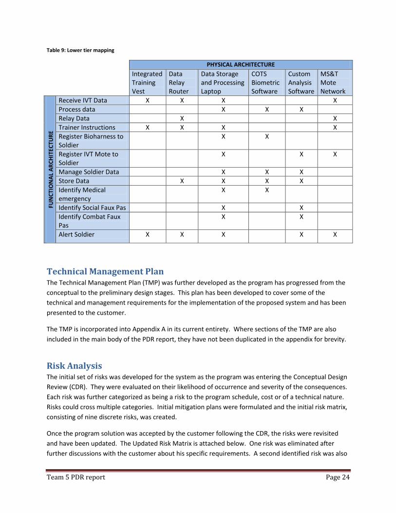
Table 9: Lower tier mapping
PHYSICAL ARCHITECTURE
Integrated Training Vest
Data Relay Router
Data Storage and Processing Laptop
COTS Biometric Software
Custom Analysis Software
MS&T Mote Network
FUN
CTI
ON
AL
AR
CH
ITEC
TUR
E
Receive IVT Data X X X X
Process data X X X
Relay Data X X
Trainer Instructions X X X X
Register Bioharness to Soldier
X X
Register IVT Mote to Soldier
X X X
Manage Soldier Data X X X
Store Data X X X X
Identify Medical emergency
X X
Identify Social Faux Pas X X
Identify Combat Faux Pas
X X
Alert Soldier X X X X X
Technical Management Plan The Technical Management Plan (TMP) was further developed as the program has progressed from the
conceptual to the preliminary design stages. This plan has been developed to cover some of the
technical and management requirements for the implementation of the proposed system and has been
presented to the customer.
The TMP is incorporated into Appendix A in its current entirety. Where sections of the TMP are also
included in the main body of the PDR report, they have not been duplicated in the appendix for brevity.
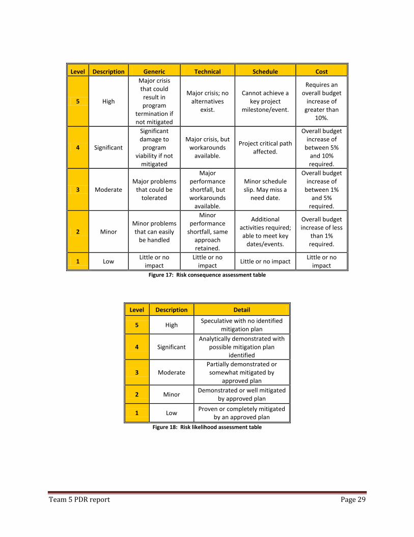
Risk Analysis The initial set of risks was developed for the system as the program was entering the Conceptual Design
Review (CDR). They were evaluated on their likelihood of occurrence and severity of the consequences.
Each risk was further categorized as being a risk to the program schedule, cost or of a technical nature.
Risks could cross multiple categories. Initial mitigation plans were formulated and the initial risk matrix,
consisting of nine discrete risks, was created.
Once the program solution was accepted by the customer following the CDR, the risks were revisited
and have been updated. The Updated Risk Matrix is attached below. One risk was eliminated after
further discussions with the customer about his specific requirements. A second identified risk was also

Team 5 PDR report Page 25
eliminated after confirming with the Missouri University of Science and Technology (MST) that software
licenses were available for the Team’s use. These two risks remain in the Updated Risk Matrix for
traceability, but have been denoted as eliminated.
Three additional risks have been identified as the program approaches the Preliminary Design Review
(PDR) stage. These are incorporated at the end of the Updated Risk Matrix. Contingency plans have
been developed for two of these risks. The third ‘new’ risk is considered to be of low enough likelihood
that the risk is acknowledged and accepted without developed mitigation. This risk involves the delivery
of third party code with defects present. It is unlikely that this would happen, but if it did the code
would have to be corrected to eliminate the consequences of this risk to the system.
The remaining seven (7) initial risks have been reevaluated and further contingency plans and mitigation
has been put in place for three of these risks. This mitigation has resulted in the risk levels being
reduced.
All high level risks have now been eliminated. All of the remaining moderate risk level items involve the
integration of all of the systems together. These risks vary from hardware potential hardware
compatibility problems, for example the Missouri Mote and the wireless routers not communicating, to
integration of the various legacy systems and the code that will interpret all the data. However, all risk
levels are now considered to be at a manageable level and early field testing will eliminate or allow the
team to develop further contingency plans as the program moves forward.
The risks identified in the system continue to be fluid and mitigation efforts continue to reduce overall
project risk. Risk will be reevaluated at each stage of the program and changes will continue to be
denoted in updated matrices with all changes notated.
Team 5 PDR report Page 26
Updated Risk Matrix
Lik
elih
oo
d
Co
nseq
uen
ce
Category
Ite
m
Ris
k D
esc
rip
tio
n
Tec
hn
ical
Sch
edu
le
Co
st
CD
R R
isk
Leve
l
Mo
dif
ied
Ris
k Le
vel
Mit
igat
ion
Act
ion
s
Ad
dit
ion
al
Co
nti
nge
ncy
/
Mit
igat
ion
Ide
nti
fie
d
1
Team member unable to participate (illness, localized adverse events, ...)
2 4
X
Mo
der
ate
Low
Other team member(s) will work actions assigned to unavailable team member.
Contingency plans developed and team members have sufficient inter-disciplinary skills to complete all tasks.
2 Mentors unavailable for review
1 4 X Lo
w
Low
Two mentors available for comments, MST to provide alternate if either unavailable for lengthy period.
3 Mote and router don't integrate
2 5 X
Mo
der
ate
Mo
der
ate/
Low
Establish contact with Mote team to work through alternate solutions. Prototype as early as possible.
Initial CDR level router abandoned. Contact has been made with alternate supplier who has confirmed compatibility with MOTE system.
4 Team communications issues
1 4
X Lo
w
Low
Alternate communications channels have been distributed.
5
Availability and effectiveness of development tools.
1 3
X X
Low
Ris
k El
imin
ated
MST holds several licenses for development software chosen. It is available in several computer laboratories.
MST has confirmed that the team may use MST licenses
Team 5 PDR report Page 27
Lik
elih
oo
d
Co
nseq
uen
ce
Category
Ite
m
Ris
k D
esc
rip
tio
n
Tec
hn
ical
Sch
edu
le
Co
st
CD
R R
isk
Leve
l
Mo
dif
ied
Ris
k Le
vel
Mit
igat
ion
Act
ion
s
Ad
dit
ion
al
Co
nti
nge
ncy
/
Mit
igat
ion
Ide
nti
fie
d
6 Costs of development tools.
3 5
X
Hig
h
Low
Each additional development licenses represents >10% of the overall budget.
MST has confirmed that additional development licenses may be used as a part of this project.
7
Data rate from multiple motes exceeds available bandwidth
3 5 X H
igh
Mo
der
ate
Possible addition of Multiple Meshlium components will alleviate any bandwidth issues
Field Testing to determine bandwidth shall be tested early in detailed design.
8
Use of existing communications and power networks
3 4 X
Mo
der
ate
Mo
der
ate
Installation site survey required to locate networks. Use batteries and wireless communications as alternate where suitable.
9 End user security requirements
2 4 X
X
Mo
der
ate
Ris
k El
imin
ate
d
Solution uses commercial grade encryption. If customer requires higher grade, additional design effort will be required.
Customer has confirmed that this program is Unclassified level security
Team 5 PDR report Page 28
Lik
elih
oo
d
Co
nseq
uen
ce
Category
Ite
m
Ris
k D
esc
rip
tio
n
Tec
hn
ical
Sch
edu
le
Co
st
CD
R R
isk
Leve
l
Mo
dif
ied
Ris
k Le
vel
Mit
igat
ion
Act
ion
s
Ad
dit
ion
al
Co
nti
nge
ncy
/
Mit
igat
ion
Ide
nti
fie
d
10
Virtual Cultural Monitoring System is not available for integration
3 4 X N/A
Mo
der
ate
Availability of VCMS must be confirmed through appropriate contacts. If system not available, similar system will be developed.
11
System Code Complexity is higher than anticipated to integrate all systems
2 4 X X X N/A
Mo
der
ate
Preliminary code development will be developed earlier in the PDR process
12
System Code from third party is delivered with defects
1 4 X X X N/A
Low
Acceptable risk involved in item
Figure 16: Risks
Team 5 PDR report Page 29
Level Description Generic Technical Schedule Cost
5 High
Major crisis that could result in program
termination if not mitigated
Major crisis; no alternatives
exist.
Cannot achieve a key project
milestone/event.
Requires an overall budget
increase of greater than
10%.
4 Significant
Significant damage to program
viability if not mitigated
Major crisis, but workarounds
available.
Project critical path affected.
Overall budget increase of
between 5% and 10% required.
3 Moderate Major problems
that could be tolerated
Major performance shortfall, but workarounds
available.
Minor schedule slip. May miss a
need date.
Overall budget increase of
between 1% and 5%
required.
2 Minor Minor problems that can easily
be handled
Minor performance
shortfall, same approach retained.
Additional activities required; able to meet key
dates/events.
Overall budget increase of less
than 1% required.
1 Low Little or no
impact Little or no
impact Little or no impact
Little or no impact
Figure 17: Risk consequence assessment table
Level Description Detail
5 High Speculative with no identified
mitigation plan
4 Significant Analytically demonstrated with
possible mitigation plan identified
3 Moderate Partially demonstrated or somewhat mitigated by
approved plan
2 Minor Demonstrated or well mitigated
by approved plan
1 Low Proven or completely mitigated
by an approved plan
Figure 18: Risk likelihood assessment table
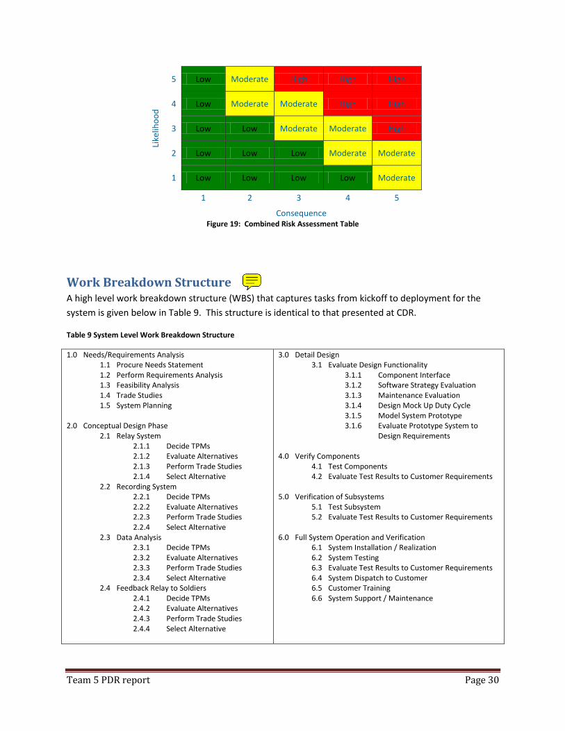
Team 5 PDR report Page 30
Like
liho
od
5 Low Moderate High High High
4 Low Moderate Moderate High High
3 Low Low Moderate Moderate High
2 Low Low Low Moderate Moderate
1 Low Low Low Low Moderate
1 2 3 4 5
Consequence Figure 19: Combined Risk Assessment Table
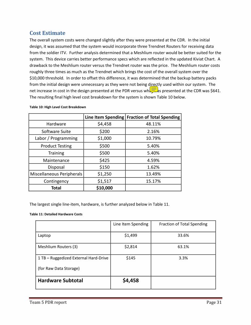
Work Breakdown Structure A high level work breakdown structure (WBS) that captures tasks from kickoff to deployment for the
system is given below in Table 9. This structure is identical to that presented at CDR.
Table 9 System Level Work Breakdown Structure
1.0 Needs/Requirements Analysis 1.1 Procure Needs Statement 1.2 Perform Requirements Analysis 1.3 Feasibility Analysis 1.4 Trade Studies 1.5 System Planning
2.0 Conceptual Design Phase
2.1 Relay System 2.1.1 Decide TPMs 2.1.2 Evaluate Alternatives 2.1.3 Perform Trade Studies 2.1.4 Select Alternative
2.2 Recording System 2.2.1 Decide TPMs 2.2.2 Evaluate Alternatives 2.2.3 Perform Trade Studies 2.2.4 Select Alternative
2.3 Data Analysis 2.3.1 Decide TPMs 2.3.2 Evaluate Alternatives 2.3.3 Perform Trade Studies 2.3.4 Select Alternative
2.4 Feedback Relay to Soldiers 2.4.1 Decide TPMs 2.4.2 Evaluate Alternatives 2.4.3 Perform Trade Studies 2.4.4 Select Alternative
3.0 Detail Design 3.1 Evaluate Design Functionality
3.1.1 Component Interface 3.1.2 Software Strategy Evaluation 3.1.3 Maintenance Evaluation 3.1.4 Design Mock Up Duty Cycle 3.1.5 Model System Prototype 3.1.6 Evaluate Prototype System to
Design Requirements
4.0 Verify Components 4.1 Test Components 4.2 Evaluate Test Results to Customer Requirements
5.0 Verification of Subsystems 5.1 Test Subsystem 5.2 Evaluate Test Results to Customer Requirements
6.0 Full System Operation and Verification 6.1 System Installation / Realization 6.2 System Testing 6.3 Evaluate Test Results to Customer Requirements 6.4 System Dispatch to Customer 6.5 Customer Training 6.6 System Support / Maintenance
Team 5 PDR report Page 31
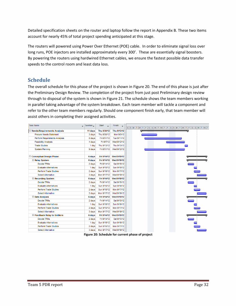
Cost Estimate The overall system costs were changed slightly after they were presented at the CDR. In the initial
design, it was assumed that the system would incorporate three Trendnet Routers for receiving data
from the soldier ITV. Further analysis determined that a Meshlium router would be better suited for the
system. This device carries better performance specs which are reflected in the updated Kiviat Chart. A
drawback to the Meshlium router versus the Trendnet router was the price. The Meshlium router costs
roughly three times as much as the Trendnet which brings the cost of the overall system over the
$10,000 threshold. In order to offset this difference, it was determined that the backup battery packs
from the initial design were unnecessary as they were not being directly used within our system. The
net increase in cost in the design presented at the PDR versus what was presented at the CDR was $641.
The resulting final high level cost breakdown for the system is shown Table 10 below.
Table 10: High Level Cost Breakdown
Line Item Spending Fraction of Total Spending
Hardware $4,458 48.11%
Software Suite $200 2.16%
Labor / Programming $1,000 10.79%
Product Testing $500 5.40%
Training $500 5.40%
Maintenance $425 4.59%
Disposal $150 1.62%
Miscellaneous Peripherals $1,250 13.49%
Contingency $1,517 15.17%
Total $10,000
The largest single line-item, hardware, is further analyzed below in Table 11.
Table 11: Detailed Hardware Costs
Line Item Spending Fraction of Total Spending
Laptop $1,499 33.6%
Meshlium Routers (3) $2,814 63.1%
1 TB – Ruggedized External Hard-Drive
(for Raw Data Storage)
$145 3.3%
Hardware Subtotal $4,458
Team 5 PDR report Page 32
Detailed specification sheets on the router and laptop follow the report in Appendix B. These two items
account for nearly 45% of total project spending anticipated at this stage.
The routers will powered using Power Over Ethernet (POE) cable. In order to eliminate signal loss over
long runs, POE injectors are installed approximately every 300’. These are essentially signal boosters.
By powering the routers using hardwired Ethernet cables, we ensure the fastest possible data transfer
speeds to the control room and least data loss.
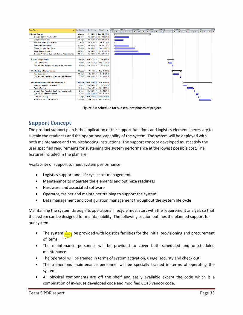
Schedule The overall schedule for this phase of the project is shown in Figure 20. The end of this phase is just after
the Preliminary Design Review. The completion of the project from just post Preliminary design review
through to disposal of the system is shown in Figure 21. The schedule shows the team members working
in parallel taking advantage of the system breakdown. Each team member will tackle a component and
refer to the other team members regularly. Should one component finish early, that team member will
assist others in completing their assigned activities.
Figure 20: Schedule for current phase of project
Team 5 PDR report Page 33
Figure 21: Schedule for subsequent phases of project
Support Concept The product support plan is the application of the support functions and logistics elements necessary to
sustain the readiness and the operational capability of the system. The system will be deployed with
both maintenance and troubleshooting instructions. The support concept developed must satisfy the
user specified requirements for sustaining the system performance at the lowest possible cost. The
features included in the plan are:
Availability of support to meet system performance
Logistics support and Life cycle cost management
Maintenance to integrate the elements and optimize readiness
Hardware and associated software
Operator, trainer and maintainer training to support the system
Data management and configuration management throughout the system life cycle
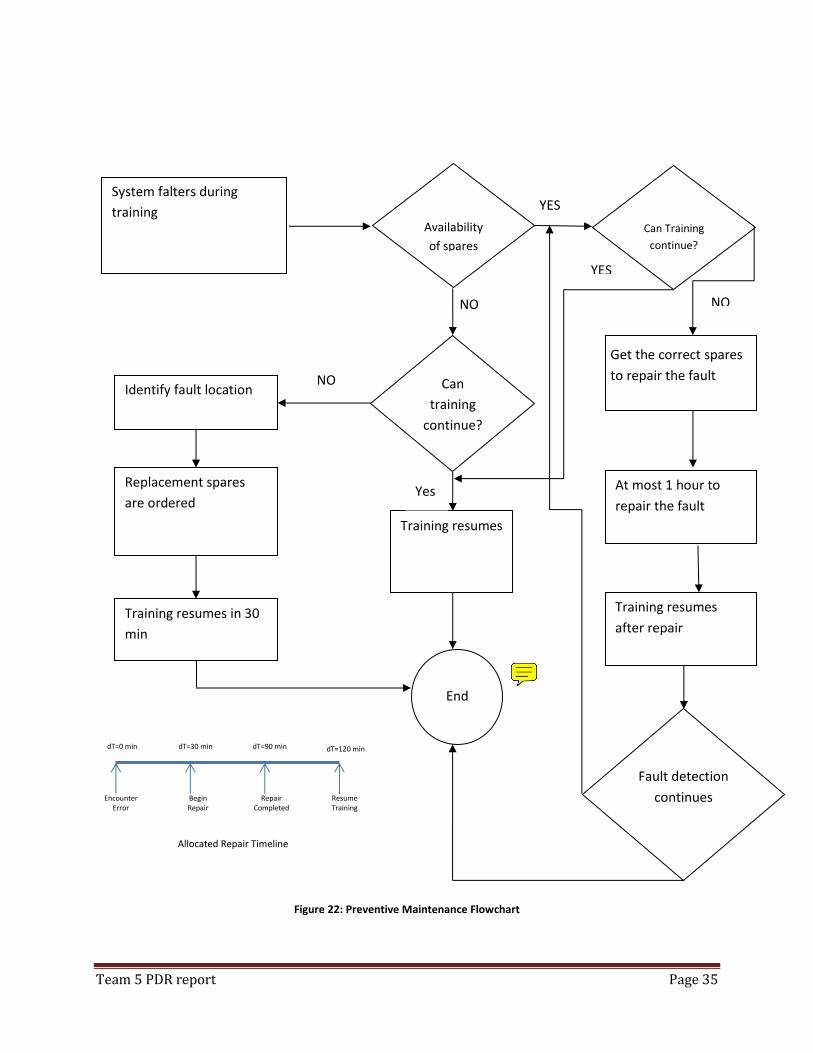
Maintaining the system through its operational lifecycle must start with the requirement analysis so that
the system can be designed for maintainability. The following section outlines the planned support for
our system:
The system shall be provided with logistics facilities for the initial provisioning and procurement
of items.
The maintenance personnel will be provided to cover both scheduled and unscheduled
maintenance.
The operator will be trained in terms of system activation, usage, security and check out.
The trainer and maintenance personnel will be specially trained in terms of operating the
system.
All physical components are off the shelf and easily available except the code which is a
combination of in-house developed code and modified COTS vendor code.

Team 5 PDR report Page 34
The system will be shipped with the following manuals: instructions, training, user, maintenance
and troubleshooting manuals.
Technical data including system design (system drawing, specifications), system modification,
logistics provisioning and procurement data, supplier data, interfacing, system operational and
maintenance data and other supporting databases will be documented.
The system shall be provided with additional spare parts only if identified and required during the
operational phase of the system as per the requirements.
Figure 22 provides the basic availability operations concept for our training system considering spares
also.
Team 5 PDR report Page 35
Figure 22: Preventive Maintenance Flowchart
Encounter Error
Begin
Repair Repair
Completed
Resume
Training
dT=0 min dT=30 min dT=90 min dT=120 min
Allocated Repair Timeline
System falters during
training
Get the correct spares
to repair the fault
At most 1 hour to
repair the fault
Training resumes
after repair
Training resumes
Availability
of spares
Can
training
continue?
End
YES
NO
Identify fault location
Replacement spares
are ordered
Training resumes in 30
min
Fault detection
continues
NO
Yes
Can Training
continue?
YES
NO

Team 5 PDR report Page 36
Training events will have enough systems in a “stand by” mode. In the event a system in training
becomes NMC (Non-mission capable) the additional system will be used. The supportability equation
will determine appropriate number of systems using anticipated failure rate. Major maintenance issues
will be shipped back to manufacturer for repairs under warranty.
The manufacturer will provide an easy to read and understand “User’s manual” to ensure all parties,
Soldiers and trainers know how to properly use the equipment. The manual will contain information on
regular use, simple maintenance procedures, list of components for accountability purposes and
troubleshooting guide at a minimum. The system will be fully repairable. All minor repairs will be able to
be made at the user level through use of the “User’s manual”
The customer will be responsible for initiating repairs. The manufacturer will be responsible for
supplying customer with necessary repair parts if repair is simple enough, or make repairs on significant
maintenance issues.

Team 5 PDR report Page 37
Program Management Best Practices (PMBP) Extremely important in these days of commercial investment to meet cost and schedule goals. These are
the PMBP that are used to ensure the success of this and all programs in this corporation use.
Have strong organizational structure
Our structure is based upon our core competencies that allow us to assign standard company resources
such as Engineering, Accounting, Management oversight and Systems Engineering to each program on
an as needed basis. This ensures that programs don’t have the added expense of a full time person
charging to the program when only part-time is needed. This allows us to utilize our staff more
efficiently while keeping costs down.
Manage to a set of requirements
Each project comes with its own set of requirements, and while we strive to keep costs down by reusing
existing designs, this is only done with the review of the existing technology to ensure it will properly
meet the customers requirement and with a customer review of our plan of how we will meet each
requirement and the method of validating and verifying that the requirement has been met.
Identify risks early and develop plans to mitigate or avoid
In each new requirement, there is an inherent risk that parts, products and services may fail to live up to
the expectations in the design. Prior to making a final decision on a plan for a project, we strive to have
alternate plans, methods or vendors to ensure that should an issue arise, we have things in place to
mitigate any foreseeable system failures.
Integrated Master Planning (IMP) and Scheduling (IMS)
Making use of IMPs and IMSs, allow us to keep track and manage each program efficiently by knowing
what our plan and schedule milestones are, and adjust staffing and or make use of our Engineers and
Tech Fellows to help solve issues before they become big problems.
Manage to the baseline budget & schedule, keep track of changes.
Our managers’ report weekly on the progress of each program that they are responsible for with the use
of our Earned Value Management (EVM) that tracks both out cost and schedule variances.
Plan for affordability- design for cost
Our Systems Engineering approach to allow us to review projects each step of the way to ensure we are
using the right parts and products needed to provide a robust product while keeping costs down by not
over-engineering the systems requirements.
Have frequent communication with the customer
Each step of the way, we review where we are and any problems or milestones that have been
achieved. Both the good and bad are communicated to the customer to ensure that things are dealt
with and adjustments can be made that will best suite both us and the customer.

Team 5 PDR report Page 38
Promote a culture of asking for help when needed
We believe that the only bad question is the one that is not asked. We encourage our senior discipline
employees to develop a mentoring relationship with those that are just starting out or those that are
learning new technologies to be used on developing new products or updating older designs to prolong
the usable life of existing technologies.
Maintain one computer system for team to find all information needed
We have many legacy programs that have required data conversion to newer systems in order to be
able to maintain and be able to provide services to customers that bought from us in the past. We are
committed to providing serviceability and parts and resources for maintainability of our products to
meet our customer’s needs.
Manage your suppliers well
Keep metrics on how you are meeting your technical requirements

Team 5 PDR report Page 39
Appendix A – Technical Management Plan
1.0 Program Scope
1.1 Program Description
1.1.1 Classification
1.2 Statement of Need
1.3 Program Objectives
1.4 Program Issues and Concerns
1.5 Program Communications
1.6 Program Functional Management Elements
2.0 Program Tasks
2.1 Statement of Work Summary
2.2 Work Breakdown Structure
2.3 Responsibility Assignment Matrix
2.4 Project Deliverables
3.0 Program Management
3.1 Program Organization
3.2 Program Personnel
3.2.1 Program Manager
3.2.2 Faculty Mentor
3.2.3 Boeing Mentor
3.2.4 Program Team Members
3.3 Schedule Management
3.4 Customer Communications and Contact Protocol
3.5 Cost Management and Affordability
3.6 Risks and Opportunities
3.7 Vendor and Supplier Management Plans
4.0 Program Resources Summary
4.1 Staffing Requirements
4.2 Facilities Requirements
4.3 Legacy Equipment Requirements
4.3.1 Missouri MOTE System
4.3.2 BioHarness System
4.3.3 Virtual Cultural Monitoring System
4.3.4 RT-19 Tactor Feedback System
5.0 Environment, Health and Safety
5.1 Safety Concerns
5.2 Environmental Concerns

Team 5 PDR report Page 40
5.2.1 Use of Green Materials
5.2.2 Disposability of System
5.2.3 Hazardous Materials Handling Protocol
5.3 Ergonomics
6.0 Appendices

Team 5 PDR report Page 41
1.0 PROGRAM SCOPE
1.1 PROGRAM DESCRIPTION
This document establishes the development, design, testing and implementation requirements
for the Wireless Immersive Training Vest (ITV) Monitoring System. The monitoring system
includes three distinct elements: (1) the wireless data collection mesh, (2) software and hardware
systems to receive, analyze and store the training data, and (3) a control room to display soldier
data and allow for training feedback in the field.
1.1.1 Classification
The contents of this document are unclassified.
1.2 STATEMENT OF NEED
1.3 PROGRAM OBJECTIVES
The objectives of this program include the comprehensive design and development of a data
transmission, collection, analysis, and storage system for the United States military. This system
shall monitor, track, and record soldier movement, gesture and health data from training
sessions and shall indicate to training personnel when any combat or social faux pas have
occurred or if any adverse health condition of the soldier is indicated. The system shall be
designed so that military trainers may be able to monitor multiple soldiers while giving timely
feedback and thus better utilize the training resources of the United States military. The
program shall be designed and developed using the current Systems Engineering approach and
techniques.
1.4 PROGRAM ISSUES AND CONCERNS
1.5 PROGRAM COMMUNICATIONS
To ensure that the work is managed in a manner consistent with the objectives of the Customer
and Missouri Science and Technology (MST), Program Personnel shall use the following
guidelines to manage project activity and in reporting project status
A single Work Breakdown Structure (WBS) has been established that forms the basis for
assigning the work associated with this project. This WBS is included in this document.
All work shall be planned and organized to meet key program event dates which have
been set independently of the individual schedules of the Program Personnel.
Program work shall not advance to the next most detailed stage until it has been
properly planned and approved by the Customer. In the event that work must be

Team 5 PDR report Page 42
performed without prior Customer approval in order to meet the schedule, this work
shall be agreed to by the Program Manager or Mentors.
Cost and Schedule data shall be reviewed at each stage and updated as more correct
information is discovered.
1.6 PROGRAM FUNCTIONAL MANAGEMENT ELEMENTS
2.0 PROGRAM TASKS
2.1 STATEMENT OF WORK SUMMARY
2.2 WORK BREAKDOWN STRUCTURE
2.3 RESPONSIBILITY ASSIGNMENT MATRIX
2.4 PROJECT DELIVERABLES
Table 2-1 provides a schedule of major deliverables anticipated for this program.
Develop System Requirements August 31st, 2012
Feasibility and Trade Studies September 11th, 2012
Conceptual Design Review September 26th, 2012
Operational Feasibility Analysis October 10th, 2012
Evaluation of Risks October 26th, 2012
Development of TPMs October 26th, 2012
Preliminary Design Review November 14th, 2012
Detailed Design December 11th, 2012
Subsystem Testing February 15th, 2013
System Installation March 5th, 2013
System Testing March 20th, 2013
Customer Training April 1st, 2013
System Activation with Support April 29th, 2013 Table 2 - 1: Deliverables
3.0 PROGRAM MANAGEMENT
3.1 PROGRAM ORGANIZATION
The team members of Team 5 shall have the ultimate responsibility to conduct this project
within all applicable policies and guidelines of the MST. Team personnel shall develop a system
which satisfies the Needs Statement provided by the customer, Colonel Louis Pape, DaD
Training Coordinator.
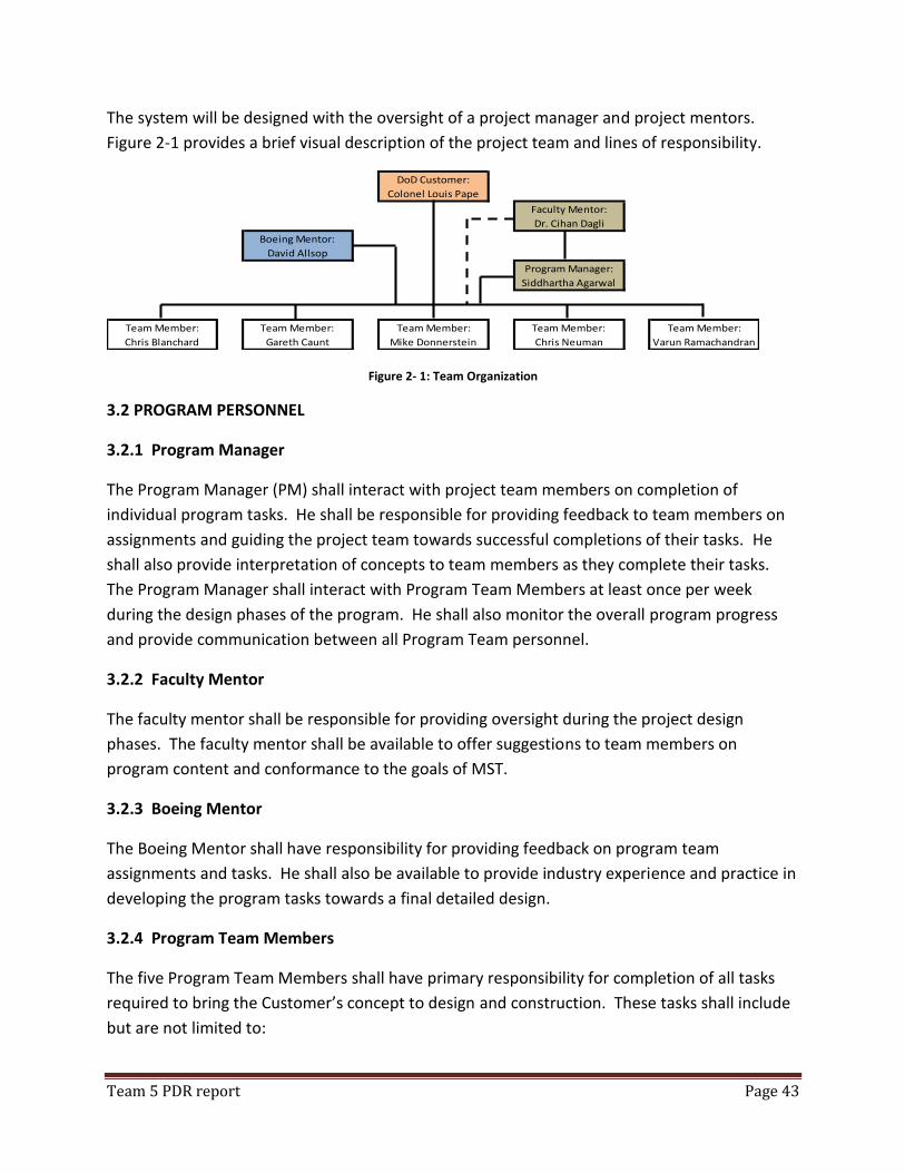
Team 5 PDR report Page 43
The system will be designed with the oversight of a project manager and project mentors.
Figure 2-1 provides a brief visual description of the project team and lines of responsibility.
DoD Customer:
Colonel Louis Pape
Faculty Mentor:
Dr. Cihan Dagli
Boeing Mentor:
David Allsop
Program Manager:
Siddhartha Agarwal
Team Member:
Chris Blanchard
Team Member:
Gareth Caunt
Team Member:
Mike Donnerstein
Team Member:
Chris Neuman
Team Member:
Varun Ramachandran
Figure 2- 1: Team Organization
3.2 PROGRAM PERSONNEL
3.2.1 Program Manager
The Program Manager (PM) shall interact with project team members on completion of
individual program tasks. He shall be responsible for providing feedback to team members on
assignments and guiding the project team towards successful completions of their tasks. He
shall also provide interpretation of concepts to team members as they complete their tasks.
The Program Manager shall interact with Program Team Members at least once per week
during the design phases of the program. He shall also monitor the overall program progress
and provide communication between all Program Team personnel.
3.2.2 Faculty Mentor
The faculty mentor shall be responsible for providing oversight during the project design
phases. The faculty mentor shall be available to offer suggestions to team members on
program content and conformance to the goals of MST.
3.2.3 Boeing Mentor
The Boeing Mentor shall have responsibility for providing feedback on program team
assignments and tasks. He shall also be available to provide industry experience and practice in
developing the program tasks towards a final detailed design.
3.2.4 Program Team Members
The five Program Team Members shall have primary responsibility for completion of all tasks
required to bring the Customer’s concept to design and construction. These tasks shall include
but are not limited to:
Team 5 PDR report Page 44
Requirements Development
Feasibility Analysis
Trade Studies
Work Breakdown Structure
Risk Assessment
Life Cycle Cost Analysis
Operational Feasibility Analysis
Development of Technical Performance Measurements
Project Scheduling
Software Design
Hardware Selection
Field Testing
Training
3.3 SCHEDULE MANAGEMENT
3.4 CUSTOMER COMMUNICATION AND CONTACT PROTOCOL
3.5 COST MANAGEMENT AND AFFORDABILITY
3.6 RISKS AND OPPORTUNITIES
3.7 VENDOR AND SUPPLIER MANAGEMENT PLANS
4.0 PROGRAM RESOURCES SUMMARY
4.1 STAFFING REQUIREMENTS
4.2 FACILITIES REQUIREMENTS
4.3 LEGACY EQUIPMENT REQUIREMENTS
4.3.1 Missouri MOTE System

Team 5 PDR report Page 45
4.3.2 Bioharness System
The BioHarness system, manufactured by Zephyr, is worn on each soldier’s chest and contains the
biometric sensors and the accelerometers. Data sensed by the BioHarness is collected internally and
transmitted via Bluetooth technology. Hardware is provided to interface and communicate with the
Missouri Mote.
4.3.3 Virtual Cultural Monitoring System
The Virtual Cultural Monitoring System provides capture of motion and body position by
utilizing small potentiometers impregnated in a compression type long sleeve shirt and gloves.
Figure XX demonstrates these items.
4.3.4 RT-19 Tactor Feedback System This system is a harness worn under typical military or civilian clothing. It includes sixteen (16) vibration motors arranged on the soldier’s abdomen and chest. These motors can be triggered by the trainer in the control room to convey feedback or commands to the soldiers.
Team 5 PDR report Page 46
5.0 ENVIRONMENT, HEALTH AND SAFETY
5.1 SAFETY CONCERNS
5.2 ENVIRONMENTAL CONCERNS
5.2.1 Use of Green Materials
5.2.2 Disposability of System
5.2.3 Hazardous Materials Handling Protocol
5.3 ERGONOMICS
Team 5 PDR report Page 47
Appendix B – Software Development
Pseudo Code Start exercise Initialization of default data values Health initialization Faux pas initialization Load soldier user data Gather real time data Gather gesture data Evaluate gesture type if gesture active == true Record gesture type GUI alert for trainer Tactile response == true end if data connection == lost Buffer data in relay router End Gather health data Gather location data Mux data Send data to data relay router Operate on data Forward data to repository / laptop Take data and transfer to graphical user interface
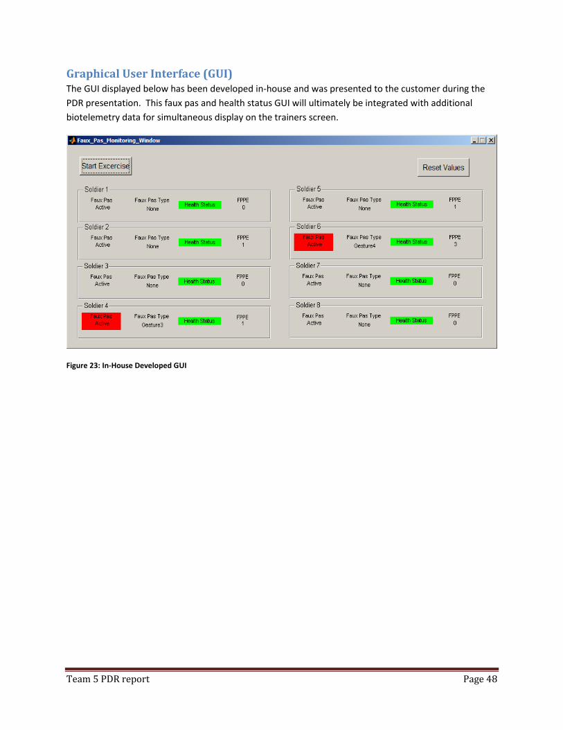
Team 5 PDR report Page 48
Graphical User Interface (GUI) The GUI displayed below has been developed in-house and was presented to the customer during the
PDR presentation. This faux pas and health status GUI will ultimately be integrated with additional
biotelemetry data for simultaneous display on the trainers screen.
Figure 23: In-House Developed GUI
Team 5 PDR report Page 49
Appendix C – Operational Feasibility
Safety Definition
According to CMMI +SAFE V1.2 (TECHNICAL NOTE CMU/SEI-2007-TN-006 Carnegie Mellon March 2007),
Safety can be defined as “An acceptable level of risk. Absolute safety (i.e., zero risk) is not generally
achievable. Therefore, we define safety in terms of the level of risk that is deemed acceptable.”
According to MIL-STD-882E, Safety can be defined as “Freedom from conditions that can cause death,
injury, occupational illness, damage to or loss of equipment or property, or damage to the environment.”
For the purposes of this report, safety will be defined as the expectation that the system, under defined
conditions, does not increase the risk of death, injury, occupational illness, damage to or loss to
property, loss of system availability, or damage to the environment above an acceptable level.
Technical Performance Measures
We will undertake a series of safety and hazard analyses throughout the system lifecycle. These will be
in accordance with an agreed standard with the customer and will need to address customer specific
safety articles, university safety guidelines, and any relevant government safety regulation. The analysis
will need to be reviewed by safety subject matter expert or experts to ensure that all required aspects of
safety and hazards have been addressed.
The safety analyses will include a hazard list that is maintained throughout the lifecycle and include
system and subsystem hazards, a maintained hazard analysis that determines casual links and
mitigations at both the system and subsystem levels, analysis of all changes to the system to ensure that
system safety is not compromised, and investigations into all mishaps and near misses. Reporting and
investigations of near misses is particularly important as they can be used to prevent mishaps in the
future.
Analysis approach
The safety and hazard analyses will use a risk based approach. The level of risk will be assessed using a
Risk Assessment Matrix (see Table 3 below). The matrix is generated by using the severity of a potential
mishap against the probability it will occur. The tables below are taken from MIL-STD-882E.
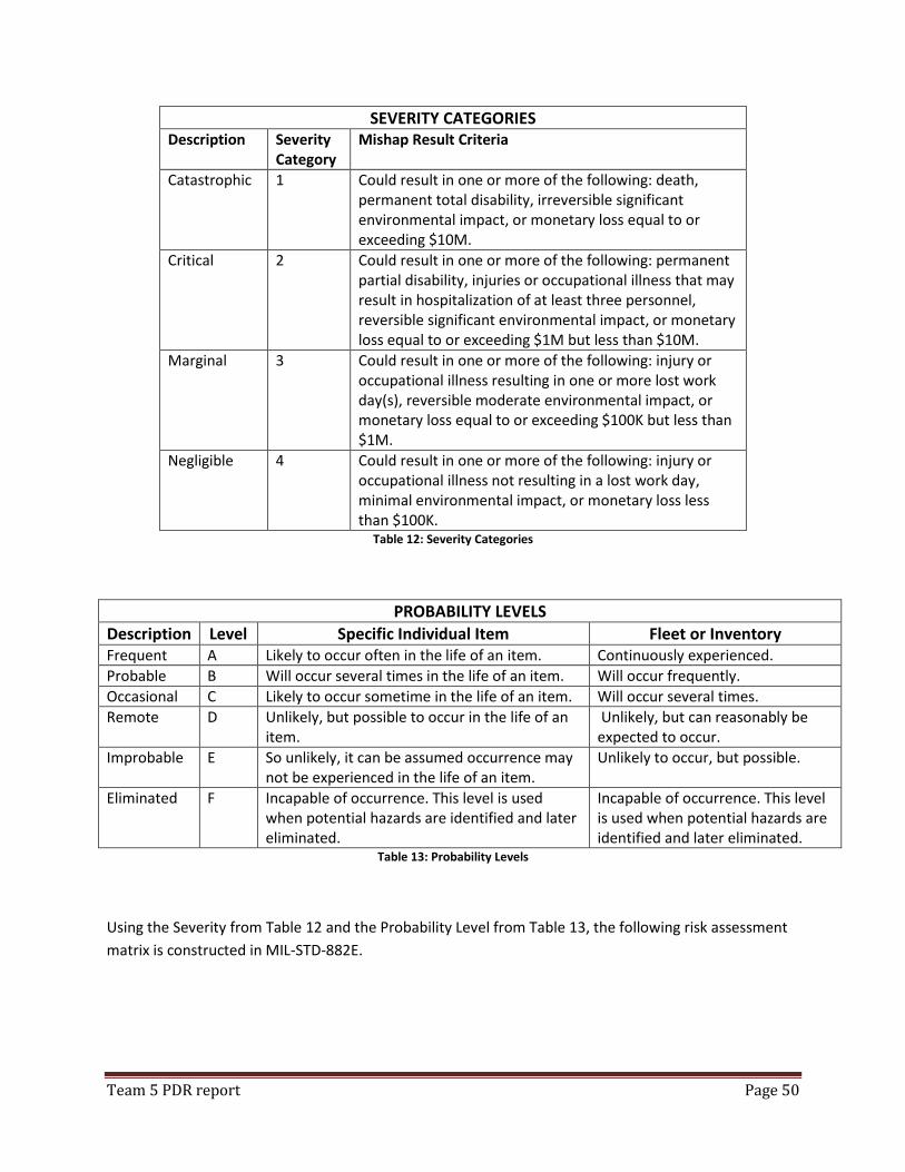
Team 5 PDR report Page 50
SEVERITY CATEGORIES Description Severity
Category Mishap Result Criteria
Catastrophic 1 Could result in one or more of the following: death, permanent total disability, irreversible significant environmental impact, or monetary loss equal to or exceeding $10M.
Critical 2 Could result in one or more of the following: permanent partial disability, injuries or occupational illness that may result in hospitalization of at least three personnel, reversible significant environmental impact, or monetary loss equal to or exceeding $1M but less than $10M.
Marginal 3 Could result in one or more of the following: injury or occupational illness resulting in one or more lost work day(s), reversible moderate environmental impact, or monetary loss equal to or exceeding $100K but less than $1M.
Negligible 4 Could result in one or more of the following: injury or occupational illness not resulting in a lost work day, minimal environmental impact, or monetary loss less than $100K.
Table 12: Severity Categories
PROBABILITY LEVELS
Description Level Specific Individual Item Fleet or Inventory Frequent A Likely to occur often in the life of an item. Continuously experienced.
Probable B Will occur several times in the life of an item. Will occur frequently.
Occasional C Likely to occur sometime in the life of an item. Will occur several times.
Remote D Unlikely, but possible to occur in the life of an item.
Unlikely, but can reasonably be expected to occur.
Improbable E So unlikely, it can be assumed occurrence may not be experienced in the life of an item.
Unlikely to occur, but possible.
Eliminated F Incapable of occurrence. This level is used when potential hazards are identified and later eliminated.
Incapable of occurrence. This level is used when potential hazards are identified and later eliminated.
Table 13: Probability Levels
Using the Severity from Table 12 and the Probability Level from Table 13, the following risk assessment
matrix is constructed in MIL-STD-882E.
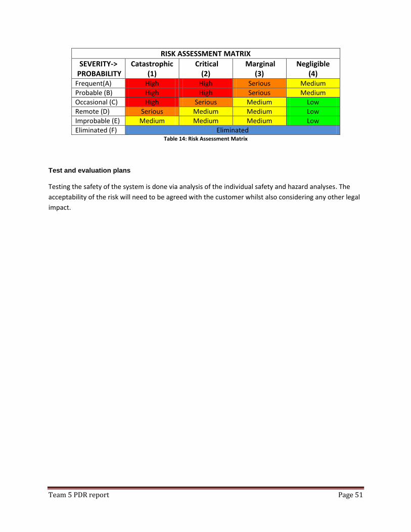
Team 5 PDR report Page 51
RISK ASSESSMENT MATRIX
SEVERITY-> PROBABILITY
Catastrophic (1)
Critical (2)
Marginal (3)
Negligible (4)
Frequent(A) High High Serious Medium
Probable (B) High High Serious Medium
Occasional (C) High Serious Medium Low
Remote (D) Serious Medium Medium Low
Improbable (E) Medium Medium Medium Low
Eliminated (F) Eliminated Table 14: Risk Assessment Matrix
Test and evaluation plans
Testing the safety of the system is done via analysis of the individual safety and hazard analyses. The
acceptability of the risk will need to be agreed with the customer whilst also considering any other legal
impact.
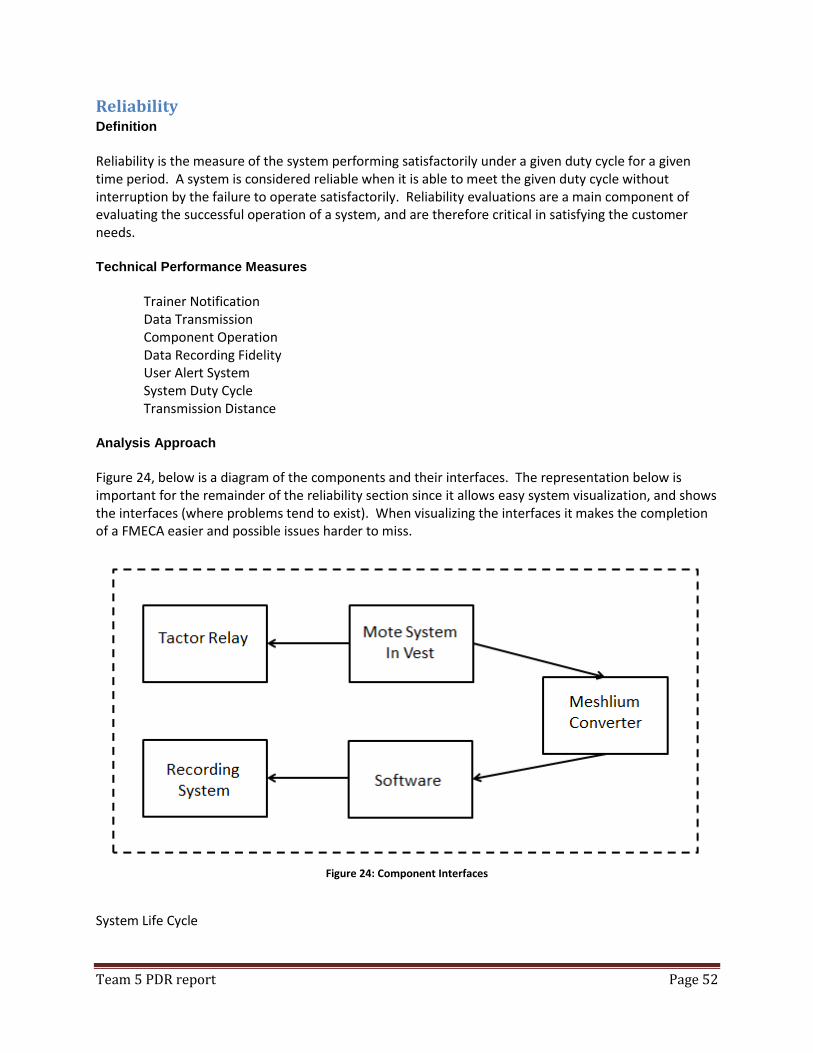
Team 5 PDR report Page 52
Reliability Definition
Reliability is the measure of the system performing satisfactorily under a given duty cycle for a given time period. A system is considered reliable when it is able to meet the given duty cycle without interruption by the failure to operate satisfactorily. Reliability evaluations are a main component of evaluating the successful operation of a system, and are therefore critical in satisfying the customer needs. Technical Performance Measures
Trainer Notification
Data Transmission Component Operation Data Recording Fidelity User Alert System System Duty Cycle Transmission Distance Analysis Approach
Figure 24, below is a diagram of the components and their interfaces. The representation below is important for the remainder of the reliability section since it allows easy system visualization, and shows the interfaces (where problems tend to exist). When visualizing the interfaces it makes the completion of a FMECA easier and possible issues harder to miss.
Figure 24: Component Interfaces
System Life Cycle
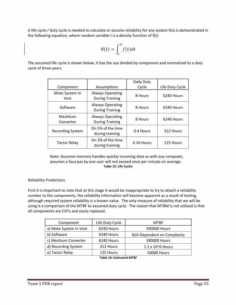
Team 5 PDR report Page 53
A life cycle / duty cycle is needed to calculate or assume reliability for any system this is demonstrated in the following equation, where random variable t is a density function of f(t):
( ) ∫ ( )
The assumed life cycle is shown below, it has the use divided by component and normalized to a duty cycle of three years.
Component Assumptions Daily Duty
Cycle Life Duty Cycle
Mote System In Vest
Always Operating During Training
8 Hours 6240 Hours
Software Always Operating
During Training 8 Hours 6240 Hours
Meshlium Converter
Always Operating During Training
8 Hours 6240 Hours
Recording System On 5% of the time
during training 0.4 Hours 312 Hours
Tactor Relay On 2% of the time
during training 0.16 Hours 125 Hours
Note: Assumes memory handles quickly incoming data as with any computer, assumes a faux pas by one user will not exceed once per minute on average.
Table 15: Life Cycles
Reliability Predictions First it is important to note that at this stage it would be inappropriate to try to attach a reliability number to the components, the reliability information will become apparent as a result of testing, although required system reliability is a known value. The only measure of reliability that we will be using is a comparison of the MTBF to assumed duty cycle. The reason that MTBM is not utilized is that all components are COTs and easily replaced.
Component Life Duty Cycle MTBF
a) Mote System In Vest 6240 Hours 390000 Hours
b) Software 6240 Hours N/A Dependent on Complexity
c) Meshium Converter 6240 Hours 390000 Hours
d) Recording System 312 Hours 1.2 x 10^6 Hours
e) Tactor Relay 125 Hours 50000 Hours Table 16: Estimated MTBF
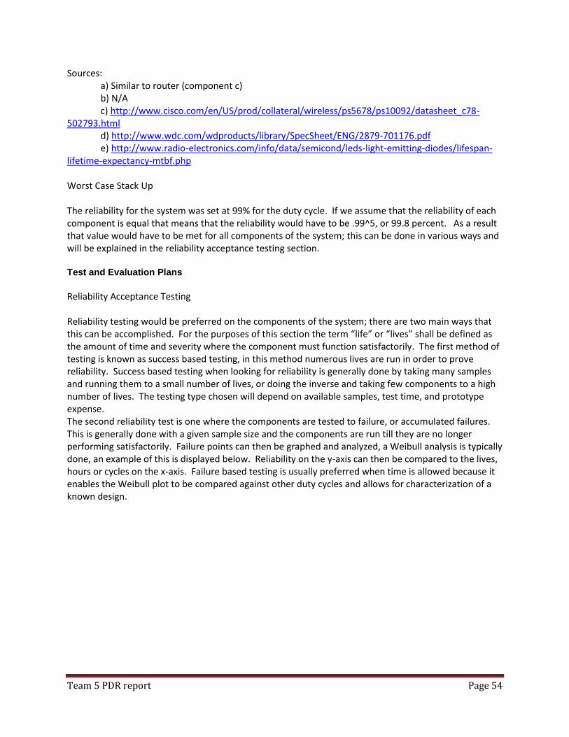
Team 5 PDR report Page 54
Sources: a) Similar to router (component c) b) N/A c) http://www.cisco.com/en/US/prod/collateral/wireless/ps5678/ps10092/datasheet_c78-502793.html d) http://www.wdc.com/wdproducts/library/SpecSheet/ENG/2879-701176.pdf e) http://www.radio-electronics.com/info/data/semicond/leds-light-emitting-diodes/lifespan-lifetime-expectancy-mtbf.php Worst Case Stack Up The reliability for the system was set at 99% for the duty cycle. If we assume that the reliability of each component is equal that means that the reliability would have to be .99^5, or 99.8 percent. As a result that value would have to be met for all components of the system; this can be done in various ways and will be explained in the reliability acceptance testing section. Test and Evaluation Plans
Reliability Acceptance Testing Reliability testing would be preferred on the components of the system; there are two main ways that this can be accomplished. For the purposes of this section the term “life” or “lives” shall be defined as the amount of time and severity where the component must function satisfactorily. The first method of testing is known as success based testing, in this method numerous lives are run in order to prove reliability. Success based testing when looking for reliability is generally done by taking many samples and running them to a small number of lives, or doing the inverse and taking few components to a high number of lives. The testing type chosen will depend on available samples, test time, and prototype expense. The second reliability test is one where the components are tested to failure, or accumulated failures. This is generally done with a given sample size and the components are run till they are no longer performing satisfactorily. Failure points can then be graphed and analyzed, a Weibull analysis is typically done, an example of this is displayed below. Reliability on the y-axis can then be compared to the lives, hours or cycles on the x-axis. Failure based testing is usually preferred when time is allowed because it enables the Weibull plot to be compared against other duty cycles and allows for characterization of a known design.
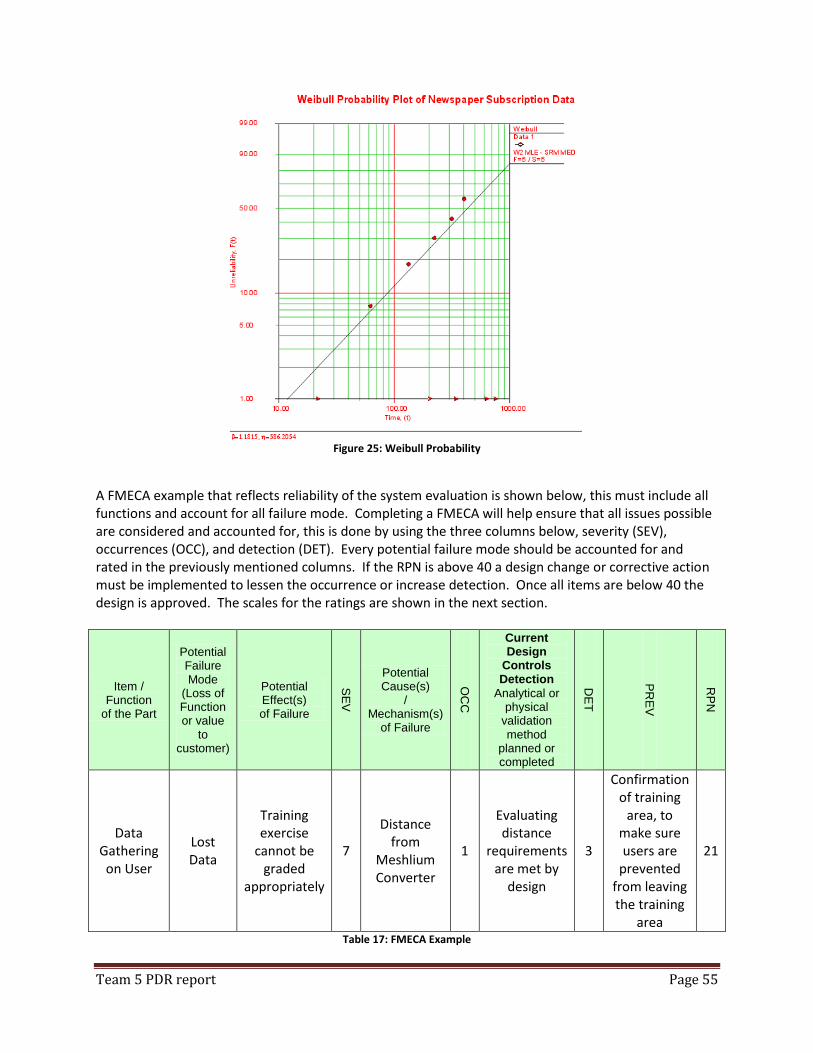
Team 5 PDR report Page 55
Figure 25: Weibull Probability
A FMECA example that reflects reliability of the system evaluation is shown below, this must include all functions and account for all failure mode. Completing a FMECA will help ensure that all issues possible are considered and accounted for, this is done by using the three columns below, severity (SEV), occurrences (OCC), and detection (DET). Every potential failure mode should be accounted for and rated in the previously mentioned columns. If the RPN is above 40 a design change or corrective action must be implemented to lessen the occurrence or increase detection. Once all items are below 40 the design is approved. The scales for the ratings are shown in the next section.
Item / Function
of the Part
Potential Failure Mode
(Loss of Function or value
to customer)
Potential Effect(s) of Failure
SE
V
Potential Cause(s)
/ Mechanism(s)
of Failure
OC
C
Current Design
Controls Detection
Analytical or physical
validation method
planned or completed
DE
T
PR
EV
RP
N
Data Gathering on User
Lost Data
Training exercise
cannot be graded
appropriately
7
Distance from
Meshlium Converter
1
Evaluating distance
requirements are met by
design
3
Confirmation of training
area, to make sure users are
prevented from leaving the training
area
21
Table 17: FMECA Example
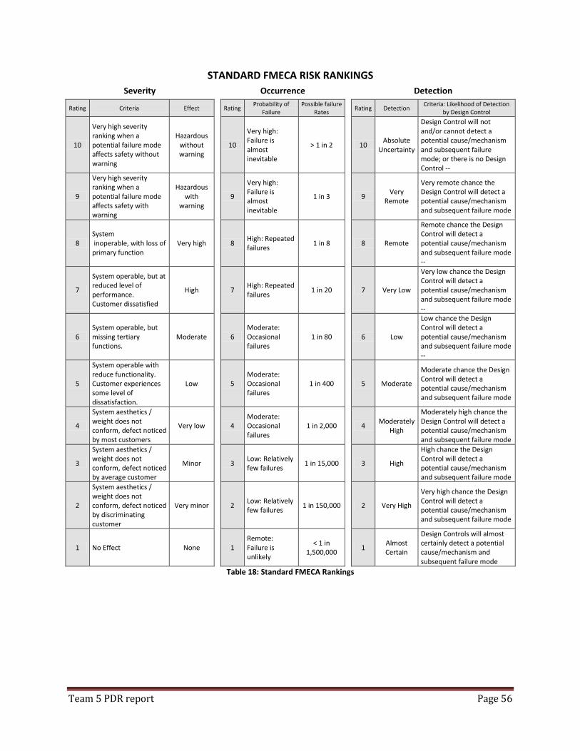
Team 5 PDR report Page 56
STANDARD FMECA RISK RANKINGS
Severity
Occurrence
Detection
Rating Criteria Effect
Rating Probability of
Failure Possible failure
Rates Rating Detection
Criteria: Likelihood of Detection by Design Control
10
Very high severity ranking when a potential failure mode affects safety without warning
Hazardous without warning
10
Very high: Failure is almost inevitable
> 1 in 2
10 Absolute
Uncertainty
Design Control will not and/or cannot detect a potential cause/mechanism and subsequent failure mode; or there is no Design Control --
9
Very high severity ranking when a potential failure mode affects safety with warning
Hazardous with
warning
9
Very high: Failure is almost inevitable
1 in 3
9 Very
Remote
Very remote chance the Design Control will detect a potential cause/mechanism and subsequent failure mode
8 System inoperable, with loss of primary function
Very high
8 High: Repeated failures
1 in 8
8 Remote
Remote chance the Design Control will detect a potential cause/mechanism and subsequent failure mode --
7
System operable, but at reduced level of performance. Customer dissatisfied
High
7 High: Repeated failures
1 in 20
7 Very Low
Very low chance the Design Control will detect a potential cause/mechanism and subsequent failure mode --
6 System operable, but missing tertiary functions.
Moderate
6 Moderate: Occasional failures
1 in 80
6 Low
Low chance the Design Control will detect a potential cause/mechanism and subsequent failure mode --
5
System operable with reduce functionality. Customer experiences some level of dissatisfaction.
Low
5 Moderate: Occasional failures
1 in 400
5 Moderate
Moderate chance the Design Control will detect a potential cause/mechanism and subsequent failure mode
4
System aesthetics / weight does not conform, defect noticed by most customers
Very low
4 Moderate: Occasional failures
1 in 2,000
4 Moderately
High
Moderately high chance the Design Control will detect a potential cause/mechanism and subsequent failure mode
3
System aesthetics / weight does not conform, defect noticed by average customer
Minor
3 Low: Relatively few failures
1 in 15,000
3 High
High chance the Design Control will detect a potential cause/mechanism and subsequent failure mode
2
System aesthetics / weight does not conform, defect noticed by discriminating customer
Very minor
2 Low: Relatively few failures
1 in 150,000
2 Very High
Very high chance the Design Control will detect a potential cause/mechanism and subsequent failure mode
1 No Effect None
1 Remote: Failure is unlikely
< 1 in 1,500,000
1 Almost Certain
Design Controls will almost certainly detect a potential cause/mechanism and subsequent failure mode
Table 18: Standard FMECA Rankings
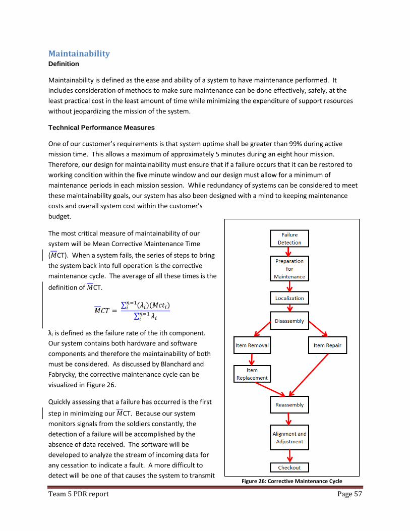
Team 5 PDR report Page 57
Maintainability Definition
Maintainability is defined as the ease and ability of a system to have maintenance performed. It
includes consideration of methods to make sure maintenance can be done effectively, safely, at the
least practical cost in the least amount of time while minimizing the expenditure of support resources
without jeopardizing the mission of the system.
Technical Performance Measures
One of our customer’s requirements is that system uptime shall be greater than 99% during active
mission time. This allows a maximum of approximately 5 minutes during an eight hour mission.
Therefore, our design for maintainability must ensure that if a failure occurs that it can be restored to
working condition within the five minute window and our design must allow for a minimum of
maintenance periods in each mission session. While redundancy of systems can be considered to meet
these maintainability goals, our system has also been designed with a mind to keeping maintenance
costs and overall system cost within the customer’s
budget.
The most critical measure of maintainability of our
system will be Mean Corrective Maintenance Time
( CT). When a system fails, the series of steps to bring
the system back into full operation is the corrective
maintenance cycle. The average of all these times is the
definition of CT.
∑ ( )( )
∑
λi is defined as the failure rate of the ith component.
Our system contains both hardware and software
components and therefore the maintainability of both
must be considered. As discussed by Blanchard and
Fabrycky, the corrective maintenance cycle can be
visualized in Figure 26.
Quickly assessing that a failure has occurred is the first
step in minimizing our CT. Because our system
monitors signals from the soldiers constantly, the
detection of a failure will be accomplished by the
absence of data received. The software will be
developed to analyze the stream of incoming data for
any cessation to indicate a fault. A more difficult to
detect will be one of that causes the system to transmit Figure 26: Corrective Maintenance Cycle
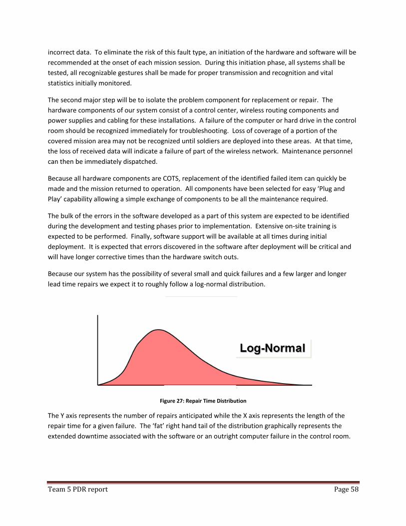
Team 5 PDR report Page 58
incorrect data. To eliminate the risk of this fault type, an initiation of the hardware and software will be
recommended at the onset of each mission session. During this initiation phase, all systems shall be
tested, all recognizable gestures shall be made for proper transmission and recognition and vital
statistics initially monitored.
The second major step will be to isolate the problem component for replacement or repair. The
hardware components of our system consist of a control center, wireless routing components and
power supplies and cabling for these installations. A failure of the computer or hard drive in the control
room should be recognized immediately for troubleshooting. Loss of coverage of a portion of the
covered mission area may not be recognized until soldiers are deployed into these areas. At that time,
the loss of received data will indicate a failure of part of the wireless network. Maintenance personnel
can then be immediately dispatched.
Because all hardware components are COTS, replacement of the identified failed item can quickly be
made and the mission returned to operation. All components have been selected for easy ‘Plug and
Play’ capability allowing a simple exchange of components to be all the maintenance required.
The bulk of the errors in the software developed as a part of this system are expected to be identified
during the development and testing phases prior to implementation. Extensive on-site training is
expected to be performed. Finally, software support will be available at all times during initial
deployment. It is expected that errors discovered in the software after deployment will be critical and
will have longer corrective times than the hardware switch outs.
Because our system has the possibility of several small and quick failures and a few larger and longer
lead time repairs we expect it to roughly follow a log-normal distribution.
Figure 27: Repair Time Distribution
The Y axis represents the number of repairs anticipated while the X axis represents the length of the
repair time for a given failure. The ‘fat’ right hand tail of the distribution graphically represents the
extended downtime associated with the software or an outright computer failure in the control room.
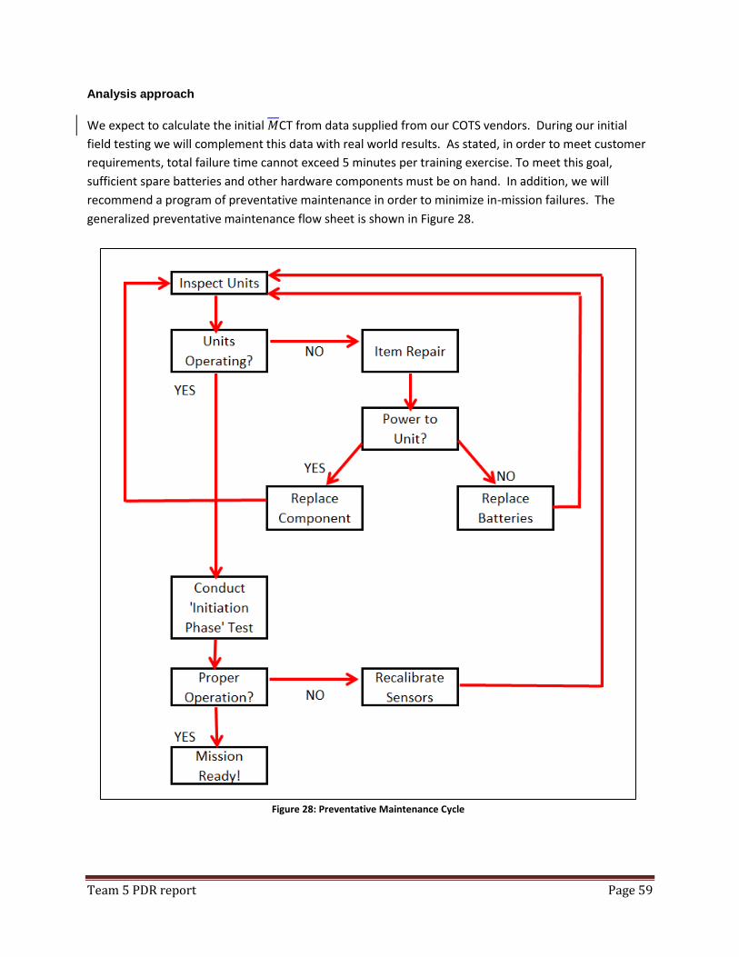
Team 5 PDR report Page 59
Analysis approach
We expect to calculate the initial CT from data supplied from our COTS vendors. During our initial
field testing we will complement this data with real world results. As stated, in order to meet customer
requirements, total failure time cannot exceed 5 minutes per training exercise. To meet this goal,
sufficient spare batteries and other hardware components must be on hand. In addition, we will
recommend a program of preventative maintenance in order to minimize in-mission failures. The
generalized preventative maintenance flow sheet is shown in Figure 28.
Figure 28: Preventative Maintenance Cycle

Team 5 PDR report Page 60
This preventative maintenance procedure will be recommend for implementation prior to each mission
each day.
Routine preventative and general maintenance tasks will be the responsibility of the trainers and
military staff. However, during initial roll-out of the system, the team will be on-site to conduct training
on the steps to be taken. A preliminary version of maintenance tasks to be completed is listed below in
Table 19.
Description of Task Frequency Responsible Party
Removal of Batteries for Charging Daily / Post Mission Training Support Staff
System power-up Daily / Post Mission Trainer
System Capability Test Daily / Pre-Mission Trainer
Data Back-up Weekly Trainer
Component Physical Inspection Quarterly Training Support Staff Table 19: Typical Maintenance Tasks
Test and evaluation plans
Evaluation of our estimates for will not be possible until the system is deployed in the field and
mission results can be analyzed. However during our initial testing we should be able to arrive at a
reasonably accurate Mean Corrective Time and use this to determine expected availability for the
customer.
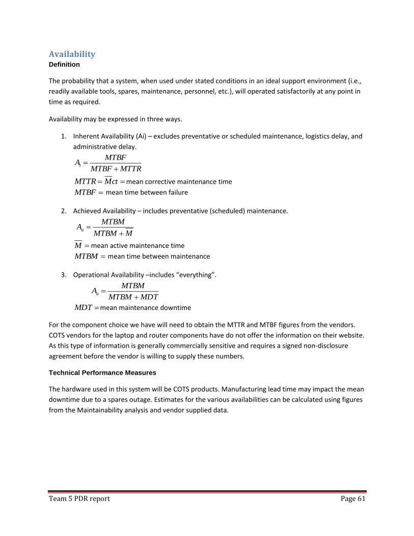
Team 5 PDR report Page 61
Availability Definition
The probability that a system, when used under stated conditions in an ideal support environment (i.e.,
readily available tools, spares, maintenance, personnel, etc.), will operated satisfactorily at any point in
time as required.
Availability may be expressed in three ways.
1. Inherent Availability (Ai) – excludes preventative or scheduled maintenance, logistics delay, and
administrative delay.
MTTRMTBF
MTBFAi
ctMMTTR mean corrective maintenance time
MTBF mean time between failure
2. Achieved Availability – includes preventative (scheduled) maintenance.
MMTBM
MTBMAa
M mean active maintenance time
MTBM mean time between maintenance
3. Operational Availability –includes “everything”.
MDTMTBM
MTBMAo
MDT mean maintenance downtime
For the component choice we have will need to obtain the MTTR and MTBF figures from the vendors.
COTS vendors for the laptop and router components have do not offer the information on their website.
As this type of information is generally commercially sensitive and requires a signed non-disclosure
agreement before the vendor is willing to supply these numbers.
Technical Performance Measures
The hardware used in this system will be COTS products. Manufacturing lead time may impact the mean
downtime due to a spares outage. Estimates for the various availabilities can be calculated using figures
from the Maintainability analysis and vendor supplied data.
Team 5 PDR report Page 62
Analysis approach
An initial estimate of the various availabilities will be created once the various input measures are
available using the formulas in the definition section. These estimates will be updated with actual data
as it becomes available. Actual values for availability measures can only be calculated after a sustained
period of operations provide actual measures for MTBF, MTTR, MTBM, M, and MDT.
Test and evaluation plans
The calculated values for availability will be tested by simulating failures and testing maintenance
personnel’s ability to diagnose and correct those failures.
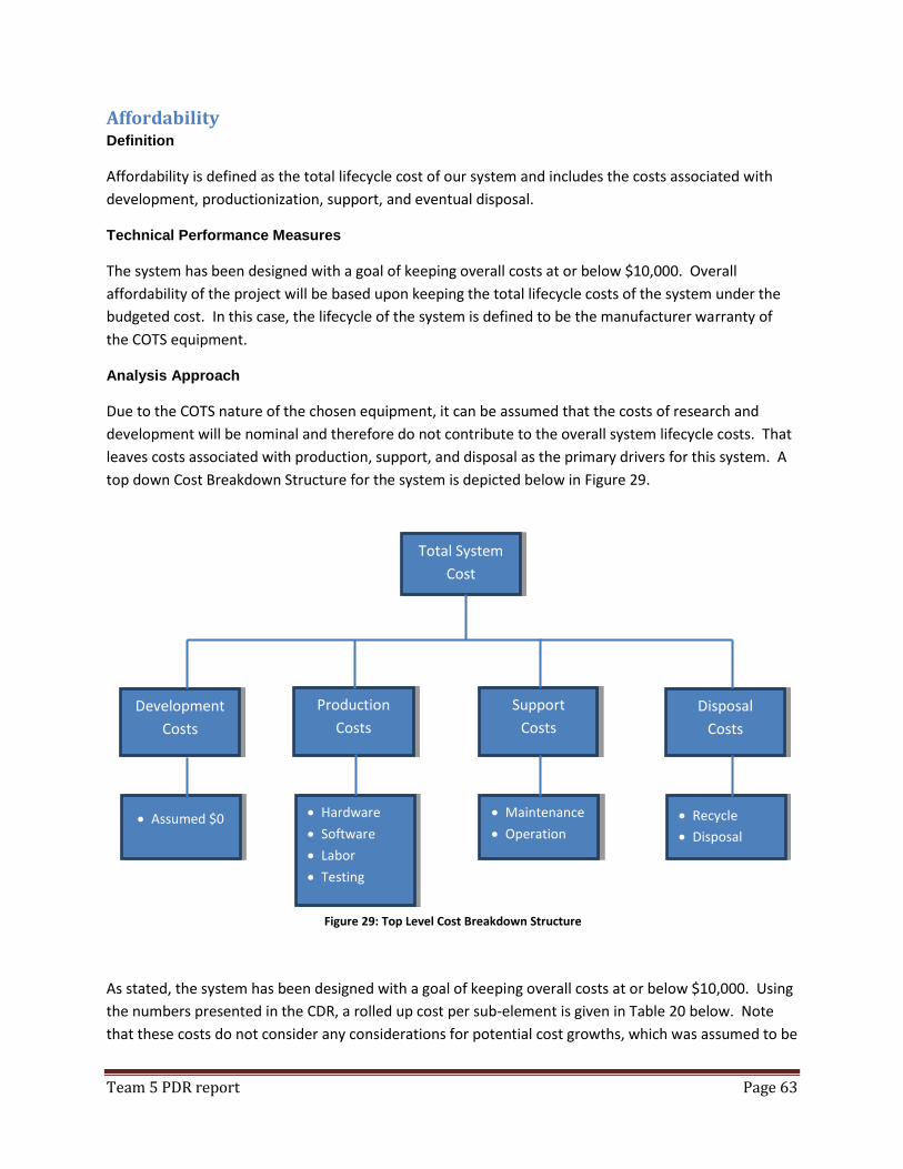
Team 5 PDR report Page 63
Affordability Definition
Affordability is defined as the total lifecycle cost of our system and includes the costs associated with
development, productionization, support, and eventual disposal.
Technical Performance Measures
The system has been designed with a goal of keeping overall costs at or below $10,000. Overall
affordability of the project will be based upon keeping the total lifecycle costs of the system under the
budgeted cost. In this case, the lifecycle of the system is defined to be the manufacturer warranty of
the COTS equipment.
Analysis Approach
Due to the COTS nature of the chosen equipment, it can be assumed that the costs of research and
development will be nominal and therefore do not contribute to the overall system lifecycle costs. That
leaves costs associated with production, support, and disposal as the primary drivers for this system. A
top down Cost Breakdown Structure for the system is depicted below in Figure 29.
As stated, the system has been designed with a goal of keeping overall costs at or below $10,000. Using
the numbers presented in the CDR, a rolled up cost per sub-element is given in Table 20 below. Note
that these costs do not consider any considerations for potential cost growths, which was assumed to be
Total System
Cost
Development
Costs
Production
Costs
Support
Costs
Assumed $0
Disposal
Costs
Recycle
Disposal
Hardware
Software
Labor
Testing
Maintenance
Operation
Figure 29: Top Level Cost Breakdown Structure

Team 5 PDR report Page 64
10% in order to cover unanticipated modifications. Because many of the elements of cost remain initial
estimates, there is a significant risk of cost increases due to engineering changes and unforeseen issues.
Phase Subelement Cost
Development $0
Production $7,908
Support $450
Disposal $150
TOTAL $8,508 Table 20: Rolled-Up Sub-Element Costs
This clearly shows that the bulk of overall system costs are incurred in the production phase. A broken
out cost structure for productions is shown in Table 21.
Production Phase Individual Cost
Hardware $4,458
Software $1,200
Testing $500
Training $500
Miscellaneous $1,250
Production Total $7,908 Table 21: Production Cost Breakdown
Maintenance personnel will be required to provide periodic support for the maintainability of the
system. While this is not a nominal expense, it assumed that these personnel will not be funded out of
the budget for this system.
Test and Evaluation Plans
Expenditures will be tracked over the lifecycle of the project. Because the bulk of project expenditures
are expected in the production phase, we should know if the system will be within budget prior to
entering the support and disposal phases. As such, assumptions for support and disposal costs will be
used when determining the affordability of the system.
Supportability Definition
Supportability refers to the inherent characteristics of design and installation that enable the effective
and efficient maintenance and support of the system throughout its planned life cycle.
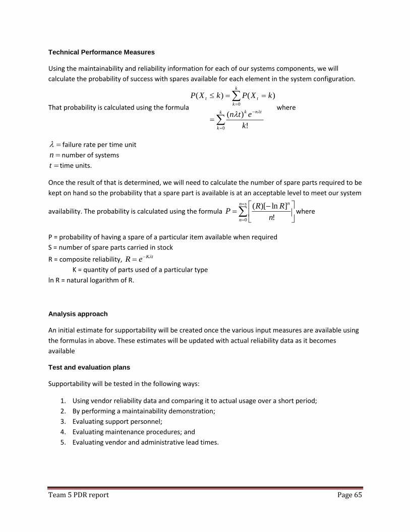
Team 5 PDR report Page 65
Technical Performance Measures
Using the maintainability and reliability information for each of our systems components, we will
calculate the probability of success with spares available for each element in the system configuration.
That probability is calculated using the formula
k
k
tnk
k
k
tt
k
etn
kXPkXP
0
0
!
)(
)()(
where
failure rate per time unit
n number of systems
t time units.
Once the result of that is determined, we will need to calculate the number of spare parts required to be
kept on hand so the probability that a spare part is available is at an acceptable level to meet our system
availability. The probability is calculated using the formula
sn
n
n
n
RRP
0 !
]ln)[(where
P = probability of having a spare of a particular item available when required
S = number of spare parts carried in stock
R = composite reliability, tKeR
K = quantity of parts used of a particular type
ln R = natural logarithm of R.
Analysis approach
An initial estimate for supportability will be created once the various input measures are available using
the formulas in above. These estimates will be updated with actual reliability data as it becomes
available
Test and evaluation plans
Supportability will be tested in the following ways:
1. Using vendor reliability data and comparing it to actual usage over a short period;
2. By performing a maintainability demonstration;
3. Evaluating support personnel;
4. Evaluating maintenance procedures; and
5. Evaluating vendor and administrative lead times.
Team 5 PDR report Page 66
Disposability Definition
The concept of disposability is concerned with the termination /elimination of a system after completing
its life-cycle. It is an important design dependent parameter in product development. The system or
product after serving its life cycle is exposed to the possibility of being completely terminated or can be
recycled depending upon the utilization.
Technical Performance Measures
Green Product: should be such that at the end of its useful life passes through disassembly and
other reclamation processes to reuse non-hazardous and renewable materials.
Clean processes: Process of development or building the system should minimize the use of
natural resources, minimize generation of wastes, and minimize usage of power.
Eco factory: Physical location where the device or the system is developed or manufactures. It
focuses on implementing environmental conscious approach (ECDM).
Analysis approach
It is a system life cycle approach that aims at maintaining an effective and sustainable environment. The
disposability function can be achieved either by eliminating the entire system/product or by
reusing/recycling parts of the system which has some capabilities. The advantage of recycling is that it
results in reduced disposal costs and increasing total product value.
The disposability of our system will be carried out in the following way:
The system is divided into obsolete components (not technically feasible), phased out
components, and non-repairable failed components.
All of these components are evaluated and based on the classification above, we determine if
we have to either recycle the components or dispose completely.
The components are then put in categories depending on their reusability. Components which
are not usable are disposed or recycled.
Components that are reusable are again used in the system. The components which are partially
reusable or reusable after modification are then evaluated again and a decision is made to
dispose the ones that require a lot of modification.
Finally the disposed components are checked for environmental impacts and are exterminated.
Team 5 PDR report Page 67
Test and evaluation plans
Recycling: Is a major factor in disposability and we have requirements addressing a critical
percentage of components or materials which have to be recycled.
Batteries are rechargeable and will work for 5 days a week for 45 weeks and will be
recycled.
Demanufacturing: Is the disassembly and recycling of obsolete products. The goal is to remove
and recycle every component used in our system somehow.
Recycling during production: Recycle the waste that is produced when the system is made or
built as far as possible.
Team 5 PDR report Page 68
Usability Definition
Usability can be defined as the extent of effectiveness and efficiency that a system can be used by its
specified users in its designed context. Usability is also interrelated with other aspects of operational
feasibility such as: maintainability, reliability, supportability, affordability and producibility.
Technical Performance Measures
Most of the usability requirements of our system are fulfilled by the individual legacy systems which are
incorporated into our monitoring and training system. These include weight of individual components,
ease of the soldiers donning the system, accuracy of sensors, etc.
However, the usability of our system will be measured in several different areas. These include
physiological factors, human sensory factors (primarily for the trainer), and operational factors.
Physiological Factors
o Temperature – training may be conducted in temperatures all temperature conditions.
The sensors, routers, and computer system must all have wide operating ranges.
o Humidity – Training may be performed outdoors and in all weather conditions.
Therefore humidity from zero to 100% is anticipated. The system must be weatherproof
enough to withstand this.
o Environmental Conditions – Similarly, training may be performed in all weather
conditions such as rain or snow. The wireless infrastructure must be stored in
enclosures that render it effectively isolated from these conditions or from dust
conditions that could be encountered in hotter weather.
Human Sensory Factors
o Visual – The training system should be designed so that the trainer can simultaneously
monitor at least eight (8) soldiers simultaneously. The displays will be designed in a
manner that each soldier’s health data is at all times visible. If any health alerts or faux
pas are detected, a visual indicator on the specific soldier must alert the trainer.
o Audible – Similarly, the monitoring system must alert the trainer to faux pas or health
situations with an audible alert so that action may be taken
o Tactile – The Tactor response system that is deployed on the soldiers must have a
distinct enough signature that the alert signaled by the trainer will allow the soldier to
distinguish whether a health alert, social faux pas, or combat faux pas has occurred.
Personnel Required
o The system design will allow a single trainer to be all that is required during system
operation.
o The system shall also be designed with COTS products so that maintenance tasks are
minimized and replacement is accomplished with plug and play components to limit the
number of maintenance personnel required when the system is idle.
Team 5 PDR report Page 69
o Training rate – the system shall be developed so that its trainer interface is intuitive.
This will minimize the amount of time and money that must be expended on training
prior to system implementation.
Analysis approach
The designed system shall be reviewed for the behavior characteristics that are necessary for the
operator to complete mission tasks. This operator task analysis will involve identifying the operator
related functions within the system. For each function or operator decision identified the specific
information that is required must be determined. The display of this information will be determined so
as to best alert the trainer to the data as well as to prioritize his response to multiple simultaneous data
alerts. For critical alerts, such as health status, backup alarms and active acknowledgement from the
trainer will be required. The required skill level of the trainer will be required to be of at least an
intermediate level.
Trainer error analysis is also recommended for system calibration and future versions of the system.
The errors will be classified as being due to inadequate physical layout or design, inadequate display or
transmission of training data, improper user interface for the trainer, or inadequate training for soldiers
or trainers prior to system implementation.
Test and evaluation plans
Evaluation of our estimates for the measures of usability will be verified after the system has been fully
developed and is ready for field testing. At that time the estimates for usability will be refined and
recorded.
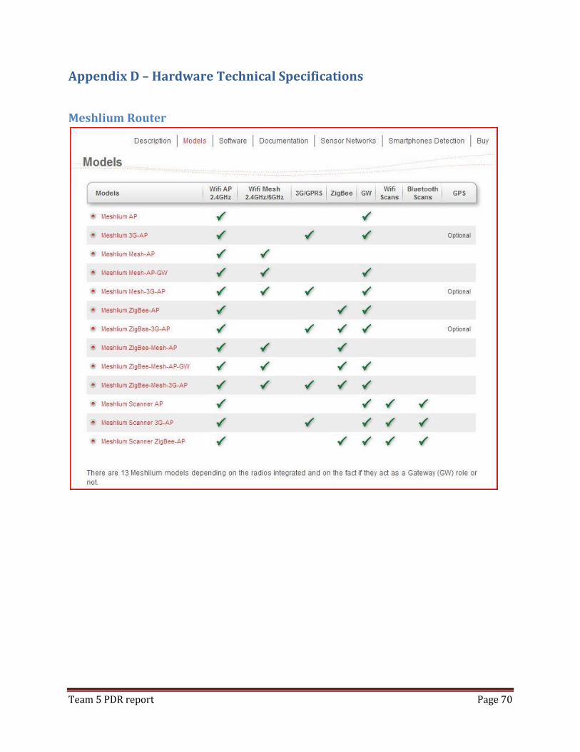
Team 5 PDR report Page 70
Appendix D – Hardware Technical Specifications
Meshlium Router
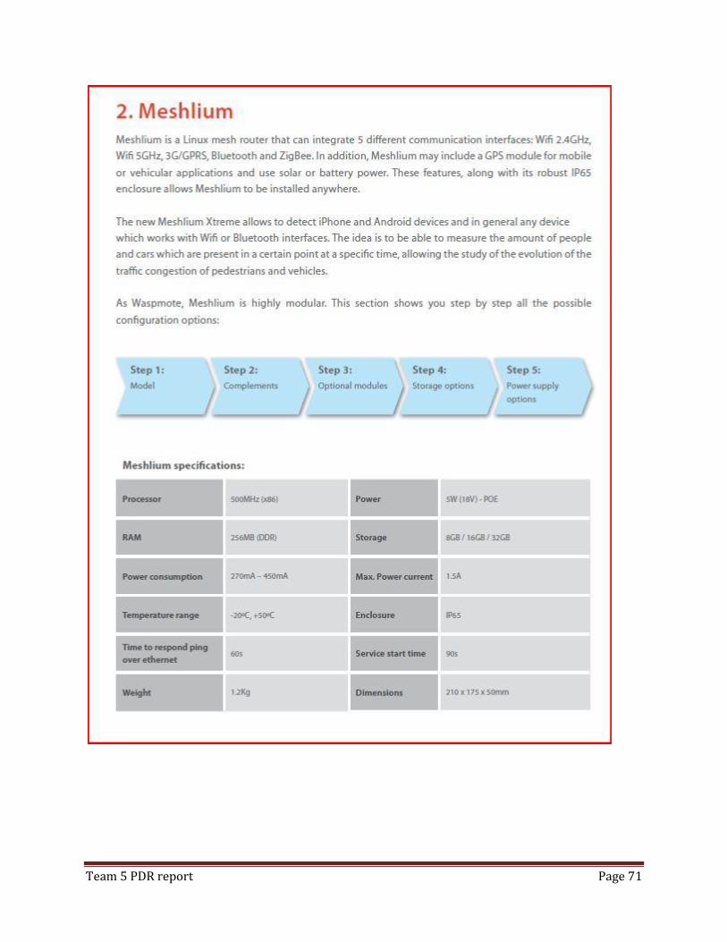
Team 5 PDR report Page 71
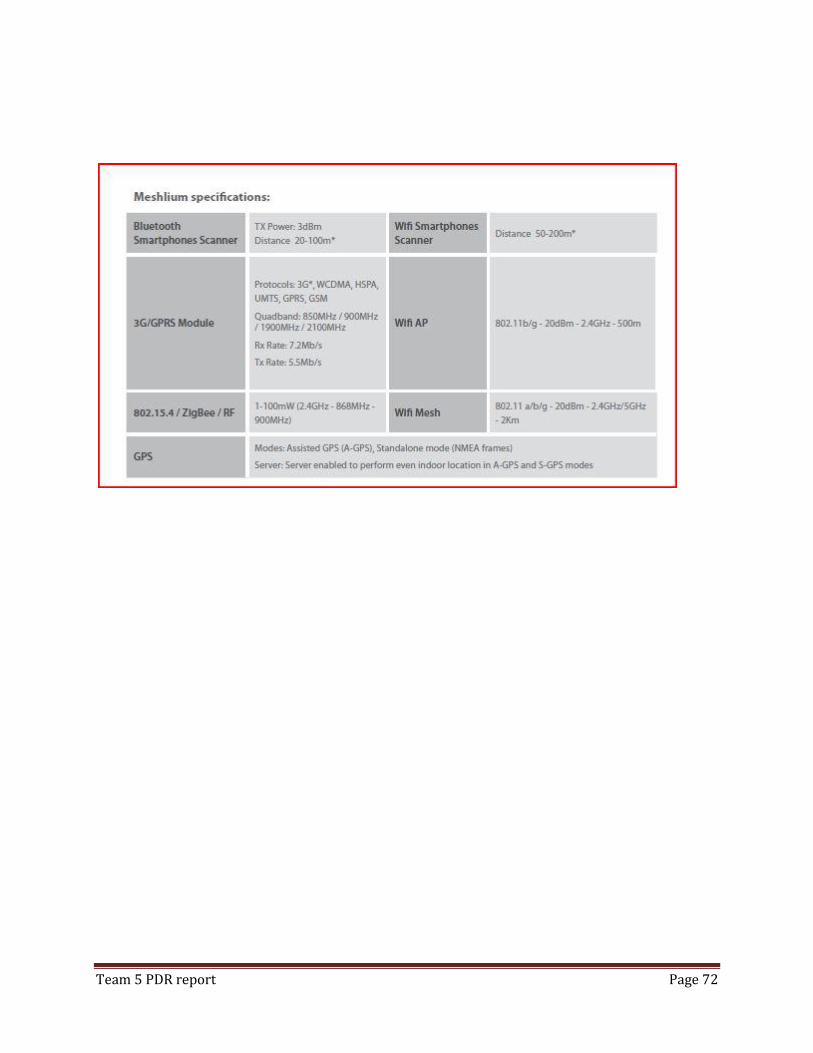
Team 5 PDR report Page 72
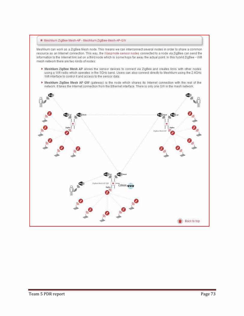
Team 5 PDR report Page 73
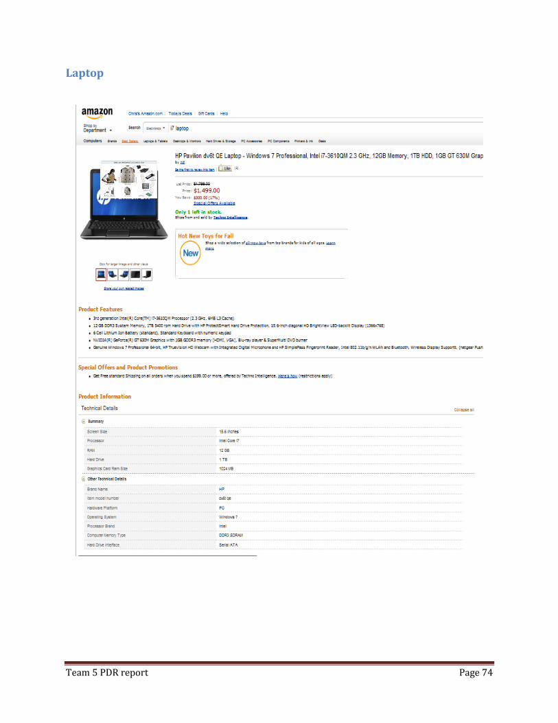
Team 5 PDR report Page 74
Laptop
Team 5 PDR report Page 75
Appendix E: Vendor Communications
Meshlium product query mail set:
All right, Gareth.
Regarding your inquiry, you are right, Meshlium can communicate with all devices
with the same communication protocol, even more if they are also XBee from Digi
like yours.
Then, I'll be waiting for your news.
Kind regards,
Ruben Solano
Sales Engineer
Tlf: +34 976 54 74 92
http://www.libelium.com
Este mensaje, y en su caso, cualquier fichero anexo al mismo, puede
contener información confidencial o legalmente protegida, siendo para
uso exclusivo del destinatario. No hay renuncia a la confidencialidad o
secreto profesional por cualquier transmisión defectuosa o errónea, y
queda expresamente prohibida su divulgación, copia o distribución a
terceros sin la autorización expresa de Libelium. Si ha recibido este
mensaje por error, se ruega lo notifique a Libelium enviando un mensaje
al remitente o al correo electrónico [email protected] y proceda
inmediatamente al borrado del mensaje original y de todas sus copias.
Gracias por su colaboración.
This message and any files sent herewith may contain confidential or
legally protected Information, and are only intended for the eyes of
the addressee. Reception by any other than the intended recipient does
not waive Libelium's legal protection rights, and it is forbidden to
report on, copy or deliver the information to third parties without
Libelium's prior consent. Should you receive this communication by
mistake, please immediately delete the original message and all the
existing copies from your system and report to [email protected] or
reply to sender. Thank you for your cooperation.
El 09/10/12 13:20, Caunt, Gareth H. (S&T-Student) escribió:
Dear Ruben,

Team 5 PDR report Page 76
Thank you for the information in your reply.
May I share the information you have provided with the rest of my team? At the moment, we are undertaking a design project that is successful will be implemented next year.
The university has developed it's own Motes (https://sites.google.com/a/mst.edu/missouri-snt-motes/motes-brief-factsheet) so we are hoping to integrate the Meshlium capabilities with those
mote devices. Has the Meshlium been tested to work with motes other than the WaspMote? From what I see on your website, the majority of the API's are openly available. Is there
anything in the Meshlium to WaspMote communications that would prevent us from writing code
to integrate the university motes?
Kind regards,
Gareth Caunt
From: Ruben Solano [[email protected]]
Sent: Tuesday, 9 October 2012 9:51 PM To: Caunt, Gareth H. (S&T-Student)
Subject: Re: [Libelium : Meshlium : info]
Dear Gareth,
My name is Ruben Solano and I am Sales Engineer for Libelium.
Firstly I would like to appreciate your interest in our products.
Secondly regarding your inquiry about interfacing 802.15.4-ZigBee, let
me say that it is completely possible using our technology. Your motes
would have to be compound of:
Wasmote board with 802.15.4 Expansion board ZigBee communication module Battery
Team 5 PDR report Page 77
And regarding the availability to the US, you could have there the merchandise
within 10 business days.
Please find attached the prices catalog with all available modules and
configurations at:
http://www.libelium.com/xhjs76gd/libelium_products_catalogue_usa.pdf
I suggest visiting our support and development areas, where we give
all the information to help making an easy and powerful development.
And also please take a look to Meshlium:
http://www.libelium.com/products/meshlium
It interconnects up to 6 different technologies, acting as a 'hub router':
WiFi, WSN (ZigBee / 802.15.4), GPRS, Bluetooth, Ethernet and GPS. It is not
necessary in Waspmote networks, but it is very useful because it helps routing
the info. It can also create VPNs (virtual private networks) to provide connection
in any scenario.
If you needed a formal proposal you could send me an email or fill out the
order form in:
http://www.libelium.com/order_form
Please do not hesitate to contact me if you have any further questions.
I am looking forward to hearing from you.
Best regards,
Ruben Solano
Sales Engineer
Tlf: +34 976 54 74 92
http://www.libelium.com
Este mensaje, y en su caso, cualquier fichero anexo al mismo, puede
contener información confidencial o legalmente protegida, siendo para
uso exclusivo del destinatario. No hay renuncia a la confidencialidad o
secreto profesional por cualquier transmisión defectuosa o errónea, y

Team 5 PDR report Page 78
queda expresamente prohibida su divulgación, copia o distribución a
terceros sin la autorización expresa de Libelium. Si ha recibido este
mensaje por error, se ruega lo notifique a Libelium enviando un mensaje
al remitente o al correo electrónico [email protected] y proceda
inmediatamente al borrado del mensaje original y de todas sus copias.
Gracias por su colaboración.
This message and any files sent herewith may contain confidential or
legally protected Information, and are only intended for the eyes of
the addressee. Reception by any other than the intended recipient does
not waive Libelium's legal protection rights, and it is forbidden to
report on, copy or deliver the information to third parties without
Libelium's prior consent. Should you receive this communication by
mistake, please immediately delete the original message and all the
existing copies from your system and report to [email protected] or
reply to sender. Thank you for your cooperation.
El 08/10/12 01:21, [email protected] escribió:
Producto: Meshlium
Asunto: info
Nombre: Gareth Caunt
Empresa: Missouri Science and Technolog
URL:
E-mail: [email protected]
Pais: Australia
-----------------------------------------------------------------
Nos ha conocido por: buscadores
Texto: Hi,
I am a student at Missouri Science and Technology and we are doing a
project that requires interfacing to an Zigbee/802.15.4 sensor array.
Our part is to store the information and process the stored data to
display to an operator.
I found your product via google search and for our project need
pricing and availability in the USA. It would also assist if I could
get some information on the MTBF anf MTTR of the Meshlium.
For the project we have been looking at a mesh of routers connecting
to the Zigbee/802.15.4 sensors feeding back to a central control room.
Power over ethernet is preferred to minimize the need to run cables and
remove the need for an electrician for installation work.
Any help you can provide would be appreciated,
Kind regards,
Gareth Caunt