Embed Size (px)
Citation preview
Journal of Nuclear Materials 335 (2004) 232–238
www.elsevier.com/locate/jnucmat
Preliminary results of post-irradiation examinationson LiSoR-2 test section
Y. Dai *, H. Glasbrenner, V. Boutellier, R. Bruetsch, X. Jia, F. Groeschel
Paul Scherrer Institut, 5232 Villigen PSI, Switzerland
Abstract
Liquid–solid reaction under irradiation (LiSoR) experiments are aimed at understanding the effects of liquid lead–
bismuth eutectic (LBE) corrosion and embrittlement under irradiation on structural materials, which is one of the key
items of the materials R&D for the future accelerator-driven system (ADS). The LiSoR setup is basically a LBE loop
with a test section irradiated with 72 MeV protons. The second irradiation was conducted for about 34 h and termi-
nated after a leakage of LBE was detected. Post-irradiation examinations (PIE) are being performed on both the tube
and tensile specimen in the test section. Optical microscopy, scanning electron microscopy, transmission electron micro-
scopy and microhardness tests have been completed. The results show that a crack formed in the irradiation zone of
the tube. In the material in the irradiation zones of both the tube and the tensile specimen dislocation cell structure
is well developed, which indicates heavy deformation due to thermal fatigue. The crack should start at the inner surface
and propagate to the outer surface. The fracture surfaces of the crack are dominated by a brittle cleavage fracture
mode. However, on the surfaces of the tensile specimen, no microcracks are observed.
� 2004 Elsevier B.V. All rights reserved.
1. Introduction
Liquid lead–bismuth eutectic (LBE) has been consid-
ered as both the coolant in the core and the target mate-
rial in the spallation target of a future accelerator-driven
system (ADS) for transmutation of nuclear waste [1,2].
One of critical issues for operating an ADS device is re-
lated to the structural materials used in the heavy irradi-
ation areas such as the target and the core. The
structural materials in the target, particularly those at
the proton beam window, will be exposed to intensive
0022-3115/$ - see front matter � 2004 Elsevier B.V. All rights reserv
doi:10.1016/j.jnucmat.2004.07.026
* Corresponding author. Tel.: +41 56 310 4171; fax: +41 56
310 4529.
E-mail address: [email protected] (Y. Dai).
irradiation in the presence of relatively high mechanical
loads, while LBE corrosion and embrittlement effects
cannot be excluded. To understand the behavior of the
structural materials used in the target is of essential
importance for a safe operation of the system.
For developing such an ADS device, an international
project, MEGAPIE – 1 Megawatt Pilot Experiment, was
launched to demonstrate the feasibility of operating a
liquid metal target by using the existing spallation neu-
tron facility (SINQ) at PSI [3,4]. In the MEGAPIE tar-
get, LBE will be used as the target material and
martensitic steel T91, one of candidate structural mate-
rials for the ADS, will be used for the LBE container.
Therefore, to the MEGAPIE project and also the mate-
rials technology of the ADS program, it is important to
study the properties of T91 in an irradiation and LBE
corrosion environment.
ed.
Y. Dai et al. / Journal of Nuclear Materials 335 (2004) 232–238 233
LiSoR experiments were proposed for investigating
the behavior of materials in liquid metals under the irra-
diation of 72 MeV protons produced by Injector-I at the
Paul Scherrer Institut (PSI), Switzerland [5]. Preliminary
neutronic calculations indicated that the irradiation of
72 MeV protons could closely simulate that of 600
MeV protons in terms of radiation damage rate, helium,
hydrogen and other transmutation elements production.
With collaboration between PSI and Subatech, France,
a LBE loop has been set up [6]. The test section of the
loop consists of a tube and a tensile specimen. The spec-
imen is stressed in tension to a mechanical load of 200
MPa during irradiation to simulate the effects of the
mechanical load and irradiation at the beam window
of the MEGAPIE target. The second irradiation was
conducted for about 34 h and terminated after a leakage
was detected [7]. In this experiment, the irradiation zone
of the tube in the test section was overheated due to
wobbling beam at a too low of frequency. The material
in the irradiated area was deformed by thermal fatigue.
Finally a crack developed and resulted in the leakage.
The post-irradiation examinations (PIE) are being per-
formed on both the tube and tensile specimen. The pre-
sent paper will show results of the visual inspections and
scanning electron microscopy (SEM) and transmission
electron microscopy (TEM) investigations.
2. Experimental
2.1. Material and specimens
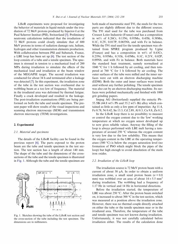
The details of the LiSoR facility can be found in the
previous report [6]. The parts exposed to the proton
beam are the tube and tensile specimen in the test sec-
tion. The test section has a length of about 140 mm.
The shape of the tube and the dimensions of the cross-
sections of the tube and the tensile specimen is illustrated
in Fig. 1. Although the tube and the tensile specimen are
Fig. 1. Sketches showing the tube of the LiSoR test section and
the cross-section of the tube including the test specimen. The
dimensions are in millimeters.
both made of martensitic steel T91, the steels for the two
parts are slightly different due to the different sources.
The T91 steel used for the tube was purchased from
Creusot Loire Industrie (France) and has a composition
in wt% of 8.26Cr, 0.13Ni, 0.95Mo, 0.43Si, 0.38Mn,
0.1C, 0.2V, 0.017P, 0.065Nb, and with Fe in balance.
While the T91 steel used for the tensile specimen was ob-
tained from SPIRE program produced by Ugine
(France) and has a composition in wt% of 8.63Cr,
0.23Ni, 0.95Mo, 0.31Si, 0.43Mn, 0.1C, 0.21V, 0.02P,
0.09Nb, and with Fe in balance. Both materials have
the standard heat treatment, namely normalized at
1040 �C for 1 h followed by air cooling, and then tem-pered at 760 �C for 1 h followed by air cooling. The
outer surfaces of the tube were milled and the inner sur-
faces were cut with an electron discharging machine
(EDM). Both the outer and inner surfaces were irradi-
ated without any further polishing. The tensile specimen
was also cut by an electron discharging machine. Its sur-
faces were polished mechanically and finished with 1000
grit grinding papers.
Impag AG (Switzerland) supplied the eutectic Pb–
55.5Bi (44.8 wt% Pb and 55.2 wt% Bi) alloy which con-
tained as little as only a few ppm of impurities: Ag 11.4,
Fe 0.78, Ni 0.42, Sn 13.3, Cd 2.89, Al 0.3, Cu 9.8, Zn 0.2.
In the LiSoR loop there is no possibility to measure
or control the oxygen content due to the �low� workingtemperature at which no oxygen sensor developed up
to now gives reliable values. Anyway the filling of the
loop is always performed with LBE melt having a tem-
perature of around 250 �C whereas the oxygen contentis very low due to the low solubility. This means that
the oxygen content in the LBE at the operating temper-
ature (300 �C) is below the oxygen saturation level (no
formation of PbO which might block the pipes of the
loop) but high enough to avoid dissolution of the steels
iron oxides.
2.2. Irradiation of the LiSoR loop
The irradiation source is 72 MeV proton beam with a
current of about 50 lA. In order to obtain a uniformirradiation zone, a small sized proton beam (r = 0.8mm) was wobbled over an area of about 14 · 5.5 mm2
during irradiation. The wobbling had a frequency of
1.17 Hz in vertical and 14 Hz in horizontal directions.
Before the irradiation started, the temperature of
LBE was about 250 �C. After the proton beam switched
on, it increased to about 300 �C in the test section, whichwas measured at a position above the irradiation zone.
However, there was no thermal couple directly attached
on either the tube or the tensile specimen near or in the
irradiated area. Therefore, the temperature of the tube
and tensile specimen was not known during irradiation.
Unfortunately, it was not carefully calculated before
irradiation either. The results of the calculation done
234 Y. Dai et al. / Journal of Nuclear Materials 335 (2004) 232–238
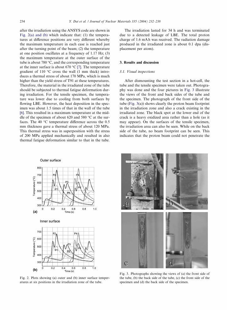
after the irradiation using the ANSYS code are shown in
Fig. 2(a) and (b) which indicate that: (1) the tempera-
tures at difference positions are very different whereby
the maximum temperature in each case is reached just
after the turning point of the beam; (2) the temperature
at one position oscillates at a frequency of 1.17 Hz; (3)
the maximum temperature at the outer surface of the
tube is about 780 �C, and the corresponding temperatureat the inner surface is about 670 �C [7]. The temperaturegradient of 110 �C cross the wall (1 mm thick) intro-
duces a thermal stress of about 170 MPa, which is much
higher than the yield stress of T91 at these temperatures.
Therefore, the material in the irradiated zone of the tube
should be subjected to thermal fatigue deformation dur-
ing irradiation. For the tensile specimen, the tempera-
ture was lower due to cooling from both surfaces by
flowing LBE. However, the heat deposition in the spec-
imen was about 1.5 times of that in the wall of the tube
[6]. This resulted in a maximum temperature at the mid-
dle of the specimen of about 620 and 580 �C at the sur-faces. The 40 �C temperature difference across the 0.5
mm thickness gave a thermal stress of about 120 MPa.
This thermal stress was in superposition with the stress
of 200 MPa applied mechanically and resulted in also
thermal fatigue deformation similar to that in the tube.
Fig. 2. Plots showing (a) outer and (b) inner surface temper-
atures at six positions in the irradiation zone of the tube.
The irradiation lasted for 34 h and was terminated
due to a detected leakage of LBE. The total proton
charge of 1.6 mAh was received. The radiation damage
produced in the irradiated zone is about 0.1 dpa (dis-
placement per atom).
3. Results and discussion
3.1. Visual inspections
After dismounting the test section in a hot-cell, the
tube and the tensile specimen were taken out. Photogra-
phy was done and the four pictures in Fig. 3 illustrate
the views of the front and back sides of the tube and
the specimen. The photograph of the front side of the
tube (Fig. 3(a)) shows clearly the proton beam footprint
in the irradiation zone and also a crack existing in the
irradiated zone. The black spot at the lower end of the
crack is a heavy oxidized area rather than a hole (as it
may appear). On the surfaces of the tensile specimen,
the irradiation area can also be seen. While on the back
side of the tube, no beam footprint can be seen. This
indicates that the proton beam could not penetrate the
Fig. 3. Photographs showing the views of (a) the front side of
the tube, (b) the back side of the tube, (c) the front side of the
specimen and (d) the back side of the specimen.
Y. Dai et al. / Journal of Nuclear Materials 335 (2004) 232–238 235
whole test section which is in agreement with neutronics
calculation [6].
On the surfaces of the specimen there is some Pb–Bi
attached in the irradiation area and also in the region
immediate above the irradiation area, where the temper-
ature could be quite high due to the heat brought by the
up-stream LBE. In the large region below the irradiation
area, it looks like something deposited there.
3.2. SEM observations
Systematic SEM observation has been performed to
study the LBE corrosion and irradiation effects on the
tube and specimen.
3.2.1. The inner surface of the tube
Few samples were cut from the upper part of the tube
where the material was not exposed to irradiation. Fig.
4(a) and (b) shows the views of the cross-section and
inner surface away from the exposed region which was
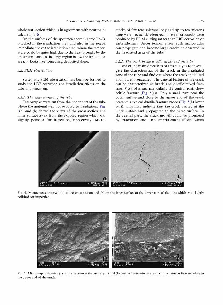
slightly polished for inspection, respectively. Micro-
Fig. 4. Microcracks observed (a) at the cross-section and (b) on the
polished for inspection.
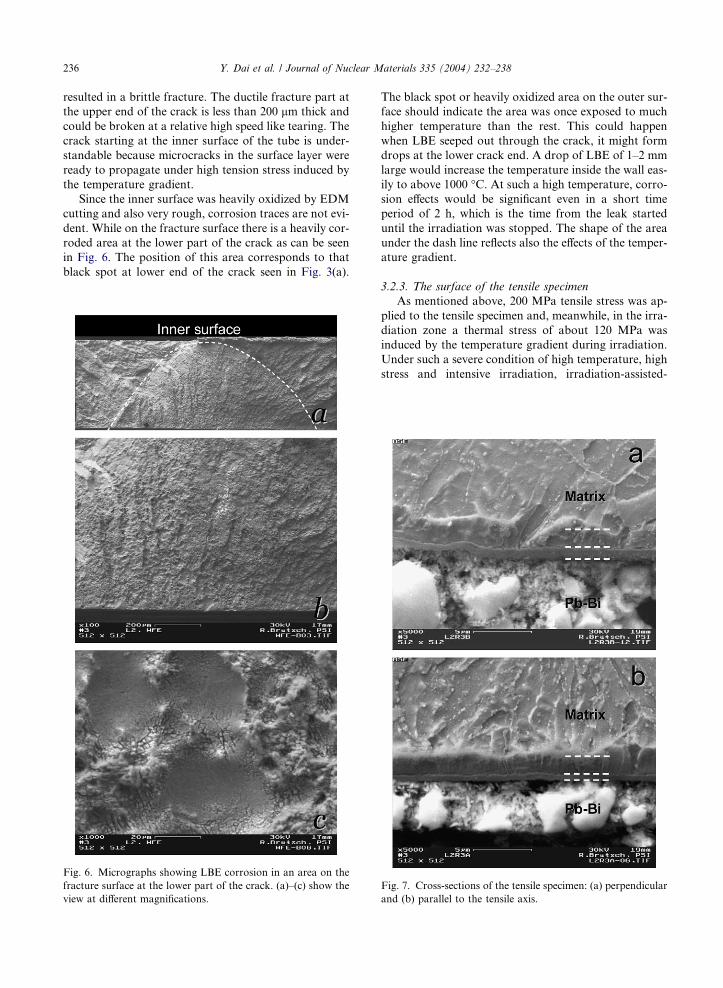
Fig. 5. Micrographs showing (a) brittle fracture in the central part and
the upper end of the crack.
cracks of few tens microns long and up to ten microns
deep were frequently observed. These microcracks were
produced by EDM cutting rather than LBE corrosion or
embrittlement. Under tension stress, such microcracks
can propagate and become large cracks as observed in
the irradiated area of the tube.
3.2.2. The crack in the irradiated zone of the tube
One of the main objectives of this study is to investi-
gate the characteristics of the crack in the irradiated
zone of the tube and find out where the crack initialized
and how it propagated. The general feature of the crack
can be characterized as brittle and ductile mixed frac-
ture. Most of areas, particularly the central part, show
brittle fracture (Fig. 5(a)). Only a small part near the
outer surface and close to the upper end of the crack
presents a typical ductile fracture mode (Fig. 5(b) lower
part). This may indicate that the crack started at the
inner surface and propagated to the outer surface. In
the central part, the crack growth could be promoted
by irradiation and LBE embrittlement effects, which
inner surface at the upper part of the tube which was slightly
(b) ductile fracture in an area near the outer surface and close to
236 Y. Dai et al. / Journal of Nuclear Materials 335 (2004) 232–238
resulted in a brittle fracture. The ductile fracture part at
the upper end of the crack is less than 200 lm thick and
could be broken at a relative high speed like tearing. The
crack starting at the inner surface of the tube is under-
standable because microcracks in the surface layer were
ready to propagate under high tension stress induced by
the temperature gradient.
Since the inner surface was heavily oxidized by EDM
cutting and also very rough, corrosion traces are not evi-
dent. While on the fracture surface there is a heavily cor-
roded area at the lower part of the crack as can be seen
in Fig. 6. The position of this area corresponds to that
black spot at lower end of the crack seen in Fig. 3(a).
Fig. 6. Micrographs showing LBE corrosion in an area on the
fracture surface at the lower part of the crack. (a)–(c) show the
view at different magnifications.
The black spot or heavily oxidized area on the outer sur-
face should indicate the area was once exposed to much
higher temperature than the rest. This could happen
when LBE seeped out through the crack, it might form
drops at the lower crack end. A drop of LBE of 1–2 mm
large would increase the temperature inside the wall eas-
ily to above 1000 �C. At such a high temperature, corro-sion effects would be significant even in a short time
period of 2 h, which is the time from the leak started
until the irradiation was stopped. The shape of the area
under the dash line reflects also the effects of the temper-
ature gradient.
3.2.3. The surface of the tensile specimen
As mentioned above, 200 MPa tensile stress was ap-
plied to the tensile specimen and, meanwhile, in the irra-
diation zone a thermal stress of about 120 MPa was
induced by the temperature gradient during irradiation.
Under such a severe condition of high temperature, high
stress and intensive irradiation, irradiation-assisted-
Fig. 7. Cross-sections of the tensile specimen: (a) perpendicular
and (b) parallel to the tensile axis.
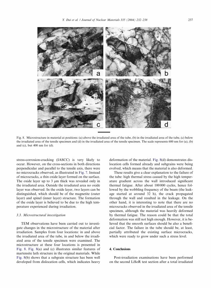
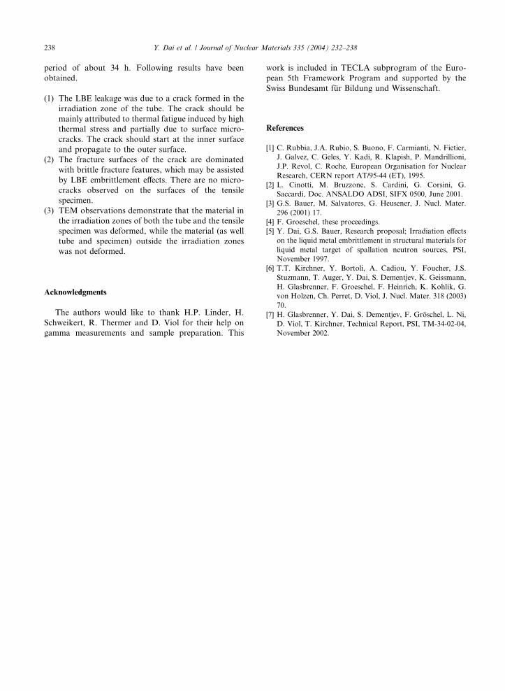
Fig. 8. Microstructure in material at positions: (a) above the irradiated area of the tube, (b) in the irradiated area of the tube, (c) below
the irradiated area of the tensile specimen and (d) in the irradiated area of the tensile specimen. The scale represents 600 nm for (a), (b)
and (c), but 400 nm for (d).
Y. Dai et al. / Journal of Nuclear Materials 335 (2004) 232–238 237
stress-corrosion-cracking (IASCC) is very likely to
occur. However, on the cross-sections in both directions
perpendicular and parallel to the tensile axis, there were
no microcracks observed, as illustrated in Fig. 7. Instead
of microcracks, a thin oxide layer formed on the surface.
The oxide layer up to 3 lm thick was revealed only in
the irradiated area. Outside the irradiated area no oxide
layer was observed. In the oxide layer, two layers can be
distinguished, which should be of the magnetite (outer
layer) and spinel (inner layer) structure. The formation
of the oxide layer is believed to be due to the high tem-
perature experienced during irradiation.
3.3. Microstructural investigation
TEM observations have been carried out to investi-
gate changes in the microstructure of the material after
irradiation. Samples from four locations: in and above
the irradiated area of the tube, in and below the irradi-
ated area of the tensile specimen were examined. The
microstructure at these four locations is presented in
Fig. 8. Fig. 8(a) and (c) illustrates similar features of
martensite lath structure in the original materials. While
Fig. 8(b) shows that a subgrain structure has been well
developed from dislocation cells, which indicates heavy
deformation of the material. Fig. 8(d) demonstrates dis-
location cells formed already and subgrains were being
evolved, which means that the material is also deformed.
These results give a clear explanation to the failure of
the tube: high thermal stress caused by the high temper-
ature gradient across the wall introduced significant
thermal fatigue. After about 100000 cycles, hence fol-
lowed by the wobbling frequency of the beam (the leak-
age started at around 32 h), the crack propagated
through the wall and resulted in the leakage. On the
other hand, it is interesting to note that there are no
microcracks observed in the irradiated area of the tensile
specimen, although the material was heavily deformed
by thermal fatigue. The reason could be that the total
deformation was still not high enough. However, it is be-
lieved that the smooth surfaces should be also a benefi-
cial factor. The failure in the tube should be, at least,
partially attributed the existing surface microcracks,
which were ready to grow under such a stress level.
4. Conclusions
Post-irradiation examinations have been performed
on the second LiSoR test section after a total irradiated
238 Y. Dai et al. / Journal of Nuclear Materials 335 (2004) 232–238
period of about 34 h. Following results have been
obtained.
(1) The LBE leakage was due to a crack formed in the
irradiation zone of the tube. The crack should be
mainly attributed to thermal fatigue induced by high
thermal stress and partially due to surface micro-
cracks. The crack should start at the inner surface
and propagate to the outer surface.
(2) The fracture surfaces of the crack are dominated
with brittle fracture features, which may be assisted
by LBE embrittlement effects. There are no micro-
cracks observed on the surfaces of the tensile
specimen.
(3) TEM observations demonstrate that the material in
the irradiation zones of both the tube and the tensile
specimen was deformed, while the material (as well
tube and specimen) outside the irradiation zones
was not deformed.
Acknowledgments
The authors would like to thank H.P. Linder, H.
Schweikert, R. Thermer and D. Viol for their help on
gamma measurements and sample preparation. This
work is included in TECLA subprogram of the Euro-
pean 5th Framework Program and supported by the
Swiss Bundesamt fur Bildung und Wissenschaft.
References
[1] C. Rubbia, J.A. Rubio, S. Buono, F. Carmianti, N. Fietier,
J. Galvez, C. Geles, Y. Kadi, R. Klapish, P. Mandrillioni,
J.P. Revol, C. Roche, European Organisation for Nuclear
Research, CERN report AT/95-44 (ET), 1995.
[2] L. Cinotti, M. Bruzzone, S. Cardini, G. Corsini, G.
Saccardi, Doc. ANSALDO ADSI, SIFX 0500, June 2001.
[3] G.S. Bauer, M. Salvatores, G. Heusener, J. Nucl. Mater.
296 (2001) 17.
[4] F. Groeschel, these proceedings.
[5] Y. Dai, G.S. Bauer, Research proposal; Irradiation effects
on the liquid metal embrittlement in structural materials for
liquid metal target of spallation neutron sources, PSI,
November 1997.
[6] T.T. Kirchner, Y. Bortoli, A. Cadiou, Y. Foucher, J.S.
Stuzmann, T. Auger, Y. Dai, S. Dementjev, K. Geissmann,
H. Glasbrenner, F. Groeschel, F. Heinrich, K. Kohlik, G.
von Holzen, Ch. Perret, D. Viol, J. Nucl. Mater. 318 (2003)
70.
[7] H. Glasbrenner, Y. Dai, S. Dementjev, F. Groschel, L. Ni,
D. Viol, T. Kirchner, Technical Report, PSI, TM-34-02-04,
November 2002.