Embed Size (px)
Citation preview

Premier Alarm Sounder Backplates
Flashguard - The Installer’s Choice
GB 1 - 5
InstallationInstructions
E 6 - 10
Instrucciones deInstalación
ENG & SPANISH LEAFLET 3/7/06 9:57 AM Page 2
PCB
BATTERY
SO
UN
DE
R
BATTERY
ON OFF
WARNING - HIGH VOLTAGE
TRIM OUTERINSULATIONHERE
TRIM INNERWIRES TOHERE
A
C
A
B
D
A
AA
D
D
D D
D D
FE
J
I
Piezo
Piezo
I
Battery8.4V 280mAh
D
A
PiezoBattery8.4V 280mAh
D14 D13
WARNINGUSE EAR
PROTECTION TO AVOID
PERSONALINJURY
Piezo
B
+ BELL MODE
SCB SAB
TAMPER MODE
SERIES TAMPER
OFF ON
TONE
SLOW FAST
J2J1
T1
M4
M3
CON3
R4C2
+
+C1
+C6
L1
C7
T2
X1
D7
STROBE+VE
TRIGGER+VE
TRIGGER-VE
STROBE-VE
SUPPLY+VE
SUPPLY-VE
TAMPERRETURNTAMPERSERIES
MICROB
MOCROA
0
1
2
3
4
5
6
7
8
9
10
11
KLAXON SIGNALS LTD42-103588 VER A© 2004
GH
K
L
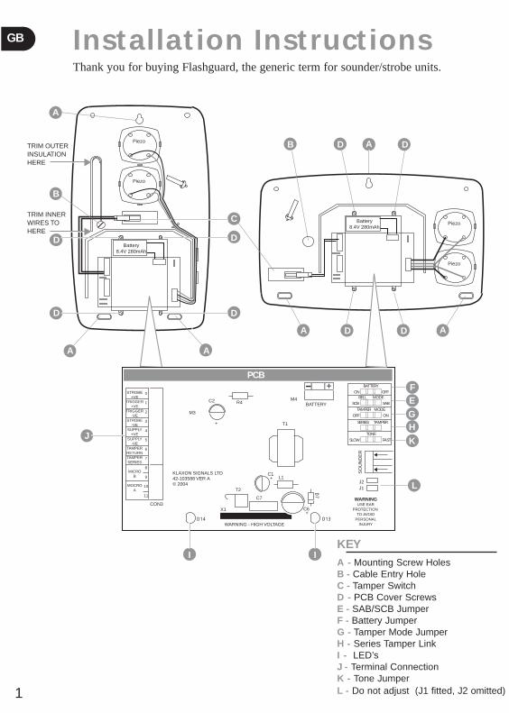
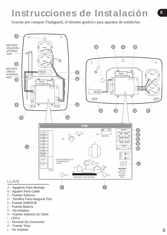
KEYA - Mounting Screw HolesB - Cable Entry HoleC - Tamper SwitchD - PCB Cover ScrewsE - SAB/SCB JumperF - Battery JumperG - Tamper Mode JumperH - Series Tamper Link I - LED’sJ - Terminal ConnectionK - Tone JumperL - Do not adjust (J1 fitted, J2 omitted)
Installation InstructionsThank you for buying Flashguard, the generic term for sounder/strobe units.
1
GB
ENG & SPANISH LEAFLET 3/7/06 9:57 AM Page 3
1 Mounting and Assembly Instructions
● Using the backplate of the unit (or the template on the rear of the carton) mark the positions of the three mounting screw holes (A), and cable entry hole (B).
● Drill and plug the screw holes as marked.
● Using a long masonry drill bit, drill a hole through the wall for the cable.
● Pass the cable through the grommet in the cable entry hole (B) and strip the cable using the guide on the backplate. Mount the unit to the wall using the three screws provided.
● Make the required connections to the terminal block as described in sections 3 and 4.
● Configure the jumpers as described in section 2.
● Replace the lid and tighten screw.
2 Jumper ConfigurationBattery (BATT) (F)Once installed, this jumper must be moved to the ON position to connect the battery. This will activate the automatic 5 second sound test. The LED’s will not illuminate until the hold-off voltage is applied.
SAB / SCB Operation (E)Move the jumper to SCB position to minimise the current drawn from the control panel. A reduction in sound level occurs in SCB mode.
Tamper Mode (G)This jumper controls the behaviour of the sounder when the tamper switch is opened.
ON The siren will self-activate when the switch is opened in accordance with BS4737
OFF The siren will not self-activate but will still open the tamper loop tothe panel. Activation off the sounder on ‘bell tamper’ is controlled by the panel.
Series Tamper (H)
This link must be cut when the tamper loops of two sounders are connected in series to the same control panel
Tone (K)
By moving this jumper the tone of the sounder can be altered. This featurecan be used to distinguish two sounders mounted in close proximity.
3 Cut Off Timer
The sounder has a fixed 15 minute cut off timer
Off On
Tamp Mode
On
Slow Fast
Batt
Off
SCB SAB
Tone
SeriesTamper
2
GB
ENG & SPANISH LEAFLET 3/7/06 9:57 AM Page 4
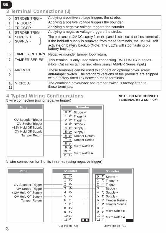
3 Terminal Connections (J)
4 Typical Wiring Configurations5 wire connection (using negative trigger)
5 wire connection for 2 units in series (using negative trigger)
0 STROBE TRIG + 1 TRIGGER +2 TRIGGER - 3 STROBE TRIG - 4 SUPPLY +5 SUPPLY -
6 TAMPER RETURN
7 TAMPER SERIES
8 MICRO B9
10 MICRO A11
OV Sounder TriggerOV Strobe Trigger
+12V Hold Off SupplyOV Hold Off Supply
Tamper Return
Panel0123456789
1011
Strobe +Trigger +Trigger -Strobe -Supply +Supply -Tamper ReturnTamper Series
Microswitch B
Microswitch A
Sounder
Cut link on PCB Leave link on PCB
}
Panel
01234567891011
Strobe +Trigger +Trigger -Strobe -Supply +Supply -Tamper ReturnTamper Series
Microswitch B
Microswitch A
SounderSounder
OV Sounder TriggerOV Strobe Trigger
+12V Hold Off SupplyOV Hold Off Supply
Tamper Return
3
GB
Applying a positive voltage triggers the strobe.Applying a positive voltage triggers the sounder.Applying a negative voltage triggers the sounder.Applying a negative voltage triggers the strobe.The permanent 12V DC supply from the panel is connected to these terminals.If the hold-off supply is removed from these terminals, the unit will selfactivate on battery backup (Note: The LED’s will stop flashing on battery backup.)
Negative sounder tamper loop return.
This terminal is only used when connecting TWO UNITS in series.(Note: Cut series tamper link when using TAMPER Series input.)
These terminals can be used to connect an optional cover screwanti-tamper switch. The standard versions of the products are shippedwith a factory fitted link between these terminals.The combined cover/back anti-tamper switch is factory fitted tothese terminals.
NOTE: DO NOT CONNECTTERMINAL 0 TO SUPPLY+
01234567891011
ENG & SPANISH LEAFLET 3/7/06 9:57 AM Page 5

5 Precautions
● Two units in series
Note: In this configuration the total current consumption approaches 1 amp. Ensure that the alarm panel can source this amount of current. If in doubt change the mode of operation of one or both units to SCB to reduce the current load on the panel.
● Tamper switches (C)
Care should be taken to ensure that none of the wiring prevents the tamper switch from moving freely.
● Battery replacement
Klaxon Signals recommends that the NimH rechargeable battery is replaced every five years.To change the battery, remove the PCB cover by unscrewing the four securing screws (D)and unscrew the battery terminals to release the battery leads. Installation is reverse of the above. Always ensure battery leads are connected to correct polarity terminals.Note: The strobe circuit can retain a stored charge for some time after the power to the circuithas been removed. Care should be taken when handling the PCB.
● Weather proofing
Please ensure that all reasonable precautions are taken to ensure unit remains dry during installation.
Free Screen Printing
You supply the artwork and we will do the rest!
Let us create a professional company image which will heighten your company profile and placean advertisement at every installation.
FREE screen printing is available on orders of more than 30 units. (Any combination of live anddecoy units).
All logos are produced using the latest computer aided design software and then hand printedusing specialised high durability inks.
For further information contact our Customer Services at
Telephone: +44 (0) 161 287 5555Fax: +44 (0) 161 287 5511E-mail: [email protected]
4
GB
ENG & SPANISH LEAFLET 3/7/06 9:57 AM Page 6

Technical Specification Sounders
Maximum Sounder Output (dBA @ 1m) 118Strobe Frequency (Hz) 1
Input Voltage
- Maximum 15- Minimum 10
Current Consumption (mA) @ 13.2V
- Sounder (SAB mode) 320- Sounder (SCB mode) 40- Strobe 120- Standby Current 35- Maximum battery charge current 20
(constant current charger)
5
GB
Technical Helpline & Sales Hotline
● Technical Helpline: +44 (0)161 287 4029 ● Sales Hotline: +44 (0)161 287 5555
ENG & SPANISH LEAFLET 3/7/06 9:57 AM Page 7
Instrucciones de Instalación Gracias por comprar Flashguard, el término genérico para aparatos de sonido/luz.
6
E
PCB
BATTERY
SO
UN
DE
R
BATTERY
ON OFF
WARNING - HIGH VOLTAGE
A
C
A
B
D
A
AA
D
D
D D
D D
FE
J
I I
D
A
Piezo
D14 D13
WARNINGUSE EAR
PROTECTION TO AVOID
PERSONALINJURY
Piezo
B
+ BELL MODE
SCB SAB
TAMPER MODE
SERIES TAMPER
OFF ON
TONE
SLOW FAST
J2J1
T1
M4
M3
CON3
R4C2
+
+C1
+C6
L1
C7
T2
X1
D7
STROBE+VE
TRIGGER+VE
TRIGGER-VE
STROBE-VE
SUPPLY+VE
SUPPLY-VE
TAMPERRETURNTAMPERSERIES
MICROB
MOCROA
0
1
2
3
4
5
6
7
8
9
10
11
KLAXON SIGNALS LTD42-103588 VER A© 2004
GH
K
L
RECORTE AISLACIÓN EXTERNA AQUÍ
RECORTECABLES INTERNOSAQUÍ
Batería8.4V 280mAh
Batería8.4V 280mAh
Piezo
Piezo
LLAVEA - Agujeros Para MontajeB - Agujero Para CableC - Puente SobornoD - Tornillos Para Asegurar PcbE - Puente SAB/SCBF - Puente Batería G - No emplearH - Puente Soborno En SérieI - LED’sJ - Terminal De ConecciónK - Puente TonoL - No emplear
ENG & SPANISH LEAFLET 3/7/06 9:57 AM Page 8
1 Instrucciones de Montaje:
● Usando la placa trasera del aparato (o el molde detrás del cartón) marque las posiciones de los tres agujeros de montaje (A), y el agujero para cable (B).
● Taladre y prepare los agujeros marcados
● Usando un taladro largo, haga un agujero a través de la pared para el cable.
● Pase el cable a través del seguro en el agujero para cable (B) y descubra el cable usandola guía en la placa trasera.
● Asegure el aparato a la pared usando los tres tornillos adjuntos. Haga las conexiones requeridas al terminal de conexión como se describe en secciones 3 y 4
● Use los puentes descritos en la sección 2.
● Cierre y asegure el tornillo.
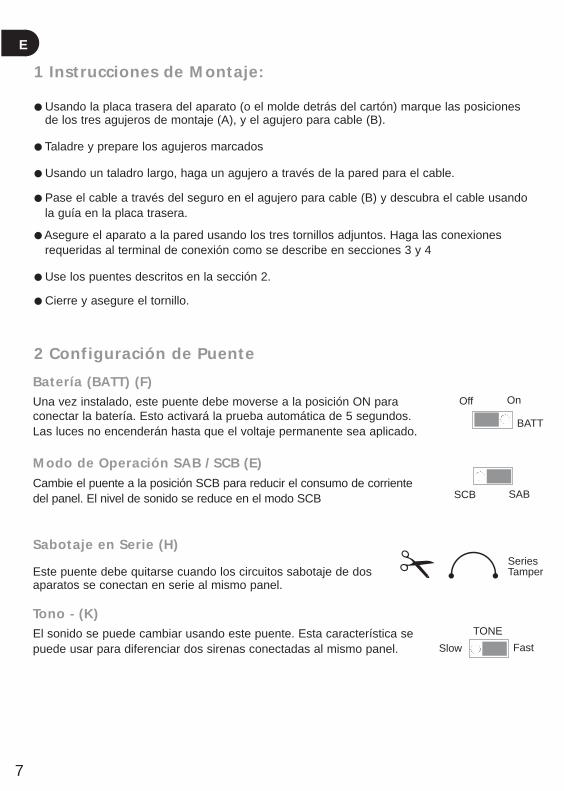
2 Configuración de Puente
Batería (BATT) (F)Una vez instalado, este puente debe moverse a la posición ON paraconectar la batería. Esto activará la prueba automática de 5 segundos.Las luces no encenderán hasta que el voltaje permanente sea aplicado.
Modo de Operación SAB / SCB (E)Cambie el puente a la posición SCB para reducir el consumo de corrientedel panel. El nivel de sonido se reduce en el modo SCB
Sabotaje en Serie (H)
Este puente debe quitarse cuando los circuitos sabotaje de dos aparatos se conectan en serie al mismo panel.
Tono - (K)El sonido se puede cambiar usando este puente. Esta característica sepuede usar para diferenciar dos sirenas conectadas al mismo panel.
Off On
Slow Fast
BATT
SCB SAB
TONE
7
E
SeriesTamper
ENG & SPANISH LEAFLET 3/7/06 9:57 AM Page 9
8
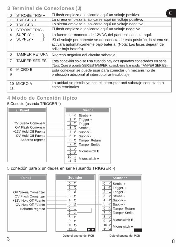
3 Terminal de Conexiones (J)
4 Modo de Conexión típico5 Conecte (usando TRIGGER -)
5 conexión para 2 unidades en serie (usando TRIGGER -)
0 STROBE TRIG + 1 TRIGGER +2 TRIGGER - 3 STROBE TRIG - 4 SUPPLY +5 SUPPLY -
6 TAMPER RETURN
7 TAMPER SERIES
8 MICRO B9
10 MICRO A11
OV Sirena ComenzarOV Flash Comenzar
+12V Hold Off FuenteOV Hold Off Fuente
Soborno regreso
al Panel0123456789
1011
Strobe +Trigger +Trigger -Strobe -Supply +Supply -Tamper ReturnTamper Series
Microswitch B
Microswitch A
Sirena
Quite el puente del PCB Deje el puente del PCB
}
Panel
01234567891011
Strobe +Trigger +Trigger -Strobe -Supply +Supply -Tamper ReturnTamper Series
Microswitch B
Microswitch A
SounderSounder
OV Sirena ComenzarOV Flash Comenzar
+12V Hold Off FuenteOV Hold Off Fuente
Soborno regreso
3
El flash empieza al aplicarse aquí un voltaje positivo.La sirena empieza al aplicarse aquí un voltaje positivo.La sirena empieza al aplicarse aquí un voltaje negativo.El flash empieza al aplicarse aquí un voltaje negativo.
La fuente permanente de 12VDC del panel se conecta aquí.ISi el voltaje permanente se desconecta de esta posición, la sirena se activara automáticamente bajo batería. (Nota: Las luces dejaran de brillar bajo batería).
Regreso negativo del circuito sabotaje.
Esta conexión solo se usa cuando hay dos aparatos conectados en serie.(Nota: Quite el puente SERIES TAMPER cuando use la entrada TAMPER SERIES).Esta conexión se puede usar para conectar un mecanismo de protección adicional al interruptor anti-sabotaje.
La unidad se distribuye con el interruptor anti-sabotaje conectado a estos terminales.
01234567891011
E
ENG & SPANISH LEAFLET 3/7/06 9:57 AM Page 10
5 Precauciones
● Dos sirenas en serie:
Nota: De esta manera el consumo total de corriente se acerca a 1 Amperio. Asegurase de que el Panel de Control puede suplir esta corriente. Si no esta seguro, cambie el modo de operación de una o ambas unidades a SCB para reducir la carga al panel.
● Interruptor sabotaje(C):
Tenga cuidado de asegurar que ningún cable prevenga el libre movimiento del interruptor sabotaje
● Cambio de batería:
Cambio de batería: Klaxon Signals recomienda que la batería recargable NimH sea remplazada cada cinco anos. Para cambiar la batería, afloje los cuatro tornillos (D) y quite la cubierta del PCB, afloje los terminales de la batería para soltar sus cables. La instalación es lo mismo pero al revés. Asegúrese que la polaridad sea la correcta. Nota: El circuito de Flash puede retener carga eléctrica por mucho tiempo después de haberse desconectado. Debe tenerse mucho cuidado al manejar este PCB.
● A Prueba de intemperie: Asegúrese que precauciones adecuadas se han tomado para mantener el aparatoseco durante su instalación.
Estampado
Usted entrega el diseño y nosotros hacemos el resto!
Déjenos crear su estampa profesional que elevara la Imagen de su compañía y pondrá un anuncio en cada instalación
Todos los logotipos se producen usando lo ultimo en programas CAD y luego son pintados amano usando tintas especiales de alta durabilidad.
Para su mayor información contacte a nuestro servicio al cliente en:
PROJECT ADVANCED SECURITY SYSTEMS, S.A.Avda. Doctor Severo Ochoa Nº 35, Edificio 5, Local A 28100 Alcobendas (MADRID)
Tlfno: 91 304 56 43
Fax: 91 754 36 50
e-mail: [email protected]
9
E
ENG & SPANISH LEAFLET 3/7/06 9:57 AM Page 11
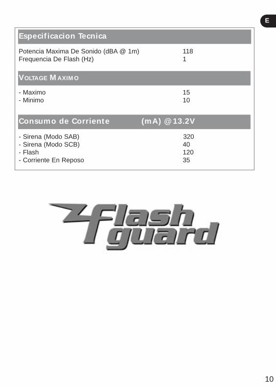
Especificacion Tecnica
Potencia Maxima De Sonido (dBA @ 1m) 118Frequencia De Flash (Hz) 1
VOLTAGE MAXIMO
- Maximo 15- Minimo 10
Consumo de Corriente (mA) @ 13.2V
- Sirena (Modo SAB) 320- Sirena (Modo SCB) 40- Flash 120- Corriente En Reposo 35
10
E
ENG & SPANISH LEAFLET 3/7/06 9:57 AM Page 12

All information on this sheet is believed to be correct at the time of going to press.Klaxon can accept no responsibility for damage caused by incorrect installation.
42-1
03 4
60/5
GB
E
Klaxon Signals LtdWrigley Street,Oldham,LancashireOL4 1HW
Technical Helpline: +44 (0)161 287 4029 Sales Hotline: +44 (0)161 287 5555Fax: +44 (0)161 287 5511Email: [email protected]
Project Advanced Security Systems, S.A.Avda. Doctor Severo Ochoa Nº 35, Edificio 5, Local A 28100 Alcobendas (MADRID)
Tlfno: 91 304 56 43Fax: 91 754 36 50Email: [email protected]
ENG & SPANISH LEAFLET 3/7/06 9:57 AM Page 1