Embed Size (px)
Citation preview
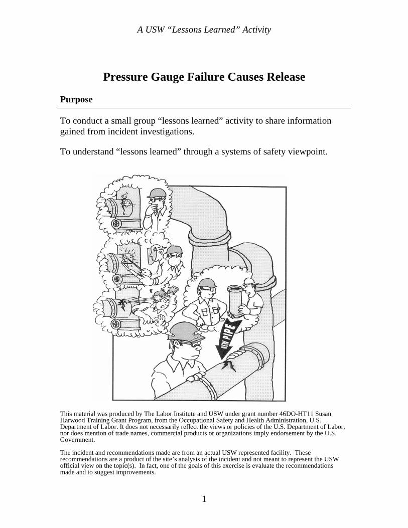
Pressure Gauge Failure Causes Release
Lessons Learned
Volume 04 Issue 02
© 2004 USW
A USW “Lessons Learned” Activity
Pressure Gauge Failure Causes Release Purpose To conduct a small group “lessons learned” activity to share information gained from incident investigations. To understand “lessons learned” through a systems of safety viewpoint.
This material was produced by The Labor Institute and USW under grant number 46DO-HT11 Susan Harwood Training Grant Program, from the Occupational Safety and Health Administration, U.S. Department of Labor. It does not necessarily reflect the views or policies of the U.S. Department of Labor, nor does mention of trade names, commercial products or organizations imply endorsement by the U.S. Government. The incident and recommendations made are from an actual USW represented facility. These recommendations are a product of the site’s analysis of the incident and not meant to represent the USW official view on the topic(s). In fact, one of the goals of this exercise is evaluate the recommendations made and to suggest improvements.
1
A USW “Lessons Learned” Activity
Introduction One Hour “Lessons Learned” Safety Training Activity This is a Small Group Activity Method (SGAM) exercise. It is designed for use in toolbox style meetings where a group of craft persons, operators, or other small group is assembled for a safety training session. The whole group should be further divided into smaller discussion groups of four to six people. The tone of the meetings should be informal to create as much discussion as possible within the groups and among the groups. Active participation by group members is essential for this exercise to be successful. If you plan to present a Lessons Learned Activity and have not been trained in the USW worker trainer program, you should contact the USW Health, Safety & Environment Department: Phone (412) 562-2581 email: [email protected] for trainer information. For this exercise, each person in the group should have their own copy of this activity printed in its entirety. The exercise consists of three tasks. Each task is designed to provoke thought and generate discussion about the incident at hand. Each discussion group should designate a scribe to keep notes and report back to the facilitator and class after each task. When the exercise is completed, review the Summary on page 13. Definitions of terms used in this exercise are provided throughout the activity. A glossary of terms is also provided in the appendix. The incident(s) depicted in this activity are based upon real occurrences. The names of persons and corporations are fictitious.
2
A USW “Lessons Learned” Activity
Task 1 Please read the following scenario: During morning rounds immediately after shift change an operator found a discharge pressure gauge on a recycle isobutene (R/IC4) feed pump had ruptured and was spraying IC4 into the atmosphere. The gauge reads from 0 to 1000 psig. The operating pressure of this system is 750 to 800 psig. The spare pump was started and the leaking pump was shut down. The suction and discharge valves to the pump were closed because the valve for the leaking gauge was found to be leaking by. Fortunately there was no ignition or personal injury due to exposure to the IC4. An investigation found that the gauge was not rated for the service pressure of the pump. The design calls for a pressure gauge rated for two times the maximum design operating pressure of the system. A 0 to 2000 psig gauge should have been used. The bourdon tube (an internal part of the gauge that flexes with pressure and moves the pointer on the dial face) had cracked, causing the leak. The gauge should have been an oil-filled gauge because it is in a high vibration service. The gauge was also hard piped directly to the pump instead of being mounted remotely and connected with a flexible tube or coiled tubing. A liquid filled gauge is the minimum requirement for this service. On a mechanical flow diagram, the type of gauge needed is designated by a standard code. An example would be PG-1X150. P=Standard 4 ½ inch turret type solid front phenolic case G= ½ inch MNPT bottom connection The dash (-) indicates no fill for the gauge body…F=glycerin fill case 1=Material for socket and tip-element
1=Alloy steel and 316 stainless steel 2=316 stainless steel and 316 stainless steel 3=Brass and phosphor bronze 4=R-monel and K-monel
X-Range multiplier, O=No multiplier, X=base times 10, C=base times 100 150=Range base PSIG It was determined that the operators had no idea what the engineering code for the gauges meant. (Neither do I…Do you?)
3
A USW “Lessons Learned” Activity
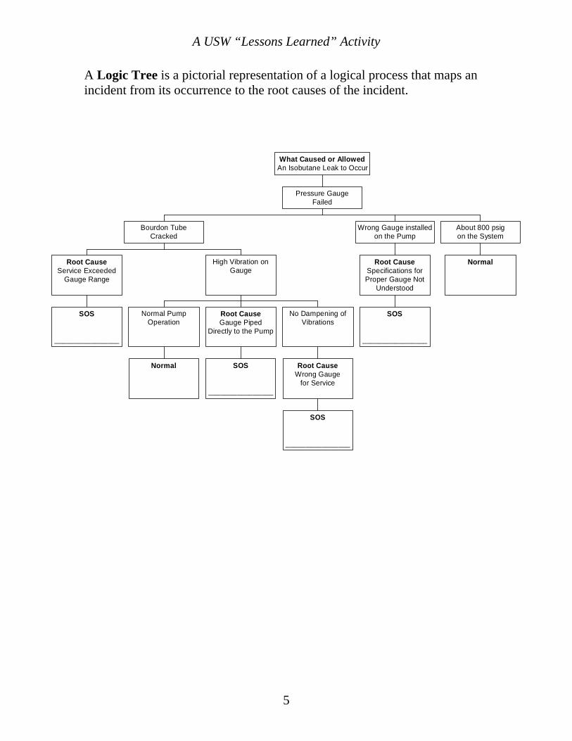
Task 1 (continued) On the next page you will find a logic tree that shows how the investigators at this site linked the incident that occurred (the top event) to the facts described in the scenario and the incident’s root causes. Below each root cause in the logic tree you will find a block with the title “SOS” (System of Safety). Find the boxes marked SOS. Directly above those boxes will be a root cause of the incident. Your task is to complete the logic tree by identifying the major system of safety affected where the root cause failure occurred and list it in the box. These “systems” are listed in a chart on page 9. Note: some of the SOS boxes may already be completed for you. Please select someone in your group to act as scribe to report back your answers.
4
A USW “Lessons Learned” Activity
A Logic Tree is a pictorial representation of a logical process that maps an incident from its occurrence to the root causes of the incident.
SOS
________________
Root CauseService Exceeded
Gauge Range
Normal
Normal PumpOperation
SOS
________________
Root CauseGauge Piped
Directly to the Pump
SOS
________________
Root CauseWrong Gauge
for Service
No Dampening ofVibrations
High Vibration onGauge
Bourdon TubeCracked
SOS
________________
Root CauseSpecifications forProper Gauge Not
Understood
Wrong Gauge installedon the Pump
Normal
About 800 psigon the System
Pressure GaugeFailed
What Caused or AllowedAn Isobutane Leak to Occur
5
A USW “Lessons Learned” Activity
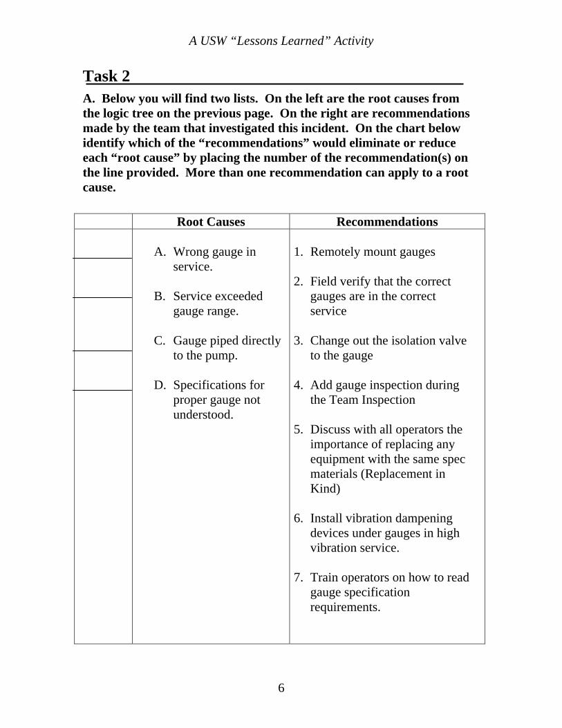
Task 2
A. Below you will find two lists. On the left are the root causes from the logic tree on the previous page. On the right are recommendations made by the team that investigated this incident. On the chart below identify which of the “recommendations” would eliminate or reduce each “root cause” by placing the number of the recommendation(s) on the line provided. More than one recommendation can apply to a root cause.
Root Causes Recommendations
A. Wrong gauge in service.
B. Service exceeded
gauge range.
C. Gauge piped directly to the pump.
D. Specifications for
proper gauge not understood.
1. Remotely mount gauges 2. Field verify that the correct
gauges are in the correct service
3. Change out the isolation valve
to the gauge 4. Add gauge inspection during
the Team Inspection 5. Discuss with all operators the
importance of replacing any equipment with the same spec materials (Replacement in Kind)
6. Install vibration dampening
devices under gauges in high vibration service.
7. Train operators on how to read
gauge specification requirements.
6
A USW “Lessons Learned” Activity
B. Use the concepts found on the factsheets on pages 9 through 12 and evaluate the recommendations from Question A. How would you strengthen or add to the list?
7
A USW “Lessons Learned” Activity
Task 3_____________________________________________________ Discuss ways in which the “Lessons Learned”(listed below) from this incident can be applied at your workplace. Please explain. Lessons Learned
• Proper training and refresher training is essential • Always install the proper gauge for service
• Take time to get information on what is needed to do the job correctly
• Do not assume what type of gauge to install on equipment. Check the
Mechanical Flow Diagram for the proper gauge range and type.
• If you don’t understand the code, ask someone!!!
• Everyone needs to understand the consequences of using wrong gauges.
8
A USW “Lessons Learned” Activity
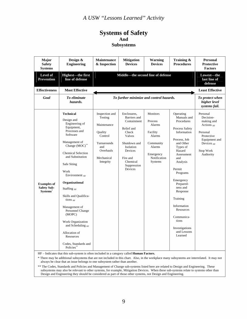
Systems of Safety And
Subsystems
Major Safety
Systems
Design & Engineering
Maintenance & Inspection
Mitigation Devices
Warning Devices
Training & Procedures
Personal Protective
Factors
Level of Prevention
Highest—the first line of defense
Middle—the second line of defense Lowest—the last line of
defense
Effectiveness Most Effective Least Effective
Goal To eliminate hazards.
To further minimize and control hazards. To protect when higher level systems fail.
Examples of Safety Sub-
Systems*
Technical
Design and Engineering of Equipment, Processes and Software
Management of Change (MOC)**
Chemical Selection and Substitution
Safe Siting
Work Environment HF
Organizational
Staffing HF
Skills and Qualifica-tions HF
Management of Personnel Change (MOPC)
Work Organization and Scheduling HF
Allocation of Resources
Codes, Standards and Policies**
Inspection and Testing
Maintenance
Quality Control
Turnarounds and Overhauls
Mechanical Integrity
Enclosures, Barriers and Containment
Relief and Check Valves
Shutdown and Isolation Devices
Fire and Chemical Suppression Devices
Monitors
Process Alarms
Facility Alarms
Community Alarms
Emergency Notification Systems
Operating Manuals and Procedures
Process Safety Information
Process, Job and Other Types of Hazard Assessment and Analysis
Permit Programs
Emergency Prepared-ness and Response
Training
Information Resources
Communica-tions
Investigations and Lessons Learned
Personal Decision-making and Actions HF
Personal Protective Equipment and Devices HF
Stop Work Authority
HF – Indicates that this sub-system is often included in a category called Human Factors. * There may be additional subsystems that are not included in this chart. Also, in the workplace many subsystems are interrelated. It may not
always be clear that an issue belongs to one subsystem rather than another. ** The Codes, Standards and Policies and Management of Change sub-systems listed here are related to Design and Engineering. These
subsystems may also be relevant to other systems, for example, Mitigation Devices. When these sub-systems relate to systems other than Design and Engineering they should be considered as part of those other systems, not Design and Engineering.
9
A USW “Lessons Learned” Activity
10
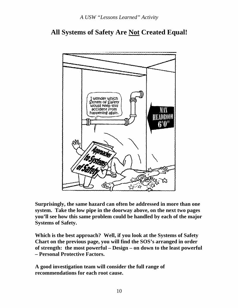
All Systems of Safety Are Not Created Equal!
Surprisingly, the same hazard can often be addressed in more than one system. Take the low pipe in the doorway above, on the next two pages you’ll see how this same problem could be handled by each of the major Systems of Safety. Which is the best approach? Well, if you look at the Systems of Safety Chart on the previous page, you will find the SOS’s arranged in order of strength: the most powerful – Design – on down to the least powerful – Personal Protective Factors. A good investigation team will consider the full range of recommendations for each root cause.
A USW “Lessons Learned” Activity
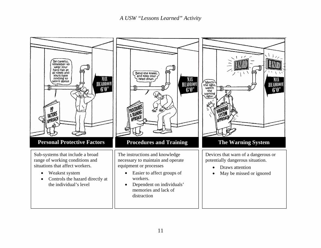
Procedures and Training The Warning System Personal Protective Factors
Sub-systems that include a broad range of working conditions and situations that affect workers.
• Weakest system • Controls the hazard directly at
the individual’s level
The instructions and knowledge necessary to maintain and operate equipment or processes
• Easier to affect groups of workers.
• Dependent on individuals’ memories and lack of distraction
Devices that warn of a dangerous or potentially dangerous situation.
• Draws attention • May be missed or ignored
11
A USW “Lessons Learned” Activity
12
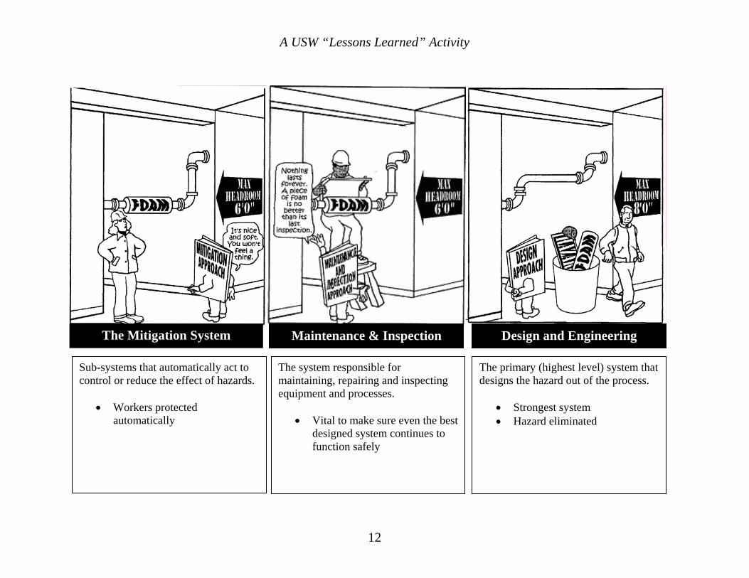
Design and Engineering
The primary (highest level) system that designs the hazard out of the process.
• Strongest system • Hazard eliminated
The system responsible for maintaining, repairing and inspecting equipment and processes.
• Vital to make sure even the best designed system continues to function safely
Maintenance & Inspection Sub-systems that automatically act to
control or reduce the effect of hazards.
• Workers protected automatically
The Mitigation System
A USW “Lessons Learned” Activity
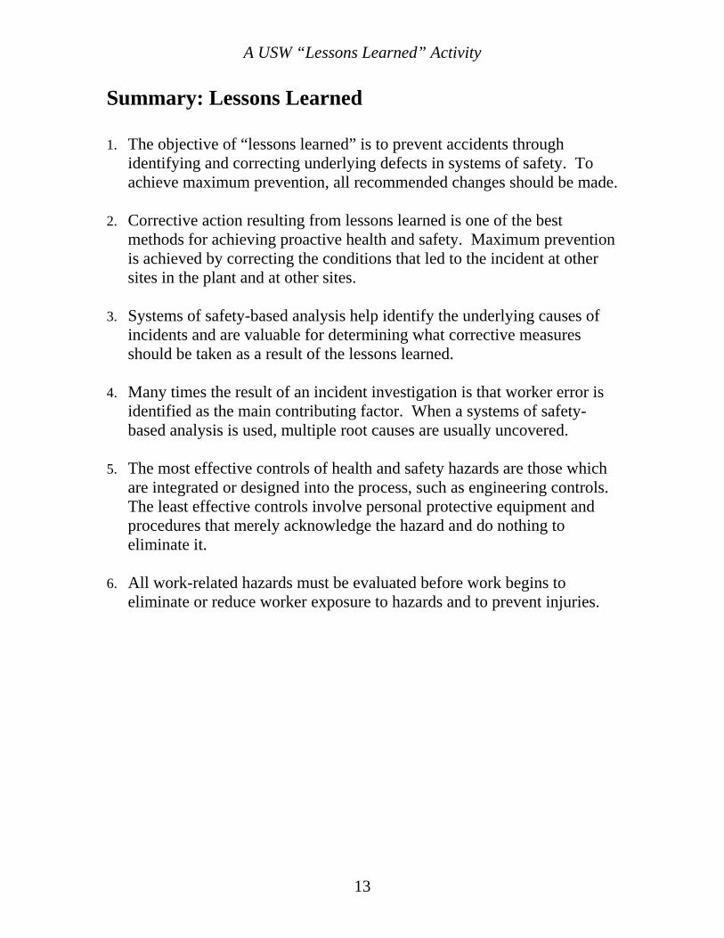
Summary: Lessons Learned 1.
2.
3.
4.
5.
6.
The objective of “lessons learned” is to prevent accidents through identifying and correcting underlying defects in systems of safety. To achieve maximum prevention, all recommended changes should be made.
Corrective action resulting from lessons learned is one of the best methods for achieving proactive health and safety. Maximum prevention is achieved by correcting the conditions that led to the incident at other sites in the plant and at other sites.
Systems of safety-based analysis help identify the underlying causes of incidents and are valuable for determining what corrective measures should be taken as a result of the lessons learned.
Many times the result of an incident investigation is that worker error is identified as the main contributing factor. When a systems of safety-based analysis is used, multiple root causes are usually uncovered.
The most effective controls of health and safety hazards are those which are integrated or designed into the process, such as engineering controls. The least effective controls involve personal protective equipment and procedures that merely acknowledge the hazard and do nothing to eliminate it.
All work-related hazards must be evaluated before work begins to eliminate or reduce worker exposure to hazards and to prevent injuries.
13
A USW “Lessons Learned” Activity
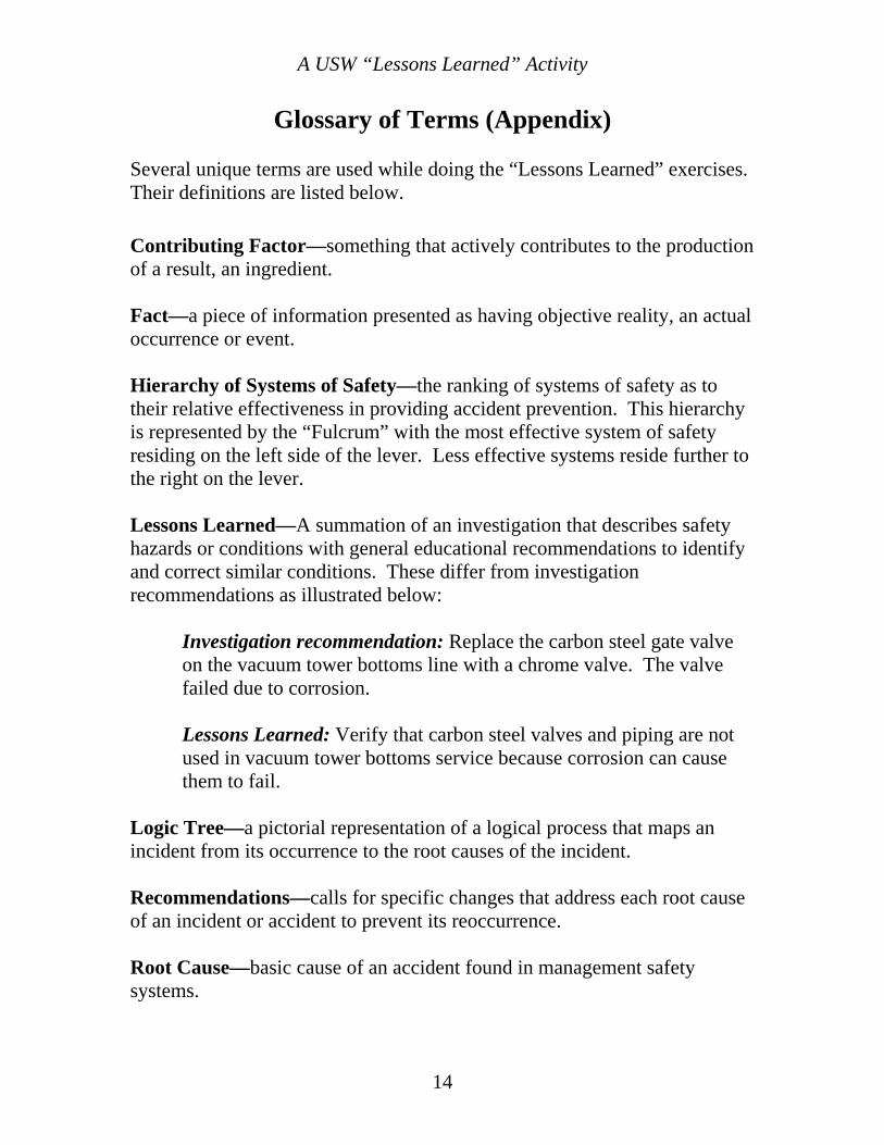
Glossary of Terms (Appendix)
Several unique terms are used while doing the “Lessons Learned” exercises. Their definitions are listed below. Contributing Factor—something that actively contributes to the production of a result, an ingredient. Fact—a piece of information presented as having objective reality, an actual occurrence or event. Hierarchy of Systems of Safety—the ranking of systems of safety as to their relative effectiveness in providing accident prevention. This hierarchy is represented by the “Fulcrum” with the most effective system of safety residing on the left side of the lever. Less effective systems reside further to the right on the lever. Lessons Learned—A summation of an investigation that describes safety hazards or conditions with general educational recommendations to identify and correct similar conditions. These differ from investigation recommendations as illustrated below:
Investigation recommendation: Replace the carbon steel gate valve on the vacuum tower bottoms line with a chrome valve. The valve failed due to corrosion. Lessons Learned: Verify that carbon steel valves and piping are not used in vacuum tower bottoms service because corrosion can cause them to fail.
Logic Tree—a pictorial representation of a logical process that maps an incident from its occurrence to the root causes of the incident. Recommendations—calls for specific changes that address each root cause of an incident or accident to prevent its reoccurrence. Root Cause—basic cause of an accident found in management safety systems.
14
A USW “Lessons Learned” Activity
Glossary of Terms (continued) Supports and Barriers—“supports” are conditions that promote or render assistance to implementing recommendations while “barriers” are conditions that obstruct the implementation of recommendations. Systems of Safety—management systems that actively seek to identify and control hazards before they result in an incident or injury.
Design and Engineering • • • • • •
Maintenance & Inspection Mitigation Devices Warning Systems Procedures and Training Personal Protective Factors
15
A USW “Lessons Learned” Activity
Conducting a “Lessons Learned” Activity
Circle the number that best shows your response to each of the following questions.
1. How easy was it for you to understand the “systems of safety” approach presented in this activity?
4 3 2 1 Very easy Somewhat easy Somewhat hard Very hard
2. How useful do you think this “systems of safety” way of thinking could be for tackling safety and health problems at your workplace?
4 3 2 1 Very useful Somewhat useful Not very useful Of no use
3. How much do you agree or disagree with the following statement: The logic tree diagram approach can be helpful for analyzing the root causes of safety and health incidents.
4 3 2 1
Strongly agree Agree Disagree Strongly disagree
4. Overall, how useful was this “lessons learned activity” for considering safety and health problems at your workplace?
4 3 2 1 Very useful Somewhat useful Not very useful Of no use
16 Volume 4 Issue 2